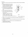
1
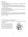
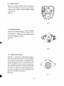
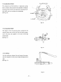
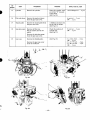
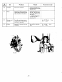
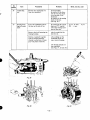
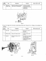
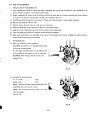
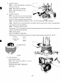
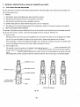
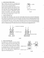
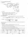
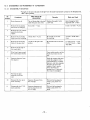
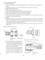
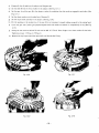
a
Assemble the cylinderhead.
10 mrn flange nut . . . . . . . . . . 4 pcs.
Washer
NOTE:
.................
4 pcs.
Install the intake and exhaust valves. On the
intake side there i s a stem seal.
NOTE: Insert
the push rod. (Exhaust is on the side
of the gear case.) Pay attention to the valve facing, UPwardordownward,and
direction of intake and ex-
haust.
NOTE: Install the rocker arm to the cylinder.
It is advisable to insert the rocker shaft before clamp-
ing the head.
Fig. 47
(See Fig. 47 .)
NOTE: Clamp the head to the cylinder.
Apply "Three Bond #
21I
5" to twopieces of the stud
bolt (on the side of the rocker shaft) and upper and
reverse surfaces of the washer, and then tighten the
nuts.
[Tightening torque: 350 kg-cm]
.
Tightening of the nuts is to be done in three rounds,
I.
e.:
. . . . . . . . . . . . . . . 100 kg-cm
2nd round . . . . . . . . . . . . . . . 200 kg-crn
3rd round . . . . . . . . . . . . . . . 330 350 kgcm
1s t round
-
NOTE: Fasten
6 mm nut
I
tightly the plate (push rod sleeve).
. . . . . . . . . . . . . . . 4 pcs.
(See Fig. 48.)
15)
Adjust the valve clearance.
NOTE: Turn the flywheel by
hand
to the compres-
sion a t TDC (top dead center). At TDC the camshaft
DECOMPRESSiON \,
ADJUSTING SCREW
cranking pin stands vertically.
NOTE: Adjustthe valve clearance to anywherebetween 0.07
-
0.10 mm (both intake and exhaust),
when the engine is cold.
(See Fig. 49.)
Fig. 49
- 25 -