1
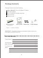
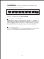
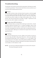
TM
Mico-Switch/8
8 Port 10/100Base-TX Switch
(Auto MDI/MDIX)
FEP-32008T-3
USER’S MANUAL
Package Contents
Package contents include the following:
Micro-Switch/8; 8 Port 10/100Base-TX Switch
DC power adapter
Four (4) adhesive-backed rubber feet
User’s manual
Warranty card
TM
TM
Mico-S witch/8
8 Port 10/100Base
-TX Switch
(Auto MDI/MDIX)
FEP-32008T-3
USER’S MANUAL
Micro-Switch/8
8 port Switch
User’s Guide
Rubber feet
Power Adapter
Figure 1. Contents of package
IMPORTANT: If any piece is missing or damaged, please contact your
local dealer or reseller for service.
For Your Records
Product Name:
Serial Number:
Date of Purchase:
Purchased from:
Notes:
1
Introduction
The 8 port Mico-Switch/8 (Auto MDI/MDIX) is a compact Fast Ethernet
switch that provides wire-speed, a Fast Ethernet switching function which
allows high-performance, low-cost connections to Full-duplex, Half-duplex
10Mbps and 100Mbps Ethernet networks. The Mico-Switch/8 delivers
all the advantages of a switching hub in a compact desktop size and is
ideal for small office or SOHO network users. It’s also wall mountable
which conserves office space.
This Switch provides eight auto-sensing 10/100Mbps Ethernet RJ-45
ports which automatically detect the speed of the devices that you plug
into them. This switching function allows 10Mbps, 100Mbps, Full-duplex
and Half-duplex devices to communicate on the same network without
having to replace any infrastructure. This flexible feature allows your
network a timely, economical migration to 100Mbps Fast Ethernet.
Key Features
Conforms to IEEE802.3, 802.3u, 802.3x
Automatic MDI/MDIX crossover for all ports
N-Way Auto-negotiation for 10/100Mbps transmissions
Space-saving compact size
Store-and-Forward switching architecture
Auto-detection of full/half-duplex mode in all ports
Plug-and-Play configuration auto address learning
768Kbit packet buffer
LED indicators for Power, Link/activity, and Full Duplex/Collision
For full coverage of your warranty, be sure
to register your product using the enclosed
registration card.
2
Hardware Description
The Front Panel
The front panel consists of LED Indications.
LED Indicators
Per Device:
Per Port:
Power
LINK/ACT (Link/Activity)
Power Indicator
Power
Mico-Switch/8
LINK/ACT
8 Port 10/100Base-TX Switch
1
2
3
4
5
6
7
8
LINK/ACT Indicators
Figure 2. Front panel view of LED indications
LED
Status
Color
Description
Power
On
Green
The switch is supplied with suitable
power.
On
Green
The port is connecting at 10Mbps.
Blinks
-
The port is receiving or transmitting
data.
Off
-
The port is not linked successfully
with the device.
LINK/ACT
3
The Real Panel
The rear panel view of the Mico-Switch/8 consists of a DC power
connector and 8 auto-sensing ports.
8
7
6
5
4
3
2
1
DC 9V
Figure 3. Rear panel view of the Micro-Switch/8
RJ-45 Ports ( Auto MDI/MDIX )
8 auto-sensing ports of 10/100 N-way for 10Base-T or 100Base-TX
connections. [ In general, MDI means connecting to another Hub or
Switch while MDIX means connecting to a workstation or PC. Therefore,
Auto MDI/MDIX means that you can connect to another Switch or
workstation without changing pin-to-pin or crossover cabling. ]
DC Power Connector
Plug the female connector into the switch and male connector into
a power outlet. Supports input voltages 9 VDC at 700 mA.
4
Troubleshooting
The Switch can be easily monitored through panel indicators to assist
in identifying problems. This section describes common problems you
may encounter and possible solutions.
Power
If the power indicator does not light when the power cord is plugged
in, you may have a problem with the power outlet or cord. However, if
the power LED goes off after running for a while, check for loose power
connections, power losses or surges at the power outlet. Turn off
power, wait 30 seconds and turn power on again. If problem is still
not resolved call for dealer ’s assistance
Diagnosing LED Indicators
If link indicator does not light after making a connection, check
whether network interface (e.g., a network adapter card on the
attached device), network cable, or switch port is defective. Be sure
the cable is plugged into both the switch and corresponding device.
Verify the proper cable type is used and its length does not exceed
specified limits.
Cabling
Verify that the cabling type is correct. Make sure all cable connectors
are securely seated in the required ports. Use only standard
Unshielded Twisted-Pair (UTP), Category 3, 4, 5, or 5e cables. Use
only Category 5 or 5e when connecting with Fast Ethernet. Make
certain the maximum distance between the Switch and what it’s
connected to is 100 meters or less.
NOTE: Do not plug a standard telephone cord into an RJ-45 port.
This may damage the switch
5
Product Specifications
Standard
Compliance:
IEEE 802.3 10Base-T Ethernet
IEEE 802.3u 100Base-TX Fast Ethernet
IEEE 802.3x Flow Control
Portocol:
CSMA/CD
Transfer Rate:
14,880 pps for 10Mbps
148,800 pps for 100Mbps
Connector:
RJ 45
MAC Address:
Memory Buffer:
1K Mac address table
LED Indicator:
Per port: Link/Activity
Auto MDIX on all ports
768KBits
Per unit: Power
Network Cable:
10Base-T: 2-pair UTP Cat. 3,4,5e cable
(100m), EIA/TIA-568 100-ohm STP (100m)
100Base-T: 2-pair UTP Cat. 5e cable (100m),
EIA/TIA-568 100-ohm STP (100M)
Dimension:
137mm x 74mm x 24mm (W x D x H)
Operating Temp:
0℃ to 45℃ (32℉ to 113℉)
Operating Humidity: 10% to 90% (Non-condensing)
External power supply
Power Supply:
DC 9V, 700mA
Power Consumption: 5.8 Watt @ AC 240V/60Hz (Maximum)
EMI:
FCC Class B
CE
FCC Statement
This equipment has been tested and found to comply with the limits for a class B
device, pursuant to part 15 of the FCC rules. These limits are designed to provide
reasonable protection against harmful interference in a commercial installation.
This equipment generates, uses and can radiate radio frequency energy and, if not
installed and used in accordance with instructions, may cause harmful
interference with radio communications. Operation of this equipment in a
residential area is likely to cause harmful interference, in which case, the user will
be required to correct the interference at the user’s expense.
6
TM
565 Brea Canyon Rd., Ste A
Walnut, CA 91789
Phone: 626.964.7873
www.unicomlink.com
Fax: 626.964.7880
e-mail: [email protected]
@UNICOM 2007. UNICOM and “A Network Systems Solution” are trademarks of UNICOM Electric, Inc.
All rights reserved. Specifications subject to change without notice.
Rev: 11.12