1
Installation and service
instructions
VIESMANN
for contractors
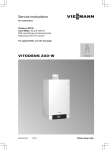
Vitocal 242-G
Compact heat pump with electric drive, 400 V~ and 230 V~
For applicability, see the last page
VITOCAL 242-G
5441 603 GB
8/2009
Please keep safe.
Safety instructions
Safety instructions
Please follow these safety instructions closely to prevent accidents and material losses.
Danger
This symbol warns against the
risk of injury.
!
Please note
This symbol warns against the
risk of material losses and environmental pollution.
Note
Details identified by the word "Note" contain additional information.
Working on the system
■ Isolate the system from the power supply and check that it is no longer 'live',
e.g. by removing a separate fuse or by
means of a main isolator.
■ Safeguard the system against unauthorised reconnection.
!
Target group
These instructions are exclusively
designed for qualified personnel.
■ Work on electrical equipment must
only be carried out by a qualified electrician.
■ The system must be commissioned by
the system installer or a qualified person authorised by the installer.
Regulations
Observe the following when working on
this system
■ all legal instructions regarding the prevention of accidents,
■ all legal instructions regarding environmental protection,
■ the Code of Practice of relevant trade
associations.
■ all current safety regulations as
defined by DIN, EN, DVGW, VDE and
all locally applicable standards
2
Please note
Electronic modules can be damaged by electrostatic discharges.
Touch earthed objects, such as
heating or water pipes, to discharge static loads.
Repair work
!
Please note
Repairing components that fulfil a
safety function can compromise
the safe operation of your heating
system.
Replace faulty components only
with original Viessmann spare
parts.
5441 603 GB
Safety instructions explained
Safety instructions
Safety instructions (cont.)
Ancillary components, spare and
wearing parts
Please note
Spare and wearing parts that
have not been tested together
with the heating system can compromise its function. Installing
non-authorised components and
non-approved modifications or
conversions can compromise
safety and may invalidate our
warranty.
For replacements, use only original spare parts supplied or
approved by Viessmann.
5441 603 GB
!
3
Index
Index
Installation instructions
Preparing for installation
Installation............................................................................................................
System example...................................................................................................
8
8
Installation sequence
Opening and separating the heat pump...............................................................
Installing the heat pump.......................................................................................
Hydraulic connections..........................................................................................
Electrical connections...........................................................................................
Power supply........................................................................................................
Connecting to terminals X3.8/X3.9.......................................................................
Closing the heat pump.........................................................................................
12
21
23
26
28
37
37
Service instructions
Commissioning, inspection, maintenance
Steps - commissioning, inspection and maintenance.......................................... 38
Further details regarding the individual steps....................................................... 39
Troubleshooting
Messages.............................................................................................................
Diagnosis (service scans)....................................................................................
Testing outputs (actuator test)..............................................................................
Function check.....................................................................................................
Steps if the room temperature is too low..............................................................
No display indication on the programming unit....................................................
Repairs.................................................................................................................
47
63
68
68
69
70
71
Parameter group system definition
Parameter group system definition.......................................................................
7000 System scheme...........................................................................................
7001 Language....................................................................................................
7003 Temperature differential for the heating limit...............................................
7004 Temperature differential for the cooling limit...............................................
7010 External extension.......................................................................................
7008 Swimming pool............................................................................................
7011 External operating mode changeover.........................................................
7012 Operating mode for external operating mode changeover..........................
7013 Duration of external operating mode changeover.......................................
7014 External demand mixer "OPEN"..................................................................
4
78
78
78
79
79
80
80
81
82
83
85
5441 603 GB
Control unit settings by the contractor............................................................ 76
Index
Index
7015 External blocking mixer "CLOSED"............................................................. 85
7017 Vitocom 100................................................................................................ 86
701B Common system temperature sensor......................................................... 86
5441 603 GB
Parameter group compressor
Parameter group compressor............................................................................... 88
5000 Enable compressor..................................................................................... 88
5030 Heat pump output........................................................................................ 88
Parameter group DHW
Parameter group DHW.........................................................................................
6000 Set cylinder temperature.............................................................................
6015 DHW reheating............................................................................................
6005 Minimum temperature for DHW cylinder.....................................................
6006 Maximum temperature for DHW cylinder....................................................
6007/6008 DHW / Booster heater hysteresis.......................................................
6009 DHW start optimisation................................................................................
600A DHW stop optimisation...............................................................................
600C Set DHW temperature 2.............................................................................
600E Temperature sensor 2.................................................................................
6016 DHW heating priority...................................................................................
6017 DHW at control high pressure.....................................................................
6020 Cylinder primary pump operating mode......................................................
89
89
89
90
90
91
92
92
92
92
93
93
93
Parameter group solar
Parameter group solar..........................................................................................
7A00 Solar control unit.........................................................................................
7A01 Maximum collector temperature..................................................................
7A02/7A03 Solar circuit pump hysteresis.............................................................
7A07 Solar circuit flow rate...................................................................................
7A09 Fault message faulty circulation..................................................................
94
94
94
94
95
95
Parameter group electric heater
Parameter group electric heater...........................................................................
7900 Instantaneous heating water heater (accessory)........................................
7902 Heating mode with booster heater..............................................................
7907 Max. stage instantaneous heating water heater.........................................
790A Stage at power-OFF...................................................................................
790B Dual mode temperature instantaneous heating water heater.....................
96
96
97
97
97
98
Parameter group internal hydraulics
Parameter group internal hydraulics.................................................................... 99
7300 Heat pump for drying a building.................................................................. 99
5
Index
Index
7303 Screed program .......................................................................................... 99
730D Operation with three-way diverter valve..................................................... 101
730C Set flow temperature, external demand...................................................... 102
7320 Primary pump operating mode.................................................................... 102
7340 Secondary pump operating mode............................................................... 102
Parameter group buffer cylinder
Parameter group heating water buffer cylinder.................................................... 104
7200 Heating water buffer cylinder....................................................................... 104
7202 Set temperature for "fixed value"................................................................. 104
7203 Hysteresis.................................................................................................... 104
7204 Maximum temperature................................................................................ 105
7208 Dual mode temperature heating water buffer cylinder................................ 106
Parameter group heating circuits/cooling circuit
Parameter group heating circuits......................................................................... 107
2000/2001/2022 Room temperatures and switching times.................................. 107
2003 Enabling the remote control........................................................................ 107
2006/2007 Heating curve slope/level................................................................... 108
200A Influence of room temperature hook-up...................................................... 108
200B Room temperature hook-up (heating circuits)............................................. 108
200E Maximum set flow temperature................................................................... 109
Parameter group cooling
Parameter group cooling...................................................................................... 110
7100 Cooling mode.............................................................................................. 110
7101 Cooling circuit.............................................................................................. 110
7102 Room temperature separate cooling circuit................................................. 111
7103 Minimum flow temperature for separate cooling circuit............................... 111
7104 Room hook-up cooling circuit...................................................................... 111
7110/7111 Cooling curve (cooling circuit/separate cooling circuit)...................... 112
Parameter group communication
Parameter group communication......................................................................... 114
7710 LON communication module....................................................................... 114
7798/7777 LON system number/subscriber number............................................ 114
7779 Fault manager............................................................................................. 115
779C Receive interval for data............................................................................. 115
7797 Outside temperature via LON...................................................................... 116
6
5441 603 GB
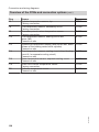
Parameter group time
Parameter group time........................................................................................... 113
7C00 - 7C06 Summertime/wintertime.................................................................. 113
Index
Index (cont.)
77FF Time via LON.............................................................................................. 116
Parameter group operation
Parameter group operation.................................................................................. 118
8800 Lock out controls......................................................................................... 118
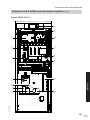
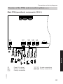
Connection and wiring diagrams
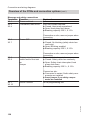
Overview of the PCBs and connection options.................................................... 119
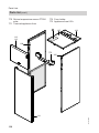
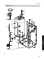
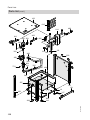
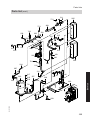
Parts lists
Parts list................................................................................................................ 129
Commissioning/service reports
Hydraulic parameters report................................................................................. 137
Control parameter report...................................................................................... 137
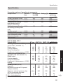
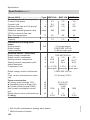
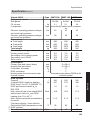
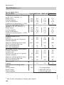
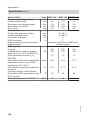
Specification....................................................................................................... 141
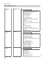
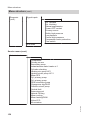
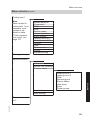
Menu structure................................................................................................... 147
Declaration of Conformity
Declaration of conformity...................................................................................... 152
5441 603 GB
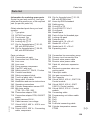
Keyword index.................................................................................................... 153
7
Preparing for installation
Installation
!
!
Please note
The installation room must be dry
and free from the risk of frost.
Ensure ambient temperatures of
0 to 35 ºC.
Minimum room volume
Maintain the minimum room volume
required by DIN EN 378; see Viessmann
"Technical guides for heat pumps".
Minimum clearances
Please note
Observe the permissible floor
load.
■ Total weight of filled DHW cylinder:
BWT 106
BWT 108
BWT 110
491 kg
491 kg
498 kg
■ To prevent structure-borne
noise, never set up the appliance on ceilings with wooden
joists (e.g. in the attic).
■ Level the appliance.
If the adjustable feet are used
to compensate for an uneven
floor (max. 10 mm), the pressure load on the feet must be
distributed evenly.
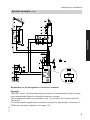
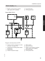
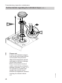
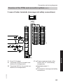
System example
Note
This scheme is a basic example without
shut-off valves or safety equipment. This
does not replace the local technical engineering task.
5441 603 GB
Select system scheme 2 (see
page 78)
■ 1 underfloor heating circuit without
mixer (A1)
■ DHW heating with integral DHW cylinder
■ Option:
DHW heating with a solar thermal system
8
Preparing for installation
System example (cont.)
2/F21
A1
2/145
2/F14
2/211.1
P
2/X4.1/2
M
Installation
2/212.4
M
2/211.5
2/212.3
WW
2/F0
2/X3.8
2/X3.9
F0
F14
F21
145
P
2/211.3
X3.8/9
X4.1/2
211.2
211.3
211.5
212.3
212.4
P
2/212.4
P
Explanation of the designation of electrical contacts
5441 603 GB
Example:
"2/211.2" at pos. oR Secondary pump connection via temperature limiter as maximum temperature limiter for underfloor heating (in series):
The temperature limiter is connected to pos. 2 (control unit) / terminal strip 211 .
Terminal 2
For further details regarding the electrical connections, see chapter "Overview of
PCBs and connection options" from page 119.
9
Preparing for installation
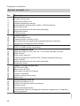
System example (cont.)
Pos.
1
2
3
4
6
qW
qE
qT
wP
wQ
wW
wU
eU
rQ
rW
rE
rR
rT
rI
rO
iP
iQ
iW
iE
iR
iT
5441 603 GB
oP
oQ
oW
oE
oR
Description
Heat source
Compact heat pump
Heat pump control unit
Outside temperature sensor
Instantaneous heating water heater, 9 kW (accessory)
Secondary pump
Safety equipment block with safety assembly
Expansion vessel
Primary pump
Primary circuit
Brine accessory pack
Pressure switch, primary circuit
Brine distributor for geothermal probes/geothermal collectors
Geothermal probe/geothermal collector
DHW heating
DHW circulation pump (accessory)
DHW heating with solar
High limit safety cut-out (max. 95 °C) for DHW cylinders (on site)
Solar-Divicon
Solar circuit pump R1
Collector temperature sensor KOL (Vitosolic standard delivery)
Solar collector
Safety equipment block with safety assembly
Expansion vessel
Natural cooling function (NC)
NC-Box with mixer
Mixer motor NC-Box
Secondary cooling circuit pump
Contact humidistat
Primary cooling circuit pump
Mixer motor
Direct heating circuit A1
Underfloor heating circuit
Vitotrol 200 remote control (accessory)
Overflow valve
Flow temperature sensor
Temperature limiter for limiting the maximum temperature of underfloor
heating systems
10
Preparing for installation
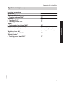
System example (cont.)
"2"
"1"
"1"
"4"
Set switching times (see
operating instructions)
"1"
"1"
5441 603 GB
"Heating circuit A1"
■ "Remote control 2003"
"Electric heater"
■ "Inst.htg.water heat 7900"
Setting
Installation
Required parameters
Parameter
"System definition"
■ "System scheme 7000"
"Cooling"
■ "Cooling 7100"
■ "Cooling circuit 7101"
"Solar"
■ "Solar control unit type 7A00"
For accessories (if installed):
DHW circulation pump
11
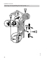
Installation sequence
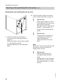
Opening and separating the heat pump
During handling, the cylinder module can
be removed (see page 13 onwards). In
addition, the heat pump module can be
removed (see page 18).
Please note
Avoid damaging the appliance
during handling.
Never put weight on the top, front
or side panels of the appliance.
Please note
Installing a compressor at a steep
angle inside the heat pump can
result in equipment damage.
Never tilt the heat pump more
than 45° during handling and
installation.
5441 603 GB
!
!
12
Installation sequence
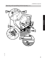
Opening and separating the heat pump (cont.)
Removing the cylinder module
5.
Installation
4.
1.
2.
2x
5441 603 GB
3.
13
Installation sequence
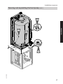
Opening and separating the heat pump (cont.)
8.
9.
11.
sXF
400 V
2x
230 V
2x
10.
4x
6.
X3
5441 603 GB
7.
sG
sH
lJ
aYH
14
Installation sequence
Opening and separating the heat pump (cont.)
16.
17.
2x
14.
Installation
2x
18.
12.
13.
5441 603 GB
15.
15
Installation sequence
Opening and separating the heat pump (cont.)
6x
22.
4x
21.
2x
19.
4x
5441 603 GB
20.
16
Installation sequence
Opening and separating the heat pump (cont.)
Installation
23.
26.
25.
2x
4x
5441 603 GB
24.
17
Installation sequence
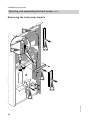
Opening and separating the heat pump (cont.)
Removing the heat pump module
6.
sH
aYH
1.
3.
4.
kK
2.
1.
5441 603 GB
5.
18
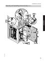
Installation sequence
Opening and separating the heat pump (cont.)
aJ
9. 4x
10.
4x
?
Installation
11.
sH
kK
aYH
8.
2x
7.
5441 603 GB
12.
19
Installation sequence
Opening and separating the heat pump (cont.)
Assembly and sealing faces to note
2. Fit the cylinder module in reverse
order to that described on page 13.
!
A
1. Install the heat pump module in
reverse order to that described on
page 18.
With pipe outlets, ensure pipe glands
A are seated correctly.
Seal pipe glands A with adhesive
tape.
!
Please note
Make tight hydraulic connections between the heat pump
and cylinder modules.
With pipe outlets, ensure pipe
glands C are seated correctly (see the following diagram).
Please note
To prevent the formation of
condensate and extreme
noise development,
tightly seal the control unit
door.
Note
Because of the sound insulating mat,
the control unit door stands out
slightly when closed.
Please note
Seal the appliance to be
soundproof and diffusionproof.
Sealing tape on the side panels must be in close contact
with sealing faces B on the
casing.
5441 603 GB
!
20
Installation sequence
Opening and separating the heat pump (cont.)
Installation
C
BB
5441 603 GB
Installing the heat pump
Install the heat pump according to the
details on page 8.
21
Installation sequence
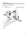
Installing the heat pump (cont.)
Removing the transport brackets
!
Please note
If transport brackets are not
4.
removed, they cause vibrations
and excessive development of
noise.
2x
2.
3.
2x
5441 603 GB
1.
22
Installation sequence
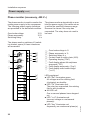
Hydraulic connections
A BCD
E
M
L
A
B
C
D
E
F
G
H
K
L
M
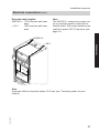
Entry for low voltage cables < 42 V
DHW
DHW circulation
Entry for 230 V cables
Cold water
Primary circuit return (heat pump
brine outlet)
Primary circuit flow (heat pump
brine inlet)
Heating water flow
Heating water return
Solar circuit return
Solar circuit flow
F
G
H
5441 603 GB
K
23
Installation
Overview of connections
Installation sequence
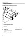
Hydraulic connections (cont.)
Connecting the primary/secondary circuit
2.
4x
A
B
1.
4x
A Straight pipe sections supplied
B Pipe bends from connection set primary/secondary circuit (accessories, see separate installation
instructions)
!
24
Please note
The components used must be
resistant to the heat transfer
medium.
Never use zinc-plated/galvanised pipes.
1. Equip the primary circuit with an
expansion vessel and safety valve (in
accordance with DIN 4757).
5441 603 GB
Connecting the primary circuit
Installation sequence
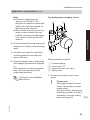
Hydraulic connections (cont.)
Connecting the secondary circuit
E
F
Installation
Note
■ Expansion vessel must be
approved to DIN 4807. Diaphragms of expansion vessel and
safety valve must be suitable for
the heat transfer medium.
■ Blow-off and drain lines must converge in one container that can
hold the maximum possible expansion volume of the heat transfer
medium.
2. Ensure adequate thermal and sound
insulation of all pipes routed through
walls.
3. Insulate lines inside the building to
provide protection from heat and
vapour diffusion.
D
C
Safety assembly supplied
4. Connect primary lines to heat pump:
With straight pipe sections supplied
or
With connection set primary/secondary circuit (accessory set with
angled pipe sections)
Pressure gauge
Connection G 1"
Quick-action air vent valve
Safety valve
1. Connect secondary lines to heat
pump:
!
Please note
Make tight hydraulic connections on the primary and secondary sides.
With pipe outlets, ensure pipe
glands are seated correctly (if
necessary, seal with sealing
tape; see page 20).
5441 603 GB
Connection set installation
instructions
C
D
E
F
25
Installation sequence
Hydraulic connections (cont.)
2. Install the safety assembly provided:
Either to the on-site line in the heating
water return
or
To the connection set primary circuit/
secondary circuit (accessories)
Connection set installation
instructions
Note
■ In underfloor heating circuits, integrate
a temperature limiter on site for limiting
the maximum temperature of underfloor heating systems.
■ Safeguard minimum flow rate, e.g.
with overflow valve (see Specification
on page 141).
■ Equip the secondary circuit on site with
an expansion vessel.
3. Fill and vent secondary circuit.
4. Thermally insulate pipes inside the
building.
Connecting the solar circuit
Connect the solar circuit on site.
Electrical connections
For further information, an overview of
the electrical connections and more
details regarding the PCBs, see
page 119 onwards.
5441 603 GB
Danger
Damaged cable insulation can
cause injury and damage to the
appliance.
Route cables so that they cannot
touch very hot, vibrating or sharpedged components.
Danger
Incorrectly routed wiring can lead
to serious injury from electrical
current and result in equipment
damage.
■ Route 230 V cables and LV
cables separately.
■ Strip the insulation from the
cables as close to the terminals
as possible, and bundle tightly
to the associated terminals.
■ Secure cables with cable ties.
This ensures that, in case of failure, for example when detaching
a wire, the wires cannot drift into
the adjacent voltage area.
26
Installation sequence
Electrical connections (cont.)
Required cable lengths:
400/230 V~ 1700 mm plus wall clearance
< 42 V
1500 mm plus wall clearance
Note
The 400/230 V~ compressor power supply is protected against contact with a
contact shield. This contact shield can be
sealed for power-OFF (if required) (see
page 31).
400/230 V
Installation
< 42 V
<4
2V
40
0/2
3
0V
5441 603 GB
Note
High wall outlet for electrical cables: 2100 mm (see "Technical guides for heat
pumps")
27
Installation sequence
Power supply
Danger
Incorrectly executed electrical
installations can lead to injury
from electrical current and result
in equipment damage.
Make the power supply connection and implement all earthing
measures (e.g. RCD circuit) in
accordance with the following
regulations:
■ IEC 60364-4-41
■ VDE requirements
■ Requirements specified by
your local power supply utility
■ Protect the power cable to the
control unit with no more than
16 A.
Isolator for non-earthed conductors
■ The main isolator (if installed) must
simultaneously isolate all non-earthed
conductors from the mains with a minimum contact separation of 3 mm.
■ If no main isolator is installed, all nonearthed cables must be isolated from
the mains by the upstream breaker
with at least 3 mm contact separation.
Danger
Incorrect core termination can
cause severe injuries and damage to the equipment.
Never interchange cores "L" and
"N".
5441 603 GB
Danger
The absence of component
earthing in the system can lead to
serious injury from electrical current if an electrical fault occurs.
The equipment and the pipework
must be connected to the earth
bonding of the house in question.
28
Installation sequence
Power supply (cont.)
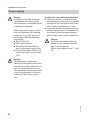
Information regarding the compressor power supply
■
Please note
An incorrect phase sequence
can cause damage to the unit.
Make the compressor power
supply only in the phase
sequence specified (see terminal) with a clockwise rotating
field.
!
5441 603 GB
■ If full wave soft starter is installed (see
type plate), the compressor power
fuses must have Z characteristics.
■ If compressor and/or instantaneous
heating water heater (accessory) are
operated at a lower tariff (power-OFF),
provide an additional cable (e.g.
NYM 3 x 1.5 mm2) for the power-OFF
signal from the distribution board
(meter box) to the control unit.
Information regarding the control unit
power supply
■ Protect the power supply to the control
unit with no more than 16 A.
■ For accessories and external components which are not to be connected to
the control unit, we recommend making the power connection to the same
fuse, but with at least the same phase
as the control unit.
Connection to the same fuse/MCB
provides additional safety when the
power is switched off. Observe the
power consumption of the consumers
connected (see page 141).
■ The power supply to the control unit
(3 x 1.5 mm2) and the cable for the
power-OFF signal can be combined in
a five-core cable. Observe the technical connection requirements of the
power supply utility.
Information regarding the power supply utility
■ In negotiations with your power supply
utility, different supply tariffs for the
main power circuits may be offered.
■ The control unit/electronics feed
must be implemented without possible blocking from the power supply utility; tariffs that are subject to possible
shutdowns must not be applied to
these feeds.
■ The allocation of the power-OFF (for
compressor and/or instantaneous
heating water heater) is made via the
type of connection and by a setting in
the control unit (see pages 31 and
97). In Germany, the power supply
can be cut off for up to 3 x 2 hours
within any 24 h period.
29
Installation
General information regarding the power supply
Installation sequence
Power supply (cont.)
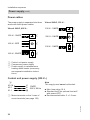
Power cables
The power supply is separated into three
areas with three power cables:
Vitocal 242-G, 230 V~
Vitocal 242-G, 400 V~
230 V~ 1/N/PE
A
230 V~ 1/N/PE
B
230 V~ 1/N/PE
C
230 V~ 1/N/PE
A
400 V~ 3/PE
B
400 V~ 3/N/PE
C
A Control unit power supply
B Compressor power supply
C Power supply to instantaneous
heating water heater (accessory;
see separate installation instructions)
Control unit power supply (230 V~)
A
X3.18
X2.1
X1.1
L1
1/N/PE
N
230 V/ 50 Hz
?
■ Max. fuse rating 16 A
■ Standard tariff (no optional low tariff
with power-OFF)
■ Recommended cable: 3 x 1.5 mm2
5441 603 GB
A Mains terminals on the 3 rows of
screw terminals (see page 125)
Note
This supply must never be blocked.
30
Installation sequence
Power supply (cont.)
Vitocal 242-G, 400 V~
3/PE
400 V, 50 Hz
L1
L2
L3
L1
L2
L3
N
?
?
A
A Compressor mains terminals
behind contact shield (see
page 119).
Vitocal 242-G, 230 V~
L1
1/N/PE
230V/ 50 Hz N
L1
L1
N
N
?
?
?
■ Fuse protection in accordance with the
compressor rating (see specification
on page 141/type plate).
For appliances with full wave soft
starter, the upstream fuses must have
Z characteristics.
■ Low tariff and power-OFF can be
used.
■ No parameters need to be set when
using low tariff with power-OFF. During the power-OFF period, the compressor is shut down.
■ Recommended cable for the Vitocal
242-G, 400 V~: 5 x 2.5 mm2
Recommended cable for the Vitocal
242-G, 230 V~: 3 x 4 mm2 for cable
lengths up to 20 m; for cable lengths
> 20 m, a larger cable cross-section is
required.
A
Power supply with power-OFF
Power-OFF without on-site load disconnection
5441 603 GB
The power-OFF signal is connected
directly in the control unit. The compressor is "forced" off when power-OFF is
enabled.
Parameter "Stage at power-OFF" is
used to determine whether and at what
stage the instantaneous heating water
heater (accessory) remains operational
(see page 97).
Note
Observe the technical connection conditions of the relevant power supply utility.
31
Installation
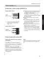
Compressor power supply (400/230 V~)
Installation sequence
Power supply (cont.)
Vitocal 242-G, 400 V~
X3.7
A
X3.6
B
3
5
≈
3
kWh
E
3/N
4
4
3
kWh
D
C
3/N
F
H
4
G
4
Diagram excluding fuses and RCD.
E Ripple control receiver (contact
open: power-OFF enabled)
F Backup fuse ripple control receiver
G TNC system feed
H Low tariff meter
5441 603 GB
A Control unit (for connection to luster
terminals, see page 125)
B Instantaneous heating water heater
(accessory)
C Compressor
D High tariff meter
32
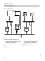
Installation sequence
Power supply (cont.)
Vitocal 242-G, 230 V~
X3.7
A
X3.6
B
7
3
Installation
3
C
≈
kWh
D
1/N
kWh
E
1/N
H
F
G
Diagram excluding fuses and RCD.
E Ripple control receiver (contact
open: power-OFF enabled)
F Backup fuse ripple control receiver
G TNC system feed
H Low tariff meter
5441 603 GB
A Control unit (for connection to luster
terminals, see page 125)
B Instantaneous heating water heater
(accessory)
C Compressor
D High tariff meter
33
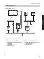
Installation sequence
Power supply (cont.)
Power-OFF with on-site load disconnection
The power-OFF signal is connected to
the on-site contactor of the low tariff
power supply and in the control unit. The
compressor and instantaneous heating
water heater (accessory) are "forced" off
when power-OFF is enabled.
Note
Observe the technical connection conditions of the relevant power supply utility.
Vitocal 242-G, 400 V~
X3.7
X3.6
A
C
B
D
3
4
5
E
≈
3
3
kWh
kWh
3/N
F
3/N
G
4
H
4
4
K
A Control unit (for connection to luster
terminals, see page 125)
B Instantaneous heating water heater
(accessory)
34
C
D
E
F
Compressor
Control unit power supply
Main isolator
High tariff meter
5441 603 GB
Diagram excluding fuses and RCD.
Installation sequence
Power supply (cont.)
G Ripple control receiver (contact
open: power-OFF enabled)
H Low tariff meter
K TNC system feed
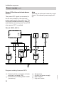
Vitocal 242-G, 230 V~
X3.7
X3.6
C
B
D
3
Installation
A
3
7
E
≈
kWh
kWh
1/N
F
1/N
G
H
K
Diagram excluding fuses and RCD.
E Main isolator
F High tariff meter
G Ripple control receiver (contact
open: power-OFF enabled)
H Low tariff meter
K TNC system feed
5441 603 GB
A Control unit (for connection to luster
terminals, see page 125)
B Instantaneous heating water heater
(accessory)
C Compressor
D Control unit power supply
35
Installation sequence
Power supply (cont.)
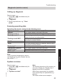
Phase monitor (accessory, 400 V~)
The phase monitor is used to monitor the
mains power supply to the compressor.
The following power supply deviations
are permitted in the delivered condition:
Over/undervoltage
Phase asymmetry
Switching delay
15 %
15 %
4s
The phase monitor automatically re-enables the power supply if the values return
to within the specified tolerance range.
Remove the cause if the relay has
responded. The relay does not need to
be reset.
The phase monitor switches off (switching contact opens) if these tolerances
are exceeded.
A
B
20
<>U
Ph
Asy
15
%
5
6
C
t
Asy
%
2
10
<>U
4
Rel
H
G
F
E
12
0.1
12
11
D
14
D
L3
L2
L1
A2
A1
36
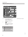
A
B
C
D
E
F
Over/undervoltage in %
Phase asymmetry in %
Switching delay in s
Contact used in safety chain (N/O)
Operating display ("Rel")
Fault display phase failure/phase
sequence ("Ph")
G Fault display asymmetry ("Asy")
H Fault display over/undervoltage
("<>U")
LEDs explained
■ LED "Rel" illuminates green:
All voltages and the rotating field
(clockwise) are healthy.
■ LED "Ph" illuminates red:
The relay has responded; the rotating
field is anti-clockwise.
■ All LED's off:
One or several phases have dropped
out.
■ LED "<>U" illuminates red:
Incorrect voltage on one/several
phase(s).
■ LED "Asy" illuminates red:
Asymmetry on one/several phase(s).
5441 603 GB
10
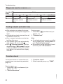
Installation sequence
Connecting to terminals X3.8/X3.9
After connecting the power supply, a
connection must be made at terminals
X3.8 and X3.9:
■ Primary circuit pressure switch and/or
frost stat
or
■ Jumper from the pack
Installation
Closing the heat pump
5441 603 GB
See page 20.
37
Commissioning, inspection, maintenance
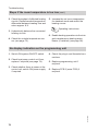
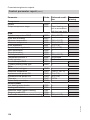
Steps - commissioning, inspection and maintenance
For further information regarding the individual steps, see the page indicated
Commissioning steps
Inspection steps
Maintenance steps
•
•
•
•
•
•
1. Writing reports................................................................ 39
•
•
2. Checking the refrigeration circuit for leaks................. 39
3. Filling and venting on the primary side........................ 39
4. Filling and venting on the secondary side................... 39
5. Filling and venting the solar circuit.............................. 40
•
•
6. Checking the expansion vessel and the heating
circuit pressure............................................................... 41
•
•
7. Cleaning the DHW cylinder............................................ 41
8. Replacing the magnesium anode.................................. 43
9. Commissioning assistant.............................................. 43
10. Instructing the system user........................................... 46
5441 603 GB
•
•
Page
38
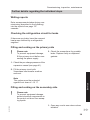
Commissioning, inspection, maintenance
Further details regarding the individual steps
Writing reports
Enter measurements taken during commissioning (described in the following)
into the reports from page 137
onwards.
Checking the refrigeration circuit for leaks
If there are any leaks, have the compact
heat pump checked by a refrigeration
engineer.
Filling and venting on the primary side
!
Please note
To prevent equipment damage,
fill the primary circuit before connecting the power supply.
3. Check the connections for possible
leaks. Replace faulty or displaced
gaskets.
1. Check the pre-charge pressure of the
expansion vessel (see page 41).
2. Fill the primary circuit with
Viessmann heat transfer medium
and vent.
Service
Note
The system must be protected
against frost down to –15 °C.
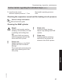
Filling and venting on the secondary side
5441 603 GB
!
Please note
To prevent equipment damage,
protect electrical components on
the control unit door from escaping liquids.
1. Open any on-site non-return valves
installed.
39
Commissioning, inspection, maintenance
Further details regarding the individual steps (cont.)
2. Check the pre-charge pressure of the
expansion vessel (see page 41).
3. Fill (flush) and vent secondary circuit:
■ Slightly open quick-action air vent
valve (see safety assembly on
page 25) (remains open).
■ To vent, move hand lever of threeway diverter valve for heating/
DHW into its centre position (see
adjacent diagram).
4.
!
Please note
To prevent equipment damage, check the flow and return
connections of the secondary
heat pump circuit for leaks.
In case of leaks, immediately
shut off the equipment, drain
the water and check the seating of the seal rings. Replace
all seal rings that may have
become dislodged.
5. Check the system pressure and top
up with water if required.
Minimum system pressure: 0.8 bar
Permissible operating pressure:
3 bar
Filling and venting the solar circuit
40
1. Check the pre-charge pressure of the
diaphragm expansion vessel.
2.
!
Please note
To prevent equipment
damage, only fill the solar circuit with Tyfocor LS.
5441 603 GB
Danger
Overheated collector areas and
overheated heat transfer medium
can cause burns/scalding and
equipment damage.
When working on the collector
and the solar circuit with heat
transfer medium, protect the collector areas against solar irradiation.
Commissioning, inspection, maintenance
Further details regarding the individual steps (cont.)
3. Vent the solar circuit.
Minimum system pressure: 1.7 bar
Permissible operating pressure:
6 bar
Checking the expansion vessel and the heating circuit pressure
Observe design information.
Vitocal technical guide
Cleaning the DHW cylinder
Danger
DHW or heat transfer medium
escaping uncontrollably can lead
to scalding and building damage.
Only open DHW and heating
water connections with an depressurised DHW cylinder.
!
Please note
Pointed or sharp cleaning
objects may damage the DHW
cylinder.
Please note
Cleaning agents containing
hydrochloric acid attack the
material of the DHW cylinder.
Please note
Negative pressure in the DHW
cylinder can lead to material
damage.
The air vent valve must always be
open when draining with a vacuum pump.
5441 603 GB
Service
!
!
41
Commissioning, inspection, maintenance
Further details regarding the individual steps (cont.)
8x
1.
AB
!
42
Please note
A short circuit between magnesium anode and internal indirect
coil increases the protective
effect of the magnesium anode
and leads to corrosion damage
on the DHW cylinder.
Before inserting the electrical
cables, measure the resistance
between terminals A and B. If
the resistance is significantly
smaller than infinite, check
whether the magnesium anode is
touching the internal indirect
coil.
5441 603 GB
2.
Commissioning, inspection, maintenance
Further details regarding the individual steps (cont.)
Replacing the magnesium anode
For removing the magnesium anode,
see page 41.
!
Please note
A short circuit between magnesium anode and internal indirect
coil increases the protective
effect of the magnesium anode
and leads to corrosion damage
on the DHW cylinder.
Before inserting the electrical
cables, measure the resistance
between terminals A and B
(see previous diagram). If the
resistance is significantly smaller
than infinite, check whether the
magnesium anode is touching
the internal indirect coil.
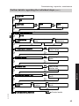
The commissioning assistant guides you
automatically through all the menus
where settings have to be made.
Please note
Incorrect operation at "Coding
level 1" can result in damage to
the appliance and heating system.
Always observe the installation
and service instructions; failure to
observe these will void your warranty rights.
5441 603 GB
!
Note
■ The scan "Start commissioning
assistant?" only appears during initial commissioning.
■ The configuration, parameter settings
and function check can also be carried
out without the commissioning assistant (see page 76, separate menu
structure and operating instructions).
■ When the unit is first commissioned,
the display is in German:
43
Service
Commissioning assistant
Commissioning, inspection, maintenance
Further details regarding the individual steps (cont.)
Sprache
Deutsch
Cesky
Dansk
English
Wählen mit
Ø
DE ç
CZ
DK
GB
5441 603 GB
■ Messages are displayed by manually
controlling some components during
commissioning. These do not indicate
appliance faults.
44
Commissioning, inspection, maintenance
Further details regarding the individual steps (cont.)
"Language
"
select
OK
"Date/Time
set
OK
"
"NO "
"Time "
set
OK
ä
"Start commissioning?
ä
OK
"Date "
set
"
"YES
"
"Programming
level 1 "
ä
OK
OK
Select parameter
group
Set
parameters
ä
ä
OK
"Temperature sensors"
ä
Display
sensor values
ä
OK
"Display signal "
ä
Display signal
inputs
ä
OK
"Actuator test
"
ä
Carry out an
actuator test
ä
"Subscriber check LON "
ä
OK
Service
ä
Carry out a subscriber
check
ä
"Functioncheck "
OK
Select
function
OK
Start function
check
ä
ä
OK
Control mode
5441 603 GB
"Commissioning finished "
45
Commissioning, inspection, maintenance
Further details regarding the individual steps (cont.)
Instructing the system user
5441 603 GB
The system installer must hand the operating instructions to the system user and
instruct him/her in the operation of the system.
46
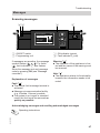
Troubleshooting
Messages
Scanning messages
DC
B
Flow temperature
Heating/cooling
DHW
Solar energy
Information
A
40℃
i
Select with
A ON/OFF switch
B Programming unit
C ON indicator (green)
D Fault indicator « (red)
If messages are pending, the message
symbol flashes ( , , ). For faults
( ), fault indictator D also flashes.
Show the message text and message
code by pressing OK (see "Message
overview").
Warning " "
■ The operation of the appliance is limited and the cause of the warning must
be removed.
Explanation of messages
Note " "
■ The appliance retains its functionality,
however the information needs to be
noted.
Service
Fault " "
■ The central fault message terminal is
activated.
■ Message via communication facility
(e.g. Vitodata, Vitocom) possible.
■ The system is no longer in standard
mode; the fault must be removed as
quickly as possible.
Acknowledging messages and recalling acknowledged messages
5441 603 GB
Operating instructions
47
Troubleshooting
Messages (cont.)
Calling up messages from the message history
■ Messages cannot be acknowledged in
the message history.
■ The messages are listed in order of
occurrence with the most recent first.
■ Up to 30 entries are stored.
Note
The service menu remains active until it
is deactivated with "Terminate service?", or if no operation takes place for
30 minutes.
Service menu:
1. Press OK + å simultaneously for
approx. 4 s.
2. "Message history"
3. Press OK to scan information about
the required message.
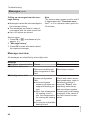
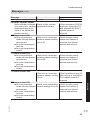
Message overview
All messages are identified by a two-digit code.
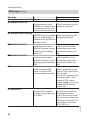
Measures
Reconfigure system.
Check and match associated parameters, reset to
delivered condition if
required ("Reset", see
operating instructions),
and reconfigure system.
Contact your local heating
contractor if the cause of
the fault cannot be remedied.
5441 603 GB
Message
System characteristics Cause
02 Std after data error
Delivered condition set
after recognition of data
fault
03 Configuration fault
System configuration
fault:
■ Incorrect system
scheme (contains nonsupported heating circuit)
■ Max. flow temperature
for heating circuit <
min. flow temperature
for cooling the heating
circuit
■ Cooling for unavailable
heating circuit
48
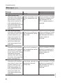
Troubleshooting
Messages (cont.)
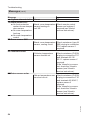
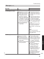
Message
System characteristics Cause
10 Outside temp sensor
Operation with outside
Short circuit, outside
temperature -40 °C
temperature sensor
5441 603 GB
20 Flow sensor secondary
Operation with temperature value of return temperature sensor in secondary circuit, plus 5 K. If
both temperature sensors (secondary flow and
return) are faulty, the
heat pump stops (message A9)
21 Return sensor sec.
Operation with temperature value of flow temperature sensor in secondary circuit, minus 5 K. If
both temperature sensors (secondary flow and
return) are faulty, the
heat pump stops (message A9)
28 Flow sensor secondary
Operation with temperature value of return temperature sensor in secondary circuit, plus 5 K. If
both temperature sensors (secondary flow and
return) are faulty, the
heat pump stops (message A9)
Check resistance (Ni 500)
at plug-in connection F0;
replace sensor if
required.
Lead break, outside tem- Check resistance (Ni 500)
perature sensor
at plug-in connection F0;
replace sensor if
required.
Short circuit, secondary
circuit flow temperature
sensor
Check resistance (Pt 500)
at plug-in connection F8
and terminals X5.8/X5.9;
replace sensor if
required.
Short circuit, secondary
circuit return temperature sensor
Check resistance (Pt 500)
at plug-in connection F9
and terminals X5.10/
X5.11; replace sensor if
required.
Lead break, secondary
circuit flow temperature
sensor
Check resistance (Pt 500)
at plug-in connection F8
and terminals X5.8/X5.9;
replace sensor if
required.
Service
18 Outside temp sensor
Operation with outside
temperature -40 °C
Measures
49
Troubleshooting
Messages (cont.)
50
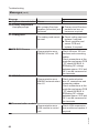
Cause
Measures
Break, secondary circuit
return temperature sensor
Check resistance (Pt 500)
at plug-in connection F9
and terminals X5.10/
X5.11; replace sensor if
required.
Short circuit, primary cir- Check resistance (Pt 500)
cuit temperature sensor, at plug-in connection F2
brine inlet
and terminals X5.2/X5.3;
replace sensor if
required.
Short circuit, primary cir- Check resistance (Pt 500)
cuit temperature sensor, at plug-in connection F3
brine outlet
and terminals X5.4/X5.5;
replace sensor if
required.
Lead break, primary flow Check resistance (Pt 500)
temperature sensor,
at plug-in connection F2
(brine inlet)
and terminals X5.2/X5.3;
replace sensor if
required.
5441 603 GB
Message
System characteristics
29 Return sensor sec.
Operation with temperature value of flow temperature sensor in secondary circuit, minus 5 K. If
both temperature sensors (secondary flow and
return) are faulty, the
heat pump stops (message A9)
30 Flow sensor primary
Operation with temperature value of return temperature sensor in primary circuit, plus 3 K. If
both temperature sensors (primary flow and
return) are faulty, the
heat pump stops (message A9)
31 Return sensor primary
Operation with temperature value of flow temperature sensor in primary
circuit, minus 2 K. If both
temperature sensors
(primary flow and return)
are faulty, the heat pump
stops (message A9)
38 Flow sensor primary
Operation with temperature value of return temperature sensor in primary circuit, plus 3 K. If
both temperature sensors (primary flow and
return) are faulty, the
heat pump stops (message A9)
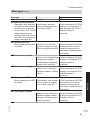
Troubleshooting
Messages (cont.)
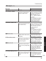
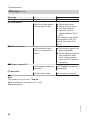
Message
System characteristics
39 Return sensor primary
Operation with temperature value of flow temperature sensor in primary
circuit, minus 2 K. If both
temperature sensors
(primary flow and return)
are faulty, the heat pump
stops (message A9)
40 Flow sensor HC2
Mixer heating circuit M2
is closed
Cause
Measures
Lead break, primary
return temperature sensor (brine outlet)
Check resistance (Pt 500)
at plug-in connection F3
and terminals X5.4/X5.5;
replace sensor if
required.
Short circuit, flow temperature sensor in heating circuit with mixer M2
Check resistance (Ni 500)
at extension kit connections for heating circuit
with mixer; replace sensor
if required.
Short circuit, system flow
temperature sensor
(downstream of heating
water buffer cylinder)
Check resistance (Pt 500)
at plug-in connection F13;
replace sensor if
required.
Short circuit, flow temperature sensor, cooling
circuit
Check resistance (Ni 500)
at plug-in connection F14;
replace sensor if
required.
43 Flow sensor system
48 Flow sensor HC2
Mixer heating circuit M2
is closed
Lead break, flow temper- Check resistance (Ni 500)
ature sensor in heating
at extension kit conneccircuit with mixer M2
tions for heating circuit
with mixer; replace sensor
if required.
4B Flow sensor system
Check resistance (Pt 500)
at plug-in connection F13;
replace sensor if
required.
5441 603 GB
Break, system flow temperature sensor (downstream of heating water
buffer cylinder)
51
Service
44 Flow sensor cooling
Troubleshooting
Messages (cont.)
Message
System characteristics Cause
4C Flow sensor cooling
Break, flow temperature
sensor, cooling circuit
Measures
Check resistance (Ni 500)
at plug-in connection F14;
replace sensor if
required.
5441 603 GB
50 DHW sensor top
DHW heating is blocked. Short circuit, top cylinder Check resistance (Pt 500)
temperature sensor
at plug-in connection F6
and terminals X6.2/X6.1;
replace sensor if
required.
54 DHW solar
No heating of the DHW
Cylinder temperature
See Vitosolic service
cylinder/primary store by sensor F6 shorted out
instructions.
the solar thermal system;
solar circuit pump
remains OFF.
58 DHW sensor top
DHW heating is blocked. Break, cylinder tempera- Check resistance (Pt 500)
ture sensor F6
at plug-in connection F6
and terminals X6.2/X6.1;
replace sensor if
required.
5C DHW solar
No heating of the DHW
Lead break, cylinder
See Vitosolic service
cylinder/primary store by temperature sensor
instructions.
the solar thermal system;
solar circuit pump
remains OFF.
60 Buffer cylinder sensor
Buffer cylinder is heated Short circuit, buffer cylin- Check resistance (Pt 500)
once every hour. Heating der temperature sensor at plug-in connection F4
stops according to set
and terminals X5.6/X5.7;
value of the return temreplace sensor if
perature sensor.
required.
52
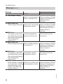
Troubleshooting
Messages (cont.)
Cause
Measures
Break, buffer cylinder
temperature sensor
Check resistance (Pt 500)
at plug-in connection F4
and terminals X5.6/X5.7;
replace sensor if
required.
Short circuit, room temperature sensor heating
circuit A1
Check remote control
sensor and replace if
required (see Vitotrol
service instructions).
Short circuit, room temperature sensor heating
circuit M2
Check remote control
sensor and replace if
required (see Vitotrol
service instructions).
Short circuit, room temperature sensor, cooling
circuit
Check resistance (type Ni
500) at plug-in connection
F16; replace sensor if
required.
Check remote control
sensor and replace if
required (see Vitotrol
service instructions).
5441 603 GB
78 Room sensor HC1
■ No frost protection
Break, room temperature
mode via room temper- sensor heating circuit A1
ature sensor
■ No room temperature
hook-up
■ No room temperature
control
Service
Message
System characteristics
68 Buffer cylinder sensor
Buffer cylinder is heated
once every hour. Heating
stops according to set
value of the return temperature sensor.
70 Room sensor HC1
■ No frost protection
mode via room temperature sensor
■ No room temperature
hook-up
■ No room temperature
control
71 Room sensor HC2
■ No frost protection
mode via room temperature sensor
■ No room temperature
hook-up
■ No room temperature
control
73 Room sensor SKK
53
Troubleshooting
Messages (cont.)
Message
System characteristics
79 Room sensor HC2
■ No frost protection
mode via room temperature sensor
■ No room temperature
hook-up
■ No room temperature
control
7B Room sensor SKK
Cause
Measures
Break, room temperature Check remote control
sensor heating cirsensor and replace if
cuit M2
required (see Vitotrol
service instructions).
Break, room temperature Check resistance (type Ni
sensor, cooling circuit
500) at plug-in connection
F16; replace sensor if
required.
92 Collector sensor
Collector temperature
sensor shorted out.
Check resistance (Pt 500)
at plug-in connection F21
and terminals X6.10/
X6.11; replace sensor if
required.
If the Vitosolic is connected, check the Vitosolic
sensor (see Vitosolic
service instructions).
93 Return sensor solar
5441 603 GB
Return temperature sen- Check resistance (Pt 500)
sor short circuit
at plug-in connection F18
and terminals X6.6/X6.7;
replace sensor if
required.
If the Vitosolic is connected, check the Vitosolic
sensor (see Vitosolic
service instructions).
54
Troubleshooting
Messages (cont.)
Message
System characteristics Cause
9A Collector sensor
Collector temperature
sensor lead broken
Measures
Check resistance (Pt 500)
at plug-in connection F21
and terminals X6.10/
X6.11; replace sensor if
required.
If the Vitosolic is connected, check the Vitosolic
sensor (see Vitosolic
service instructions).
9B Return sensor solar
Return temperature sen- Check resistance (Pt 500)
sor lead broken,
at plug-in connection F18
and terminals X6.6/X6.7;
replace sensor if
required.
If the Vitosolic is connected, check the Vitosolic
sensor (see Vitosolic
service instructions).
A4 Check valve
Solar check valve stuck
or faulty
Check the check valve
and replace, if required.
A6 Secondary pump
A7 Solar circuit
No flow in solar circuit
(solar circuit pump stopped)
Check voltage at connection 212.4 and check solar
circuit pump; replace if
required (see Vitosolic
installation and service
instructions).
5441 603 GB
A8 Pump heating circuit 1
No flow in heating circuit Test voltage at connection
A1 (circuit pump stop212.2 and check pump
ped)
mechanically; replace if
required.
55
Service
No flow in secondary cir- Check voltage at conneccuit (secondary circuit
tion 211. 2 and check secpump stopped)
ondary pump mechanically; replace if required.
Troubleshooting
Messages (cont.)
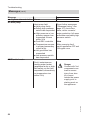
Measures
Scan further messages
("Message history" see
page 47); check flow
rates, motor currents/
motor protection, full wave
soft starter and safety high
pressure switch.
Note
After removing fault,
switch appliance OFF and
ON again once.
Danger
Contact with 'live'
components can
lead to severe
injury from electric current.
Isolate the power
supply prior to
starting work on
the appliance.
5441 603 GB
Message
System characteristics Cause
A9 Heat pump
Heat pump fault
■ Heat pump faulty
■ Safety high pressure
switch has responded
■ High pressure or low
pressure sensor has
responded 8 times
within 24 h
■ Fault EEV controller
■ Temperature sensors
in primary/secondary
circuit faulty
■ Hot gas klixon has
responded
■ Low pressure switch
has responded
AB Electric heater
Fault, instantaneous
heating water heater
(appliance faulty or high
limit safety cut-out has
responded; alternatively
no temperature rise
within 24 h)
56
Troubleshooting
Messages (cont.)
Message
System characteristics Cause
Measures
■ Check power supply,
power cable and plug to
the instantaneous heating water heater
■ Test instantaneous
heating water heater
control signal at connections 211.3; check
high limit safety cut-out
and reset if required;
check instantaneous
heating water heater.
Installation
instructions,
instantaneous
heating water
heater
B4 A-D converter
Internal fault ADC (analogue digital converter,
reference), ribbon cable
between sensor PCB
and main PCB faulty, or
PCBs faulty
Check sensor connections F1, F5, F10, F15,
F19 and F22 on the controller and sensor circuit
board.
Internal error EEPROM
Replace coding card.
Communication error KM BUS solar control
unit, or sensor S3 of
Vitosolic faulty
■ Check parameter
"Solar collector".
■ Check connection to
Vitosolic.
■ Check sensor S3 and
replace, if required (see
Vitosolic installation
and service instructions).
5441 603 GB
B9 KM BUS solar
57
Service
B5 EEPROM
Troubleshooting
Messages (cont.)
Message
System characteristics Cause
BA KM BUS mixer HC
Communication fault,
KM BUS or internal fault
in extension set for one
heating circuit with mixer
BB KM BUS mixer cooling
KM BUS communication
error or internal fault in
extension kit, NC-Box for
cooling circuit
BC KM BUS R/C HC1
Communication error KM BUS remote control;
heating circuit without
mixer A1
BD KM BUS R/C HC2
Communication error KM BUS remote control;
heating circuit with mixer
M2
BF Communication module
LON communication
error; incorrect LON
communication module
Measures
Check extension kit connections and code.
Check connections and
parameter settings.
Check remote control
connections and code;
switch ON remote control.
Check remote control
connections and code;
switch ON remote control.
Check connections and
type of LON communication module.
If required, replace in the
following order: Cross
connect PCB, ribbon
cables between the cross
connect PCB and the
main PCB
C5 Power-OFF
5441 603 GB
Power-OFF enabled
No measures required.
(triggered by power sup- If message persists:
ply utility)
Check the connection at
the controller and sensor
PCB first at terminal X3.7
(feed) then at terminal
X3.6 (230 V~).
58
Troubleshooting
Messages (cont.)
Message
System characteristics Cause
C9 Refrigerant circuit
Refrigerant circuit fault:
■ Safety high pressure
switch has activated
■ Compressor motor
protection (thermal
relay) has responded
(if installed: Full wave
soft starter or separate
compressor motor protection has responded)
■ Hot gas klixon has
responded
Measures
■ Check flow and return
temperature sensors in
primary and secondary
circuits.
■ Check primary and secondary circuits for pressure and throughput
(see also message A9).
■ Have heat pump tested
by a refrigeration engineer.
The switching signal can
be tested at connection
215.4 (230 V~) of the main
PCB.
Note
After removing fault,
switch appliance OFF and
ON again once.
5441 603 GB
Primary circuit fault:
■ Check safety equip■ Primary circuit presment on cross connect
sure switch/frost proPCB terminals X3.9 and
tection monitoring has
X3.8; in systems withresponded
out safety equipment,
■ Primary pump thermal
check jumper between
motor protection
X3.9/X3.8.
■ Check connection at
terminals 26.1/26.2
(jumper fitted in the
delivered condition,
plug sH is located in the
cable trunking at the
control unit front).
The switching signal can
be tested at connection
215.3 (230 V~).
59
Service
CA Primary source
Troubleshooting
Messages (cont.)
Message
System characteristics Cause
CB Primary temperature
Heat pump stops
Min. primary flow temperature (brine inlet) not
achieved
CC Coding card
The coding card cannot
be read
Measures
■ Primary circuit flow temperature too low, no
measures required
■ Check coding card and
replace if required.
■ Check controller and
sensor PCB and
replace, if required.
CD KM BUS Vitocom
Communication error KM BUS Vitocom 100
Check Vitocom 100 connections and connecting
cables.
Check connections at the
controller and sensor PCB
aVG check KM BUS. A
fluctuating DC voltage
between approx. 20 V and
30 V can be measured at
the terminals.
Communication error KM BUS external extension H1
Check external extension H1 connections and
connecting cables.
Check connections at the
controller and sensor PCB
aVG check KM BUS. A
fluctuating DC voltage
between approx. 20 V and
30 V can be measured at
the terminals.
Communication error LON module in control
unit
Check LON communication module and replace if
required.
CE KM BUS ext. extension
5441 603 GB
CF Communication module
60
Troubleshooting
Messages (cont.)
Message
System characteristics Cause
Measures
D1 Compressor
Compressor fault:
■ Reset compressor therThermal compressor
mal relay, check setting,
relay or safety element of
restore delivered condifull wave soft starter (if
tion ("Standard setinstalled) has respontings", see menu strucded.
ture).
Separate compressor
■ Check compressor
motor protection (if
electrical connections,
installed) has respontest coil resistance of
ded.
compressor motor.
Check compressor
phase sequence.
■ The switching signal
(from the thermal relay,
full wave soft starter or
a separate motor overload protection) can be
tested at connection
215.3 (230 V~).
■ If required, replace full
wave soft starter (if
installed); have compressor checked by a
refrigeration engineer.
5441 603 GB
D3 Low pressure
Low pressure fault
■ Heat pump faulty
■ Primary pump faulty
■ Low pressure switch
has responded or is
faulty
■ Have heat pump tested
by a refrigeration engineer.
The signal can be tested
at connection 215.5
(230 V~).
61
Service
Note
If overheating occurs,
internal motor protection
prevents a re-enabling of
the compressor for 1-3
hours.
Troubleshooting
Messages (cont.)
Message
System characteristics Cause
D6 Flow switch
Well circuit flow switch
cannot detect a flow
Measures
■ Check well pump.
■ Check primary circuit.
■ If no flow switch is
installed, insert a
jumper between X3.3/
X3.4.
The signal can be tested
at connection 216.3 or
across terminals X3.3/
X3.4.
E0 LON subscriber
LON subscriber has
failed or connection is
faulty
■ Call up fault memory at
faulty subscriber.
■ Check address (system
and subscriber numbers); check connections and LON connecting cables.
Compressor output not
selected
Set "Output" parameter
accordingly.
Control unit restart
No measures required.
F2 Param. output 1/2
FF New start
5441 603 GB
Note
The system is out of use if "Simulation" is displayed. Connection F11 must
not be assigned.
62
Troubleshooting
Diagnosis (service scans)
Calling up diagnosis
Service menu:
1. Press OK + å simultaneously for
approx. 4 s.
2. "Diagnosis"
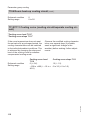
3. Select required area, e.g. "Heat
pump"
Scanning operating data
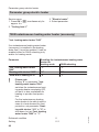
Operating data can be scanned in the following areas:
"System overview"
For further information, see page 63
"System"
For further details, see menu structure
"Heating circuit 1"
For further details, see menu structure
"Heating circuit 2"
If a heating circuit with mixer M2 is installed, see the
menu structure for further details
"Cooling circuit SKK"
If a separate cooling circuit is installed, see the menu
structure for further details
"DHW"
For further details, see menu structure
"Solar"
If a solar thermal system is installed, see the menu
structure for further details
"Heat pump"
For further information, see page 66
"Temperature sensors"
For further details, see menu structure
"Signal inputs"
For further details, see menu structure
"Brief scan"
For further information, see page 66
Service
Note
Only connected temperature sensors
are displayed. In case of faults, the display shows "- - -".
System overview
5441 603 GB
Service menu:
1. Press OK + å simultaneously for
approx. 4 s.
2. "Diagnosis"
3. "System overview"
Note
The display depends on the system version (e.g. column H: Display only if
heating circuit M2 is installed).
With some components the symbols
move when they are operational (e.g.
pumps).
The values shown are examples.
63
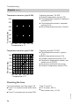
Troubleshooting
Diagnosis (service scans) (cont.)
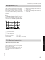
A
B C D E F G H K L
Ü System overview
1
0
3
7
1
45
41
Ç
è1 è2
20
18
15
10
50 50 45 21 22
33 21 22
44
32
29 45
38 38
51
G
N
Back with
ä
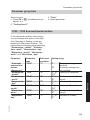
A to L For an explanation of the contents of columns A to L,
see the following tables.
Columns C and K and not
assigned.
Natural cooling function
N
(
)
The arrow points at the heating/cooling circuit activated
for cooling.
O
Geothermal probe symbol
A
0
3
5441 603 GB
7
Outside temperature sensor
Outside temperature
Primary circuit flow temperature
(brine inlet temperature)
Primary circuit return temperature (brine outlet temperature)
64
Troubleshooting
Diagnosis (service scans) (cont.)
1
45
41
51
F
Refrigerant circuit (compressor
stage 1)
Instantaneous heating water
heater (at stage 1)
Secondary circuit flow temperature
Secondary circuit return temperature
Secondary pump
Hot gas temperature
Compressor
Primary pump (primary source)
D
50
29
Solar circuit
Collector temperature (collector
temperature sensor)
Solar return temperature (cylinder temperature sensor)
or
DHW temperature sensor solar
cylinder (connected to the
Vitosolic)
Solar circuit pump
45
33
44
G
1
21
21
38
H
2
22
22
33
38
E
50
45
DHW
DHW temperature, top
Set DHW temperature
Circulation pump for cylinder
heating
DHW circulation pump
Heating circuit A1 (without
mixer)
Room temperature
Set room temperature
Set heating circuit flow temperature
Heating circuit pump
Heating circuit with mixer M2
Room temperature
Set room temperature
Heating circuit flow temperature
Set heating circuit flow temperature
Heating circuit pump
Mixer
L
20
18
15
10
5441 603 GB
Heating water buffer cylinder
Heating water buffer cylinder
temperature
Set temperature, heating water
buffer cylinder
System flow temperature
System flow
Swimming pool
Swimming pool circuit pump
Separate cooling circuit
Room temperature
Set room temperature
Flow temperature, separate cooling circuit
Flow temperature, separate cooling circuit, set value
"Cooling circuit pump": NC signal
Mixer
65
Service
B
1
Troubleshooting
Diagnosis (service scans) (cont.)
Heat pump module diagnosis
As part of the heat pump module diagnosis, the compressor hours run can be scanned for different load classes.
A load class specifies the compressor operation at a certain differential of evaporation
and condensation temperature ΔTV/K.
Compressor runtime (hours run
according to load classes)
Ü Runtime compressor
h
Runtime
Select with
1
?
3
4
5
230h
(
Load class
Service menu:
1. Press OK + å simultaneously for
approx. 4 s.
2. "Diagnosis"
3. "Heat pump"
4. "Runtime compressor"
The compressor hours run ("Hours
run") can be scanned with for every
"Load class".
Assigning the load classes:
Load class
Hours run for ΔTV/K
1
ΔTV/K < 25 K
2
25 K < ΔTV/K < 32 K
3
32 K < ΔTV/K < 41 K
4
41 K < ΔTV/K < 50 K
5
ΔTV/K > 50 K
ΔTV/K Differential, evaporation and condensation temperature
Brief scan
In the brief scan, you can scan temperatures, software versions and connected components, for example.
Ü Brief scan
1:
1
F
0
A
1
2
2:
0
0
0
0
0
0
3:
4:
0
0
0
0
0
0
0
0
0
0
0
0
Select with
66
(
5441 603 GB
Service menu:
1. Press OK + å simultaneously for
approx. 4 s.
2. "Diagnosis"
3. "Brief scan"
Troubleshooting
5441 603 GB
For an explanation of the relevant values in the individual lines, see the following table:
Line (brief
Field
scan)
1
2
3
4
5
6
1
Control unit:
Device: Version
Coding card: Version
Software version (SW Coding card: ID Low
index)
2
System scheme
Number Common demand temperature
of KM
BUS
users
3
0
Program- ExtenSolar con- LON
External
ming unit: sion for
trol unit:
module:
extension:
Software heating
Software Software Software
index
circuit
version
version
version
with
mixer:
Software
version
4
0
0
0
0
Appliance type
5
0: no
0: no
0
External 0 to 10 V hook-up
external
external
Display in %
demand
blocking
0: no external hook-up
1: exter1: external
nal blockdemand
ing
6
Number of LON sub- Check
0
0
0
scribers
digit
7
Remote control:
Heating circuit with- Heating circuit with
out mixer A1:
mixer M2
0 w/o
Software 0 w/o
Software 0
0
1 Vitotrol version
1 Vitotrol version
200
200
8
EEV module 1:
EEV module 1:
Extension for heating
Hardware index
Software index
circuit with mixer for
separate cooling circuit:
Software version
67
Service
Diagnosis (service scans) (cont.)
Troubleshooting
Diagnosis (service scans) (cont.)
Line (brief
scan)
9
10
Field
1
2
0
0
Control unit:
Software version
High
3
4
0
0
Control unit:
Software version
Low
5
6
0
0
Programming unit:
Software version
Testing outputs (actuator test)
■ Only actuators are shown that correspond to the actual system equipment
level.
■ Activating the actuator test switches all
actuators to zero volt.
■ One or several actuators can be started from this menu.
■ The actuator test stops automatically
after approx. 30 min or with .
■ With "System overview" and the
diagnosis page "EEV module" can be
called up, without exiting the actuator
test. Back to the actuator test display
with OK.
Service menu:
1. Press OK + å simultaneously for
approx. 4 s.
2. "Actuator test"
Note
■ If a cylinder primary pump is controlled
via the PWM signal, activate both outputs "Cylinder prim pump".
■ All actuators can be switched off simultaneously with "All actuators".
Function check
To test the function of connected components (see commissioning assistant,
page 43).
3. "Function check"
4. Select required group, e.g. "DHW".
5441 603 GB
Service menu:
1. Press OK + å simultaneously for
approx. 4 s.
2. "Service functions"
68
Troubleshooting
Function check (cont.)
"Function check" menu
Function
Heating circuit 1
Heating circuit 2
Separate cooling circuit
DHW (DHW cylinder)
Swimming pool
Electric heater (instantaneous heating water heater,
accessory)
Heat pump
Solar
System characteristics
Secondary pump and heating circuit pump A1 are
started.
Heating circuit pump M2 starts. Open/close mixer
every 5 min.
Primary pump and circulation pump, separate cooling
circuit are started. Open/close mixer every 5 min.
Secondary pump, circulation pump for cylinder heating (heating water side) and cylinder primary pump
(DHW side) are started.
Secondary pump is started. Swimming pool output is
switched on/off every minute.
Secondary pump is started. Instantaneous heating
water heater regulates to a flow temperature of
30 °C.
Primary pump and secondary pump are started. Heat
pump regulates to a return temperature of 30 °C.
Solar circuit pump starts.
Note
If the Vitosolic is connected, only the display for the
solar circuit pump is activated in the system overview.
Start the solar circuit pump via the Vitosolic (see
Vitosolic service instructions).
The primary pump starts. The primary circuit flow
temperature is averaged every minute.
Note
The execution of this function Note
lasts 10 min.
This function determines the temperature of the
undisturbed ground.
If the function is terminated earlier, the average value
calculated at the time of the termination is saved.
5441 603 GB
Steps if the room temperature is too low
1. Vent the heating circuits.
69
Service
Primary source
Troubleshooting
Steps if the room temperature is too low (cont.)
2. Check throughput of affected heating
circuits. Recommended temperature
differential between heating flow and
return approx. 8 K.
5. Increase the set room temperature
for standard mode and match the
heating curves.
Operating instructions
3. Hydraulically balance the connected
heating circuits.
4. Check the outside temperature sensor (see page 73).
6. Enable heating operation via the integral instantaneous heating water
heater (if installed) (see page 96).
No display indication on the programming unit
1. Switch ON system ON/OFF switch.
2. Check heat pump control unit fuse;
replace if required (see page 74).
5. Replace programming unit if
required.
6. Replace PCB 2 (main PCB) if
required.
5441 603 GB
3. Check whether there is power at the
control unit; switch ON power supply
if required.
4. Check the plug-in and threaded connections.
70
Troubleshooting
Repairs
Overview of internal components
%
M
a
g]
c
a:C]
K
lJ
A
aS
sH
aYNAaYNS
sG
Service
aJ
H
?
G
aYND
kK C D aYNF F
5441 603 GB
aYNG
B aYNH
71
Troubleshooting
Repairs (cont.)
?
%
%a
aS
aJ
sG
sH
kK
lJ
a:Dc
A
B
C
D
F
G
H
K
M
Cylinder primary pump
Primary circuit air vent valve
Condenser drain valve
Schrader high pressure valve
Primary pump drain valve
Drain valve on the secondary side
Pipe / position instantaneous
heating water heater
Schrader low pressure valve
Drain & fill valve, DHW cylinder
Non-return valve
5441 603 GB
aYH
Secondary circuit flow temperature sensor (alternative positions)
Cylinder temperature sensor
Solar circuit return temperature
sensor
Primary circuit flow temperature
(heat pump brine inlet)
Secondary circuit, return temperature sensor
Secondary pump
Primary pump
Compressor
Three-way diverter valve heating/
DHW
Connection at terminals:
1, 2 Hot gas temperature sensor
3, 4 Low pressure sensor
5, 6 Safety high pressure sensor
72
Troubleshooting
Repairs (cont.)
Positions cylinder drain & fill valve
A
B
C
C Drain & fill valve, cylinder, open to
drain or fill the cylinder
Draining the heat pump on the secondary side
1. Close on-site drain & fill valve.
2. Drain heat pump at secondary flow
drain valve (see page 71).
Checking sensors
For the position of the sensors in the heat
pump, see figure on page 71.
5441 603 GB
For sensor connections to the controller
and sensor PCB, see page 127.
73
Service
A Drain & fill valve, cylinder, closed
B Drain & fill valve, cylinder, open to
drain the internal DHW line
Troubleshooting
Repairs (cont.)
Temperature sensors type Ni 500
640
600
560
Capturing element: "Ni 500"
■ Outside temperature sensor (F0)
■ Flow temperature sensors, heating circuits M2 (F12)
■ Flow temperature sensor, separate
cooling circuit
■ Room temperature sensors (Vitotrol)
520
Resistance in
480
440
400
20
-40 -20
0
Temperature in °C
40
60
Temperature sensors type Pt 500
860
780
Resistance in
700
620
Capturing element "Pt 500"
■ Flow temperature sensor, system
(F13)
■ Buffer temperature sensor (F4)
■ Cylinder temperature sensor (F6)
■ Flow/return temperature sensor, secondary circuit (F8/F9)
■ All sensors inside the heat pump
■ Collector temperature sensor (F21)
540
460
-20 20 60 100 140 180
Temperature in °C
Checking the fuse
Fuse F1 and F3:
■ 6.3 A (slow), 250 V~
■ Max. power loss ≤ 2.5 W
5441 603 GB
For fuse locations, see from page 119:
■ Fuse F1 is located on the luster terminals.
■ Fuse F3 is located on the main PCB.
74
Troubleshooting
Repairs (cont.)
Danger
Contact with 'live' components
can lead to severe injury from
electric current.
Before working on the equipment, always ensure that the
power circuit is also at zero
volt.
Removing the fuse does not
switch the power circuit to zero
volt.
Appliance too noisy
Possible causes:
■ Transport locking bracket not
removed: See page 22.
■ Control unit door not tightly sealed:
See page 20.
■ Secondary circuit return line A
touches the primary circuit return line
B or other lines or the compressor.
A
5441 603 GB
Service
B
75
Control unit settings by the contractor
Control unit settings by the contractor
The following pages only describe those
parameters that can only be adjusted by
specialists operating in the service menu
at "Coding level 1".
Customer level parameters that are
described in the operating instructions
are not explained here.
!
Note
The available parameters depend on the
individual system configuration (e.g.
parameters for heating circuit M2: display only if heating circuit M2 is configured).
Please note
Incorrect operation at "Coding
level 1" can result in damage to
the appliance and heating system.
Always observe the installation
instructions; failure to observe
these will void your warranty
rights.
Activating service menu
The service menu can be activated from
any menu.
Press OK + å simultaneously for
approx. 4 s.
Disabling the service menu
The service menu remains active until it
is deactivated with "Terminate service?", or if no operation takes place for
30 minutes.
To set a parameter, first select the
parameter group and then the parameters.
All parameters are displayed as plain
text. A parameter code is also assigned
to each parameter.
76
Service menu:
1. Press OK + å simultaneously for
approx. 4 s.
2. Select "Coding level 1".
3. Select parameter group: "System
definition"
4. Select parameter: "System scheme
7000"
5. Adjust system scheme: "2"
5441 603 GB
Setting parameters, using the example "System scheme"
Control unit settings by the contractor
Control unit settings by the contractor (cont.)
Alternatively, if the service menu was
already activated:
Extended menu
1. å
2. "Service"
3. Select "Coding level 1".
4. Select parameter group: "System
definition"
5. Select parameter: "System scheme"
6. Confirm parameter code: "7000"
7. Select language: "2"
Note
The parameters shown depend on the
current device settings.
Reinstating the delivered condition (Reset)
5441 603 GB
Service
Service menu:
1. Press OK + å simultaneously for
approx. 4 s.
2. "Coding level 1"
3. "Standard setting"
4. "All groups"
or
Select required parameter group (e.g.
"System definition").
77
Parameter group system definition
Parameter group system definition
Service menu:
1. Press OK + å simultaneously for
approx. 4 s.
2. "Coding level 1"
3. "System definition"
4. Select parameter.
7000 System scheme
"System scheme 7000"
Adjust the system scheme during commissioning according to the system version. 12 different system schemes are
available (see technical guide).
Setting
0
1
2
3
4
5
6
7-10
11
Heating circuit without mixer A1
—
X
X
—
—
X
X
Do not adjust.
External control
Delivered condition
Setting
The components associated with the
corresponding system scheme are automatically enabled and monitored.
Heating circuit with
mixer M2
—
—
—
X
X
X
X
DHW heating
X
—
X
—
X
—
X
2
0 to 11
7001 Language
Note
Adjust only in the extended menu.
Operating instructions
5441 603 GB
Language for operating and display elements in the control unit.
78
Parameter group system definition
7003 Temperature differential for the heating limit
"Temperature differential heating 7003"
Temperature differential for calculating
the heating limit.
Heating limit: Set room temperature
minus "Temperature differential heating"
If the average outside temperature calculated over 3 hours falls below the heating limit, central heating starts.
Example:
The selected set room temperature is
20 °C; the value set under "Temperature differential heating" is 4 K.
This results in a heating limit of 16 °C (20
°C – 4 K).
Central heating commences if the average outside temperature drops below
16 °C (heating limit).
If the average outside temperature
exceeds 18 °C, central heating stops
(because of the specified hysteresis of
2 K).
Delivered condition
Setting range
20°C
18°C
16°C
2K
t
A Set room temperature
B Adjusted outside temperature
C Selected value "Temperature differential heating"
D Heating mode OFF
E Heating mode ON
40 (≙ 4 K)
0 to 200 (≙ 0 to 20 K)
Service
7004 Temperature differential for the cooling limit
5441 603 GB
"Temperature differential cooling 7004"
Temperature differential for calculating
the cooling limit.
Cooling limit: Set room temperature plus
"Temperature differential cooling"
If the average outside temperature calculated over 3 hours exceeds the cooling
limit, room cooling is switched on.
Example:
The selected set room temperature is
20 °C; the value set under "Temperature differential cooling" is 4 K.
This results in a cooling limit of 24 °C (20
°C + 4 K).
Room cooling commences if the average
outside temperature rises above 24 °C
(cooling limit).
79
Parameter group system definition
7004 Temperature differential for the cooling… (cont.)
Room cooling stops if the average outside temperature falls below 23 °C
(because of the specified hysteresis of
1 K).
Delivered condition
Setting range
Note
This parameter is only available if cooling mode has been enabled via parameter "Cooling" (see page 110).
40 (≙ 4 K)
10 to 200 (≙ 1 to 20 K)
7010 External extension
"External extension 7010"
Enabling external extension H1.
External extension H1 can be used for
the following hook-ups/components:
■ Swimming pool water heating
■ External operating mode changeover
■ External demand
■ External mixer OPEN
■ External blocking
■ External mixer CLOSE
Valu Explanation
e
"1"
External extension H1 is installed
and enabled.
"0"
External extension H1 is not enabled.
Delivered condition
Setting
0
1/0
Note
Only one external extension can be connected to the control unit.
If the components for swimming pool
heating are connected to "External
extension H1", no additional hook-up
(e.g. operating mode changeover) can
be connected to the "External extension
H1".
7008 Swimming pool
5441 603 GB
"Swimming pool 7008"
80
Parameter group system definition
7008 Swimming pool (cont.)
Swimming pool heating
Valu Explanation
e
"1"
Swimming pool is connected and
will be heated.
"0"
Swimming pool will not be
heated.
Note
The thermostat for swimming pool temperature control is connected to the control unit via external extension H1. Set
parameter "External extension" to "1"
(see page 80), otherwise the "Swimming pool" parameter will not be displayed.
Delivered condition
Setting
0
1/0
7011 External operating mode changeover
Note
Only in conjunction with external extension H1.
Setting which system components the
operating mode is changed over for
when signal "Operating mode" is issued
(signal active when the contact is closed,
see summary of PCB from page 119).
With the external operating mode
changeover a heating circuit, for example, can be switched via a Vitocom from
the operating mode "Reduced" to "Normal".
5441 603 GB
Setting
0
1
2
3
4-15
16
Heating circuit
without mixer
A1
—
X
—
X
Do not adjust.
—
Note
■ The signal "External blocking" has a
higher priority than the signal "External
demand".
■ The function via parameter "External
demand mixer "OPEN" 7014" has a
higher priority than the function via
parameter "Changing the heating
circuit operating mode 7011".
■ In the parameters "Effect of operating mode changeover 7012" and
"Duration of operating mode
changeover 7013" also set the
required operating mode and the
changeover duration.
Heating circuit
with mixer M2
DHW heating
Heating water
buffer cylinder
—
—
X
X
—
—
—
—
—
—
—
—
—
X
—
81
Service
"Changing the heating circuit operating mode 7011"
Parameter group system definition
7011 External operating mode changeover (cont.)
Setting
17
18
19
20-31
32
33
34
35
36-47
48
49
50
51
52-63
Heating circuit
without mixer
A1
X
—
X
Do not adjust.
—
X
—
X
Do not adjust.
—
X
—
X
Do not adjust.
Delivered condition
Setting range
Heating circuit
with mixer M2
DHW heating
Heating water
buffer cylinder
—
X
X
X
X
X
—
—
—
—
—
X
X
—
—
—
—
X
X
X
X
—
—
X
X
X
X
X
X
X
X
X
X
0
0 to 63
7012 Operating mode for external operating mode changeover
"Effect of operating mode changeover 7012"
Note
Only in conjunction with external extension H1.
Operating modes
Operating instructions
Value
"0"
"1"
82
Operating mode (see operating instructions)
Heating
DHW
"Standby"
"OFF"
"Reduced"
"Top"
5441 603 GB
Setting the operating mode that is enabled with the external operating mode
changeover (see also "Changing the
heating circuit operating mode
7011").
Parameter group system definition
7012 Operating mode for external operating mode… (cont.)
Value
"2"
"3"
Operating mode (see operating instructions)
Heating
DHW
"Normal"
"Normal"
"Fixed value"
"Temperature 2"
(see set flow temperature on
page 102)
Delivered condition
Setting range
2
0 to 3
7013 Duration of external operating mode changeover
"Duration of operating mode changeover 7013"
Note
Only in conjunction with external extension H1.
5441 603 GB
Service
Setting the minimum duration of external operating mode changeover (see
also "Changing the heating circuit
operating mode 7011"). After expiry,
the control unit switches back to the
operating mode that was enabled before
the external operating mode changeover. This also occurs if party mode was
enabled in the meantime.
83
Parameter group system definition
7013 Duration of external operating mode… (cont.)
Example:
The diagram shows the duration of external operating mode changeover B,
subject to signal duration A, with
parameter "Duration of operating
mode changeover 7013" set to 8 h
(delivered condition).
The external operating mode changeover is enabled for at least 8 h (delivered
condition), independent of the length of
the signal. If the signal lasts for longer
than 8 h, the external operating mode
changeover remains enabled for as long
as the signal is present.
A
B
8h
A
B
8h
A
B
8h
Value
"0"
"1" to "12"
Duration
Changeover is only carried out as long as signal "External demand /
mixer OPEN" is available.
Duration of the operating mode changeover in hours, starting with
the activation of the external operating mode changeover.
8h
0 to 12 h
5441 603 GB
Delivered condition
Setting range
84
Parameter group system definition
7014 External demand mixer "OPEN"
"External demand mixer "OPEN" 7014"
Note
Only in conjunction with external extension H1.
Setting for the way the signal "External
demand" is to affect the heat pump (signal active when the contact is closed;
see summary of PCBs from page 119).
Setting
0
1
2-3
4
5
6-7
Note
■ The signal "External blocking" has a
higher priority than the signal "External
demand".
■ See also "Set flow temperature, external demand" on page 102.
Heating circuit with mixer
M2
Control mode
Mixer "Open"
Do not adjust.
Control mode
Mixer "Open"
Do not adjust.
Delivered condition
Setting range
Heat demand to the heat
pump
No
No
Yes
Yes
4
0 to 7
7015 External blocking mixer "CLOSED"
Note
Only in conjunction with external extension H1.
Setting for how the signal "External
blocking" is to affect the heat pump (signal active when contact is closed; see
summary of PCBs from page 119).
5441 603 GB
!
Note
■ The signal "External blocking" has a
higher priority than the signal "External
demand".
■ See also parameter "Set flow temperature for external demand" on
page 102.
Please note
The system may no longer be
protected against frost.
85
Service
"External blocking mixer "CLOSED" 7015"
Parameter group system definition
7015 External blocking mixer "CLOSED" (cont.)
Setting
0
1
2-3
4
5
6-7
Heating circuit with mixer
M2
Control mode
Mixer "Close"
Do not adjust.
Control mode
Mixer "Close"
Do not adjust.
Delivered condition
Setting range
Heat pump blocking
No
No
Yes
Yes
4
0 to 8
7017 Vitocom 100
"Vitocom 100 7017"
Using the Vitocom 100 communication
interface.
Delivered condition
Setting
0
1/0
Valu Explanation
e
"1"
Vitocom 100 is installed and enabled.
"0"
Vitocom 100 is not used.
701B Common system temperature sensor
In systems with a heating water buffer
cylinder, a common flow temperature
sensor ("System flow temperature sensor") can be installed in the heating water
flow, downstream of the heating water
buffer cylinder.
86
Valu Explanation
e
"1"
System flow temperature sensor
is installed and enabled.
"0"
System flow temperature sensor
is not used. The flow temperature
sensor for the secondary circuit is
not used.
5441 603 GB
"Common system sensor 701B"
Parameter group system definition
701B Common system temperature sensor (cont.)
1
1/0
5441 603 GB
Service
Delivered condition
Setting
87
Parameter group compressor
Parameter group compressor
Service menu:
1. Press OK + å simultaneously for
approx. 4 s.
2. "Coding level 1"
3. "Compressor"
4. Select parameter.
5000 Enable compressor
"Enable 5000"
Enabling the compressor stage.
Note
Never block the heat pump compressor
in standard mode.
Valu Explanation
e
"1"
Compressor stage is used.
"0"
Compressor stage is not used,
e.g. in case of a fault.
Delivered condition
Setting
1
1/0
5030 Heat pump output
"Output compressor stage 5030"
Type-dependent heating output of heat
pump.
Delivered condition
Specified via coding card according to rated heating output
of heat pump (e.g. 8 kW for type 108; see type plate for
rated heating output)
1 to 255 kW
5441 603 GB
Setting range
This value is required to calculate the
energy statement and seasonal performance factor.
88
Parameter group DHW
Parameter group DHW
Service menu:
1. Press OK + å simultaneously for
approx. 4 s.
2. "Coding level 1"
3. "DHW"
4. Select parameter.
6000 Set cylinder temperature
"Cylinder temperature DHW 6000"
DHW cylinder set temperature for DHW
heating.
Operating instructions
Note
If the heat pump alone cannot achieve
the set DHW temperature, the instantaneous heating water heater (accessory)
is also started (if enabled via parameter
"DHW with e heating 6015").
Delivered condition
Setting range
500 (≙ 50 °C)
100 to 700 (≙ 10 to 70 °C)
6015 DHW reheating
Note
■ The instantaneous heating water
heater (accessory) has to be enabled
separately with parameter "Inst. heating water heater 7900".
■ Observe setting for "Booster heater
hysteresis 6008".
5441 603 GB
DHW reheating enabled via instantaneous heating water heater (accessory).
If the set cylinder temperature cannot be
achieved with the heat pump, an instantaneous heating water heater (accessory) can be used.
89
Service
"DHW with e heating 6015"
Parameter group DHW
6015 DHW reheating (cont.)
Valu Explanation
e
"1"
Instantaneous heating water
heater (accessory) is connected
and enabled for DHW reheating.
"0"
Instantaneous heating water
heater (accessory) is not enabled
for DHW reheating.
Delivered condition
Setting
1
1/0
6005 Minimum temperature for DHW cylinder
"Minimum temperature 6005"
Lower set temperature for DHW cylinder
(minimum temperature).
When the actual temperature falls below
the minimum temperature selected, the
DHW cylinder is heated up to that value
plus hysteresis (frost protection). This is
independent of the selected operating
programme.
Delivered condition
Setting range
The temperature for this is always captured by the top cylinder temperature
sensor.
100 (≙ 10 °C)
50 to 600 (≙ 5 to 60 °C)
6006 Maximum temperature for DHW cylinder
"Maximum temperature 6006"
Delivered condition
Setting range
90
Danger
Risk of scalding with DHW at
temperatures above 60 ºC.
To limit the temperature to 60 °C,
install a mixing device, e.g. an
automatic thermostatic mixing
valve (DHW cylinder accessory).
600 (≙ 60 °C)
200 to 800 (≙ 20 to 80 °C)
5441 603 GB
Upper temperature limit for DHW cylinders.
When this temperature has been
reached, the DHW cylinder is not reheated until the temperature has dropped by
at least 5 K.
Parameter group DHW
6007/6008 DHW / Booster heater hysteresis
"DHW hysteresis 6007"
"Booster heater hysteresis 6008"
Cylinder temperature hysteresis for
starting and stopping DHW heating.
The set value determines the deviation
from the set DHW cylinder temperature
("Cylinder temperature DHW 6000") at
which DHW heating is started and stopped. Parameter "DHW hysteresis
6007" relates to DHW heating with the
heat pump. Parameter "Booster heater
hysteresis 6008" specifies the hysteresis for heating with the instantaneous
heating water heater (accessory).
t
C Booster heater hysteresis ("Booster heater hysteresis 6008")
D Actual DHW temperature at the top
cylinder temperature sensor
E Heat pump switching state
F Booster heater switching state
G OFF
H ON
Note
■ The value selected for "DHW hysteresis 6007" should be higher than the
expected temperature drop due to
heat losses while the heating circuits
are in reduced mode (approx. 5 K).
■ A lower value for "Booster heater
hysteresis 6008" increases the proportion of DHW heating with the booster heater.
■ Observe setting for "DHW with e
heating 6015".
DHW hysteresis 6007
70 (≙ 7 K)
10 to 100 (≙ 1 to 10 K)
Booster heater hysteresis 6008
100 (≙ 10 K)
20 to 700 (≙ 2 to 70 K)
5441 603 GB
Delivered condition
Setting range
Service
A Set DHW temperature
B Heat pump hysteresis ("DHW hysteresis 6007")
91
Parameter group DHW
6009 DHW start optimisation
"Start optimisation 6009"
Comfort function for DHW cylinder heating.
Delivered condition
Setting range
0
1/0
Delivered condition
Setting range
0
1/0
Operating instructions
600A DHW stop optimisation
"Stop optimisation 600A"
Comfort function for DHW cylinder heating.
Operating instructions
600C Set DHW temperature 2
"Set temperature 2 600C"
Set temperature for auxiliary DHW heatup function to kill bacteria.
Delivered condition
Setting range
Operating instructions
600 (≙ 60 °C)
100 to 700 (≙ 10 to 70 °C)
600E Temperature sensor 2
"Temperature sensor 2 600E"
5441 603 GB
No function.
92
Parameter group DHW
6016 DHW heating priority
"Combi cylinder 6016"
No function.
6017 DHW at control high pressure
"No. of attempts DHW 6017"
High set cylinder temperatures can
result in shutdowns through controlled
high pressure. Upon demand, the control
unit tries to restart DHW heating. This
parameter determines the number of
start attempts.
Delivered condition
Setting range
1
0 to 10
Note
DHW heating that is blocked is automatically enabled again when the operating
status changes over for heating the
DHW cylinder from a lower to a higher
temperature level, for example from
"Top" to "Normal" (see the operating
instructions for further details regarding
the operating status).
"Cylinder primary pump type 6020"
5441 603 GB
To select the operating mode of the cylinder primary pump.
Valu Explanation
e
"0"
Cylinder primary pump not controlled via PWM signal.
"1"
Standard operation of the cylinder primary pump: ON/OFF, control via PWM signal
Valu Explanation
e
"2"
Operation at a fixed speed, control via PWM signal
"3"
Variable speed operation of the
cylinder primary pump via PWM
signal.
Delivered condition
Setting range
3
0 to 3
93
Service
6020 Cylinder primary pump operating mode
Parameter group solar
Parameter group solar
Service menu:
1. Press OK + å simultaneously for
approx. 4 s.
2. "Coding level 1"
3. "Solar"
4. Select parameter.
7A00 Solar control unit
"Solar control unit type 7A00"
For adjusting the solar control unit
used.
Valu
e
"0"
"1"
"2"
Explanation
There is no solar control unit.
Vitosolic 100
Vitosolic 200
Valu Explanation
e
"3"
No function
"4"
Internal solar control unit
Delivered condition
Setting range
0
0 to 4
7A01 Maximum collector temperature
"Maximum temperature 7A01"
For adjusting the max. collector temperature.
Delivered condition
Setting range
The solar circuit pump will be switched
OFF, if the max. collector temperature is
exceeded.
1300 (≙ 130 °C)
1000 to 3000 (≙ 100 to 300 °C)
7A02/7A03 Solar circuit pump hysteresis
5441 603 GB
"Hysteresis solar circuit pump ON 7A02"
"Hysteresis solar circuit pump OFF 7A03"
94
Parameter group solar
7A02/7A03 Solar circuit pump hysteresis (cont.)
The set value determines the temperature differential between the collector
temperature and the temperature of the
DHW cylinder at which the solar circuit
pump starts and stops.
Delivered condition
Setting range
Note
The value for "Hysteresis solar pump
ON 7A02" must be greater than the
value for "Hysteresis solar pump OFF
7A03".
Hysteresis solar circuit
pump ON 7A02
70 (≙ 7 K)
20 to 200 (≙ 2 to 20 K)
Hysteresis solar circuit
pump OFF 7A03
30 (≙ 3 K)
10 to 150 (≙ 1 to 15 K)
7A07 Solar circuit flow rate
"Flow rate 7A07"
For adjusting the flow rate in the solar
circuit.
This value is used to calculate the solar
yield. The value for the flow rate must be
calculated from the set pump rate of the
solar circuit pump and the pressure drop
in the solar circuit.
Delivered condition
Setting
100 l/h
10 to 500 l/h
7A09 Fault message faulty circulation
5441 603 GB
To select whether the fault message for
a faulty check valve in the solar circuit
should be displayed (inverse circulation).
Delivered condition
Setting
Service
"Detect faulty circulation 7A09"
1
0/1
Valu Explanation
e
"1"
Fault messages appears.
"0"
Fault messages does not
appear.
95
Parameter group electric heater
Parameter group electric heater
Service menu:
1. Press OK + å simultaneously for
approx. 4 s.
2. "Coding level 1"
3. "Electric heater"
4. Select parameter.
7900 Instantaneous heating water heater (accessory)
"Inst. heating water heater 7900"
If an instantaneous heating water heater
(accessory) is installed in the heating
water flow, it must be enabled. It can be
enabled either for DHW reheating only
and/or for heating mode.
Parameter
"Inst. heating water heater
7900"
"Heating with electro 7902"
"DHW with e heating 6015"
"0"
"1"
Please note
Setting "0" in parameter "Inst.
heating water heater 7900"
switches the instantaneous heating water heater completely OFF,
so that it is also unavailable for
heating to provide frost protection.
For the instantaneous heating
water heater to be able to start in
case of a heat demand for frost
protection, set parameter "Heating with electro 7902" to "0" to
shut down, but set "Inst. heating
water heater 7900" to "1".
Delivered condition
Setting
96
"1"
"0"
0
0/1
5441 603 GB
!
Enabling the instantaneous heating water
heater for
heating mode
DHW reheating
"1"
"1"
Parameter group electric heater
7902 Heating mode with booster heater
"Heating with electro 7902"
Enabling heating mode with the instantaneous heating water heater (accessory).
If the set flow temperature cannot be
achieved with the heat pump, an instantaneous heating water heater (accessory) can be used.
Note
The instantaneous heating water heater
(accessory) has to be enabled separately with parameter "Inst. heating
water heater 7900".
Valu Explanation
e
"1"
Instantaneous heating water
heater (accessory) is connected
and enabled for heating mode.
"0"
Instantaneous heating water
heater (accessory) is disabled for
heating mode.
Delivered condition
Setting
1
1/0
7907 Max. stage instantaneous heating water heater
"Maximum stage, electric heating 7907"
This setting determines the maximum
output (stage 1, 2 or 3) of the instantaneous heating water heaters, with which
DHW or system heating is carried out.
Delivered condition
Setting range
1
1
Service
Note
With the Vitocal 242-G, only stage 1 is
available for operation with maximum
output.
790A Stage at power-OFF
5441 603 GB
"Stage at power-OFF 790A"
Maximum output stage of the instantaneous heating water heater (accessory)
during the power-OFF.
The selected stage and all those below
it will be enabled.
Note
With the Vitocal 242-G, only stage 1 is
available for operation with maximum
output.
97
Parameter group electric heater
790A Stage at power-OFF (cont.)
Valu Explanation
e
"0"
Instantaneous heating water
heater remains off during powerOFF, except for frost protection.
"1"
Max. output stage, e.g. 9 kW
Delivered condition
Setting range
0
0/1
790B Dual mode temperature instantaneous heating water
heater
"Dual mode temperature, electric heater 790B"
Temperature limit for heating with the
instantaneous heating water heater
(accessory).
If the long-term average outside temperature falls below the dual mode temperature, the control unit enables heating
mode with the instantaneous heating
water heater.
100 (≙ 10 °C)
–500 to +500 (≙ –50 to +50 °C)
5441 603 GB
Delivered condition
Setting range
Above the dual mode temperature, the
control unit starts the instantaneous
heating water heater only if the heat
pump develops a fault.
98
Parameter group internal hydraulics
Parameter group internal hydraulics
Service menu:
1. Press OK + å simultaneously for
approx. 4 s.
2. "Coding level 1"
3. "Internal hydraulics"
4. Select parameter.
7300 Heat pump for drying a building
"Heat pump for drying a building 7300"
For drying buildings, the heat pump can
be used in addition to the instantaneous
heating water heater (accessory).
If the heat pump is not ready for use (e.g.
primary circuit is not yet completed), this
function must be set to "0" (delivered
condition).
Note
■ When using the heat pump to dry a
building, observe the loading of the
geothermal probe.
■ Drying buildings with an instantaneous
heating water heater (accessory)
results in high power consumption.
Valu Explanation
e
"1"
Heat pump is used for drying a
building.
"0"
Heat pump is not used for drying
a building.
Delivered condition
Setting
0
1/0
"Screed program 7303"
!
Please note
Risk of damage to building
through overheating screed with
high flow temperatures.
Install a temperature limiter into
the flow of the underfloor heating
circuit to limit the maximum temperature.
5441 603 GB
Temperature/time profile for screed drying.
99
Service
7303 Screed program
Parameter group internal hydraulics
7303 Screed program (cont.)
■ The screed programme affects all enabled heating circuits in parallel.
■ The selected "Screed program" is
continued after a power failure or after
the control unit has been switched off.
■ The selected operating programme
continues if the "Screed program"
has terminated in accordance with the
programme or, before its expiry, the
temperature/time profile "0" is selected.
■ The temperature/time profiles 7 to 12
regulate to the maximum flow temperature.
■ If the time profile has a higher set flow
temperature, the set temperature is
limited by parameter "Maximum flow
temperature" (see page 109) for the
heating circuit.
■ The power consumption increases
when using an instantaneous heating
water heater (accessory) for drying
buildings.
A
50
40
30
20
10
1
"2"
10
15
20
25
30
B
Temperature/time profile 2 (to
ZV parquet and flooring technology)
A
50
40
30
20
10
1
"3"
5
5
10
15
20
25
30
B
Temperature/time profile 3 (to
ÖNORM)
A
50
40
30
20
10
1
5
10
15
20
25
30
B
5441 603 GB
Note
Observe the specifications of
EN 1264-4. The report to be provided by
the heating contractor must contain the
following heat-up details:
■ Heat-up data with respective flow temperatures
■ Max. flow temperature achieved
■ Operating condition and outside temperature during handover
Valu Temperature:time profile
e
A Flow temperature
B Days
"0"
No temperature/time profile
Termination of the current profile
and operation continued in heating or cooling mode.
"1"
Temperature/time profile 1 (in
acc. with EN 1264-4)
100
Parameter group internal hydraulics
7303 Screed program (cont.)
Valu Temperature:time profile
e
A Flow temperature
B Days
"4"
Temperature/time profile 4
"5"
"6"
Valu Temperature:time profile
e
A Flow temperature
B Days
"7"
Fixed value temperature programme
Duration: 5 days
A
"8"
Fixed value temperature pro50
gramme
40
30
Duration: 10 days
20
"9"
Fixed value temperature pro10
gramme
1 5 10 15 20 25 30
B
Duration: 15 days
"10" Fixed value temperature proTemperature/time profile 5
gramme
Duration: 20 days
"11"
Fixed value temperature proA
gramme
50
40
Duration: 25 days
30
"12" Fixed value temperature pro20
10
gramme
Duration: 30 days
1 5 10 15 20 25 30
B
Delivered condition
0
Temperature/time profile 6
Setting range
0 to 12
A
50
40
30
20
10
5
10 15
20 25 30
B
Service
1
730D Operation with three-way diverter valve
5441 603 GB
"Heating/DHW diverter valve 730D"
Never adjust (delivered condition "1").
101
Parameter group internal hydraulics
730C Set flow temperature, external demand
"Set flow temperature, external demand 730C"
Set flow temperature in case of external
demand, e.g. from the swimming pool
(see page 85).
Delivered condition
Setting range
In contrast to room temperature-dependent or weather-compensated set flow
temperatures, a fixed set flow temperature is selected here, for example for
heating circuits.
500 (≙ 50 °C)
0 to 700 (≙ 0 to 70 °C)
7320 Primary pump operating mode
"Primary source type 7320"
To select the operating mode of the primary pump.
Valu Explanation
e
"0"
Primary pump not controlled via
PWM signal.
"1"
Standard operation of the primary
pump: ON/OFF, control via PWM
signal
Valu Explanation
e
"2"
Operation at a fixed speed, control via PWM signal
"3"
Variable speed operation of the
primary pump via PWM signal.
Delivered condition
Setting range
0
0 to 3
7340 Secondary pump operating mode
To select the operating mode of the secondary pump.
102
Valu Explanation
e
"0"
Secondary pump is not controlled
via PWM signal.
"1"
Standard operation of the secondary pump: ON/OFF, control via
PWM signal
5441 603 GB
"Secondary pump type 7340"
Parameter group internal hydraulics
7340 Secondary pump operating mode (cont.)
Valu Explanation
e
"2"
Operation at a fixed speed, control via PWM signal
"3"
Variable speed operation of the
secondary pump via PWM signal
0
0 to 3
5441 603 GB
Service
Delivered condition
Setting range
103
Parameter group buffer cylinder
Parameter group heating water buffer cylinder
Service menu:
1. Press OK + å simultaneously for
approx. 4 s.
2. "Coding level 1"
3. "Buffer cylinder"
4. Select parameter.
7200 Heating water buffer cylinder
"Buffer cylinder 7200"
This function is only available for system schemes 1 and 2. The heating
water buffer cylinder is optional for system schemes 1 and 2; system schemes
3 to 10 require the heating water buffer
cylinder, which is preset.
Valu Explanation
e
"1"
Heating water buffer cylinder
installed
"0"
Heating water buffer cylinder not
installed
Delivered condition
Setting
0
1/0
7202 Set temperature for "fixed value"
"Fixed temperature 7202"
Set temperature for "Fixed value" operating mode of the heating water buffer
cylinder.
Delivered condition
Setting range
Note
The temperature cannot be set higher
than the max. temperature in the heating
water buffer cylinder (see page 105).
500 (≙ 50 °C)
10 to 700 (≙ 1 to 70 °C)
7203 Hysteresis
5441 603 GB
"Hysteresis, buffer cylinder heating 7203"
104
Parameter group buffer cylinder
7203 Hysteresis (cont.)
The set value determines the deviation
from the set temperature of the heating
water buffer cylinder (subject to operating mode) at which heating is started and
stopped.
C Heating the heating water buffer cylinder "OFF"
D Heating the heating water buffer cylinder "ON"
Note
For system schemes 1 and 2, this function is only available if option "1" was
selected under "Buffer cylinder 7200".
t
A Set temperature
B Start hysteresis
Delivered condition
Setting range
50 (≙ 5 K)
20 to 200 (≙ 2 to 20 K)
Service
7204 Maximum temperature
"Maximum temperature 7204"
5441 603 GB
Upper temperature limit for the heating
water buffer cylinder.
Heating of the heating water buffer cylinder ends when this temperature is
reached.
105
Parameter group buffer cylinder
7204 Maximum temperature (cont.)
Note
■ For system schemes 1 and 2, this
function is only available if option "1"
was selected under "Buffer cylinder
7200".
■ If the value specified here is below the
maximum possible set flow temperature of one of the connected heating
circuits, this heating circuit may not be
able to be supplied with the calculated
flow temperature when there is a
greater heat demand.
Delivered condition
Setting range
600 (≙ 60 °C)
10 to 700 (≙ 1 to 70 °C)
7208 Dual mode temperature heating water buffer cylinder
"Temperature block fixed value mode buffer cylinder 7208"
Temperature limit for the "Fixed val."
operating status with heating water buffer cylinder (see the operating instructions for further details regarding the
operating status).
If the long-term average outside temperature exceeds the dual mode temperature, the control unit block the operation
of the heating water buffer cylinder in
operating mode "Fixed val." (e.g. in
summer). The heating water buffer cylinder will then only be heated to the set
temperature for operating status "Normal".
100 (≙ 10 °C)
–500 to +500 (≙ –50 to +50 °C)
5441 603 GB
Delivered condition
Setting range
If the long-term average outside temperature falls below the dual mode temperature by 0.5 K (hysteresis), operation of
the heating water buffer cylinder in operating mode "Fixed val." is automatically
continued.
106
Parameter group heating circuits/cooling circuit
Parameter group heating circuits
Service menu:
1. Press OK + å simultaneously for
approx. 4 s.
2. "Coding level 1"
3. "Heating circuit 1"
or
"Heating circuit 2"
or
"Separate cooling circuit"
4. Select parameter.
Note
The parameters in the parameter groups
heating circuit 1, heating circuit 2 are
identical.
The assignment to the heating circuit is
determined by the first digit of the parameter code:
2xxx for heating circuit 1
3xxx for heating circuit 2
2000/2001/2022 Room temperatures and switching times
"Standard room temperature 2000"
"Reduced room temperature 2001"
"Party temperature 2022"
Adjusting the set room temperatures and
time programs for all heating circuits (A1,
M2).
Delivered condition
Setting range
Operating instructions
200 (≙ 20 °C)
100 to 300 (≙ 10 to 30 °C)
"Remote control 2003"
A Vitotrol 200 remote control unit can be
used for each heating circuit.
5441 603 GB
Vitotrol 200 installation instructions
Valu Explanation
e
"1"
Vitotrol 200 remote control for the
heating circuit is installed and
enabled.
"0"
Remote control is not enabled.
Note
Remote control units have no function
when the heat pump is set to "Manual
mode".
107
Service
2003 Enabling the remote control
Parameter group heating circuits/cooling circuit
2003 Enabling the remote control (cont.)
Delivered condition
Setting
0
1/0
2006/2007 Heating curve slope/level
"Heating curve slope 2006"
"Heating curve level 2007"
Heating curve level and slope for all
heating circuits (A1, M2).
Delivered condition
Setting range
Operating instructions
Heating curve level
Heating curve slope 2006
2007
0 (≙ 0 K)
12 (≙ 1.2)
–150 to +400 (≙ –15 to + 0 to 35 (≙ 0 to 3.5)
40 K)
200A Influence of room temperature hook-up
"Slope room hook-up 200A"
The influence of room temperature hookup can be selected, subject to a room
temperature sensor being installed and
room temperature hook-up being enabled (see page 108).
The higher the value, the greater the
influence of the room temperature on the
set flow temperature of the relevant heating circuit with weather-compensated
control.
Delivered condition
Setting range
10
0 to 50
200B Room temperature hook-up (heating circuits)
5441 603 GB
"Room temperature hook-up 200B"
108
Parameter group heating circuits/cooling circuit
200B Room temperature hook-up (heating circuits) (cont.)
This parameter determines the conditions under which the set flow temperature with weather-compensated control
should be corrected by the room influence.
Valu Explanation
e
"0"
Weather-compensated control
without room influence. Set flow
temperature is not corrected.
"1"
Weather-compensated control
with room influence only for
"Reduced" operating mode.
Valu Explanation
e
"2"
Weather-compensated control
with room influence only for
"Standard" operating mode.
"3"
Weather-compensated control
with room influence for
"Reduced" and "Standard" operating modes.
Delivered condition
Setting range
3
0 to 3
200E Maximum set flow temperature
"Maximum flow temperature 200E"
Delivered condition
Setting range
400 (≙ 40 °C)
100 to 700 (≙
10 to 70 °C)
Service
Maximum permissible set flow temperature for a heating circuit.
The set flow temperature, which is calculated from the outside temperature
and the heating curve, is limited by this
parameter to a maximum set flow temperature. For the heating circuit without
mixer (A1), limited modulation properties
mean the heat pump regulates to the
return temperature. The set return temperature is calculated from the set flow
temperature minus 5 K.
5441 603 GB
Note
Since the control unit only limits the set
value with this parameter, always install
an on-site temperature limiter in the flow
of an underfloor heating circuit, to restrict
the maximum temperature.
109
Parameter group cooling
Parameter group cooling
Service menu:
1. Press OK + å simultaneously for
approx. 4 s.
2. "Coding level 1"
3. "Cooling"
4. Select parameter.
7100 Cooling mode
"Cooling 7100"
Type of cooling mode. Cooling either
affects one of the heating circuits or a
separate cooling circuit.
Delivered condition
Setting range
0
0 to 3
Valu Explanation
e
"0"
No cooling.
"1"
"Natural Cooling"
Direct cooling using the NC-Box
without mixer.
"2"
"Natural Cooling"
Direct cooling using the NC-Box
with mixer.
"3"
No function.
7101 Cooling circuit
"Cooling circuit 7101"
This parameter specifies whether cooling occurs in one of the heating circuits
or in a separate cooling circuit.
110
Explanation
Cooling on heating circuit A1
Cooling on heating circuit M2
No function
Cooling a separate cooling circuit
Delivered condition
Setting range
1
1 to 4
5441 603 GB
Valu
e
"1"
"2"
"3"
"4"
Note
Cooling mode is not possible for several
heating or cooling circuits simultaneously.
Parameter group cooling
7102 Room temperature separate cooling circuit
"Room temperature 7102"
With this parameter a different set room
temperature than for the heating circuits
can be specified for the separate cooling
circuit. This makes it possible, for example, to also cool a storage room in winter,
independent of the set room temperature.
Delivered condition
Setting range
Operating instructions
200 (≙ 20 °C)
100 to 300 (≙ 10 to 30 °C)
7103 Minimum flow temperature for separate cooling circuit
"Minimum flow temperature 7103"
If a lower set flow temperature than the
value specified here results due to outside and room temperature according to
the cooling curve, the flow temperature
is regulated to this value.
100 (≙ 10 °C)
10 to 300 (≙ 1 to 30 °C)
Service
Delivered condition
Setting range
Note
Only the set flow temperature is limited
with this value, not the actual temperature.
The minimum permissible set flow temperature specified here applies both for
cooling a heating circuit as well as for
cooling a separate cooling circuit.
7104 Room hook-up cooling circuit
"Slope room hook-up 7104"
The higher the value, the greater the
influence of the room temperature on the
set flow temperature of the cooling circuit
in weather-compensated cooling mode.
5441 603 GB
The influence of room temperature hookup can be selected, subject to a room
temperature sensor being installed.
111
Parameter group cooling
7104 Room hook-up cooling circuit (cont.)
Delivered condition
Setting range
0
0 to 50
7110/7111 Cooling curve (cooling circuit/separate cooling circuit)
"Cooling curve level 7110"
"Cooling curve slope 7111"
If the room temperature does not meet
the set value for a prolonged period, the
cooling characteristics can be matched
to the individual ambient conditions. This
is achieved by changing the slope and
level of the cooling curve for weathercompensated cooling mode.
Cooling curve level
Cooling curve slope 7111
7110
0 (≙ 0 K)
12 (≙ 1.2)
–150 to +400 (≙ –15 to + 0 to 35 (≙ 0 to 3.5)
40 K)
5441 603 GB
Delivered condition
Setting range
Observe the modified cooling characteristics over several days (if possible,
await a significant change in the
weather) before making further adjustments.
112
Parameter group time
Parameter group time
Service menu:
1. Press OK + å simultaneously for
approx. 4 s.
2. "Coding level 1"
3. "Time"
4. Select parameter.
7C00 - 7C06 Summertime/wintertime
In the delivered condition, the changeover will always take place in the night
from Saturday to Sunday on the last
weekend in March and October. This
setting can be changed with parameters
"Summertime - month", "Summertime - week", "Summertime - day",
"Wintertime - month", "Wintertime week", and "Wintertime - day".
Delivered
condition
"1"
Setting range
"1"
"0"
"7C01"
"3"
"7C02"
"5"
"7C03"
"7"
"7C04"
"10"
"7C05"
"5"
"7C06"
"7"
"1" to
"12"
"1" to
"5"
"1" to
"7"
"1" to
"12"
"1" to
"5"
"1" to
"7"
Automatic changeover
enabled.
Automatic changeover
not enabled.
January to December
First to last week of the
month
Monday to Sunday
January to December
First to last week of the
month
Monday to Sunday
5441 603 GB
"Automatic
summer/wintertime
changeover"
"Summertime
- month"
"Summertime
- week"
"Summertime
- day"
"Wintertime month"
"Wintertime week"
"Wintertime day"
Parameter
code
"7C00"
113
Service
Parameter
Parameter group communication
Parameter group communication
Service menu:
1. Press OK + å simultaneously for
approx. 4 s.
2. "Coding level 1"
3. "Communication"
4. Select parameter.
7710 LON communication module
"LON module installed 7710"
If LON communication module is installed in the control unit.
Delivered condition
Setting
0
1/0
Valu Explanation
e
"1"
LON communication module is
installed and enabled.
"0"
LON communication module is
not enabled.
7798/7777 LON system number/subscriber number
"System number 7798"
"Subscriber number 7777"
Note
To avoid communication conflicts, every
subscriber number within a system may
only be assigned once. The Vitocom
communication interface always has
subscriber number 99.
5441 603 GB
Range of numbers in LON addresses.
The addresses of LON subscribers consist of three different parts, as in a telephone network (country code, area
code, subscriber number). The first part
is permanently set to the same value for
all Viessmann appliances. The other
parts comprise system and subscriber
number. This enables subscribers to be
grouped according to system number,
for example to separate the external heat
source in the LON as well.
114
Parameter group communication
7798/7777 LON system number/subscriber number (cont.)
Delivered condition
Setting range
Subscriber number
1
1 to 99
System number
1
1 to 5
7779 Fault manager
"Fault manager 7779"
Device is fault manager within a system.
This parameter determines whether the
device should collect and display all system fault messages. Furthermore, the
control unit monitors all subscribers for
failure and generates central fault messages.
Valu Explanation
e
"1"
Device is fault manager.
"0"
Device is not fault manager.
Delivered condition
Setting
0
1/0
Delivered condition
Setting range
20 min
0 to 60 min
Note
Only one device may be configured as
the fault manager within a system.
Exception: The Vitocom communication
interface may be an additional fault manager.
779C Receive interval for data
5441 603 GB
Receive interval for the values and messages transmitted via LON.
If no signal is received for a size or message within this cycle time, the control
unit sets this value or status to an internal
preset until the corresponding value is
received again.
Service
"Receive heartbeat 779C"
115
Parameter group communication
7797 Outside temperature via LON
"Outside temperature 7797"
If several subscribers use the current
outside temperature value, this can be
made available centrally by one device
within a system. All other subscribers in
the same system can receive the temperature values.
Delivered condition
Setting range
0
0 to 2
Note
Only one subscriber within a system may
transmit the outside temperature.
Valu Explanation
e
"0"
Device captures the outside temperature via the locally connected
temperature sensor.
"1"
Device captures outside temperature of another LON subscriber
within the same system.
"2"
Device transmits outside temperature. All LON subscribers within
the same system can receive
these values.
77FF Time via LON
5441 603 GB
"Time 77FF"
116
Parameter group communication
77FF Time via LON (cont.)
This parameter determines the source
from which the control unit receives the
time and whether it is to be transmitted
via LON to other subscribers.
Note
Only one subscriber within a system may
transmit the time.
Valu Explanation
e
"0"
Device receives time from the
internal clock of the control unit
"1"
Device receives time from
another LON subscriber within
the same system.
"2"
Device transmits the time from
the internal clock of the control
unit. All LON subscribers within
the same system can receive the
time signal.
0
0 to 2
5441 603 GB
Service
Delivered condition
Setting range
117
Parameter group operation
Parameter group operation
Service menu:
1. Press OK + å simultaneously for
approx. 4 s.
2. "Coding level 1"
3. "Control"
4. Select parameter.
8800 Lock out controls
"Lock out controls 8800"
For locking and enabling the controls.
Valu Explanation
e
"0"
Enabling operation in the standard menu and in the extended
menu.
"1"
Operation in the standard menu
and in the extended menu
blocked.
Only manual operation possible.
"2"
Operation in the standard menu
enabled and in the extended
menu blocked.
Note
Remote control and maintenance in conjunction with the Vitocom is possible with
all settings.
0
0 to 2
5441 603 GB
Delivered condition
Setting range
118
Connection and wiring diagrams
Overview of the PCBs and connection options
Overview of electrical connections
Vitocal 242-G, 400 V~
F
B
G
D
H
C
K
B
B
A
5441 603 GB
M
B
Service
L
119
Connection and wiring diagrams
Overview of the PCBs and connection options (cont.)
Compressor contactor
Cable trunking
3 rows of luster terminals
Controller and sensor PCB
Programming unit
Main PCB
Compressor power supply (below
contact protector)
K Control module with power supply
instantaneous heating water heater
(accessory)
L ≥ 8 kW: Full wave soft starter
M Motor protection switch
5441 603 GB
A
B
C
D
F
G
H
120
Connection and wiring diagrams
Overview of the PCBs and connection options (cont.)
Vitocal 242-G, 230 V~
F
B
G
D
H
C
K
B
B
L
B
Service
M
N
A
5441 603 GB
O
121
Connection and wiring diagrams
Overview of the PCBs and connection options (cont.)
A
B
C
D
F
G
H
Compressor contactor
Cable trunking
3 rows of luster terminals
Controller and sensor PCB
Programming unit
Main PCB
Compressor power supply (below
contact protector)
K Control module with power supply
instantaneous heating water heater
(accessory)
L ≥ 8 kW: Full wave soft starter
M Motor protection switch
N Run capacitor
O Start capacitor
General information regarding the electrical connections
■ The KM BUS wires are interchangeable.
■ The neutral and earth conductors of all
components are connected to the luster terminals X2.N and X1.?.
Note
Only the connections to be made are
shown in the following PCB diagrams.
Pre-allocated connections made at the
factory are explained in the tables.
5441 603 GB
For further information see chapter
"Electrical connection", page 26.
■ The total output of all components connected directly to the control unit (e.g.
pumps, valves, message facilities,
contactors) must not exceed 1000 W.
If the total output ≤ 1000 W, the individual rating of a component (e.g.
pump, valve, message facility, contactor) can be greater than specified.
However, never exceed the breaking
capacity of the corresponding relay
(see page 141).
■ In the delivered condition, terminals
may have been pre-allocated (subject
to appliance version).
If two components are connected to
the same terminal, press both cores
together into a single wire ferrule.
122
Connection and wiring diagrams
Overview of the PCBs and connection options (cont.)
Main PCB (operational components 230 V~)
sYH
sYG
sYF
sYÖ
sYA
sYS
12
12345
1234
sYD
fÖ
F3
6.3 A (slow)
M
?N
N
r
?N
N
Fuse 6.3 A (slow)
Factory connection
Factory connection
A1
sYA/sYS On site connections
sYD-sYH Factory connections
5441 603 GB
F3
fÖ
sYÖ
?N ?N ?N
Service
?N
123
Connection and wiring diagrams
Overview of the PCBs and connection options (cont.)
Operational components 230 V~
Plug
Terminals Function
Power supply PCB
fÖ
210.1
Compressor control
sYÖ
210.2
via EEV controller
(refrigerant circuit control)
210.1
End of safety chain
210.2
211.1
Primary pump, well
sYA
pump control
211.2
Secondary pump (for
underfloor heating circuit in series with the
temperature limiter as
maximum temperature
limiter for underfloor
heating system)
211.3
Control of the instantaneous heating water
heater
211.4
Three-way diverter
valve heating/DHW
Only type 242: And
control of the cylinder
primary pump
211.5
NC-Box control (natural cooling)
212.2
Heating circuit pump
sYS
for heating circuit without mixer (A1)
212.3
'Live' in case of fault-free safety
chain
■ Max. output: 200 W
Factory connection
■ In systems without a heating
water buffer cylinder, no other
heating circuit pump is required
(see terminal 212.2)
■ Max. output: 130 W
Connect on site
Accessories
■ Output 10 W
Connect on site
Factory connection
Connect on site
■ This pump is installed in addition
to the secondary pump if a heating water buffer cylinder is installed.
■ Max. output: 100 W
Connect on site
DHW circulation pump ■ Max. output: 50 W
■ Voltage: 230 V
Connect on site
Solar circuit pump
■ Max. output: 130 W
■ Voltage: 230 V
Connect on site
5441 603 GB
212.4
Explanation
Factory connection
■ Heat demand: Contact closed,
210.2 is 'live'
Factory connection
124
Connection and wiring diagrams
Overview of the PCBs and connection options (cont.)
3 rows of luster terminals (message and safety connections)
230V/ 50 Hz
1/N/PE
L1 N ?
X3
X2
1
1
2
3
4
6
G
7
+
X1
N
N
N
N
N
N
N
N
N
N
3
1
?
?
?
?
?
?
?
?
?
?
?
1 PE
8
P
9
P
16
16
18
L1
X3 ■ Power supply terminals of the
control unit "L1" and auxiliary
components
■ Switched phase L1:
X3.1
■ Terminals for message and safety
connections
5441 603 GB
F1 Fuse 6.3 A (slow)
X1 Terminals X1.? for the earth conductors of all components
X2 Terminals X2.N for the neutral conductors of all components
125
Service
F1 6.3 A (slow)
Connection and wiring diagrams
Overview of the PCBs and connection options (cont.)
Message and safety connections
Terminals Function
X3.1
Phase switched
X3.3
Flow switch, well circuit
X3.4
X3.6
X3.7
X3.8
X3.9
Primary circuit pressure
switch and/or frost stat
or
Jumper
ON/OFF switch
Zero volt contact required:
■ Closed: Heat pump operational
■ Open: Heat pump shut down
■ Breaking capacity 230 V, 0.15 A
Connection on site; remove jumper when
connecting
Zero volt contact required:
■ Closed: No blocking (safety chain has
continuity)
■ Open: Blocking enabled
■ Breaking capacity 230 V, 0.15 A
Connection on site; remove jumper when
connecting
Zero volt contact required:
■ Closed: Safety chain has continuity
■ Open: Safety chain interrupted; heat
pump shut down
■ Breaking capacity 230 V~, 0.15 A
Connect on site:
■ Connected in series if both safety components are installed
■ Insert jumper if no safety components are installed
At the programming unit
5441 603 GB
X2.1
X3.16
Power-OFF
Explanation
126
Connection and wiring diagrams
Overview of the PCBs and connection options (cont.)
Controller and sensor PCB
X31
193d
F21
F16
F11
F6
F0
F23
F17
F12
F7
F2
F18
F13
F8
F3
F20
F14
F9
F4
Sensors
Plug
F0
F2
5441 603 GB
F3
F4
aVG
aVG KM BUS
a:Dc Control connection (pulse width
modulation PWM)
Sensor
Outside temperature sensor
Connect on site
Flow temperature sensor, primary circuit
Factory connection
Return temperature sensor, primary circuit
Factory connection
Buffer cylinder temperature sensor
Connect on site
Type
Ni 500
Pt 500
Pt 500
Pt 500
127
Service
F..
Plug for sensor
LON Slot for LON module
"X31" Coding card slot
L
O
N
Connection and wiring diagrams
Overview of the PCBs and connection options (cont.)
Plug
F6
F8
F9
F12
F13
F14
F16
F18
Type
Pt 500
Pt 500
Pt 500
Ni 500
Pt 500
Ni 500
Ni 500
Pt 500
Pt 500
5441 603 GB
F21
Sensor
Cylinder temperature sensor, top
Factory connection
Flow temperature sensor, secondary circuit
Factory connection
Secondary circuit, return temperature sensor
Factory connection
Flow temperature sensor, heating circuit with
mixer (M2)
Connect on site
System flow temperature sensor (with sensor well, downstream of the heating water buffer cylinder)
Connect on site
Flow temperature sensor, cooling circuit (direct heating
circuit A1 or separate cooling circuit)
Connect on site
Room temperature sensor, separate cooling circuit
Connect on site
Solar circuit return temperature sensor
Factory connection
Collector temperature sensor
Connect on site
128
Parts lists
Parts list
5441 603 GB
Obtain standard parts from your local
supplier.
A Type plate
112 SATAG front panel
113 Front panel, top
313 Locking clip 7 28
314 Locking clip 7 25
317 Clip for threaded pipe 7 21-23,
M8, with EPDM insert
318 Clip for threaded pipe 7 26-28,
M8, with EPDM insert
Parts not shown
015 Connection set pack
016 Connection line, DHW flow
124 Line cover
125 Line cover
216 Fixing screws compressor
328 Cap G¾" with loop
329 Safety valve R½", DN15, 10 mbar
334 Contact humidistat
335 Safety equipment block
340 Touch-up paint stick, Vitowhite
341 Spray paint, Vitowhite
342 Installation and service instructions
343 Operating instructions
630 Cylinder temperature sensor NTC
653 Mg chain anode
7 26 / 33 x 723 / 693
709 Connection adaptor PCB
710 Connection adaptor PCB, ON/OFF
switch
713 Cable harness 230 V~
715 Cable harness, low voltage
717 Vitocal 242-G, 400 V~: 400 V compressor cable
718 Vitocal 242-G, 230 V~: Connecting
cable, compressor
319 Clip for threaded pipe 7 31-35,
M8, with EPDM insert
327 Hose clip DN32 standard
332 Safety spring
500 O-ring 20 x 3.5
501 O-ring DIN3771 34 x 2
502 O-ring pack
504 Gasket pack
506 Pack of clips for threaded pipe
507 Locking clip pack
509 Fastener pack
650 Gasket set A 16 x 24 x 2
651 Gasket 23 x 30 x 2
652 Gasket set A 31 x 38 x 2
759 Expanding rivets
719
720
721
722
723
724
730
733
740
748
749
752
754
756
760
761
762
768
769
Connection line secondary pump
Primary circuit connection line
Diverter valve power cable
Diverter valve power cable
Cable kit, electronic expansion
valve
Electronic expansion valve connecting cable
Fibre optic cable
Hot gas connection line
Run capacitor
Vitocal 242-G, 400 V~, BWT 106:
Control module
Vitocal 242-G, 400 V~, BWT
108/110: Control module
Vitocal 242-G, 230 V~: Control
module
Connecting cable
Programming unit ribbon cable
Plug
Plug
Plug
Frost stat connecting cable
Cylinder temperature sensor
PT500
129
Service
Information for ordering spare parts.
Quote the part and serial no. (see type
plate) and the position no. of the required
part (as per this parts list).
Parts lists
Parts list (cont.)
770 Return temperature sensor PT500
solar
771 Terminal appliance fuse
772 Fuse holder
773 Appliance fuse 6.3A
107
109
113
112
106
775
105
5441 603 GB
114
130
Parts lists
Parts list (cont.)
613
002
612
315
610
611
333
119
103
600
615
614
009
011
008
339
317
315 321
Service
316
010
320
301
007
336
5441 603 GB
336
131
Parts lists
Parts list (cont.)
102
015
402
014
402
016
303 323
405
774
323
322
318
122
400
123
330
300
326
004
311
774
325
104
319
001
337
110
121
111
100
317
101
306
310
5441 603 GB
308
132
Parts lists
Parts list (cont.)
311
205
774
409
774
732
232
233
006
332
215
214
230
230
311
218
217
219
231
408
324
213
209
202
226
204
774
225
234
212
207
311
221
217
219
218
227
338
318
116
127
222
Service
203
731
126
210
229
5441 603 GB
228
133
Parts lists
Parts list (cont.)
Vitocal 242-G, 400 V~
728
776
729
118
727
728
700
729
712
702
767
701
711
757
763
704
765
307
735
758
745
743
307
748
5441 603 GB
115
134
Parts lists
Parts list (cont.)
Vitocal 242-G, 230 V~
728
776
729
118
727
728
700
729
712
702
767
701
711
757
764
704
766
307
738
736
758
745
Service
737
743
307
748
5441 603 GB
115
135
Parts lists
Parts list (cont.)
313
314
317
502
650
318
504
651
319
506
327
332
507
500
501
509
652
5441 603 GB
759
136
Commissioning/service reports
Hydraulic parameters report
Setting and test values
Set value
Antifreeze concentrate primary circuit
(brine)
Overflow valve setting
After 10 min. operation:
Primary circuit flow temperature
Primary circuit return temperature
Temperature differential ΔT (primary circuit)
Secondary circuit flow temperature
Secondary circuit return temperature
Temperature differential ΔT (secondary circuit, observe minimum flow rate)
°C
-15
°C
°C
K
3 to 5
°C
°C
K
5 to 8
Commissioning
Control parameter report
For a description of parameters, see
from page 78.
Delivered condition
7000
7001
7003
7004
7010
7008
7011
2
German
40 (≙ 4 K)
40 (≙ 4 K)
0
0
0
7012
7013
7014
7015
7017
701B
2
8h
4
4
0
1
Commissioning
5441 603 GB
System definition
System scheme
Language
Temperature differential heating
Temperature differential cooling
External extension
Swimming pool
Changing the heating circuit operating
mode
Effect of operating mode changeover
Duration of operating mode changeover
External demand mixer "OPEN"
External blocking mixer "CLOSED"
Vitocom 100
Common system sensor
Code
Service
Parameter
137
Commissioning/service reports
Control parameter report (cont.)
Parameter
Code
Delivered condition
Compressor
Enable
Output compressor stage
5000
5030
1
Rated heating output in accordance
with the type plate
6000
6015
6005
6006
6007
6008
6009
600A
600C
600E
6016
6017
6020
500 (≙ 50 °C)
1
100 (≙ 10 °C)
600 (≙ 60 °C)
70 (≙ 7 K)
100 (≙ 10 K)
0
0
600 (≙ 60 °C)
No function
No function
1
3
7A00
7A01
7A02
7A03
7A07
7A09
0
1300 (≙ 130 °C)
70 (≙ 7 K)
30 (≙ 3 K)
100 l/h
1
7900
7902
7907
790A
790B
0
1
1
0
100 (≙ 10 °C)
5441 603 GB
DHW
Cylinder temperature DHW
DHW with e heating
Minimum temperature
Maximum temperature
DHW hysteresis
Booster heater hysteresis
Start optimisation
Stop optimisation
Set temperature 2
Temperature sensor 2
Combi cylinder
No. of attempts DHW
Cylinder primary pump type
Solar
Solar control unit type
Maximum temperature
Hysteresis solar pump ON
Hysteresis solar pump OFF
Flow rate
Detect faulty circulation
Electric heater
Inst. heating water heater
Heating with electro
Maximum stage, electric heating
Stage at power-OFF
Dual mode temperature, electric heating
Commissioning
138
Commissioning/service reports
Control parameter report (cont.)
Delivered condition
7300
7303
730D
730C
7320
7340
0
0
Do not adjust.
500 (≙ 50 °C)
0
0
7200
7202
7203
7204
7208
0
500 (≙ 50 °C)
50 (≙ 5 K)
600 (≙ 60 °C)
100 (≙ 10 °C)
2000
2001
2022
2003
2006
2007
200A
200B
200E
200 (≙ 20 °C)
200 (≙ 20 °C)
200 (≙ 20 °C)
0
12 (≙ 1.2)
0 (≙ 0 K)
10
3
400 (≙ 40 °C)
3000
3001
3022
3003
3006
3007
300A
300B
300E
200 (≙ 20 °C)
200 (≙ 20 °C)
200 (≙ 20 °C)
0
12 (≙ 1.2)
0 (≙ 0 K)
10
3
400 (≙ 40 °C)
Commissioning
5441 603 GB
Internal hydraulics
Heat pump for drying a building
Screed program
Heating/DHW diverter valve
Set flow temperature, external demand
Primary source type
Secondary pump type
Heating water buffer cylinder
Buffer cylinder
Fixed temperature
Hysteresis, buffer cylinder heating
Maximum temperature
Temperature block fixed value mode buffer cylinder
Heating circuit 1
Standard room temperature
Reduced room temperature
Party temperature
Remote control
Heating curve slope
Heating curve level
Slope room hook-up
Room temperature hook-up
Maximum flow temperature
Heating circuit 2
Standard room temperature
Reduced room temperature
Party temperature
Remote control
Heating curve slope
Heating curve level
Slope room hook-up
Room temperature hook-up
Maximum flow temperature
Code
Service
Parameter
139
Commissioning/service reports
Control parameter report (cont.)
Parameter
Delivered condition
7100
7101
7102
7103
7104
7110
7111
0
1
200 (≙ 20 °C)
100 (≙ 10 °C)
0
12 (≙ 1.2)
0 (≙ 0 K)
7C00
1
7C01
7C02
7C03
7C04
7C05
7C06
3
5
7
10
5
7
7710
7777
7798
7779
779C
7797
77FF
0
1
1
0
20 min
0
0
8800
0
Commissioning
5441 603 GB
Cooling
Cooling
Cooling circuit
Room temperature
Minimum flow temperature
Slope room hook-up
Cooling curve slope
Cooling curve level
Time
Automatic summer/wintertime changeover
Summertime - month
Summertime - week
Summertime - day
Wintertime - month
Wintertime - week
Wintertime - day
Communication
LON module installed
Subscriber number
System number
Fault manager
Receive Heartbeat
Outside temperature
Time
Control
Lock out controls
Code
140
Specification
Connection values of operational components
Components
ConnecConnected
tion
load [W]
5441 603 GB
Primary pump/well pump
Secondary pump
Instantaneous heating
water heater control,
stage 1 (accessory)
Circulation pump for cylinder heating (heating water
side)
NC-Box control
Heating circuit pump A1
DHW circulation pump
Solar circuit pump
Total current
211.1
211.2
211.3
200
130
10
230
230
230
Max.
switching
current [A]
4(2)
4(2)
4(2)
211.4
130
230
4(2)
211.5
212.2
212.3
212.4
10
100
50
130
230
230
230
230
4(2)
4(2)
4(2)
4(2)
max. 5(3) A
Vitocal 242-G, 400 V
Vitocal 242-G
Heating output data at 5 K spread
(to EN 14511, B0/W35 °C)
Rated output
Cooling capacity
Power consumption
Coefficient of performance ∊ (COP)
Heating output data at 10 K
spread (to EN 255, B0/W35 °C)
Rated output
Cooling capacity
Power consumption
Coefficient of performance ∊ (COP),
heating
Primary circuit (brine)
Capacity
Minimum flow rate at 5 K spread
(always maintain)
Maximum external pressure drop
(RFH) at minimum flow rate
Max. inlet temperature
Min. inlet temperature
Type
Voltage [V]
BWT 106
BWT 108
BWT 110
kW
kW
kW
5.9
4.6
1.40
4.2
7.7
6.0
1.84
4.2
10.0
7.8
2.32
4.3
kW
kW
kW
6.2
4.9
1.36
4.5
8.0
6.4
1.77
4.5
10.4
8.3
2.23
4.6
l
l/h
2.8
820
3.1
1120
3.4
1450
mbar
680
630
590
°C
°C
25
–5
25
–5
25
–5
141
Service
Specification
Specification
Specification (cont.)
Rated voltage control unit/electronics
Fuse, control unit/electronics (internal)
Power consumption
■ Primary pump at stage 1/2/3
■ Secondary pump at stage 1/2/3
■ Cylinder primary pump (PWM)
Max. power consumption control
unit
Rated output control unit/electronics
IP rating
*1
*2
Type
BWT 106
BWT 108
BWT 110
3.3
6.2
540*1
3.5
6.4
710
3.8
6.7
910
mbar
580
580
540
°C
60
60
60
l
7.2
7.2
7.2
l
l
l/h
kW
A
A
A
9.0 (single stage)
3/N/PE 400 V/50 Hz
3× B16A single pole
5.5
25.0
26.0
A 1 × C 16A 1 × Z 16
1 × Z 16
three pole three pole three pole
1/N/PE 230 V/50 Hz
6.3 A (slow) / 250 V
W
W
W
W
W
1000
81/113/151
62/92/132
31-88
1000
1000
5
IP 20
5
IP 20
5
IP 20
600 l/h with instantaneous heating water heater
With full wave soft starter
142
3/PE 400 V/50 Hz
6.0
8.0
14.0*2
20.0*2
35.0
48.0
5441 603 GB
Vitocal 242-G
Secondary circuit (heating water)
Content, heat pump
Content, total
Minimum flow rate at 10 K spread
(always maintain)
Maximum external pressure drop
(RFH) at minimum flow rate
Max. flow temperature
Solar circuit
Capacity
Instantaneous heating water
heater
Heating output
Rated voltage
Fuse protection
Electrical values – heat pump
Rated voltage compressor
Rated current, compressor
Starting current, compressor
Starting current compressor (with
stalled armature)
Compressor fuse
Specification
Specification (cont.)
5441 603 GB
Permiss. operating pressure refrigerant circuit high pressure
Permiss. operating pressure refrigerant circuit low pressure
Dimensions
■ Total length
■ Total width
■ Total height
Total weight
Permiss. operating pressure
Primary circuit (brine)
Secondary circuit heating water
Secondary circuit DHW
Solar circuit
Connections
Primary flow and return (brine)
Heating flow and return
Cold water, hot water
DHW circulation
Heating water flow and return solar
thermal system
DHW cylinder
Capacity
Constant DHW output for heating
DHW from 10 to 60 °C (B2/W55 °C)
DHW performance factor NL to
DIN 4708
Max. draw-off rate at the stated DHW
performance factor NL and DHW
heating from 10 to 45 °C
Max. collector area with orientation to
the south:
Flat plate collector / tube collector
Permissible DHW temperature in the
DHW cylinder
Sound power level (at B0/W35 °C)
Type
BWT 106
BWT 108
BWT 110
R410A
R410A
R410A
kg
2.1
2.1
2.4
Type Hermetically sealed scroll compressor
bar
43
43
43
bar
28
28
28
mm
mm
mm
kg
680
600
2075
260
680
600
2075
260
680
600
2075
266
bar
bar
bar
bar
3.0
3.0
10.0
6.0
3.0
3.0
10.0
6.0
3.0
3.0
10.0
6.0
mm
mm
RP
G
l
l/h
Cu 28 x 1
Cu 28 x 1
¾"
1"
Viessmann pipe sleeve DN20 multiconnect system
220
241
220
275
220
309
1.5
1.5
1.5
l/min
16.8
16.8
17.3
m2
5/3
5/3
5/3
°C
95
95
95
dB(A)
46
46
46
Service
Vitocal 242-G
Refrigerant circuit
Refrigerant
Fill volume
Compressor
143
Specification
Specification (cont.)
*3
Type
BWT 106
BWT 108
BWT 110
kW
kW
kW
6.0
4.6
1.50
4.0
7.8
6.0
1.85
4.2
10.1
7.9
2.34
4.3
kW
kW
kW
6.2
4.9
1.45
4.3
8.0
6.4
1.77
4.5
10.4
8.3
2.27
4.6
l
l/h
2.8
870
3.1
1050
3.4
1450
mbar
670
640
590
°C
°C
25
–5
25
–5
25
–5
l
l
l/h
3.3
6.2
540*3
3.5
6.4
710
3.8
6.7
910
mbar
580
581
540
°C
60
60
60
l
7.2
7.2
7.2
kW
600 l/h with instantaneous heating water heater
144
9.0 (single stage)
1/N/PE 230 V/50 Hz
3× B16A single pole
5441 603 GB
Vitocal 242-G, 230 V
Vitocal 242-G
Heating output data at 5 K spread
(to EN 14511, B0/W35 °C)
Rated output
Cooling capacity
Power consumption
Coefficient of performance ∊ (COP)
Heating output data at 10 K
spread (to EN 255, B0/W35 °C)
Rated output
Cooling capacity
Power consumption
Coefficient of performance ∊ (COP),
heating
Primary circuit (brine)
Capacity
Minimum flow rate at 5 K spread
(always maintain)
Maximum external pressure drop
(RFH) at minimum flow rate
Max. inlet temperature
Min. inlet temperature
Secondary circuit (heating water)
Content, heat pump
Content, total
Minimum flow rate at 10 K spread
(always maintain)
Maximum external pressure drop
(RFH) at minimum flow rate
Max. flow temperature
Solar circuit
Capacity
Instantaneous heating water
heater
Heating output
Rated voltage
Fuse protection
Specification
Specification (cont.)
Rated voltage control unit/electronics
Fuse, control unit/electronics (internal)
Power consumption
■ Primary pump at stage 1/2/3
■ Secondary pump at stage 1/2/3
■ Cylinder primary pump (PWM)
Max. power consumption control
unit
Rated output control unit/electronics
IP rating
Refrigerant circuit
Refrigerant
Fill volume
Compressor
A
A
A
BWT 106
16.0
45.0
58.0
BWT 108
BWT 110
1/N/PE 230 V/50 Hz
17.1
23.0
45.0
45.0
67.0
98.0
A 1 × Z 16A 1 × Z 20
1 × Z 25
single
single
single pole
pole
pole
1/N/PE 230 V/50 Hz
6.3 A (slow) / 250 V
W
W
W
W
W
1000
81/113/151
62/92/132
31-88
1000
1000
5
IP 20
5
IP 20
5
IP 20
R410A
R410A
R410A
kg
2.1
2.1
2.4
Type Hermetically sealed scroll compressor
bar
43
43
43
bar
28
28
28
mm
mm
mm
kg
680
600
2075
260
680
600
2075
260
680
600
2075
266
5441 603 GB
Permiss. operating pressure refrigerant circuit high pressure
Permiss. operating pressure refrigerant circuit low pressure
Dimensions
■ Total length
■ Total width
■ Total height
Total weight
Type
145
Service
Vitocal 242-G
Electrical values – heat pump
Rated voltage compressor
Rated current, compressor
Starting current, compressor
Starting current compressor (with
stalled armature)
Compressor fuse
Specification
Specification (cont.)
Type
bar
bar
bar
bar
mm
mm
RP
G
l
l/h
BWT 106
BWT 108
BWT 110
3.0
3.0
10.0
6.0
3.0
3.0
10.0
6.0
3.0
3.0
10.0
6.0
Cu 28 x 1
Cu 28 x 1
¾"
1"
Viessmann pipe ferrule DN20 multiconnect system
220
241
220
275
220
309
1.5
1.5
1.5
l/min
16.8
16.8
17.3
m2
5/3
5/3
5/3
°C
95
95
95
dB(A)
46
46
46
5441 603 GB
Vitocal 242-G
Permiss. operating pressure
Primary circuit (brine)
Secondary circuit heating water
Secondary circuit DHW
Solar circuit
Connections
Primary flow and return (brine)
Heating flow and return
Cold water, hot water
DHW circulation
Heating water flow and return solar
thermal system
DHW cylinder
Capacity
Constant DHW output for heating
DHW from 10 to 60 °C (B2/W55 °C)
DHW performance factor NL to
DIN 4708
Max. draw-off rate at the stated DHW
performance factor NL and DHW
heating from 10 to 45 °C
Max. collector area with orientation to
the south:
Flat plate collector / tube collector
Permissible DHW temperature in the
DHW cylinder
Sound power level (at B0/W35 °C)
146
Menu structure
Menu structure
Service menu: Diagnosis
Diagnosis
System overview
System
5441 603 GB
Service
Adjusted outside temp/actual
Common flow temp Set/actual
Operating status system
Heating season
Cooling period
Buffer cylinder
Operating status buffer cyl.
Buffer cyl. time prog
Central fault
Operating status swimming pool
Coding card
User no.
Ext. hook-up 0..10V
Time
Date
Building drying days
147
Menu structure
Menu structure (cont.)
Diagnosis
(cont.)
Heating circuit
1/2
Operating program Operating program/Operating status
Heating time prog.
Time prog htg cool
Set room temp
Act room temp
Red. Set room temp
Heating curve Slope heating/Level
heating
Heating circuit pump
Holiday program departure day/return
day
Mixer
Flow temperature
Set flow temperature
Cooling curve Slope cooling/level
cooling
Natural Cooling
Diagnosis
(cont.)
DHW
Operating program Operating program/Operating status
DHW circ time prog.
Circulation time prog.
Set DHW temperature/Act DHW temp
top
Cyl. primary pump
Cyl. primary pump
DHW circulation pump
1 x DHW heating
Cylinder reheating
Cylinder reheating
Solar
Collector temp
Solar DHW
Return temp solar
Solar energy
Collector circuit pump
Reheat suppression
148
5441 603 GB
Diagnosis
(cont.)
Menu structure
Menu structure (cont.)
Diagnosis
(cont.)
Heat pump
Compressor
Primary source
Secondary pump
Valve heating/DHW
Compr. hours run
Compressor starts
Flow temp primary
Return temp primary
Flow temp secondary
Return temp sec.
Inst.water htr.st.1
Inst.water htr.st.1
Runtime compressor
Diagnosis
(cont.)
Temperature
sensors
5441 603 GB
Service
Outside temperature
Flow temp primary
Return temp primary
Flow temp secondary
Return temp sec.
Hot gas temperature
System flow temp
Buffer cylinder
Act DHW temp top
Collector temp
Solar DHW
Return temp solar
Flow temp. HC2
Room temp. HC1
Room temp. HC2
Supply temp. SKK
Room temp. NC
149
Menu structure
Menu structure (cont.)
Diagnosis
(cont.)
Signal inputs
Ext. demand
Ext. blocking
Reheat suppression
Power-OFF contact
Primary source
Safety high pressure
Low pressure
Control high pressure
Compressor motor protection
Flow switch
Brief scan
Service menu (cont.)
Actuator test
5441 603 GB
Compressor
Primary source
Secondary pump
Instantaneous water heater st 1
Cylinder reheating
Heating circ pump HC1
Heating circuit pump HC 2
Mixer HC2
Cyl. primary pump
Cyl. primary pump
DHW circulation pump
Changeover htg/DHW
Collector circuit pump
Central fault
Swimming pool
Natural Cooling
Mixer cooling
Mixer heating/DHW
Valve LPG
All actuators
150
Menu structure
Menu structure (cont.)
Coding level 1
Note
Menu content in
coding level 1 and
sequence corresponds to the
details in table
"Control parameters report"; see
page 137.
System definition
Compressor
DHW
Solar
Electric heater
Internal hydraulics
Buffer cylinder
Heating circuit HC1
Heating circuit HC2
Cooling
Time
Communication
Control
Standard setting
Message history
Service functions
Subscriber check
Service PIN message
Function check
Service
Heating circuit 1
Heating circuit 2
DHW
Swimming pool
Electric heater
Heat pump
Solar
Primary pump
Load settings
Save settings
5441 603 GB
Terminate service?
151
Declaration of Conformity
Declaration of conformity
We, Viessmann Werke GmbH & Co KG, D-35107 Allendorf, declare as sole responsible body that the product Vitocal 242-G, incl. Vitotronic 200, type WO1A heat
pump control unit complies with the following standards:
DIN 7003
DIN 8901
DIN 8975
DIN EN 50 090-2-2; 2007-11
DIN EN 50 366; 2006-11
DIN EN 55 014-1; 2007-06
DIN EN 55 014-2; 2009-06
DIN EN 60 335-2-40; 2006-11
DIN EN 60 335-1 with A1/13; 2009–05
DIN EN 55 014-1; 2007-06
DIN EN 61 000-3-3; 2009-06
EN 292/T1/T2
EN 294
EN 349
EN 378; 2002-05
BGR 500, Chapter 2.35
In accordance with the following Directives, this product is designated with _:
2004/108/EC
97/23/EC
98/37/EC
2006/95/EC
Details according to the Pressure Equipment Directive (97/23/EC): Category I, module A
The product characteristics determined as system values for the product Vitocal
242-G (see technical guide) can be utilised to assess the energy consumption of
heating and ventilation systems to DIN V 4701-10 specified by the EnEV [Germany].
Allendorf, 31 August 2009
Viessmann Werke GmbH&Co KG
5441 603 GB
pp. Manfred Sommer
152
Keyword index
Keyword index
A
Acknowledging messages.................47
Activating, service menu....................76
Actuator test.......................................68
A-D converter.....................................57
Appliance fuse...................................74
Appliance too noisy............................75
Assembly...........................................20
5441 603 GB
B
BA KM BUS mixer HC.......................58
Brief scans.........................................66
Brine pressure switch.........................37
Buffer cylinder
104
■ Fixed temperature........................104
■ Hysteresis, buffer cylinder
heating..........................................104
■ Maximum temperature..................105
■ Parameter group...........................104
■ Set temperature............................104
■ Temperature block fixed value mode
buffer cylinder...............................106
Buffer cylinder sensor
■ 60....................................................52
■ 68....................................................53
C
Cable lengths.....................................27
Calling up
■ Diagnosis........................................63
■ Heat pump module diagnosis.........66
■ System overview............................63
Calling up a fault message.................48
Calling up system overview...............63
Changing the heating circuit operating
mode..................................................81
Checking
■ Fuse................................................74
■ Sensors..........................................73
Checking functions.............................68
Checking sensors..............................73
Checking the expansion vessel.........41
Checking the fuse..............................74
Checking the pressure.......................41
Checking the refrigerant circuit for
leaks...................................................39
Checking the system pressure...........41
Check valve.......................................55
Cleaning the cylinder.........................41
Coding card........................................60
Coding card slot...............................127
Coding level 1....................................76
Collector sensor
■ 92....................................................54
■ 9A...................................................55
Collector temperature max.................94
Combi cylinder...................................93
Commissioning assistant...................43
Common system sensor....................86
Communication
■ Fault manager..............................115
■ LON module installed...................114
■ Outside temperature.....................116
■ Parameter group...........................114
■ Receive heartbeat........................115
■ Subscriber number.......................114
■ System number............................114
■ Time..............................................116
Communication module.....................60
Communication module BF................58
Compressor
61
■ Enable............................................88
■ Heat pump output...........................88
■ Parameter group.............................88
■ Power supply..................................31
■ Runtime..........................................66
Compressor runtime..........................66
Configuration fault..............................48
Connection diagrams.......................119
Connections
■ Electrical.........................................26
■ Hydraulic.........................................23
■ Primary circuit.................................24
■ Secondary circuit............................25
■ Solar circuit.....................................26
Connection set...................................24
153
Keyword index
Connection values of operational
components.....................................141
Contact protector.....................120, 122
Contractor..........................................76
Control high pressure shutdown........93
Controller PCB.................................127
Control parameter reports................137
Control unit
■ Power supply..................................30
■ Removing.......................................13
Control unit door................................75
Control unit settings.....................76, 78
Cooling
■ Cooling circuit...............................110
■ Cooling curve level.......................112
■ Cooling curve slope......................112
■ Minimum flow temperature...........111
■ Parameter.....................................110
■ Parameter group...........................110
■ Room temperature........................111
■ Slope room hook-up.....................111
Cooling circuit
■ Parameter.....................................110
■ Parameter group...........................107
Cooling limit.......................................79
Cooling mode...................................110
Cylinder
■ Cleaning.........................................41
■ Drain & fill valve..............................73
Cylinder module
■ Fitting..............................................20
■ Removing.......................................13
Cylinder primary pump operating
mode..................................................93
Cylinder primary pump type...............93
Cylinder reheating..............................89
Cylinder temperature DHW................89
D
Declaration of Conformity................152
Designation of electrical contacts,
system example...................................9
Detect faulty circulation......................95
154
DHW
■ Booster heater hysteresis...............91
■ Combi cylinder................................93
■ Cylinder primary pump type............93
■ DHW with e heating........................89
■ Hysteresis DHW.............................91
■ Maximum temperature....................90
■ Minimum temperature.....................90
■ No. of attempts DHW......................93
■ Parameter group.............................89
■ Set cylinder temperature................89
■ Set temperature 2...........................92
■ Start optimisation............................92
■ Stop optimisation............................92
■ Temperature sensor 2....................92
DHW at control high pressure............93
DHW cylinder
■ Maximum temperature....................90
■ Minimum temperature.....................90
DHW cylinder temperature.................89
DHW heating
■ Hysteresis.......................................91
■ Set temperature 2...........................92
■ Start optimisation............................92
■ Stop optimisation............................92
■ Temperature sensor 2....................92
DHW heating priority..........................93
DHW reheating..................................89
DHW sens. top...................................52
DHW sensor top.................................52
DHW solar
■ 54....................................................52
■ 5C...................................................52
DHW with e heating...........................89
Diagnosis...........................................63
■ Brief scan........................................66
■ Calling up........................................63
■ Heat pump module calling up.........66
■ Hours run........................................66
■ Operating data/temperatures..........63
■ Software version.............................67
■ System overview............................63
Diagnosis hours run...........................66
5441 603 GB
Keyword index (cont.)
Keyword index
Keyword index (cont.)
Dimensions..........................................8
Diverter valve...................................101
Drain & fill valve.................................73
Draining, secondary heat pump side. 73
Drying a building................................99
Dual mode temperature
■ Electric heater.................................98
■ Heating water buffer cylinder........106
Duration of external operating mode
changeover........................................83
5441 603 GB
E
Earth conductor................................122
EEPROM...........................................57
Effect of operating mode changeover 82
Electrical connections........................26
Electrical connections, overview......119
Electric booster heater.......................96
Electric heater....................................56
■ Dual mode temperature electric
heater.............................................98
■ Heating with electro........................97
■ Inst. heating water heater...............96
■ Maximum stage electric heater.......97
■ Parameter group.............................96
■ Stage at power-OFF.......................97
Enable compressor............................88
Explanation of electrical contacts,
system example...................................9
Extended menu..................................77
External blocking................................85
External demand
■ Parameter.......................................85
■ Set flow temperature....................102
External extension.............................80
External operating mode
changeover..................................81, 83
F
Fault.............................................47, 48
Fault codes........................................48
Fault history.......................................48
Fault list..............................................48
Fault manager..................................115
Fault memory.....................................48
Fault message faulty circulation.........95
Filling
■ Primary side....................................39
■ Secondary side...............................39
■ Solar circuit.....................................40
Fixed temperature............................104
Flow rate............................................95
Flow sensor cooling
■ 44....................................................51
■ 4C...................................................52
Flow sensor HC2...............................51
Flow sensor primary...........................50
Flow sensor secondary
■ 20....................................................49
■ 28....................................................49
Flow sensor sys.................................51
Flow sensor system...........................51
Flow switch........................................62
Function check...................................68
H
Handling.............................................12
Heartbeat.........................................115
Heating/DHW diverter valve.............101
Heating circuits/cooling circuit
■ Heating curve level.......................108
■ Heating curve slope......................108
■ Maximum flow temperature..........109
■ Parameter group...........................107
■ Party temperature.........................107
■ Remote control.............................107
■ Room temperature hook-up..........108
■ Room temperature hook-up slope 108
■ Room temperature normal............107
■ Room temperature reduced..........107
Heating curve
■ Level.............................................108
■ Slope............................................108
Heating limit.......................................79
155
Keyword index
Keyword index (cont.)
I
Information regarding the electrical
connections......................................122
Inst. heating water heater..................96
Installation............................................8
Installation conditions...........................8
Installation room...................................8
Instantaneous heating water heater
■ Dual mode temperature..................98
■ Maximum stage..............................97
Instantaneous water heater
■ Dual mode temperature..................98
■ Enable............................................96
■ Maximum stage..............................97
Instructing the system user................46
156
Internal components
■ Overview.........................................71
Internal hydraulics
■ Heating/DHW diverter valve.........101
■ Heat pump for drying a building......99
■ Parameter group.............................99
■ Primary source type......................102
■ Screed program..............................99
■ Secondary pump type...................102
■ Set flow temperature, external
demand.........................................102
K
KM BUS ext. extension......................60
KM BUS mixer cooling.......................58
KM BUS R/C HC1..............................58
KM BUS R/C HC2..............................58
KM BUS solar....................................57
KM BUS Vitocom...............................60
L
Language...........................................78
Level
■ Cooling curve................................112
■ Heating curve...............................108
Load class..........................................66
Load disconnection............................34
Lock out controls
■ Parameter.....................................118
LON
■ Address........................................114
■ Fault manager..............................115
■ LON subscriber E0.........................62
■ Parameter LON module installed. 114
■ Receive interval for data...............115
■ Send/receive time.........................116
■ Slot for LON module.....................127
■ Subscriber number.......................114
■ System number............................114
■ Transmitting/receiving outside
temperature..................................116
LON communication........................114
5441 603 GB
Heating water buffer cylinder...........104
■ Dual mode temperature................106
■ Hysteresis.....................................104
■ Maximum temperature..................105
■ Set temperature............................104
Heating with electro...........................97
Heat pump
56
■ Closing............................................37
■ Installing.........................................21
■ Opening..........................................12
■ Output.............................................88
Heat pump for drying a building.........99
Heat pump module
■ Calling up diagnosis.......................66
■ Installing.........................................20
■ Removing.......................................18
Heat pump output..............................88
Heat transfer medium........................40
Hydraulic connections........................23
Hydraulic connections overview.........23
Hydraulic parameters, reports..........137
Hysteresis
■ Booster heater................................91
■ Buffer cylinder heating..................104
■ DHW...............................................91
■ DHW heating..................................91
■ Solar circuit pump...........................94
Keyword index
Keyword index (cont.)
Low pressure.....................................61
Luster terminals...............................125
5441 603 GB
M
Main PCB.........................................123
Max. temperature
■ Maximum collector temperature.....94
■ Solar...............................................94
Maximum stage electric heater..........97
Maximum temperature
■ DHW cylinder..................................90
■ Parameter...............................90, 105
■ Parameter maximum flow
temperature..................................109
Menu structure.................................147
Message code....................................48
Message connections......................125
Message history.................................48
Messages
■ Acknowledging...............................47
■ Calling up the message history......48
■ Explanation.....................................47
■ Overview.........................................48
■ Recalling.........................................47
■ Scanning.........................................47
Minimum room volume.........................8
Minimum temperature
■ DHW cylinder..................................90
■ Minimum flow temperature...........111
Mixer closed.......................................85
Mixer open.........................................85
O
Opening the heat pump.....................13
Operating mode changeover.............83
Operating mode for external operating
mode changeover..............................82
Operating mode room influence.......108
Operation
■ Lock out controls..........................118
■ Parameter group...........................118
Operational components
■ 230 V~..........................................123
■ Connection values........................141
Outside temperature........................116
Outside temp sensor
■ 10....................................................49
■ 18....................................................49
Overview
■ Electrical connections...................119
■ Hydraulic connections....................23
■ Internal components.......................71
■ Messages.......................................48
■ PCB..............................................119
■ Pumps............................................71
■ Sensors..........................................71
■ Taps................................................71
P
Param. output 1/2..............................62
Parameter
78
■ Report...........................................137
■ Setting example..............................76
N
Neutral conductor.............................122
New start............................................62
Ni 500.................................................73
No. of attempts DHW.........................93
No display indication..........................70
Noise..................................................75
Noise volume.....................................75
Note.............................................47, 48
157
Keyword index
Keyword index (cont.)
158
Programming unit...............................70
Pt 500.................................................73
Pump heating circuit 1.......................55
Pumps................................................71
PWM
■ Control connection........................127
Q
Quick-action air vent valve.................25
R
Receive heartbeat............................115
Receive interval for data..................115
Refrigerant circuit...............................59
Reinstating the delivered condition....77
Relay test...........................................68
Remote control.................................107
Remote control module......................86
Remote monitoring module................86
Repairs...............................................71
Replacing the magnesium anode......43
Reports
■ Control parameter.........................137
■ Hydraulic parameters...................137
■ Writing commissioning reports.......39
Reset..................................................77
Return sensor primary.................50, 51
Return sensor sec.
■ 21....................................................49
■ 29....................................................50
Return sensor solar
■ 93....................................................54
■ 9B...................................................55
Room influence................................108
Room sensor HC1
■ 70....................................................53
■ 78....................................................53
Room sensor HC2
■ 71....................................................53
■ 79....................................................54
Room sensor SKK
■ 73....................................................53
■ 7B...................................................54
5441 603 GB
Parameter group
■ Buffer cylinder...............................104
■ Communication.............................114
■ Compressor....................................88
■ Cooling.........................................110
■ Cooling circuit...............................107
■ DHW...............................................89
■ Electric heater.................................96
■ Heating circuits/cooling circuit......107
■ Internal hydraulics..........................99
■ Operation......................................118
■ Solar...............................................94
■ System definition............................78
■ Time..............................................113
Parameters
■ Resetting........................................77
Parts lists.........................................129
Party temperature............................107
PCB
■ Controller PCB..............................127
■ Luster terminal..............................125
■ Main PCB.....................................123
■ Overview.......................................119
■ Sensor PCB..................................127
Phase monitor....................................36
Power-OFF..................................31, 58
■ With on-site load disconnection......34
■ Without on-site load disconnection.31
Power supply.....................................28
■ Cables............................................30
■ Compressor....................................31
■ Control unit.....................................30
■ Information......................................29
Pressure gauge..................................25
Primary circuit
■ Connecting.....................................24
■ Filling and venting...........................39
Primary circuit pressure switch..........37
Primary pump...................................102
Primary pump operating mode.........102
Primary source...................................59
Primary source type.........................102
Primary temperature..........................60
Keyword index
Keyword index (cont.)
5441 603 GB
Room temperature
■ Hook-up........................................108
■ Normal..........................................107
■ Reduced.......................................107
■ Separate cooling circuit................111
Room temperature hook-up
■ Influence.......................................108
■ Influence cooling mode.................111
■ Operating mode hook-up..............108
Room temperature hook-up slope
■ Parameter.....................................108
Room temperature is too low.............69
Room volume.......................................8
S
Safety assembly.................................25
Safety connections...........................125
Safety valve.......................................25
Scanning messages...........................47
Scanning operating data....................63
Scanning temperatures......................63
Scanning the fault display..................47
Screed program.................................99
Sealing faces.....................................20
Secondary circuit
■ Connecting.....................................25
■ Filling and venting...........................39
Secondary pump........................55, 102
Secondary pump operating mode....102
Secondary pump type......................102
Sensor PCB.....................................127
Sensors..............................................71
Sensors resistance curves.................73
Service level.......................................76
Service menu.....................................76
■ Activating........................................76
■ Calling up........................................77
■ Disabling.........................................76
■ Menu structure..............................147
Service scans.....................................63
Set DHW temperature........................92
Set flow temperature
■ Cooling.........................................111
■ Maximum......................................109
Set flow temperature, external
demand............................................102
Set room temperature
■ Cooling mode...............................111
Set temperature
■ DHW cylinder..................................89
■ Heating water buffer cylinder........104
Set temperature 2..............................92
Simulation..........................................62
Slope
■ Cooling curve................................112
■ Heating curve...............................108
■ Room hook-up..............................111
Software version................................67
Solar
■ Detect faulty circulation..................95
■ Flow rate.........................................95
■ maximum temperature....................94
■ Parameter group.............................94
■ Solar circuit pump hysteresis OFF. 94
■ Solar circuit pump hysteresis ON...94
■ Solar control unit.............................94
Solar circuit
55
■ Connecting.....................................26
■ Filling and venting...........................40
■ Flow rate.........................................95
Solar circuit pump hysteresis.............94
Solar control unit................................94
Solar control unit type........................94
Specification
■ 230 V~..........................................144
■ 400 V~..........................................141
Stage at power-OFF..........................97
Standard settings...............................77
Start optimisation...............................92
Std after data error.............................48
Stop optimisation...............................92
Subscriber number...........................114
Summertime.....................................113
Swimming pool...................................80
159
Keyword index
Keyword index (cont.)
System definition
■ Changing the heating circuit operating
mode...............................................81
■ Common system sensor.................86
■ Duration of operating mode
changeover.....................................83
■ External blocking mixer CLOSED...85
■ External demand mixer OPEN.......85
■ External extension..........................80
■ Language........................................78
■ Operating mode for external operating
mode changeover...........................82
■ Parameter group.............................78
■ Swimming pool...............................80
■ System scheme..............................78
■ Temperature differential cooling.....79
■ Temperature differential heating.....79
■ Vitocom 100....................................86
System example..................................8
System number................................114
System scheme.............................8, 78
V
Venting
■ Primary side....................................39
■ Secondary side...............................39
■ Solar circuit.....................................40
Vitocom..............................................86
Vitocom 100.......................................86
Vitotrol..............................................107
Vitotronic power supply......................30
W
Wall clearances....................................8
Warning........................................47, 48
Warranty............................................76
Weight..................................................8
Wintertime........................................113
Wiring diagrams...............................119
5441 603 GB
T
Temperature block fixed value mode
buffer cylinder
■ Parameter.....................................106
Temperature differential
■ Cooling...........................................79
■ Heating...........................................79
Temperature sensor...........................92
Temperature sensor 2........................92
Terminating service............................76
Testing outputs..................................68
Three-phase monitor..........................36
Tilting angle........................................12
Time
■ LON..............................................116
■ Parameter.....................................116
■ Parameter group...........................113
■ Summertime.................................113
■ Wintertime....................................113
Transport brackets.............................22
Transport locking bracket...................75
160
161
5441 603 GB
162
5441 603 GB
163
5441 603 GB
164
Viessmann Limited
Hortonwood 30, Telford
Shropshire, TF1 7YP, GB
Telephone: +44 1952 675000
Fax: +44 1952 675040
E-mail: [email protected]
chlorine-free bleached paper
Printed on environmentally friendly,
Viessmann Werke GmbH&Co KG
D-35107 Allendorf
Telephone: +49 6452 70-0
Fax: +49 6452 70-2780
www.viessmann.com
Subject to technical modifications.
Compact heat pump with electric drive, 400 V~ and 230 V~
Output
Serial number:
Vitocal 242-G, 400 V~
Vitocal 242-G, 230 V~
6 kW
7418 031 9 00000 ...
7418 035 9 00000 ...
8 kW
7418 032 9 00000 ...
7418 036 9 00000 ...
10 kW
7418 033 9 00000 ...
7418 037 9 00000 ...
5441 603 GB
Applicability