1
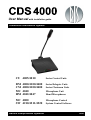
User Manual with installation guide
Conference Discussion System
CU 4005/4010
Series Central Units
DM
CM
MU
HM
Series Delegate Units
Series Chairman Units
Microphone Unit
Hand Microphones
4000/4100/4400
4000/4100/4400
4040
4042/4047
MC 4000
SW 4210/4211/4220
Danish Interpretation Systems
Microphone Control
System Control Software
DIS
CDS 4000
LIST OF CONTENTS
List of Contents
List of Contents ..................................................... 2
Document version.............................................. 4
Warning ................................................................. 5
Front panel controls .....................................14
Rear panel connectors ..................................15
Installation instructions................................. 16
Where to place .............................................16
Ventilators....................................................16
Removing 19"-brackets................................16
How to open the unit ....................................16
For all customers ............................................... 5
Important ......................................................... 5
Internal settings ............................................. 17
Caution ............................................................... 5
DM/CM4000 Delegate & Chairman units.... 17
DM4000 Series Delegate Units..................... 17
Important............................................................... 6
Changing the voltage settings.......................17
Safety .................................................................. 6
Auto Mode ...................................................17
Manual Mode ...............................................18
First-In-First-Out Mode................................18
Installation ......................................................... 6
CM4000 Series Chairman Units ................... 18
Cleaning.............................................................. 6
Repackaging....................................................... 6
Warranty............................................................ 6
Manual and Automatic Modes .....................18
First-In-First-Out Mode................................18
DM/CM4410/4420 Delegate & Chairman Units
.......................................................................... 19
DM 4400 Series Units................................... 19
Set-up ...........................................................19
Description of the system ..................................... 7
Features.............................................................. 7
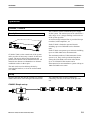
System components ........................................... 8
Modes of operation............................................ 9
Operation............................................................. 10
CU4005, CU4010 ............................................. 10
Description .................................................... 10
Set-up............................................................. 10
CU4005 Simple set-up ................................. 10
CU4010 set-up with external mixer............. 11
DM/CM 4100 Voice active units.................... 19
4100 Series set-up ......................................... 19
DM 4100 Series Delegate Units.................... 20
CM 4100 Chairman Units ............................. 21
CB 4100 Control box .................................... 21
Dynamic voice response (DVR) ................... 23
MU4040 Microphone Unit ............................. 24
Description .................................................... 24
HM4042/HM4047 Hand Microphones ......... 25
Description .................................................... 25
Controls......................................................... 25
Display function ............................................ 11
System enhancement .......................................... 26
Exit .............................................................. 12
Test.............................................................. 12
Status ........................................................... 13
Set-up .......................................................... 13
Display, slaves............................................. 14
MC4000 Microphone Control........................ 26
Description .................................................... 26
Location of controls ...................................... 27
Location and functions of controls................ 14
Manual no. 4479, Printed in Denmark, 02/03
Start-up.........................................................27
2
CDS 4000
Standard Operations mode .......................... 27
System Settings Operation mode................. 29
Test Operation mode ................................... 29
Program Operation mode ............................ 30
Error detection feature................................. 31
Setting up a large system............................... 32
SW4200/4210/4220 System Control Software33
Installation guide ................................................ 34
General installation rules ............................... 34
Standard portable units.................................. 34
Flush Mounted Units ..................................... 34
Ribbon Cables ............................................. 35
Control Link Cables ...................................... 36
MC4000 Microphone Controller................... 37
RS4232 Serial Communication Module........ 37
CU4005/CU4010 Central Units .................... 38
Voice Activated Microphones....................... 38
Accessories........................................................... 39
Microphone extension cables ........................ 39
Cable Conversion Accessories ...................... 39
Control link cables......................................... 39
Specifications....................................................... 40
Electrical .......................................................... 40
CU4005/CU4010 Central Unit ...................... 40
General ............................................................. 41
Power requirement......................................... 41
Power consumption ....................................... 41
Temperature to guarantee specified performance
....................................................................... 41
Storage temperature....................................... 41
Weight ........................................................... 41
Accessories supplied ..................................... 41
Dimensions ....................................................... 42
DM/CM4410 P Delegate/Chairman Unit ...... 42
DM/CM4420 P Delegate/Chairman Unit ...... 42
CU4005/CU4010 Central unit....................... 42
MC4000 Microphone Control ....................... 42
Pin assignments ............................................... 43
CU4005/CU4010 ........................................... 43
Manual no. 4479, Printed in Denmark, 02/03
LIST OF CONTENTS
Line in (XLR3 female) / Microphone output
(XLR3 male) ................................................43
Microphone Chain connector (D15 female).43
Control link connector (D9 female / D9 male)43
RS232 connector ..........................................44
RS422 connector ..........................................44
DM/CM4121 & MU4040 ............................. 45
Input (HD15S) .............................................45
Accessories (not supplied) .............................. 45
Appendix 1, External Control of the CU 4005 / CU
4010 ...................................................................... 46
General............................................................ 46
Data from the RS4232 Card ...................... 46
Startup message from RS4232 ...................... 46
Number of microphones connected .............. 46
Chairmen connected...................................... 46
Maximum number of delegates speaking...... 47
Maximum number of delegates in request .... 47
System mode ................................................. 47
Volume Control............................................. 47
Microphone is turned on ............................... 47
Microphone in Speak .................................... 47
Microphone is put in Request ....................... 47
Microphone in Request ................................. 48
Microphone is turned off .............................. 48
Delegate Off activate acknowledge message 48
Delegate Off deactivate acknowledge message48
Conversion Table download acknowledge
message ......................................................... 48
Test status message ....................................... 48
RS4232 card internal buffer overflow .......... 48
Serial Receive overflow ................................ 49
Data to the RS4232 Card................................ 50
System status request messages .................... 50
Microphone status request ............................ 50
Commands to control the microphone system50
Delegate Off activate message ...................... 50
Delegate Off deactivate message .................. 50
Conversion Table Download message .......... 50
DM / CM 4100 Series Voice Activated
microphone units ............................................ 51
3
CDS 4000
LIST OF CONTENTS
Document version
Printed:
02-06-2003
Version:
E
Name: CDS4000E.DOC
Copyright© 1999-2003 DIS, Danish Interpretation Systems A/S
No part of this publication may be reproduced or utilised in any form or by any means without permission in writing from the
publisher.
Manual no. 4479, Printed in Denmark, 02/03
4
CDS 4000
WARNING
Warning
Brown:
For all customers
The equipment has been tested and found to
comply with the limits of the CE test. These limits
are designed to provide reasonable protection
against harmful interference when the equipment is
operated in a commercial environment. The
equipment generates, uses, and can radiate radio
frequency energy and if not installed and used in
accordance with the user manual it may cause
harmful interference to radio communications.
You are cautioned that any changes or
modifications not expressly approved in this
manual could void your authority to operate this
equipment.
Live
The colours of the wires in the mains lead of this
apparatus may not correspond with the coloured
markings identifying the terminals in your plug, so
please proceed as follows:
The green-and-yellow wire must be connected to
the terminal in the plug marked with the letter E or
with the safety earth symbol or marked with greenand-yellow colour. The blue wire must be
connected to the terminal marked with the letter N
or marked with black colour. The brown wire must
be connected to the terminal marked with the letter
L or marked with red colour.
Caution
Important
The apparatus must be connected to earth.
The wires in the main power cord are coloured in
accordance with the following codes:
Do not disconnect any central unit unless the
main power has been disconnected.
Green-and-yellow:
Blue:
Earth
Neutral
Manual no. 4479, Printed in Denmark, 02/03
5
CDS 4000
IMPORTANT
Important
Safety
Cleaning
Check that the operating voltage of the unit is
identical with the voltage of your local power
supply. If a voltage conversion is required, consult
your DIS dealer or qualified personnel.
To keep the cabinet in its original condition,
periodically clean it with a soft cloth.
Should any liquid or solid object fall into the
cabinet, unplug the unit and have it checked by
qualified personnel before operating it further.
Unplug the unit from the wall outlet or set the Main
Power switch to OFF if it is not used for several
days.
To disconnect the cord, pull it out holding the plug.
Never pull the cord itself.
Installation
Allow adequate air circulation to prevent internal
heat built-up. Do not place the unit on a surface
(rugs, blankets, etc.) that may block the ventilation
holes.
Do not install units in a location near heat sources
such as radiators or air ducts, or in a place exposed
to direct sunlight, excessive dust or humidity,
mechanical vibration or shock.
To avoid moisture condensations do not install
units where the temperature may change rapidly.
Stubborn stains may be removed with a cloth
lightly dampened with a mild detergent solution.
Never use organic solvents such as thinners or
abrasive cleaners since these will damage the
cabinet.
Repackaging
Save the original shipping carton and packing
material. They will become handy if you ever have
to ship the unit. For maximum protection, repack
the unit as originally packed from the factory.
If not supplied with the equipment, a complete
transportation and storage box system is available
from DIS. We recommend you to use this system
for long term protection and care.
Warranty
The individual units in the CDS 4000 is minimum
covered by 12 months warranty against defects in
materials or workmanship.
Please further observe the installation guidance
provided in this manual.
Manual no. 4479, Printed in Denmark, 02/03
6
CDS 4000
DESCRIPTION OF THE SYSTEM
Description of the system
Features
The CDS 4000/4100 is an advanced microprocessor
controlled system using the latest technology to
make it possible to handle a large number of microphones.
Main features:
• Can handle up to 1000 Delegate units
• Can operate in Automatic, Manual, FIFO or
Voice Activated modes
• Can be controlled by RS232/422
• Portable/flush mounted units available
• Custom-made models available
Basically the CDS 4000 system can be a fully
automatic system with up to 100 microphones when
used with one CU4010 or up to 10 x 100 = 1000
Manual no. 4479, Printed in Denmark, 02/03
microphones when used with up to ten CU4010
Central Units.
The CDS 4100 is an extension to the CDS 4000
offering Voice Activated microphone units.
With the MC4000 Microphone Controller other
features are added to the system such as operator
panel, remote volume control, test function,
monitor function and other operation modes.
By installing an optional RS4232 module in the
CU4005/CU4010 it will be possible to monitor the
status and control the system from a personal
computer via RS232 or RS422.
Installation of the CDS 4000 system is extremely
easy since the microphone units hold the
connection cable themselves.
By using genuine DIS extension cables, installation
can never be made incorrectly.
7
CDS 4000
DESCRIPTION OF THE SYSTEM
System components
All units, which are part of the CDS 4000 system, are listed below.
Model
Description
CU4005
Central Unit.
Automatic and FIFO operation modes, 50 microphone units connected as maximum. Interconnection
of up to ten CU4005/CU4010 units for of up to 500/1000 microphones. Manual operation with
MC4000 and computer control with optional RS4232 module built-in.
CU4010
Same as CU4005, but with two chains each of up to 50 microphone units, max. 100 microphone
units.
RS4232
Personal Computer Interface with both RS422 and RS232 communication ports.
MC4000
Microphone Controller for CU4005/CU4010.
Automatic, FIFO and manual operation, full control of up to 1000 microphone units, remote volume
controls and monitor function.
SW4210
CDS 4000 Commander. Max. 100 microphone units for Windows ’95/NT
SW4211
CDS 4000 Commander. Max. 1000 microphone units for Windows ’95/NT
SW4220
Additional Software for the SW4210/11including Geographical Display for Windows
’95/NT.
DM/CM4410
Delegate/Chairman microphone with loudspeaker and fixed gooseneck mic. arm with built-in light
indicator.
DM/CM4420
Delegate/Chairman microphone with loudspeaker and XLR-socket for mic.
DM/CM4011
Delegate/Chairman microphone with fixed gooseneck mic. arm with built-in light indicator.
CB4100
Control Box to be used in conjunction with the 4100 series voice activated microphones. Delivered
with LS4100 P loudspeaker for adjustment.
LS4100
Loudspeaker Unit for adjustment of gain
DM/CM4120
Voice Activated/Manual Delegate/Chairman Unit with loudspeaker and XLR-socket for mic.
DM/CM4121
Voice Activated/Manual Delegate/Chairman Unit with XLR-socket for microphone.
MU4040
Delegate/Chairman Microphone Unit. Electronic box for invisible installation
GM4022
Gooseneck microphone with XLR-plug and built-in light indicator.
HM4042
Hand Microphone with On/Off switch with light indication and built-in light ring.
HM4047
Hand Microphone with On/Off switch with light indication.
LS4000
Loudspeaker Unit.
SU4000
Loudspeaker Unit with outlet for headphone.
Note: Most system units are available in both portable and flush mounted versions. The actual version is
recognised by a P (portable) or F (flush mount) after the model number.
Manual no. 4479, Printed in Denmark, 02/03
8
CDS 4000
DESCRIPTION OF THE SYSTEM
Modes of operation
The CDS 4000 system can be operated automatically and in FIFO mode when a CU4005 or
CU4010 is used alone.
Together with the MC4000 or controlled via the
optional RS4232 board, the CDS 4000 system can
also be operated manually.
In addition the CDS 4100 can be operated in voice
activated mode in combination with CB 4100.
In short, the operation modes are:
• Automatic
Delegates are allowed to switch their microphones on and off themselves by means of
the ON/OFF-button on the microphone units.
The red Speak light indicates that the
microphone is ON.
• FIFO (First In First Out)
The same as above, but when the limit of
allowed speakers is reached, the next delegate
pushing the ON/OFF-button on the microphone
unit will not go On, but will be placed in
Request. So will all the next.
They will all be placed in a request queue with
the first in the queue flashing with the green
Request light indicating that he is next to speak.
When one of the open (ON) microphone units is
Manual no. 4479, Printed in Denmark, 02/03
switched off, the next will automatically be
switched on. Usually this mode is used with
Max. Speakers set to 1.
• Manual
Delegates cannot turn their microphone on
directly, but only make a request to speak by
pushing the ON/OFF-button on the microphone
units. The microphone can then be turned on
from e.g. the MC4000 or a PC. The green Request light indicates that a "request to speak" has
been made, and the red Speak light that the
microphone has been turned on by e.g. the
MC4000 or a PC.
Delegates can still turn their microphone off
themselves in manual mode or they can cancel
their request to speak made.
• Voice Activated (DVR)
Each microphone switches on automatically
when spoken to and off again after a period of
silence. The sound level required to switch on a
second (third, fourth...) microphone changes
dynamically to prevent random microphones to
switch on because of background noise. This
unique DIS feature is named DVR, Dynamic
Voice Response.
9
CDS 4000
OPERATION
Operation
CU4005, CU4010
Description
The CU4005/CU4010 contains the power supply
for the system. The mains input can be selected to a
wide range of AC-voltages making world-wide use
of the system possible.
An electronically balanced line is provided for tape
recorders, buffer amplifiers, etc.
Each CU4005 is limited to operate 50 units
including up to ten CDS 4000 series chairman
units.
Each CU4010 can operate up to 100 units including
up to ten CDS 4000 series chairman units.
CU4005/CU4010 is the central unit of the system
and it provides all necessary controls for the basic
system. The unit is delivered in chromate and
painted steel cabinet with an aluminium front. All
materials are chosen to withstand severe climatic
conditions such as in the tropics.
The unit can be used as tabletop cabinet by
removing the brackets, or it can be rack mounted
(19"-2HE).
The maximum number of Chairman units for the
system is 10. They can be positioned anywhere
among the CDS 4000 series units in the chains.
Up to 10 CU4005/CU4010 units can be
interconnected to accommodate a system with up to
1000 CDS 4000 series units.
Set-up
Plugging the first unit into the CU4005 or CU4010
makes connections of the Delegate/Chairman units.
The CDS 4000 units are daisy-chained by
connecting each unit to the back of the previous
one.
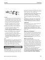
CU4005 Simple set-up
Manual no. 4479, Printed in Denmark, 02/03
10
CDS 4000
OPERATION
In this situation the level of the DM/CM4000 units
connected to the Delegate Microphones connector
is adjusted with the Microphone Volume control,
and the level of the wireless microphone connected
to the Input connector is adjusted with the Input
Volume control.
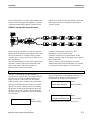
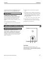
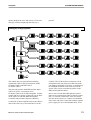
CU4010 set-up with external mixer
In this set-up an external PA system is connected
along with some auxiliary microphones. Since only
one input connector is available on the CU4005
/CU4010 unit, it will be necessary to make use of
an external mixer.
CU4005/CU4010 input respectively. The
Microphone Volume control of the
CU4005/CU4010 must be muted totally in this
situation, since the mix of all signals is now done at
the external mixer.
The extra microphones as well as the output signal
from the CU4005/CU4010 are connected to the
inputs of the mixer. The mixer outputs are
connected to the PA system and the
A set up with an external equaliser for sound
equalisation of the built-in loudspeakers is possible
by connection of the equaliser in a similar way.
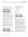
Display function
The unit is switched on with the POWER (1)
switch. (Please refers to the “Front panel controls”
section). If more units are linked together for a
larger system, it is advised to have an external
common mains power switch for all central units.
After power ON the units are ready for operation
after 20-30 seconds. The time is used for finding
the number of central and microphone units, and
setting up the system. It takes less time next time
the same set-up is switched on. The LCD-display
(6) will show:
CU Initializing 1.0
Menu:
INITIALIZING
Manual no. 4479, Printed in Denmark, 02/03
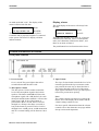
If more central units or microphone controllers are
linked together, and one or more units are not
switched on, the display can look like this:
CU Initializing 1.0
Menu:
Unit:4 NOT Powered
INITIALIZING
CU Initializing 1.0
Menu:
Previous NOT Powered
INITIALIZING
or
1.0 indicates that the software is version 1.0.
11
CDS 4000
OPERATION
Note:
When the CU4005/CU4010 has the RS4232
module built-in, this unit will count as two units.
buttons < or > the markers < > can be moved
respectively left and right.
The four choices in the Main menu are:
After successful set-up time the LCD-display of the
master CU will look like this:
Total Mic:125
Menu:
Vol: Inp=off Mic=-20
MASTER
Total Mic:125 indicates that there are 125
microphone units including chairman units
connected in the system. Vol: Inp=off indicates
input volume is totally muted, and Mic=-20
indicates that the audio level of the microphone
sound is attenuated with 20 dB.
The central unit, which have no other central units
connected to the D9-connector PREVIOUS, will be
MASTER or CU 0, and the first unit connected to
the D9-connector NEXT will be SLAVE 1 or CU 1
and so on up to SLAVE 9 or CU 9 (if present).
The system will always function with the same
settings of volume, mode, max. speakers and max.
requests as those selected 10 seconds before the
system was switched off.
The settings are stored in the master CU. If the
order of the CU's is changed and a new one
becomes master, then the settings of this unit (when
it last was master) will be used.
All settings including volume settings will be
written into EEPROM (Electrical Erasable
Programmable Read Only Memory) after a period
of no pressing of push buttons in 10 seconds. This
ensures that the system has the same settings after a
power down.
If Enter is pressed once, the display will show this:
<EXIT>
STATUS
TEST
SETUP
Menu:
MAIN
The markers < > shows the function which can be
selected now with the ENTER button. By using the
Manual no. 4479, Printed in Denmark, 02/03
•
•
•
•
Exit
Test
Status
Setup
Exit
Returns to the Master menu.
Test
The following menu will appear:
<EXIT> TEST STEP
Menu:
CU0 Chain1 Mic1 Req
TEST
Here we can select between TEST, STEP and EXIT:
Test
The test function enables you to confirm that the
control units have control of all the microphone
units connected to the system.
To activate the function, place the < > markers
around TEST and push the ENTER button. An
automatic test of all the microphones is started
beginning by setting microphone #1 in chain 1 on
CU 0 in Request for 0,375 second. The text in the
lower line on the display will look like shown
above. Then the same microphone unit will be
switched on for 0,75 second and the text Req
changes to Mic. Then the next microphone unit will
be set in request, switched on and so on.
After completion of testing all the microphones, the
test starts from the beginning again. To stop testing,
press ENTER again. If a faulty microphone unit (or
perhaps a bad connection) is detected, the test will
stop at that point.
To locate a possible fault, first check all
connections in the chain of microphone units. Then
activate the test function again. If a fault is still
indicated, you need to remove microphone units
12
CDS 4000
OPERATION
one by one in between new test cycles, until no
fault is reported. In this way it is possible to locate
a bad unit in the chain.
Note:
All microphones must be switched off before the
test functions are activated. Otherwise the test
functions cannot be started. If a button is pressed
down on a microphone unit, while one of the tests
is active; the test will stop, as this is recorded as an
error.
Step
After the function is selected with ENTER, each
microphone can be switched on one at a time by
pushing the > button starting with the first
microphone and stepping one up for every push.
Pushing < will step backwards. The sign * will be
shown in the display right to STEP. With this
function you can check selected microphones for
the audio quality for longer periods. The lower line
of the display shows the same as above except for
Req.
Exit
Pushing ENTER will always bring you back to
display the previous menu ending up with the
master display.
Status
The display will look like this, when STATUS is
selected:
Chain1:25 Chain2:0
Menu:
Chair:1/2 Slaves:3
STATUS
Note:
CU4005 has no possibility for use of chain 2.
This shows on the upper half how many
microphone units are connected to the master on
chain 1 (and chain 2). The line below it shows how
many chairman microphone units are connected to
the master / how many in the whole system. Also
the number of connected slaves is shown.
Manual no. 4479, Printed in Denmark, 02/03
If a fatal fault is present in a chain, and the central
unit is incapable of recording the number of
connected units, then the STATUS display will
look like this:
Chain1:?? Chain2:25
Menu:
Chair:0/2 Slaves:3
STATUS
The two ?? replacing the number of units indicates
an error, in this case on chain 1. Please observe that
51 or more microphones connected in one chain
will result in an error as well.
Set-up
The SETUP menu looks like this:
EXIT <MODE> auto
Menu:
MAXSP 3 MAXRQ 50
SETUP
When MODE is selected by pressing ENTER as
above, a cursor will appear at auto. The < and >
buttons can now be used to scroll between the
different function modes. When the CU's stand
alone the mode auto or fifo can be selected by
pushing ENTER.
At MAXSP (Maximum number of speakers)
selected with ENTER, the maximum number of
delegate microphones allowed to be ON can be
selected. Use > and < to step the number up and
down. It can be selected between 1 and 6. All
chairman microphone units can always switch on.
This setting has effect on all modes of operation.
If you wish to limit the Request To Speak queue,
this can be done at MAXRQ as above. The
maximum number of requests can be set between 0
and 999. This setting influences the manual and fifo
modes. Note: If e.g. 10 mics. are already in request,
setting the max.request to 4 will not delete any of
these requests, but no further mics. can be put in
request before the queue is less than four.
When an MC4000 Microphone Controller or a
personal computer is connected to the system, it is
also possible to select the mode manual and even
customised modes. Is this the case, these selections
13
CDS 4000
OPERATION
are made at the MC or PC. The display of the
master will then look like this:
Total:125
PC/MC
Vol: Inp=off Mic=-20
Menu:
MASTER
This indicates that an MC4000 Microphone
Controller and/or personal computer is connected
to the system. The STATUS display will then
indicate manual.
Display, slaves
The LCD-display of the slaves will always look
like this:
Slave:1 Chairmen:1
Menu:
Chain1:24 Chain2:0
SLAVE
This indicates, that this CU is slave #1, it has one
chairman unit connected, it have 24 microphone
units (incl. chairman) connected to chain 1, and
there are no units on chain 2.
The push buttons have no function on the slaves.
Location and functions of controls
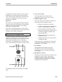
Front panel controls
1. Power On/Off
Power switch. The green light in the rocker
switch indicates that the unit is ON.
2. Microphone Volume
The Microphone Volume buttons control the
level of the microphone signal in the built-in
speakers. The button marked t will lower the
microphone signal with 1 dB (decibel) for each
short push and the button marked s will raise the
input signal 1 dB. If one of the buttons is
pressed more than 1 second, the level will be
changed in 1 dB steps four times a second, as
long as the button is pressed. The level can be
changed from +20 dB gain to -42 dB attenuation
and off. A normal setting will be between -20 to
+6.
Manual no. 4479, Printed in Denmark, 02/03
3. Input Volume
The Input Volume button controls the level of an
external signal from the Input connector at the
rear panel in the same way as described above.
The setting depends on the level of the actual
input signal. It should be set to off, if the input is
not used to prevent noise pick up.
Note:
The volume controls can always be used on the
master, also if the display shows menus and the
volume settings cannot be seen.
For more specific information about the volume
controls refer to the schematic next page and the
Set-up section under Operation.
14
CDS 4000
4. Enter
This button is used to enter the menus and select
a chosen value.
The markers < > around exit show the function
which can now be selected with the ENTER
button. If it is pushed again now, we will get
back to the master (default) display shown
above.
OPERATION
5. < and >
These buttons are used to step the markers < >
left and right respectively for each push.
6. LCD Display
Indicates the setting of the system.
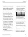
Rear panel connectors
1. Mains Connector
Connection for mains power. The unit can
accept the following voltages:
110V/130V/150V/220V/240V/260V depending
on the setting of the internal switch.
Before connecting the CU4005/CU4010 Central
Unit to the mains, please check that the voltage
shown on the label close to mains socket is in
conformity with the voltage with which it is to
be used.
2. Microphone Chain
Connector for the first DM/CM4000 Unit
connected in the chain. A maximum of 50
microphone units can be connected at a time.
3. Expansion of more CU4005/CU4010s
controller is also connected here. A maximum of
ten CU4005/CU4010 units and two MC4000s
can be interconnected.
The central unit with none or only the MC4000
connected to the PREVIOUS connector
becomes the master unit.
4. Microphone Output
The output delivers the signal from the
microphones independently of the Microphone
Volume setting on the front panel. Also, the
output is totally independent of the input signal.
The output signal is typically used for tape
recording or an external PA-system and is
nominal 0 dBm line-signal and –40dBm
microphone level respectively.
More central units are connected to these
connectors for systems with more than 50/100
microphone units. The MC4000 Microphone
Manual no. 4479, Printed in Denmark, 02/03
15
CDS 4000
OPERATION
has become overheated, turn Off the power, remove
things that prevent proper ventilation and wait until
it has cooled down. Then turn On again.
CAUTION: Do not remove rubber pads in bottom,
as they are needed for proper ventilation.
5. Input
The input signal is mixed with the internal microphone signal by means of the Input Volume
and Microphone Volume controls on the front
panel. The resulting signal is then routed to the
internal speakers in the microphone units.
The input is typically used for a wireless microphone or playback from a tape recorder.
6. RS422 PC Serial Data Control (Optional)
Connector for personal computer or other
equipment with RS422 serial data
communication. The equipment must have
software compatible with the CDS 4000 system.
7. RS232 PC Serial Data Control (Optional)
Connector for personal computer or other
equipment with RS232 serial data communication. The equipment must have software
compatible with the CDS 4000 system. Both 6
and 7 can be used at the same time e.g. two
computers.
Note:
Please note that there is no connection between the
input and output of the CU4005/CU4010 unit, i.e. if
you make a recording from the output of the unit, it
will only be the signal from the delegate units you
record. An input signal to the Line In on the
CU4005/CU4010 will not appear at the output.
Installation instructions
Where to place
The CU4005/CU4010 unit can be placed on a table.
Do not place anything on the unit as the unit will
overheat and stop functioning correctly. If the unit
Manual no. 4479, Printed in Denmark, 02/03
The CU4005/CU4010 can also be installed in a
19"-rack using the holes in the brackets on each
side.
CAUTION: It is important to have at least one
blank 1HE-high front plate over and under the
CU4005/CU4010 to keep sufficient ventilation.
Ventilators
It may be necessary to have ventilators in the rack
over or under the unit(s) if e.g. two
CU4005/CU4010 units are placed in the same rack.
The ventilators are only needed to give a small
amount of airflow up through the units. A blank
1HE-high front plate should also be placed between
the two units.
Removing 19"-brackets
If the unit is placed on a table and the brackets are
not used, then these can easily be removed. Screw
out the two screws holding each bracket; remove
the brackets and screw in the screws again. Be
careful, do one side at a time as these screws also
hold the cabinet together.
How to open the unit
Take out mains plug. Place the unit on a table.
Remove the two upper screws in each side. Remove
upper screw in the top middle of back plate. Now
lift approx. 1.5 cm up the back of the top lid, so the
inside bracket at the middle back of the lid is free
of the back plate. Then slide the lid backward away
from the front plate until the front bracket releases
(approx. 2 cm). Remove top lid.
CAUTION: Never open unit with power cord
connected. Do not operate unit with cover
removed to avoid a potentially dangerous shock. If
any trouble arises that cannot be rectified by
external checking of the CU4005/CU4010 and
16
CDS 4000
connected units, then you should approach your
dealer or order service by qualified personnel.
OPERATION
2. Open the unit (see section “How to open the
unit).
3. The voltage selector is placed in the right side of
Internal settings
the unit close to the front. Turn the selector with a
coin and Select the voltage equal to or within +/10% to one of the following voltages shown on
the rotating selector:
Changing the voltage settings
Before connecting the CU4005/CU4010 Central
Unit to the mains, please check that the voltage
shown on the label close to mains socket is in
conformity with the voltage with which it is to be
used.
110V - 130V - 150V - 220V - 240V - 260V
4. The primary fuses are located just below the
selector; the same fuses are used for all settings.
If any incongruity, do the following:
5. Replace top cover and screws.
1. Switch off the unit and remove the mains power
.
cable.
DM/CM4000 Delegate & Chairman units
DM4000 Series Delegate Units
The 4000 series microphones work in three
different modes - automatic (Auto), first-in-first-out
(fifo) or manual - according to the settings of the
system. If the CU4005/CU4010 is used without
MC4000 or personal computer, the operation mode
is automatic or first-in-first-out (refer to section
Modes of Operation).
Auto Mode
When pressing the ON/OFF button (1) the
microphone turns on. This is indicated by red light
in the speak lamp (2). Pressing the button again will
turn the microphone off.
Manual no. 4479, Printed in Denmark, 02/03
17
CDS 4000
OPERATION
Manual Mode
CM4000 Series Chairman Units
Pressing the ON/OFF button will place the
microphone in the request queue of the MC4000.
This is confirmed by green light in the request lamp
(3). It is possible to cancel the request by pressing
the button again.
Pressing the ON/OFF button (1) will always turn
the microphone on or off depending on the current
state. Red light in the speak lamp (2) indicates that
the microphone is on.
The microphone can only be switched on from the
MC4000 or personal computer, and this will be
indicated by red light in the speak lamp (2). At this
point the delegate can switch off the microphone by
pressing the button (1).
First-In-First-Out Mode
The microphone unit functions in the same way as
in automatic mode as long as the number of turned
on microphone units is under or equal to the
selected maximum speakers. When the max.
number is reached, the next delegate pressing the
ON/OFF button will be put in the top of the request
queue. This is indicated by the green request lamp
(3) flashing slowly. More delegates will be put in
the queue when they press their buttons, until the
maximum of requests is reached. Their green lamps
will light up steadily. When one of the turned on
microphone units is switched off, the first
microphone in the queue is automatically switched
on, and the next in the queue will flash with the
green lamp. This mode will normally be used with
only 1 as maximum speakers.
Note:
When MC4000 or a personal computer is not used,
the request queue can only be deleted by pressing
the ON/OFF button on all microphone units in
request or by switching off the system.
Manual no. 4479, Printed in Denmark, 02/03
Manual and Automatic Modes
Pressing the DELEGATE OFF button (4) will turn
off all delegate microphones. The delegate off lamp
(3) will turn on shortly as confirmation.
First-In-First-Out Mode
Pressing the DELEGATE OFF button (4) will turn
off all delegate microphones as long as the button is
pressed. When the button is released, the delegate
microphones will turn on again. This is used to
interrupt a discussion between delegates for a short
message from the chairman.
18
CDS 4000
OPERATION
DM/CM4410/4420 Delegate & Chairman Units
DM 4400 Series Units
The 4400 series microphone operates exactly like
the 4000 series microphone described in the
previous section. All delegate and chairman
functions described are the same.
Set-up
Whereas the daisy chain cable connector on the
4000 & the 4100 series units are locked to the
previous unit by two finger screws, the 4400 series
units have a built in easy snap locking mechanism
in the bottom of the unit.
Strain relief is provided by two parallel cable
grooves provided with taps to secure the cable. The
connection is thus invisible and the cables will run
close together out of the rear of the unit.
For more permanent set up the cables can be lifted
out of the groove and down through a hole cut in
the table right underneath the unit.
DM/CM 4100 Voice active units
4100 Series set-up
A CDS 4000 system may be upgraded to work with
the 4100 series DVR microphone units by use of
the CB 4100 control box.
The 4100 series of voice activated microphones can
be used in a stand-alone set-up or in combination
with the 4000 series of auto/man. microphones.
The CB 4100 Control Box should always be
present in a set-up when voice activated
Manual no. 4479, Printed in Denmark, 02/03
19
CDS 4000
microphones is required. The box is placed at the
beginning of the chain right before the required
voice activated units. Without the control box the
4100 series microphones will work as normal
auto/man. microphones.
Important
The 4100 series of microphones and the CB 4100
cannot be used with older models of the MS 4000
and the CU 4000. Any attempt to do so might
damage the microphone units.
OPERATION
5. Voice Active Lamp
This lamp lights yellow whenever the
microphone works in Voice Active mode.
6. XLR-microphone socket
This socket allows for connection of the most
commonly used microphones such as:
• Dynamic microphones (200 ohm).
• Condenser microphones (200 ohm) that
accept +9V phantom power supply.
If you have any doubts about the version of your
MS or CU, you should check the serial number and
call DIS A/S for further information.
• Electret condenser microphones with
built-in FET and positive supply such as
the DIS microphones GM40xx, SM
4025 and SM 4026.
DM 4100 Series Delegate Units
• Balanced low level line signals (max
26 dBm/600 ohm).
As mentioned earlier the 4100 series microphones
work in two different modes: the original "series
4000 mode" and in the voice activated mode. In the
original mode the DM 4100 works exactly as
described for the DM4000 above. The function in
voice activated mode is described in a later section.
-
• Unbalanced low level line signals (max
-20 dBm/600 ohm).
After connecting a microphone, the level must
be adjusted as described in section “CB 4100
Control Box - Level adjust”.
7. Level Adjust
Through this hole the input level on the
microphone socket (6) can be adjusted as
described in section “CB 4100 Control Box Level adjust”.
8. Headphone Connector
This mini-jack socket allows for connection of a
headphone or tape recorder. The output is
parallel to the built-in loudspeaker with the
exception that this signal is not cut off when
switching on the microphone.
The additional connectors and lamps on the DM
4100:
Manual no. 4479, Printed in Denmark, 02/03
20
CDS 4000
OPERATION
CM 4100 Chairman Units
The function of this unit is similar to the
description of the CM4000 regarding the normal
auto/man. mode and the DM 4100 regarding the
4100 series features.
The three buttons on the control box selects one of
the operation modes.
1. Man./Auto. Mode
Please refer to the section “CB 4100 Control Box”
for information on the voice activated mode and
level adjustment of the microphone input.
CB 4100 Control box
The control box is placed in the chain somewhere
before the DM/CM 4100 Units; normally it will be
placed next to the central unit. The box controls the
three modes of operation of the DM/CM 4100
units: Man./Auto (as standard units), Voice
Activated and Level Adjust. If both chains on the
CU4010 are used with 4100 units in the VOICE
ACTIVATED mode, then two CB 4100s must be
connected.
If the control box is missing, all microphones regardless of series, will work in normal auto/man.
mode.
Manual no. 4479, Printed in Denmark, 02/03
The selection of this mode is indicated by green
light in the lamp above the button. The control
box will remember this mode - also after a
power off. Both 4000 and 4100 units will
function as standard units with on/off control by
the delegates or by the operator.
2. Voice Activated Mode
The selection of this mode is indicated by
yellow light in the lamp above the button. The
yellow Voice Active lamps on all the DM/CM
4100 connected after the CB 4100 will also light
up after a few seconds thus indicating the
current mode to the delegates.
The control box will remember this mode - also
after a power off. The DM/CM4000 series units
will function as standard, and the DM/CM 4100
series units will function as voice controlled.
If the MC4000 is used, it is still possible for the
operator to switch DM/CM 4100 series units on
(and off), but the push button on the
microphones has no function. If a unit is
21
CDS 4000
OPERATION
switched on by voice, it is not possible to force
it off remotely.
If CU4005/CU4010 is used as central unit w/o
MC4000, you need to switch off any units being
on, before selecting the mode Voice Activated.
Otherwise they will stay on and cannot be
switched off at the microphone unit.
3. Level Adjust
of the microphone unit. Pink noise is then
produced from the LS4100.
•
Place the loudspeaker in front of the
microphone arm in such a way that the
microphone touches the loudspeaker in the
middle of the grill in a 90° angel.
•
The level is then displayed with the two
lamps on the front plate of the microphone:
As the DM/CM 4100 series units are designed
for use with a variety of microphones, the
microphone-input level must be adjusted for
obtaining the same gain for all microphones.
The control box is designed with a Level Adjust
mode for making this adjustment as easy as
possible.
The selection of this mode is indicated by red
light in the lamp above the button. This mode
will not be remembered after a power down - the
system will start up in MAN./AUTO. mode.
When the mode is selected, the CB 4100 will
generate pink noise and route this - via the
volume control of the CU4005/CU4010 - to the
built-in loudspeakers and the jack connectors for
headphones in the 4100 units. The loudspeakers
of all standard 4000 units will produce the pink
noise continuously, while all 4120 units will
turn off their loudspeakers after a few seconds.
The pink noise is used as a reference for the
level adjustment of the microphones. The
volume should be set at a fairly high level for
precise adjustment of the gain of each
microphone: at app. +5 to +10. The level is not
critical but should be loud enough to suppress
any noise from the surroundings.
At this point the gain of each unit can be
adjusted with the supplied adjusting key (or a
small screwdriver) in the following way:
DM/CM4121 units
•
Connect the LS4100 Loudspeaker to the
headphone jack-connector in the front plate
Manual no. 4479, Printed in Denmark, 02/03
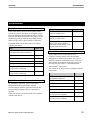
Level
Green lamp
Red lamp
Too low
ON
OFF
OK
ON
ON
Too high
OFF
ON
• The gain is adjusted through the hole in the
front plate above the XLR-connector (7).
Gain is increased by turning clockwise and
decreased by turning anticlockwise.
• There are ten full turns from low to high
gain, and the OK-window is only +/-1dB.
DM/CM 4120 units
• Use an extension cable (straight XLR-XLR)
between the microphone arm and the
DM/CM 4120s and hold the microphone so it
touches the built-in loudspeaker in the
middle of the grill in a 90° angel.
• Push the ON/OFF button on the unit. This
turns the built-in loudspeaker (and the noise)
on.
• Adjust the level as described above.
• Push the ON/OFF button to turn the
loudspeaker (and noise) off.
Note
The same procedure as described for the
DM/CM4121 units can also be used with the
DM/CM 4120 units. Avoid during the
adjustment to push the ON/OFF button on the
22
CDS 4000
microphone unit, as this turns the built-in
loudspeaker ON and gives a faulty noise level to
the mic.
OPERATION
4. Headphone Connector
This mini-jack socket allows for connection of a
headphone or the LS4100 Loudspeaker.
After this adjustment the output level of the
microphone units is the same as that of the
standard DM/CM4000 units.
Dynamic voice response (DVR)
The principles in the Dynamic Voice Response
system - also refereed to as Voice Activated system
- is described in this section.
After switching on main power and selecting Voice
Activated mode on the CB 4100, no microphone is
switched on, unless the background noise is louder
than the threshold level i.e. the noise level that
determines when the first microphone is switched
on (or the last one is switched off).
The microphone in front of the first delegate to
speak will switch on easily. The next delegate will
have to speak a bit louder than the loudspeaker
level of the first delegate speaking, in order to make
her/his microphone switch on.
The next delegates to speak needs also to speak
louder than the loudspeaker level to switch their
microphones on. This system prevents many
microphones to switch on at the same time; only the
microphones receiving the highest sound level
(compared to the current loudspeaker level) will
switch on.
When a delegate has finished speaking, her/his
microphone will switch off after a short delay,
assuming that some other delegate is speaking or
Manual no. 4479, Printed in Denmark, 02/03
that the background noise of the room is lower than
the threshold level.
Since the loudspeaker level is used as a reference
for the microphones to switch on and off (except
the first one), the sensitivity of the system is
adjusted by setting the loudspeaker level. This
means that a low level in the loudspeakers makes
the microphones switch on very easily, and raising
the loudspeaker-level makes it more difficult to
switch on the next microphone. If you are using a
system with no built-in loudspeakers, you should be
careful not to raise the output level too high, since
this will make it too difficult for the microphones to
switch on.
If the background noise level of the room is higher
than the threshold level, then at least one
microphone will stay on all the time, even if
nobody is speaking in it. In rooms with special
acoustics like churches, halls, etc. it is possible to
place a single microphone unit somewhere in the
room - away from the delegates -and force it to be
switched on all the time. This unit will then pick up
all ambient noise and make this the reference for all
other microphones to switch on and off.
23
CDS 4000
OPERATION
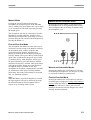
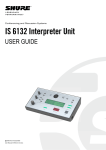
MU4040 Microphone Unit
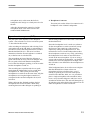
The MU4040 is set-up similar to the other
DM/CM4000 Series Units. The MU4040 operates
in the same modes as described for the
DM/CM4000 Series Units.
The MU4040 is provided with a fixed cable for
daisy chain connection to the back of the previous
unit, a connector for connection for the next
MU4040 unit and a HD 15S connector. The HD
15S is used for direct remote connection of:
Microphone (e.g. HM4042, GM40xx, GM44xx in
external outlet), microphone control buttons, LED
indicators and loudspeaker.
The MU4040 may also be used to switch on and off
a loudspeaker in a loudspeaker system with
separate amplification (e.g. a 100V system) via an
external relay.
Description
The MU4040 Microphone Unit is an electronic box
designed for hidden installation, e.g. in an armrest,
under a table or in a floor box.
Manual no. 4479, Printed in Denmark, 02/03
The MU4040 is designed for fixed mounting by
four screws.
24
CDS 4000
OPERATION
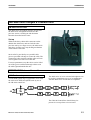
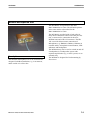
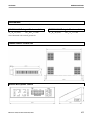
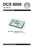
HM4042/HM4047 Hand Microphones
3.
2. 1.
HM4047 shown with cable
HM4042 shown without cable
Description
Controls
The HM4042/HM4047 Hand Microphone is
designed for use with the DM/CM 4121P Series
Units and the MU4040 unit. The microphone is
equipped with ON/OFF button as well as an
indicator. With an extension cable the microphone
can be connected to the DM/CM 4121P to either
the XLR connector (7) on the top or the HD15S
connector behind.
1. If the HM4042/HM4047 Hand Microphone is
connected to the HD15S connector, the function
of this button is the same as the ON/OFF button
on the Delegate/Chairman unit. If connected to
the XLR plug, the button has no function.
If connected to the XLR connector, the ON/OFF
button as well as indicator is not functioning.
Further the HM4042/HM4047 can be connected to
the HD 15S connector on the MU4040 unit.
Manual no. 4479, Printed in Denmark, 02/03
2. This indicator lights red when the microphone is
ON and green when in request, but only if the
HM4042/HM4047 is connected to the HD15S
connector. The indicator has no function if the
XLR plug is used.
3. This ring indicator lights red when the
microphone is ON, both when connected to the
XLR plug or to the HD 15S connector. The
HM4047 has no light ring.
25
CDS 4000
SYSTEM ENHANCEMENT
System enhancement
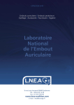
MC4000 Microphone Control
Description
MC4000 features:
• TEN KEY PAD CONTROL WITH DISPLAY
of any microphone unit switched to any
operating status.
• SINGLE BUTTON CONTROL of microphone
units displayed in Speak, Request, Preselect or
Last Speaker mode.
The MC4000 Microphone Control is a compact
desktop switchboard designed for the CDS 4000
system. It is used as an operating switchboard to
control the connected Delegate/Chairman units.
In manual, fifo and automatic mode, all
microphones can be controlled individually by the
MC4000. In voice activated mode only
DM/CM4000 series units can be controlled from
the MC4000.
For automatic, fifo and manual operation the
MC4000 provides auto updating of the Speaker’s
display and in manual mode the Request display as
well.
Manual no. 4479, Printed in Denmark, 02/03
• MODE DISPLAYS. Displays of the operating
modes AUTO, FIFO MAN or CUSTOM plus
TEST and PROGRAM modes. Display of total
number in Request, Display of Input & Mic.
Volume or Max. Req. & Max. Spk. settings.
• HEADPHONE OUTPUTS. Three sockets
available. One for 1/4 inch. jack plug and two
for 3.5 mm jack plug.
• TWO COLUMN DISPLAYS for display of
microphone number, microphone status
ON/OFF of Preselect and Chairman status.
• VOLUME CONTROLS for conference unit’s
loudspeaker level and headphone output level
with display of level settings.
• COMPACT DESIGN. Two MC4000 units can
be connected to a system. The MC4000 is
connected anywhere in the control link.
26
CDS 4000
SYSTEM ENHANCEMENT
Location of controls
Start-up
Standard Operations mode
The MC4000 Microphone Control unit is powered
from the CU4005/CU4010 Central Unit via the
Control Link Bus, and the MC4000 unit will power
on, when one or more of the CU4005/CU4010 units
are powered.
Upon completion of the initialization sequence the
MC4000 enters Standard Operations mode.
On Power Up the MC4000 displays a start-up
message "MC INIT v1.0" in displays D1, D2 and
D3, which tells the operator that the unit has
entered the initialising sequence in which the CDS
4000 units automatically configure the system and
establish the needed logical connections between
units. The software version of the MC4000 is also
displayed in the start-up message - v1.0 tells the
operator that this MC4000 is running the software
version 1.0.
D1 displays the Master CU mode, which may be
one of the following AUTO (Automatic mode),
FIFO (FIFO mode) or MAN (Manual mode). For an
explanation of these modes please refer to the
section “Modes of Operation” of this manual.
D2 displays the current number entered via the
numerical keypad, but following initialization D2
will display the total number of microphones
present in the system. This information confirms to
the operator that all microphones are connected in
the system. The display will be cleared when any
button on the MC4000 panel is pressed.
D3 displays the current setting of the Input Volume
on the Master CU (In dB). This volume may be
Manual no. 4479, Printed in Denmark, 02/03
27
CDS 4000
changed using the B2 buttons respectively to
decrease and increase the Volume in steps of 1 dB.
D4 displays the current setting of the Microphone
Volume on the Master CU.
This volume may be changed using the B3 buttons
respectively to decrease and increase the Volume in
steps of 1 dB.
SYSTEM ENHANCEMENT
request queue will not be visible. The preselected
microphones are distinguished from microphones in
the request queue by the letter 'P' preceding the
microphone number (e.g. "P 15"). The buttons BR
next to each display are used as short cuts to switch
these microphones ON. A microphone switched on
from the request queue will be removed from the
request queue, whereas a preselected microphone
switched on will remain in the preselected list.
The Headset Volume may be changed using the B4
buttons respectively to decrease and increase the
Volume in steps of 1 dB. The current volume
setting of this volume is not displayed on the
MC4000.
The numerical keypad ('0'-'9') is used to enter the
current microphone number displayed in D2.
The 6 DS displays shows the microphone numbers
of up to 6 current or previous speakers. The current
speakers are listed in the top positions with the
LED’s LS lit next to the microphone number. If
more than 6 microphones are switched on, only 6 of
these are displayed - the delegate microphones are
always displayed (no more than 6 delegate
microphones can be switched on at a time) and as
many chairmen microphones as possible are
displayed. Chairmen microphones are distinguished
from delegate microphones by the letter 'C'
preceding the microphone number (e.g. "C 21"). If
4 microphones or fewer are in speak, the DS
displays are also used to display previous speakers.
To distinguish previous speakers from currently
active speakers a display is blanked between the
bottom of the speaker list and the top of the
previous speaker’s list, and furthermore the LED’s
LS next to the previous speakers are NOT lit. The
buttons BS next to each display are used as short
cuts to switch these microphones ON or OFF. If a
microphone is currently switched on the BS button
next to the microphone number will turn the
microphone off and vice versa.
The 'R' key is used to put the current microphone
displayed in D2 in request or to remove the
microphone from the request queue if the
microphone is already present in the queue. If the
current microphone number is 0, pressing the 'R'
key will cause the MC4000 to display the total
number of microphones in the request queue in
displays D1 and D2 as long as the 'R' key is
depressed (e.g. "#Req 25").
The 6 RS displays show the top of the Request list
and/or Preselected microphones. The microphones
in the top of the request queue are listed in the top
display positions, and the preselected microphones
are listed in the bottom display positions. If 6
microphones are preselected, preselected
microphones will occupy all the displays and the
Manual no. 4479, Printed in Denmark, 02/03
The 'P' key is used to put the current microphone
displayed in D2 in preselect, or to remove the
current microphone from the preselect list if the
microphone is already on the list. If the current
microphone number is 0, pressing the 'P' key will
cause the MC4000 to display the total number of
microphones present in the system in displays D1
and D2 as long as the 'P' key is depressed (e.g.
"#Mic 332").
The 'S' key is used to put the current microphone
displayed in D2 in speak or to remove the current
microphone from the speaker’s list if the
microphone is already in speak.
The 'C' key is used to clear the current microphone
number displayed in D2. The 'C' key is also used in
conjunction with the 'P', 'R' and 'S' keys to further
enhance keypad operation. If the 'C' key is held
depressed, pressing the 'P' key will clear the
preselect list. Pressing the 'R' key will clear the
request queue, and pressing the 'S' key will switch
off delegate microphones currently in speak
(chairmen microphones will not be affected).
28
CDS 4000
Pressing the SET MODE (B1) button will change
the MC4000 mode of operation from normal mode
to system settings mode.
System Settings Operation mode
This mode of operation is used to monitor/change
the system settings for the microphone system, and
to enter the two special purpose modes Test
Operation mode and Program operation mode.
From the system setting mode it is not possible to
change the volume settings (Input, Microphone or
Headset) as the buttons/displays used for
controlling the volume settings in normal operation
mode are transferred in this mode to provide
additional functionality. It is still possible to fully
operate the microphones (switch ON/OFF, monitor
request list, etc.)
A LED bar next to the D3 display will light up with
the text MAXR indicating that the D3 display is
now used to display the maximum number of
delegate microphones allowed in the request queue
(e.g. "R 50"). This system setting can be changed
from the B2 buttons (respectively decrement by one
and incremented by one), but the new setting will
not be effective before the MC4000 mode of
operation is changed back to normal operation
mode.
A LED bar next to the D4 display will light up with
the text MAXS indicating that the D4 display is
now used to display the maximum number of
delegate microphones allowed to speak
simultaneously (e.g. "SPK3"). This system setting
can be changed from the B3 buttons (respectively
decrement by one and incremented by one), but the
new setting will not be effective before the
MC4000 mode of operation is changed back to
normal operation mode.
Next to the B4 buttons a LED bar will light up with
the text MODE indicating that these buttons are
now used for changing the mode of the microphone
system or MC4000 microphone controller as
indicated in the D1 display. Pressing one of the
buttons, the selection is switched between AUTO,
FIFO, MAN, TEST and PROG. AUTO, FIFO and
Manual no. 4479, Printed in Denmark, 02/03
SYSTEM ENHANCEMENT
MAN indicate the mode of the CU4005/CU4010 as
described in the CU4005/CU4010 section of this
manual, whereas TEST and PROG indicate modes
of operation applying solely to the MC4000
microphone controller. If the mode displayed in the
D1 display is changed, the new setting will only be
effective after the SET MODE button is pressed.
The SET MODE button is used to change the mode
of operation of the MC4000 microphone controller
back to Normal mode of operation (if the mode
shown in D2 is either AUTO, FIFO or MAN) and
effectuate the changes made in the system settings
MAXS and MAXR. If the mode shown in D2 is
TEST or PROG, the SET MODE button is used to
change the MC4000 mode of operation to this
mode. Note that it is only possible to change the
MC4000 mode of operation to TEST mode when
there are no microphones in speak or request. When
changing the MC4000 mode of operation to PROG
(programming mode), a message "To enter
PROGRAM mode press P" is displayed prompting
the operator to confirm this selection before
programming mode is entered. Pressing the 'P' key
will cause the MC4000 to enter programming mode
whereas pressing any other key will return the
MC4000 mode of operation to normal operation
mode.
Test Operation mode
This mode of operation is used to test that the
microphone system is fully operational and that the
sound quality of the microphone capsules is
acceptable. This mode is also used to verify that all
microphones are numbered correctly. Note that it is
not possible to control the microphone system
normally in test operation mode.
The keys 'P', 'R' and 'S' that are normally used to
switch microphones on, off, in request or preselect
are not operational in this mode.
The different volumes (input, microphone and
headset) are displayed and controlled normally in
test operation mode.
The top four positions of the DS displays are used
normally to display the number of the microphone
29
CDS 4000
currently in speak. DS5 displays the text "RUN"
indicating that the BS5 button is now used to start
an automatic test of the microphones. When the
MC4000 is running an automatic test of the
microphones, the led LS5 is lit, and the
microphones are sequentially put in request and
speak. DS6 displays the text "PREV" indicating
that the BS6 button is now used to switch on the
microphone preceding the microphone currently in
speak. It is only possible to use the previous button
when the MC4000 is not running the automatic test
sequence.
SYSTEM ENHANCEMENT
chain 1 has number 901. In order to ease the remote
control of the microphone system it is possible for
the user to assign new numbers to the individual
microphones. These numbers are called logical
numbers and are not depending on the connection
of the microphones in the system. When the
MC4000 is operated in the normal operation mode
the logical numbers are used to control the system,
thus enhancing the operation of the microphones by
hiding the cabling of the system from the operator.
DR5 displays the text "NEXT" indicating that the
BR5 button is now used to switch on the
microphone following the microphone currently in
speak. It is only possible to use the next button
when the MC4000 is not running the automatic test
sequence.
The SET MODE button is used to leave the test
operation mode and return the MC4000 to normal
operation mode.
Program Operation mode
This mode of operation is used to assign logical
numbers to the microphones in the system.
Giving the individual microphones numbers it is
necessary to make a distinction between the
physical microphone number and the logical
microphone number. The physical microphone
number is given automatically to each microphone
by the system depending on the connection of the
individual microphone in the system. The first
microphone connected to chain 1 on the master CU
has the physical number 1; the second microphone
connected to this chain has number 2, etc. The
microphones connected to chain 2 on the master
CU has the physical numbers 51,52 ... (Note that
this applies regardless of how many microphones
are connected on chain 1). The microphones
connected to slave CU number 1 chain 1 are
numbered 101,102 ... and slave CU number 1 chain
2 are numbered 151,152...
This numbering system applies to all slave CU's in
the system - the first microphone on slave number 9
Manual no. 4479, Printed in Denmark, 02/03
The connection between physical and logical
numbers is established in the programming mode
by the operator and preserved during power off.
The programming described here will normally
only have to be done once upon installation of a
permanent microphone system. If more than one
MC4000 panel is used, it is possible for the two
MC4000 panels to operate with independent
conversion tables (this is not recommended).
The keys 'P', 'R' and 'S' that are normally used to
switch microphones on, off, in request or preselect
are not operational in this mode.
The different volumes (input, microphone and
headset) are displayed and controlled normally in
program operation mode.
DS1 displays the text "↓PHY" indicating that the
column of microphone numbers in DS2-DS5 refer
to the physical microphone numbers and that
pressing the BS1 button will scroll the view of the
list down one position. DR1 displays the text
"↑LOG" indicating that the column of microphone
30
CDS 4000
numbers in DR2-DR5 refer to the logical
microphone numbers, and that pressing the BR1
button will scroll the view of the list up one
position. The two lists are connected so that the
microphone identified by the physical microphone
number displayed in DS2 has the logical
microphone number displayed in RS2 and so on.
To change the logical number for a microphone use
the up or down keys BS1 and BR1 to move the
physical microphone number into the view of the
list. Entering the physical microphone number via
the numerical keypad and then pressing one of the
buttons BS2-BS5 can also move the view of the
list. The physical microphone number will now be
placed in the position next to the BS button that
was pressed. When the physical microphone
number is in the view of the list, this microphone
can be assigned a new logical microphone number
by entering the logical number via the numerical
keypad and then pressing the BR button next to the
microphone number. Note, if a given quantity of
microphones (e.g. 50) are connected to the system,
the logical numbers are NOT limited to the
numbers 1-50, any logical number in the range 1999 can be associated with the physical microphone
numbers. Also note that it is not possible to assign
the same logical microphone number to two
different physical microphone numbers. Any
assignment of a logical microphone number that
has already been used by another physical
microphone number will simply cause these two
physical microphone numbers to exchange the
assigned logical microphone numbers - this
approach achieves the goal that it is not possible to
generate an invalid conversion table. All physical
microphone numbers have a logical microphone
number assigned at any time, and this logical
number is always different from the logical
numbers assigned to all the other physical
microphone numbers.
DS6 displays the text "SORT" indicating that the
button BS6 is used to change the way the list is
sorted. The list can be sorted according to the
physical microphone numbers (the led LS6 is NOT
lit), or the list can be sorted according to the logical
Manual no. 4479, Printed in Denmark, 02/03
SYSTEM ENHANCEMENT
microphone numbers (the led LS6 is lit). The mode
of sorting is toggled when the BS6 button is
pressed.
DR6 displays the text "RENR" indicating that the
button BR6 is used to automatic renumbering of the
microphones. When the button BR6 is pressed the
displays D1 and D2 displays the message "To
renumber with CONSECUTIVE numbers press S To renumber with PHYSICAL numbers press P" is
displayed, prompting the user to select the way the
microphones are assigned logical numbers. If
consecutive numbering is selected, the microphones
will be renumbered with consecutive numbers. If
there are 35 microphones on the master CU chain 1,
these will be assigned logical numbers identical to
the physical numbers 1,2,... 35, the microphones on
master CU chain 2 will be assigned numbers 36,37
... and so on, thus eliminating any unused
microphone numbers. If physical numbers are
selected, the microphones will be assigned logical
numbers identical to the physical number of the
microphone. Pressing any other key than 'S' or 'P'
will stop the automatic renumbering.
The SET MODE button is used to leave the
programming mode. When the SET MODE button
is pressed, the message "To UPDATE Conversion
Table press P - To EXIT with NO UPDATE press
C" is displayed prompting the user to either update
the conversion table according to the programming
or to loose the changes in the conversion table and
keep the old conversion table intact. Pressing any
other key than 'P' or 'C' will cause the MC4000 to
remain in programming mode.
Error detection feature
If any microphones are connected to or
disconnected from the microphone system during
operation, a warning message will be displayed on
the MC4000 microphone controller alerting the
operator of the microphone chain, which was
affected. If a microphone is disconnected from the
master CU chain number 2 the following message
will be displayed; "An ERROR has occurred on
CU# 1 CHAIN# 2". This will help the operator to
31
CDS 4000
quickly identify the error and correct it. This error
message will keep displaying until any key is
SYSTEM ENHANCEMENT
pressed.
Setting up a large system
The central units are interconnected with the
control link cables in the D9-connectors NEXT
CU4005/CU4010 and PREVIOUS
CU4005/CU4010.
The first unit becomes MASTER and the others
will be SLAVES. A maximum of ten
CU4005/CU4010s can be linked together. Volume
control and set-up for the system can only be done
on the master or with MC4000 Microphone
Controller and personal computers (RS4232).
Connection of the microphone units in the chain is
done in the same way as described above for the
Manual no. 4479, Printed in Denmark, 02/03
CU4005. The CU4010 allows connection of 100
microphone units, but please note that each chain
can control a maximum of 50 units. A maximum of
ten CM4000 Chairman Units can be used in the
system. They can be positioned anywhere in the
different microphone chains.
One or max. two MC4000 Microphone Control
units can be connected anywhere in the D9 control
link, i.e. between central units, at the first and/or
last unit. Do not, however, connect two MC4000s
in the same end of the control link without separate
power supply for one of the MC4000 units. If two
32
CDS 4000
MC4000 units are connected to one central unit, a
separate power supply is needed.
Up to four personal computers or other equipment
with RS232 or RS422 communication ports can be
connected to the system for monitoring (e.g. name
handling for the microphones) or control of the
SYSTEM ENHANCEMENT
system. An RS4232 module shall then be built-in to
any one of the central units. A suitable program that
can communicate with the system is needed. A
maximum of two RS4232 modules are allowed in
one system, thus providing connection of up to four
personal computers.
SW4200/4210/4220 System Control Software
See SW4200 Operators Manual
Manual no. 4479, Printed in Denmark, 02/03
33
CDS 4000
INSTALLATION GUIDE
Installation guide
The microphone units comes in two versions:
P=Portable and F=Flush mounted. The flush
mounted units are used for permanent fixed
installations. It is possible to combine both versions
in the same set-up.
•
The differences of the F-type versus the P-type are:
•
The flush mounted units (F-type) have a bottom
profile (C-profile), which is mounted in a hole
cut out in the table top. This profile is deep,
allowing room for the cables under the
electronic top part of the unit.
The F-type is daisy chained by a flat ribbon
cable with 26-pin connectors used instead of
the special DIS round cables with D15connectors used for the P-type. Female 26-pin
connectors are used in both ends of the ribbon
cables. The microphone units have two 26-pin
male connectors in the bottom of the electronic
PCB.
Two types of cable converters can be used to
change from round cable to ribbon cable and vice
versa.
General installation rules
•
Standard portable units
Standard microphones DM/CM40xx, DM/CM44xx
and LS4000:
•
Always use DIS-type extension cable (special
product cable) to obtain full performance of the
system. Only DIS-type cable can be used.
•
The maximum cable length between any two
units connected together is 100 m.
•
The total cable length in one chain must not
exceed 200 m (which includes the 2 m cable on
each portable unit).
•
The units in each chain must be connected one
after the other (daisy chain), i.e. it is not
allowed to make star point configuration.
•
Always switch off the main power on the
central unit before removing or adding units to
the chain. Omission to do this might damage
the connectors.
•
Keep the length of all cables as short as
possible to maintain high audio quality and low
noise operation.
Manual no. 4479, Printed in Denmark, 02/03
Avoid having a cable connected to the system,
when there is not a unit (DM4xxx or CM4xxx)
connected in the other end. The open cable
with no termination might cause problems for
the data transmission and pick up audio noise.
If one or more LS4000 units are connected last
in a chain, the DATA IN and DATA OUT
signals should be cut in the DM/CM connector
of the last microphone unit. (D15 female: Pin 5
and 13. 26-pin Molex: Pin 8A and 10A.)
The total cable length of a chain can be extended to
up to 300 m, but this might cause a slight drop in
audio performance: A slight raise in cross talk from
data-signals and possibility for clipping of very
high audio due to drop in power supply voltage.
Flush Mounted Units
It is very important, that the C-profiles are installed
correctly to assure perfect function of the profile
locking system:
•
The hole in the table must have the correct
measurements. See drawing 3.9-25 in the
appendix.
•
The C-profile must be placed correctly with the
front against the user/delegate. If turned, the
34
CDS 4000
•
INSTALLATION GUIDE
spring lock on the front plate profile will not
function correctly. Please refer to marker inside
the C-profile.
•
Pilot-drill the table with a 1,5 mm drill before
mounting the screws. The screws are delivered
together with the C-profile.
Use only 13x2 (13 pairs) twisted ribbon cable
type AWG 28 or equal and ribbon female
connectors type Molex 5320-26 or equal.
•
To obtain best performance it is recommended
only to use 2 m of ribbon cable per unit.
•
IMPORTANT: The previous unit must be
connected to the connector on the bottom of the
microphone unit marked MS/CU, and the next
unit to the connector marked DM/CM.
To reassure this, it is highly recommended to
mark all cable ends with a permanent speed
marker, e. g. CU in the MS/CU-end and DM in
the DM/CM-end of the cable.
•
Sometimes the ribbon cables have to cross each
other (because the MS/CU and DM/CM
connectors are placed opposite of what is
needed). This can be obtained by folding one of
the cables two times 45 degrees over the other
cable.
•
Always allow for app. 50 cm extra ribbon cable
between two microphone units to facilitate
service of the unit. (Approx. 25 cm under each
unit.) The microphone units must be able to lie
on the table, while they are connected with the
ribbon cables.
•
The twisted ribbon cable must be cut in a
straight angle in the middle of the untwisted
parts of the cable (one straight part for each 50
cm). Cut cable with a sharp scissors to avoid
that the cores of each lead gets torn and may
protrude from the isolating plastic making short
circuits possible.
•
IMPORTANT: The ribbon connector must be
placed in a straight angle to the cable. The
brown wire must be placed in the end of the
connector that is marked with a triangle (pin
1A). The cable end should be flush with the
side of the connector. Note that the connector
may be placed on either side of the cable.
IMPORTANT:
The aluminium spacer rail (C-profile tool)
must be used, when the C-profile is installed:
Place the spacer rail over the profile close to
the holes (as shown on the photo), which are
going to be pilot-drilled. Use a 1,5 mm drill as
close to the centre of the holes in the profile as
possible. Screw in the two screws. Move the
spacer rail to the next holes, pilot-drill and
screw in these screws.
Ribbon Cables
It is important, that the screws are in a right
angle to the profile. The screw head will
otherwise protrude a little from the profile, and
the front plate can not come down and lock
correctly.
•
Ribbon and round cables are led through the
rectangular holes in the plastic sides.
•
How to mount the top/front profile on the Cprofile is shown on drawing #1.9-45 in the
appendix. Do not assemble the unit before
system test. Please refer to next section.
Manual no. 4479, Printed in Denmark, 02/03
35
CDS 4000
•
Use round cable for the extension cable
between the central unit and the first
microphone unit. (Use cable converter.)
•
Use round cable for longer lengths of extension
cables (>5 m). (Use 2 cable converters per
section of round cable. One of each type, when
converter boxes is used.)
•
The ribbon cable must not be folded to form a
tube or likewise, bringing the first pair (mic
signal) close to other pairs of the ribbon cable
on longer lengths. It is not possible to use the
ribbon cable in electrical tubes with an inner
diameter smaller than the width of the ribbon
cable. Use only DIS round cable in such cases.
•
It is recommended to use round cable between
tables, as the ribbon cable is rather vulnerable.
Do not place ribbon cable under carpets, as it
will become damaged, if stepped on.
•
It is recommended to use plastic cable trunks
with removable lid between microphone units
on long tables to facilitate installation. This is
particularly easy, when more cables are needed
for channel selectors and/or voting. It is also
possible to glue on the cables under the tables.
Use an adhesive that allows cables to be
removed again, e.g. contact adhesive.
•
The ribbon cable must not be laid in the same
trunks as computer/data cables or mains power
cables or other cables that might emit noise.
•
•
Connect the ribbon connectors to the
microphone units, but do not mount the unit
into the C-profile, before the total system has
been checked. It is advised to start installing the
first row (table) of microphone units including
feeding cable closest to the central unit, and
then test this part first. Then the next row can
be installed and tested together with the first,
and so on. This way any connection faults can
be found at once and easily, only having to
check a small number of connections.
If a fault is observed, when a new row is
connected, then disconnect the new row
Manual no. 4479, Printed in Denmark, 02/03
INSTALLATION GUIDE
(including cable from previous row), and check
again whether the previous row(s) functions.
Then connect again only first microphone unit
in next row to the previous, and check again.
Then add one or a few more units, and check
again. You will easily pinpoint the fault with
this procedure.
•
Always switch off mains power on the central
unit(s) before removing or adding units to the
chain. Omission to do this might cause damage
to the connectors.
NOTE
Conversion between round cables and ribbon
cables can be obtained by using the standard DIS
Cable Converter Boxes type CC 4001/CC 4002 or
by using Conversion Cable. The conversion cable is
a 50 cm long ribbon cable with 26-pole female
Molex connector in the end towards the
microphone unit, and a D-sub 25-pole male
connector for ribbon cable towards the round cable
(see drawing 4.6-86). Female D25 solder
connectors is used on the round cable. Another
advantage using this conversion cable instead of the
converter boxes is that the cable can be placed
under the microphone unit inside the C-profile.
Control Link Cables
•
Use standard flexible cable 4x2x0,25 mm2 with
screen.
•
The total cable length must not exceed a length
of 300 m.
•
The units must be connected one after another
(daisy chain); i.e. it is not allowed to make star
point connection. Always have a male
connector in one end and a female in the other
end.
•
Always switch off mains power on all central
units (CU4005/CU4010) before removing or
adding MC4000 or CU4005/CU4010. Omission
36
CDS 4000
•
•
INSTALLATION GUIDE
to do this might cause damage to the
connectors.
Cut off the plastic strips holding the cable
and pull out the cable plug.
All CU4005/CU4010 units (and MC4000 units)
must be powered or the system will not start
up.
Replace bottom parts and screws.
•
Avoid having a control link cable connected to
the system, when there not is connected a unit
(CU4005/CU4010 or MC4000) in the other
end. The open cable with no termination might
cause problems for the data transmission and
pick up audio noise.
The MC4000 have two M4 holes in the bottom
for fixation of the unit on a table. Note that the
screws (M4) only can go approx. 5 mm into the
unit.
•
The MC4000 can also be flush mounted in a
table: Remove bottom parts and sides of the
unit. (See above.) There is a hole in each corner
of the metal front plate (under the acrylic
front). Use these for centre marks and drill four
holes from the backside. Take care not to burst
the rim of the holes in the acrylic front. It is
recommended to counter sink the screws in the
front and to use black counter sunken screws.
Can be ordered from DIS.
MC4000 Microphone Controller
•
The maximum number of MC4000 units in a
system is two.
•
The cable length between any
CU4005/CU4010 and an MC4000 must not
exceed 50 m using 4x2x0,25 mm2 cable.
•
With 0,5 mm2 cable (for 0V and +15V) this
can be raised to 75 m.
•
Or instead use an external +12V - +15V/@
12VA power supply close to the MC4000. The
+15V supply in the cable(s) from the central
unit(s) must be cut. See drawing 4.6-90 in the
appendix for connection of this.
•
One CU4005/CU4010 can only power one
MC4000. If two are needed, one unit must have
external power supply (see above).
•
If two MC4000 units are needed in the end of
the control link, the last MC4000 must have
external power supply (see above).
•
It is possible to have an MC4000 in both ends
of the control link. But the MC4000 connected
to PREVIOUS (of the preceding
CU4005/CU4010) must be connected to its
female connector in the bottom of the unit. The
cable with the male connector can be rolled up,
or it can be removed from the unit:
Take off the bottom parts of the unit (6
screws. Note their sizes).
Manual no. 4479, Printed in Denmark, 02/03
RS4232 Serial Communication Module
•
A maximum number of two RS4232 modules
can be installed in a system. The module is
easily installed inside the backside of the
CU4005/CU4010. See manual. Any two
CU4005/CU4010 units in a system can have a
module built in.
•
Both the RS232 and the RS422 serial ports can
be used simultaneously. A maximum of four
external computers or other serial devices can
thus be connected to a system. If only a single
CU4005/CU4010 is present, the maximum
number is two serial devices (one RS232 and
one RS422).
•
NOTE: Both ports use a data rate of 9600
baud, 8 bits, No Parity and 1 stop bit. The
RTS/CTS handshake signals are in use.
•
RS232 cables should not be much longer than
10 m (max. 20 m).
•
For RS232 a flexible cable of minimum 5x0,25
mm2 (min. 5 leads) with screen is
recommended.
37
CDS 4000
INSTALLATION GUIDE
•
RS422 cables can be up to 1000 m.
Voice Activated Microphones
•
For RS422 a flexible cable of 5x2x0,25 mm2
(min. 5 pairs) with screen is recommended.
The DM/CM41xx units draw more current, and
they also function a little different. Because of the
higher current consumption fewer units can be used
in one chain and somewhat shorter cable lengths
can be used.
CU4005/CU4010 Central Units
•
The central units can be placed on a table or in
a 19-inch rack.
•
Do not stack more than two units on a table.
•
Do not remove rubber feet.
•
There should be adequate ventilation, when
placed in a rack. Have one height unit between
each central unit, and one height unit under the
bottom unit and over the top unit. Forced
ventilation might be necessary; and there must
be free airflow through the ventilating holes of
the central units.
When the units are used in the VOICE ACTIVE
MODE all output relays are switched on. This
means, that all the microphone output buffers with
their mixing resistors are connected in parallel on
the cable. Together with the series resistance in the
cable, this forms a ladder network, that will
attenuate the audio the more, the further out the
unit is placed in the daisy chain. Thus the following
rules must be observed:
•
A maximum of 20 units DM/CM41xx with 2 m
of ribbon or round cable each can be placed on
a chain to assure less than 3 dB level
difference.
•
A common power switch is recommended in
the front of the rack for a larger system.
•
•
Make sure to have enough power for the
system. 200VA for each CU4005 and 300VA
for each CU4010.
NOTE: The above is only applying, when units
are used in the VOICE ACTIVE MODE
(yellow LED’s on microphone units are lit).
•
A maximum of 2 m ribbon or round cable per
unit.
•
Remember to check and set mains voltage
selector correctly.
Manual no. 4479, Printed in Denmark, 02/03
38
CDS 4000
ACCESSORIES
Accessories
Microphone extension cables
In the CDS 4000 system extension cables can be
used at any place in the chain of microphone units between main unit and microphone units as well as
between individual microphone units. However the
installation guide provided in this manual must be
followed. The cable is special made by DIS only.
Extension cables can be delivered in accordance
with the table below:
Item
Order No
CC4001, Cable Converter Box,
round- to ribbon cable.
1782
CC4002, Cable Converter Box,
ribbon- to round cable.
2696
CC4003, Cable Converter
4686
Strip. Cable 0,5m complete
with 26pin female Molex 532026 and 25pin male D-sub.
Item
Order No
EC4000-02, Cable 2m complete
with male and female connectors
3717
Control link cables
EC4000-05, Cable 5m
do.
3718
EC4000-10, Cable 10m
do.
3719
EC4000-20, Cable 20m
do.
3720
Cable per metre (specify length)
2029
Connector 15P D-SUB male
w/cap+lock for soldering
3009
These cables can be used to link several
CU4005/CU4010 Central Units and MC4000
Microphone Control units together. They have a
male D9 connector with finger screws in one end
and a female D9 connector with finger screws in
the other end. The cable is a standard flexible
4x2x0,25mm2 with screen.
Connector 15S D-SUB female
w/cap+lock for soldering
3008
The cables can be delivered in accordance with the
table below:
Item
Order No.
Cable 1 m complete with male
and female connectors
5563
Cable Conversion Accessories
Cable 2 m
do.
5564
By installing F-type units (please refer to the
Installation Guide section in this manual)
conversion from round to twisted flat ribbon and
from twisted flat ribbon cable to round cable is
required.
Cable 5 m
do.
5565
Cable 10 m
do.
5566
Cable, bulk 100 meters
3048
Connector 9P D-SUB male
w/cap+lock for soldering
2979
Connector 9S D-SUB female
w/cap+lock for soldering
2978
Cable conversions can be delivered in accordance
with the table below:
Manual no. 4479, Printed in Denmark, 02/03
39
CDS 4000
SPECIFICATIONS
Specifications
Electrical
Balanced
CU4005/CU4010 Central Unit
Input level:
Microphone capacity:
CU4005
50 units in one chain
CU4010
100 units in two chains
Frequency response:
Mic. in to Line out 35Hz-19KHz
Mic. in to LS out
100Hz-13KHz
Line in to LS out
130Hz-13KHz
Distortion:
< 0.1%
S/N ratio:
> 66dBA (include. mic. ampl.)
Line Input:
Impedance:
40 kOhm,
Adjustable
100 mV-1,55 V
Max. input level:
+20 dBm (8V)
Connector:
XLR3S
Microphone Output:
Load :
>600 Ohms
Level:
0 dBm (0,7V) + -40dBm (7mV)
Frequency:
35 Hz - 19 kHz
S/N ratio:
> 66 dBA (include. mic. ampl.)
Distortion:
< 0,1 %
Connector:
XLR3P x 2
.
Manual no. 4479, Printed in Denmark, 02/03
40
CDS 4000
SPECIFICATIONS
General
Power requirement
CU4005/10 110/130/150/220/240/260 V AC
50/60 Hz
Storage temperature
-20 Deg C. to 60 Deg C. (10 to 80% humidity)
DM/CM4000, MC4000
Supplied from CU4005/CU4010
MC4000
+12V - +15V/12VA
Power consumption
CU4005
200W maximum
CU4010
300W maximum
Temperature to guarantee specified
performance
5 Deg C. to 40 Deg C. (35 to 80% humidity)
Weight
CU4005
8.9 kg
CU4010
10.6 kg
MC4000
1.3 kg
DM/CM 4410 P
0.96 kg
DM/CM 4420 P
0.89 kg
DM/CM 4011 P
0.7 kg
Accessories supplied
AC power cord for CU4005/CU4010
Design and specifications are subject to change without notice.
Manual no. 4479, Printed in Denmark, 02/03
41
CDS 4000
SPECIFICATIONS
Dimensions
Note: All dimensions are in millimetres.
DM/CM4410 P Delegate/Chairman Unit
DM/CM4420 P Delegate/Chairman Unit
W * H * D, (mm):
W * H * D, (mm):
150 * 400 * 171 mm
150 * 73 * 171 mm
Note: Measured with vertical gooseneck.
CU4005/CU4010 Central unit
MC4000 Microphone Control
Manual no. 4479, Printed in Denmark, 02/03
42
CDS 4000
SPECIFICATIONS
Pin assignments
CU4005/CU4010
Line in (XLR3 female) / Microphone output (XLR3 male)
Pin
1
2
3
Signal
Ground
In phase signal
Out phase signal
Cable type
DIS type #2914
or 2 x 0,25 mm2 shielded.
Each in/output is electronically balanced
Microphone Chain connector (D15 female)
Pin
1
2
3
4
5
6
7
8
9
10
11
12
13
14
15
Signal
+MIC
0V
+15V
+LS (50V)
Data in
Latch
0V
+15V
-MIC
+15V (analogue)
-15V
-LS (50V)
-Data out
Clock
0V
Cable type
DIS type #2029 only.
Control link connector (D9 female / D9 male)
Pin
1
2
3
4
5
6
7
8
9
Signal
+MIC
NEXT/PREVIOUS
+OUT
+DATA
0V
-MIC
+15V
-OUT
-DATA
Manual no. 4479, Printed in Denmark, 02/03
Cable type
DIS type:
#3048
or
4 x 2 x 0,25 mm2 shielded
43
CDS 4000
SPECIFICATIONS
RS232 connector
Pin
1
2
3
4
5
6
7
8
9
Signal
Cable type
DIS type:
#5611, D9S – D9S, 5m preterminated
or
4 x 0,14 mm2 shielded
RxD
TxD
0V
RTS
CTS
RS422 connector
Pin
1
2
3
4
5
6
7
8
9
Signal
+CTS
+RxD
+TxD
+RTS
0V
-CTS
-RxD
-TxD
-RTS
Manual no. 4479, Printed in Denmark, 02/03
Cable type
DIS type:
4 x 2 x 0,25 mm2 shielded
44
CDS 4000
SPECIFICATIONS
DM/CM4121 & MU4040
Input (HD15S)
Pin
Signal
1
2
3
4
5
6
- Loudspeaker output
Speak LED
Request LED
ON/OFF switch input
Delegate OFF switch
DM/CM 4121: Voice active output
MU4040: +Relay
+ Loudspeaker output (4 ohm)
Phones output
DM/CM 4121: Disabling buttons
on front when connected to pin 12.
MU4040: N.C.
+ lamp
+15V
0V
MIC ground
+ MIC
DM/CM 4121: - MIC
MU4040: N.C.
7
8
9
10
11
12
13
14
15
Cable type
DIS type:
#2029
or
according to the specific
installation.
Accessories (not supplied)
•
Extension cables for DM/CM units.
•
Cable set for interconnecting two CU4005/CU4010 Central units.
•
GM40xx, GM44xx Gooseneck Microphones.
•
HM40xx Hand Microphones
•
Headphones.
•
Cable Converters
Manual no. 4479, Printed in Denmark, 02/03
45
CDS 4000
RS232 PROTOCOL
Appendix 1, External Control of the CU 4005 / CU 4010
General
Data is sent using a rate of 9600 baud, 8 bits, No
Parity and 1 stop bit. The RTS/CTS handshake
signals are in use. The RS4232 card has two serial
ports - one RS232 port and one RS422 port, which
may be used simultaneously.
The messages to and from the RS4232 card are sent
in 'strings', which are not zero-terminated, but
terminated with either a checksum <CHKSUM>
calculated over the entire message or by a carriage
return <CR>. The brackets <> are not part of the
syntax, but are used to identify a single byte.
_ (underscore) is used in this paper to identify the
space character. (ASCII value 32)
IMPORTANT: In order for the RS4232 Card to
relay status messages other than the start-up
message it's necessary to transmit one of the
question mark commands to the RS4232 card. (e.g.
"?M<CR>") Upon reception of one of these status
request commands, the RS4232 card acknowledges
that an external peripheral is connected to the serial
port and starts relaying all status messages on this
port.
<CR> has the ASCII value 10.
Data from the RS4232 Card
Startup message from RS4232
"!W_RS4232_version_1.0_Copyright_DIS_(Dan
ish_Interpretation_Systems)_1995<CR>"
This message is sent from the interface card, after
Power Up. The version number and/or year will be
altered in upgraded versions of the RS4232
software.
Number of microphones connected
"!M<CU1:CHAIN1><CU1:CHAIN2><CU2:CH
AIN1> ... <CU10:CHAIN2><CHKSUM>"
This message is sent as response to a request on the
number of microphones connected in the system
when the number of microphones in the system is
changed, or a chain of microphones changes state
(valid/invalid). The byte <CU1:CHAIN1> contains
the number of microphones connected to CU
number 1 Chain number 1 and so forth. Data is sent
for each of the 10 CU's with each 2 Chains allowed
Manual no. 4479, Printed in Denmark, 02/03
in a single system. A single chain can contain from
0 to 50 microphones.
If a Chain is identified as invalid (due to a faulty
microphone or a change in the number of
microphones) the number 255 is sent. In case a
chain is invalidated during operation, the remaining
system will still work. When a chain is invalidated
this message also implies that microphones in this
chain is turned off from Speak or Request - hence
no separate messages are sent.
Chairmen connected
"!C<CHAIRMAN1 CU><CHAIRMAN1
CHAIN><CHAIRMAN1 MIC>
....
<CHAIRMAN10 CU> <CHAIRMAN10
CHAIN><CHAIRMAN10 MIC><CHKSUM>"
<CHAIRMAN1 CU> holds the number of the CU
(1-10) to which the first chairman microphone is
connected. If this chairman microphone is not
present in the system this byte takes on the value 0.
APPENDIX 1, 46
CDS 4000
<CHAIRMAN1 CHAIN> holds the number of the
Chain (1-2) to which the first chairman microphone
is connected.
<CHAIRMAN1 MIC> holds the number of the
Chairman microphone in the Chain (1-50).
Data is sent for the possible 10 Chairman
microphones.
Maximum number of delegates
speaking
RS232 PROTOCOL
Volume Control
"!V<MIC VOLUME><INPUT
VOLUME><CHKSUM>"
This message is sent, when one of the volume
controls is adjusted. The possible ranges for each of
the two volume controls is 0 to 64.
0:
off
1:
-42dB
2:
-41dB
63:
+20dB
"!K<MAXSPK><CHKSUM>"
This message contains the maximum number of
delegate microphones allowed to be in Speak at any
time. This system value ranges from 1 to 6.
Maximum number of delegates in
request
Microphone is turned on
"!S<CU><CHAIN><MIC><CHKSUM>"
"!Q<MAXREQmsb><MAXREQlsb><CHKSU
M>"
This message is sent, when a microphone is turned
on.
This message contains the maximum number of
delegate microphones that can be put in request at
any time. <MAXREQmsb> contains the most
significant byte, and <MAXREQlsb> contains the
least significant byte. This system value ranges
from 1 to 999.
<CU> is the number of the CU to which the
microphone is connected (1-10).
<CHAIN> is the number of the Chain to which the
microphone is connected (1-2).
System mode
If the microphone switched on, was in request, this
message also implies that the request is deleted.
<MIC> is the microphone number in the Chain (150).
"!E<MODE><CHKSUM>"
This message is sent when the mode of operation
for the CDS 4000 system changes. Possible modes
are:
Microphone in Speak
'A': AUTOMATIC
This message is sent as response to a request for the
system status. The message is sent for each
microphone currently switched on.
'F': FIFO
"!s<CU><CHAIN><MIC><CHKSUM>"
'M': MANUAL
Microphone is put in Request
"!R<CU><CHAIN><MIC><CHKSUM>"
Manual no. 4479, Printed in Denmark, 10/02
APPENDIX 1, 47
CDS 4000
This message is sent when a microphone is put in
request.
RS232 PROTOCOL
download message. The bytes <POSmsb> and
<POSlsb> identifies the position in the conversion
table where the update was applied.
Microphone in Request
"!r<CU><CHAIN><MIC><CHKSUM>"
This message is sent as response to a request for the
system status. The message is sent for each
microphone currently in request. The messages are
ordered so that the microphone put in request first
will be identified in the first message and so forth.
Microphone is turned off
"!O<CU><CHAIN><MIC><CHKSUM>"
This message is sent, when a microphone is turned
off. This message is used regardless of whether the
microphone was in Speak or Request before it was
turned off.
Delegate Off activate acknowledge
message
"!D<CR>"
This message is sent from the interface card to
acknowledge the reception of a Delegate Off
activate message.
Delegate Off deactivate acknowledge
message
"!d<CR>"
This message is sent from the interface card to
acknowledge the reception of a Delegate Off
deactivate message.
Conversion Table download
acknowledge message
"!P<POSmsb><POSlsb><CHKSUM>"
Test status message
"!T<T1><CHKSUM>"
This message is sent when the microphone system
enters or leaves test mode, and as a response to the
test status request message. If the byte <T1>=0 the
system is not in test-mode. If <T1>=1 the system is
running a test controlled by the master CU - other
values of <T1> identifies which MC panel is
currently running a system test. When the system is
in Test mode it is not possible to control the
microphones via the interface card.
RS4232 card internal buffer overflow
"!X<CR>"
This message is sent when an internal buffer
overflow occurs in the RS4232 card. This may
occur if the RS4232 card receives messages from
the master CU at a higher rate than it can relay the
messages over the serial port - this may occur if the
PC or other equipment connected to the RS4232
card holds off transmission with the hardware
handshake signal. Once transmission is reestablished, the overflow message will be sent, and
the external equipment has notified that one or
more microphone Speak/Request/Off messages
were lost. These are the only messages that can
provoke an overflow, as all other messages are nonsynchrone. When the external equipment has
notified that some messages were lost, it is able to
re-achieve correct microphone status by sending the
microphone status request message to the RS4232
card and collect the response from this request.
It is necessary to allow this overflow possibility to
ensure that a faulty computer connected to the
RS4232 card does not bring down the entire
microphone system.
This message is sent from the interface card to
acknowledge the reception of a Conversion Table
Manual no. 4479, Printed in Denmark, 10/02
APPENDIX 1, 48
CDS 4000
Serial Receive overflow
"!F<CR>"
This message is sent from the interface card if an
overflow occurs in the incoming data-stream from
the external equipment. An overflow can only
Manual no. 4479, Printed in Denmark, 10/02
RS232 PROTOCOL
occur if the external equipment is not honouring the
CTS/RTS hardware handshake signals. An
overflow will result in the loss of one or more
messages to the interface card, and these messages
will have to be repeated.
APPENDIX 1, 49
CDS 4000
RS232 PROTOCOL
Data to the RS4232 Card
System status request messages
The external equipment can request the status of
the various system variables. A message is
automatically sent if an update of one of these
variables occurs.
"?M<CR>":
Number of microphones connected
"?C<CR>":
Chairmen connected
"?K<CR>":
Maximum number of delegates
speaking
"?Q<CR>":
Maximum number of delegates in
request
"?E<CR>":
System mode
"?V<CR>":
Volume Control
"?T<CR>":
Test status
Microphone status request
"?S<CR>"
This message requests the status of the
microphones in the system and will be responded
with a series of microphone in speak/microphone in
request messages.
Sending this message to the interface card has the
same effect as pressing a Delegate Off button on a
chairman microphone. In Manual and Automatic
mode all delegate microphones will be turned off in Fifo mode the delegate microphones will be
muted. While delegate off is activated it will not be
possible for delegate microphones to switch on.
The interface card will respond to this message by
returning a Delegate Off activate acknowledge
message.
Delegate Off deactivate message
"!d<CR>"
This message deactivates the delegate off function
of the interface card.
!! IT IS VERY IMPORTANT THAT THIS
MESSAGE IS SENT FOLLOWING THE
DELEGATE OFF ACTIVATE MESSAGE TO
ALLOW DELEGAT MICROPHONES TO BE
SWITCHED ON AGAIN.
The interface card will respond to this message by
returning a Delegate Off deactivate acknowledge
message.
Conversion Table Download message
Commands to control the microphone
system
The commands to put a microphone in
request/speak/off, adjust the volume control, set the
maximum number of delegates speaking/in request,
and change the system mode of operation are
identical to the commands sent from the RS4232,
when any of these variables are changed from the
CU.
Delegate Off activate message
"!D<CR>"
Manual no. 4479, Printed in Denmark, 10/02
"!P<POSmsb><POSlsb><LOG1msb><LOG1lsb
> ... <LOG10msb><LOG10lsb><CHKSUM>"
This message is sent to the interface card to update
the conversion tables of the MC4000 panels in the
microphone system. Please refer to the MC4000
chapter for a description of the Conversion Table.
The bytes <POSmsb> and <POSlsb> are the most
significant byte and least significant byte
respectively of the physical number entry in the
conversion table from which the following logical
numbers will be inserted. The physical number
POS will receive the logical number LOG1, the
physical number POS+1 will receive the logical
APPENDIX 1, 50
CDS 4000
number LOG2 and so forth. 10 consecutive
physical numbers are always updated upon
reception of a download message. Note observe the
restriction 1<=POS<=990 – POS and the following
9 positions all have to be within the conversion
table bounds. It is not possible to invalidate the
conversion table by giving two physical numbers
RS232 PROTOCOL
the same logical number - the MC4000 software
enforces the basic rule that all logical numbers in
the conversion table have to be different. The
interface card will respond to this message by
returning a Conversion Table Download
acknowledge message.
DM / CM 4100 Series Voice Activated microphone units
The DM / CM 4100 series of units function exactly
as the standard units, but only when they are in
MAN/AUT mode. If they are in VOICE
ACTIVATE mode, no messages will be sent about
Manual no. 4479, Printed in Denmark, 10/02
units switching on and off automatically controlled
by the sound level. The message is not sent from
the microphones to the central unit, so it is not
possible for the central unit to tell.
APPENDIX 1, 51