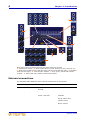
1
7
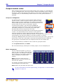
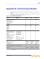
Signal flow
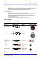
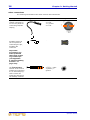
Connection(s)
Description
Notes
All primary outputs
Balanced XLR connectors,
50R source
Master channels
Aux, group, matrix,
monitor and local
(monitor) buses
Talk mic in talk mic
section of outputs (control
surface)
All secondary outputs
(direct outs)
Balanced Jack connectors,
50R source
Mono channels
Headphone outputs
Jack connectors, 10R
source (nominal +10dB)
local monitor section of
outputs (control surface)
Playback left and right
inputs and outputs
Unbalanced phono
connectors, 600R source
(nominal -10dB)
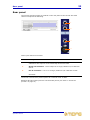
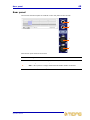
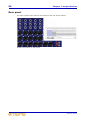
Rear panel
FireWire connections
FireWire (FW 4000 6-pin)
connector to IEEE1394
Rear panel
Power connections
IEC mains inlet
Rear panel
4-pin XLR lamp power
outlets
Under top edge of rear of
console
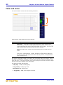
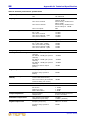
Signal flow
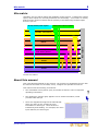
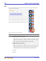
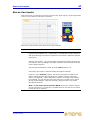
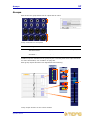
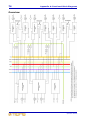
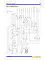
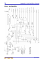
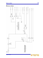
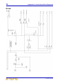
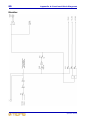
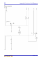
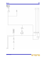
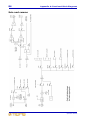
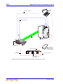
The following table gives an overview of the basic signal flow.
Channels or inputs
Route to
8, 16 or 24 mono mic/line channels
2 monitor, 4 aux, 4 group and 3 master
buses, and FireWire (8, 16 or 24
channels)
4 stereo mic channels
2 monitor, 4 aux, 4 group and 3 master
buses, and FireWire (8 channels)
4 stereo line inputs
The same numbered stereo channel and
then onwards (as above) or the stereo
master bus
2 stereo return channels
2 monitor, group 1-2 (return 1) and
group 3-4 (return 2), and the stereo
master buses
4 group channels
3 master and 2 matrix buses
3 master channels
2 matrix buses
4 aux channels
N/A
2 monitor channels
N/A
2 matrix channels
N/A
All channel types can also access the PFL, and AFL (left and right) solo buses.
VeniceF
Operator Manual