1
Оборудование для автосервиса http://www.motodok.com
Fault Code Manual
for
Mercedes-Benz
Analog Systems
1988-1997
Digital Systems
1993-2000
©Baum Tools Unlimited Inc. February 1, 2001
Оборудование для автосервиса http://www.motodok.com
Table of Contents
The Diagnostic Process
Information Gathering . . . . . . . . . . . . . . . . . . . . . . . . . . . . . . . . . . . . . . . . . . . . . . . . . . . . . . . . . . . . . . . . . . . .
4
Diagnostic Codes & Adaptation
Diagnostic Code Readout . . . . . . . . . . . . . . . . . . . . . . . . . . . . . . . . . . . . . . . . . . . . . . . . . . . . . . . . . . . . . . . . .
About Stored, Registered and Current Faults . . . . . . . . . . . . . . . . . . . . . . . . . . . . . . . . . . . . . . . . . . . . . . . . . . .
Fault Code Types . . . . . . . . . . . . . . . . . . . . . . . . . . . . . . . . . . . . . . . . . . . . . . . . . . . . . . . . . . . . . . . . . . . . . . .
Check Engine Light (MIL) Diagnosis . . . . . . . . . . . . . . . . . . . . . . . . . . . . . . . . . . . . . . . . . . . . . . . . . . . . . . . . .
Mixture Adaptation . . . . . . . . . . . . . . . . . . . . . . . . . . . . . . . . . . . . . . . . . . . . . . . . . . . . . . . . . . . . . . . . . . . . . . .
Resetting and Reactivating BOSCH Engine Control Module Memory . . . . . . . . . . . . . . . . . . . . . . . . . . . . . . . . .
Using the Data Stream . . . . . . . . . . . . . . . . . . . . . . . . . . . . . . . . . . . . . . . . . . . . . . . . . . . . . . . . . . . . . . . . . . . .
6
6
7
7
8
9
9
Equipment Connections
Connection Table . . . . . . . . . . . . . . . . . . . . . . . . . . . . . . . . . . . . . . . . . . . . . . . . . . . . . . . . . . . . . . . . . . . . . . .
Connector Layout of Vehicle Diagnostic Connector . . . . . . . . . . . . . . . . . . . . . . . . . . . . . . . . . . . . . . . . . . . . .
8-pole Diagnostic Connector . . . . . . . . . . . . . . . . . . . . . . . . . . . . . . . . . . . . . . . . . . . . . . . . . . . . . . . . .
16-pole Diagnostic Connector . . . . . . . . . . . . . . . . . . . . . . . . . . . . . . . . . . . . . . . . . . . . . . . . . . . . . . . . .
38-pin Diagnostic Connector . . . . . . . . . . . . . . . . . . . . . . . . . . . . . . . . . . . . . . . . . . . . . . . . . . . . . . . . .
9-pole Diagnostic Connector (1980-94) . . . . . . . . . . . . . . . . . . . . . . . . . . . . . . . . . . . . . . . . . . . . . . . . .
Mercedes Model Identifier
...............................................................
10
11
11
11
12
13
100
Fault Codes
Engine Control
Electronic Diesel Idle Speed Control (ELR) . . . . . . . . . . . . . . . . . . . . . . . . . . . . . . . . . . . . . . . . . . . . . . . . . . . .
Electronic Diesel System (EDS) . . . . . . . . . . . . . . . . . . . . . . . . . . . . . . . . . . . . . . . . . . . . . . . . . . . . . . . . . . . . .
Continuous Fuel Injection System (CFI) . . . . . . . . . . . . . . . . . . . . . . . . . . . . . . . . . . . . . . . . . . . . . . . . . . . . . . .
Continuous Fuel Injection System (MAS Controller) . . . . . . . . . . . . . . . . . . . . . . . . . . . . . . . . . . . . . . . . . . . . . .
LH Sequential Multiport Fuel Injection System - Analog . . . . . . . . . . . . . . . . . . . . . . . . . . . . . . . . . . . . . . . . . .
LH Sequential Multiport Fuel Injection System - Digital . . . . . . . . . . . . . . . . . . . . . . . . . . . . . . . . . . . . . . . . . . .
HFM Sequential Multiport Fuel Injection System - Analog . . . . . . . . . . . . . . . . . . . . . . . . . . . . . . . . . . . . . . . . .
HFM Sequential Multiport Fuel Injection System - Digital . . . . . . . . . . . . . . . . . . . . . . . . . . . . . . . . . . . . . . . . . .
PMS (PEC) Fuel Injection System . . . . . . . . . . . . . . . . . . . . . . . . . . . . . . . . . . . . . . . . . . . . . . . . . . . . . . . . . .
ME Sequential Multiport Fuel Injection System . . . . . . . . . . . . . . . . . . . . . . . . . . . . . . . . . . . . . . . . . . . . . . . . .
Diagnostic Module (DM) - Analog . . . . . . . . . . . . . . . . . . . . . . . . . . . . . . . . . . . . . . . . . . . . . . . . . . . . . . . . . . .
Diagnostic Module (DM) - Digital LH (104, 119, 120) . . . . . . . . . . . . . . . . . . . . . . . . . . . . . . . . . . . . . . . . . . . . .
Diagnostic Module (DM) - Digital HFM (104, 111) . . . . . . . . . . . . . . . . . . . . . . . . . . . . . . . . . . . . . . . . . . . . . . .
Base Module (BM) - LH-SFI . . . . . . . . . . . . . . . . . . . . . . . . . . . . . . . . . . . . . . . . . . . . . . . . . . . . . . . . . . . . . . .
Distributor Ignition (DI) - LH-SFI . . . . . . . . . . . . . . . . . . . . . . . . . . . . . . . . . . . . . . . . . . . . . . . . . . . . . . . . . . . .
Cruise Control/idle Speed Control (CC/ISC) w/o ASR . . . . . . . . . . . . . . . . . . . . . . . . . . . . . . . . . . . . . . . . . . . .
Electronic Accelerator / Cruise Control / Idle Speed Control (EA/CC/ISC) w/ASR . . . . . . . . . . . . . . . . . . . . . . .
14
14
15
16
17
18
20
22
25
26
41
43
45
47
48
49
50
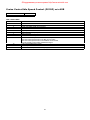
Chassis Control
Electronic Automatic Transmission Control (ETC) CFI (722.5) . . . . . . . . . . . . . . . . . . . . . . . . . . . . . . . . . . . . . .
Electronic Automatic Transmission Control (ETC) 1990-95 (722.5) . . . . . . . . . . . . . . . . . . . . . . . . . . . . . . . . . .
Automatic-engaged Four-wheel Drive (4MATIC) . . . . . . . . . . . . . . . . . . . . . . . . . . . . . . . . . . . . . . . . . . . . . . . .
Electronic Automatic Transmission Control (ETC) 1996-2000 (722.6) . . . . . . . . . . . . . . . . . . . . . . . . . . . . . . . .
Adaptive Damping System (ADS) . . . . . . . . . . . . . . . . . . . . . . . . . . . . . . . . . . . . . . . . . . . . . . . . . . . . . . . . . . .
Automatic Locking Differential (ASD) . . . . . . . . . . . . . . . . . . . . . . . . . . . . . . . . . . . . . . . . . . . . . . . . . . . . . . . . .
Anti-lock Brake System (ABS) . . . . . . . . . . . . . . . . . . . . . . . . . . . . . . . . . . . . . . . . . . . . . . . . . . . . . . . . . . . . . .
Anti-lock Brake system (ABS w/ASR) . . . . . . . . . . . . . . . . . . . . . . . . . . . . . . . . . . . . . . . . . . . . . . . . . . . . . . . .
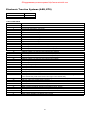
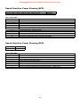
Electronic Traction Systems (ASR, ETS) . . . . . . . . . . . . . . . . . . . . . . . . . . . . . . . . . . . . . . . . . . . . . . . . . . . . . .
Speed Sensitive Power Steering (SPS) . . . . . . . . . . . . . . . . . . . . . . . . . . . . . . . . . . . . . . . . . . . . . . . . . . . . . . .
2
51
51
52
53
54
55
55
56
57
58
Оборудование для автосервиса http://www.motodok.com
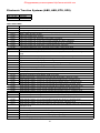
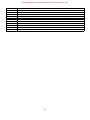
Electronic Traction Systems (ABS, ASR, ETS, SPS) Digital . . . . . . . . . . . . . . . . . . . . . . . . . . . . . . . . . . . . . . . 59
Body Control
Cabriolet Soft Top (CST) . . . . . . . . . . . . . . . . . . . . . . . . . . . . . . . . . . . . . . . . . . . . . . . . . . . . . . . . . . . . . . . . . 61
Roll Bar (RB) for CST . . . . . . . . . . . . . . . . . . . . . . . . . . . . . . . . . . . . . . . . . . . . . . . . . . . . . . . . . . . . . . . . . . . . 61
Roadster Soft Top (RST) . . . . . . . . . . . . . . . . . . . . . . . . . . . . . . . . . . . . . . . . . . . . . . . . . . . . . . . . . . . . . . . . 62, 63
Roll Bar (RB) for RST . . . . . . . . . . . . . . . . . . . . . . . . . . . . . . . . . . . . . . . . . . . . . . . . . . . . . . . . . . . . . . . . . . . . 63
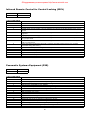
Infrared Remote Control For Central Locking (IRCL) . . . . . . . . . . . . . . . . . . . . . . . . . . . . . . . . . . . . . . . . . . . 64, 65
Pneumatic Systems Equipment (PSE) . . . . . . . . . . . . . . . . . . . . . . . . . . . . . . . . . . . . . . . . . . . . . . . . . . . . . . . . 65
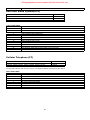
Anti-theft Alarm System( ATA) . . . . . . . . . . . . . . . . . . . . . . . . . . . . . . . . . . . . . . . . . . . . . . . . . . . . . . . . . . . . . . 66
Cellular Telephone (CT) . . . . . . . . . . . . . . . . . . . . . . . . . . . . . . . . . . . . . . . . . . . . . . . . . . . . . . . . . . . . . . . . . . . 66
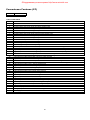
Convenience Features (CF) . . . . . . . . . . . . . . . . . . . . . . . . . . . . . . . . . . . . . . . . . . . . . . . . . . . . . . . . . . . . . . . . 67
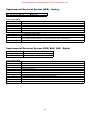
Supplemental Restraint System (SRS) . . . . . . . . . . . . . . . . . . . . . . . . . . . . . . . . . . . . . . . . . . . . . . . . . . . . . . . 68
Supplemental Restraint System (SRS) BAE, ZAE System . . . . . . . . . . . . . . . . . . . . . . . . . . . . . . . . . . . . . . . . . 68
Supplemental Restraint System (SRS) with Side Airbags . . . . . . . . . . . . . . . . . . . . . . . . . . . . . . . . . . . . . . . . . . 69
Body Control Systems (SRS, IRCL, PSE, ATA. RST, MSC, CF) Digital . . . . . . . . . . . . . . . . . . . . . . . . . . . . . . . 70
Climate Control
Tempmatic A/C . . . . . . . . . . . . . . . .
Automatic A/C . . . . . . . . . . . . . . . . .
A/C SELF DIAGNOSTIC SYSTEMS
TAU 2.1 . . . . . . . . . . . . . . . . . .
129 Chassis 1990-95 . . . . . . . .
129 Chassis 1996-99 . . . . . . . .
140 Chassis 1992-95 . . . . . . . .
140 Chassis 1996-99 . . . . . . . .
202 Chassis 1995 . . . . . . . . . .
202 Chassis 1996-99 . . . . . . . .
210 Chassis 1996-99 . . . . . . . .
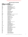
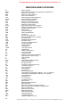
Mercedes Technical Acronyms
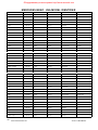
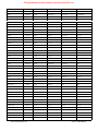
Mercedes Model Identifier
.........................................................
.........................................................
73
74
.
.
.
.
.
.
.
.
75
77
79
81
86
89
93
94
.
.
.
.
.
.
.
.
.
.
.
.
.
.
.
.
.
.
.
.
.
.
.
.
.
.
.
.
.
.
.
.
.
.
.
.
.
.
.
.
.
.
.
.
.
.
.
.
.
.
.
.
.
.
.
.
.
.
.
.
.
.
.
.
.
.
.
.
.
.
.
.
.
.
.
.
.
.
.
.
.
.
.
.
.
.
.
.
.
.
.
.
.
.
.
.
.
.
.
.
.
.
.
.
.
.
.
.
.
.
.
.
.
.
.
.
.
.
.
.
.
.
.
.
.
.
.
.
.
.
.
.
.
.
.
.
.
.
.
.
.
.
.
.
.
.
.
.
.
.
.
.
.
.
.
.
.
.
.
.
.
.
.
.
.
.
.
.
.
.
.
.
.
.
.
.
.
.
.
.
.
.
.
.
.
.
.
.
.
.
.
.
.
.
.
.
.
.
.
.
.
.
.
.
.
.
.
.
.
.
.
.
.
.
.
.
.
.
.
.
.
.
.
.
.
.
.
.
.
.
.
.
.
.
.
.
.
.
.
.
.
.
.
.
.
.
.
.
.
.
.
.
.
.
.
.
.
.
.
.
.
.
.
.
.
.
.
.
.
.
.
.
.
.
.
.
.
.
.
.
.
.
.
.
.
.
.
.
.
.
.
.
.
.
.
.
.
.
.
.
.
.
.
.
.
.
.
.
.
.
.
.
.
.
.
.
.
.
.
.
.
.
.
.
.
.
.
.
.
.
.
.
.
.
.
.
.
.
.
.
.
.
.
.
.
.
.
.
.
.
.
.
.
.
.
.
.
.
.
.
.
.
.
.
.
.
.
.
.
.
.
.
.
.
.
.
.
.
.
.
.
.
.
.
.
.
.
.
.
.
.
.
.
.
.
.
.
.
.
.
.
.
.
.
.
.
.
.
.
.
.
.
.
.
.
.
.
.
.
.
.
.
.
.
.
.
.
.
.
.
.
.
.
.
.
.
.
.
.
.
. . . . . . . . . . . . . . . . . . . . . . . . . . . . . . . . . . . . . . . . . . . . . . . . . . . . . . . . . . . 97
...............................................................
Mercedes Diagnostic Manuals
.
.
.
.
.
.
.
.
..........................................................
Technical Support Contact Information
100
106
. . . . . . . . . . . . . . . . . . . . . . . . . . . . . . . . . . . . . . . . . . . . . . . . . 107
DISCLAIMER: All information contained in this document is correct to the best of our knowledge. Errors may occur
therefore Baum Tools Unlimited Inc. makes no warrantee, guarantee or assurance that damage may not occur from the
use of this information. The user takes all responsibility for its use.
Mercedes Benz is a registered trademark of Daimler Chrysler AG.
Copyright © 1998-2001 BAUM TOOLS UNLIM ITED INC.
All rights reserved. Any reproduction in w hole or in part w ithout perm ission is strictly prohibited.
3
Оборудование для автосервиса http://www.motodok.com
This book is designed to help you in the basic diagnostic procedures for Mercedes Benz.
It is intended to be a starting point in the diagnostic process and is not intended to be a complete
resource.
THE DIAGNOSTIC PROCESS
The diagnostic process divides itself into several levels; Information Gathering, Analysis of Codes, Testing and then
Repair. W e will cover Information Gathering and Analysis of codes in this book.
For those experienced in diagnostics jump to page
INFORMATION GATHERING
The information gathering stage always starts with the Customer.
Step 1
The Customer Interview
This is truly an art.
It consists of getting the Customer to tell you what the complaint is and under what conditions it occurs.
The customer of course is, as always, the “MOST HELPFUL” source of information. Their concise insight into the
problem is a valuable step in getting the problem solved and the car back on the road. Also it’s the most fun part of
the diagnostic process. W atching the customer use body gestures, make funny faces and funny sounds in an attempt
to imitate vehicle noises can really brighten your day.
Actually the process of getting the information out of the customer can be relatively painless if you ask the correct
questions.
Here are
1)
2)
3)
4)
5)
6)
7)
some suggestions:
W hat is the problem/symptom(s)?
W hen did it start?
Under what conditions did the problem/symptom occur (if intermittent)? W et, dry, hot, cold or changing weather,
rough road,...etc.
Has there been any work done on the car recently? New radio, shocks, tires...etc?
Any jump starts or hard starts with long crank times.
Did you run out of gas recently?
Are you sure this hasn’t happened before, even for a short time?
Next the exact nature of the complaint must be addressed.
Step 2
The Test Drive
Go on a test drive with the Customer so you can/cannot experience the problem/symptom. This ensures that the
malfunction you try to diagnose and fix is the one with that the customer is concerned about and that it is a real
malfunction and not just a lack of understanding of normal vehicle operation.
Few things are more frustrating for you and the customer than repairing a suspension noise in the front of the car
(even if it did need new shocks, thrust bushings, brakes and a set of tires) when it was an engine noise that the
customer wanted fixed.
It is also a good idea to let the customer drive on the outbound leg so you can watch the customers driving technique.
The customer is more likely to be able to make the car “do it” then you will.
Sometimes a customer can mistake normal vehicle operation for a problem. An example of this is a customer whose
vehicle has an Anti-Lock Brake System (ABS), and is concerned because of a pulsating brake pedal when braking
hard. Since many people are unaware of this characteristic of normal ABS operation, they mistake this for a
malfunction.
Also if you start diagnosing a vehicle for a problem when the vehicle is operating normally, you can be in for a long
frustrating day.
4
Оборудование для автосервиса http://www.motodok.com
Step 3
Visually Inspect the Vehicle
Don’t leave out this step. You can save lots of time with this.
Engine - Look under the hood. Check for missing covers, oil and water splash, burn marks, nesting
materials, mis-routed wiring and anything else that looks out of place.
ABS/ASC/DSC/ASR - Lift hood and inspect the fluid level. Raise the car and inspect the brakes/wheels for
excess dust and corrosion. Check that all static charge grounding straps are in place.
Transmission - Look for beverage spillage on the center console area. Look for problems in the operation of
the instrument cluster and on-board computer. These systems share data with the engine, transmission and
traction systems. Inspect the transmission housing and connection cables.
SRS/Airbag - Has the car been in a collision, jumped a curb, been to the body shop (welded) or jump started.
Any or all of these can be signs of something amiss.
Remember you’re gathering information at this point so don;’t ignore anything at this step.
Step 4
Check the Battery
Visually inspect the battery for corroded cables and terminals. Also old batteries are pure trouble in a late model car.
If you see any problem clean it up and grab your DMM (Fluke 88, Vantage, or whatever volt meter you use) and ...
Check voltage Key Off Engine Off, KOEO and KOER.
Key Off Engine Off >11.4Volts
KOEO >11.4Volts
KOER >13.2 but not higher than 14.2volts
Step 5
Recall Fault Codes
Even without a “Check this or that Light” illuminated, pull the codes from all systems, not just the suspect system.
Late model cars have highly integrated controls and faults can cascade from one system to another. Simple things like
and wrong size tire can turn on the Transmission Failure message, yet not turn on the ABS or ASR light. Both
systems, though, may register codes.
Record and then Clear the codes.
W rite them down. W rite them down. W rite them down.
There is nothing more fun then the call to tech support that starts.
Technician:
“I got this code. Something about the O2 sensor. I replaced it but the code came back the next day.
W hy?”
Tech Support:
“W hat is the type and year of the car and what was the fault code number?”
Technician:
“It was a ‘94 C220, but I don’t remember the code number. It came in last week.”
Tech Support:
(Knocking back another bottle of Mallox) “Could it have been a Lambda Control code?”
Technician:
“Ya! I think that was it. W hy’d the new plugs make it go away and not the new O2 sensor?”
Test drive the car then pull the codes again. For some codes you will need to perform 2 test drives to get a code.
5
Оборудование для автосервиса http://www.motodok.com
Diagnostic Codes & Adaptation
Diagnostic Trouble Code (DTC) Readout:
The engine control module (N3/4) for the LH-SFI, HFM-SFI and ME-SFI systems are equipped with diagnostic trouble
code (DTC) memory. Malfunctions are recognized and stored as trouble codes and are distinguished as follows:
u
Malfunctions which are constantly present,
u
Malfunctions which occur longer than a pre determined number of seconds,
u
Intermittent contact malfunctions which have occurred 5x during a trip.
The DTC memory remains active even if the vehicle's battery is disconnected.
Malfunctions which are no longer present, are automatically erased again after a maximum of 19 trips.
Under HFM-SFI a TRIP has occurred if:
u
Engine running more than 5 minutes
u
Vehicle speed >4 km/h (2.5 mph),
u
Engine speed >700 rpm,
u
Engine shut off for 30 seconds.
Under ME-SFI a TRIP is
u
Engine running for more than 20 minutes,
u
Engine temperature is greater than -7 degrees C,
u
Engine speed is greater than 500 RPM,
The stored diagnostic trouble codes (DTCs) can be read at the 16 (124 E-class) or 38 pin data link connector (X11/4) with
the ignition switched "ON" or with the "engine running".
Diagnosis via an on-off ratio readout has been eliminated in all models.
About Stored, Registered and Current Faults
Stored or Permanent Faults - These faults generally turn on the MIL (malfunction indicator lamp previously known as
the Check Engine Light) and are recorded in the permanent memory of the cars system controller. Clearing these codes
most often will extinguish the MIL. (See Registered Faults below.)
Registered or Pending Faults - These faults can keep the MIL on. These faults are recorded in the temporary memory
of the of the cars system controller. This temporary memory records the number of times a component fails. W hen a
certain number of failures has occurred the fault is moved to permanent storage and the Check Engine Light (MIL) will
be illuminated. On cars equipped with Fault Registers the Check Engine Light may stay on after the Stored or Permanent
Fault has been erased if another occurrence of the fault has happened since the original Permanent Fault was stored.
To ensure the MIL is extinguished, erase the Stored and Registered faults.
Current or Actual Faults - These faults are detected while the car is running at idle or speed. They represent components
currently failing or, in the case of HFM and LH systems, components not present. These codes cannot be erased, and
are only meaningful with the ignition on and the engine running. Codes found in this system with the KOEO have no
meaning. Components not present on the vehicle may be flagged as failing by the cars internal diagnostics due to the
generic nature of the cars software. This is particularly true in C-Class (202) cars.
6
Оборудование для автосервиса http://www.motodok.com
Fault Code Types
There are basically 2 code types. Component failure codes and System Malfunction or Logic codes.
Component Failure Codes are just that. The ECU specifically targets a “component” as failing. These codes make it easy
to spot the problem.
Some of these components are:
Oxygen Sensor
MAP
MAF
TPS
Vehicle Speed Sensor
Coolant Temperature Sensor
Intake Air Temperature Sensor
Camshaft Position Sensor
Crankshaft Position Sensor
Exhaust Temperature Sensor
Injectors
Ignition (coils)
Idle Air Valve
Pressure Regulator (optional)
EGR Valve
EVAP Purge Valve
Secondary Air Valve
Secondary Air Pump...etc.
System Failure or Logic Codes indicate that, when the “system” operated it did not produce the desire result.
Examples of these codes are;
Fuel Trim, O2 Control at Limit (Lambda control)
Possible cause: Fuel tank ran empty, Incorrect Fuel Pressure, Injector valve defective or coked, Engine
Temperature Sensor defective, EGR valve leak, Secondary air leak, EVAP control system defective, Air Mass
Meter defective, O2 sensor aging (slow response) or inactive, Combustion disturbed by mechanical failure
(Spark plugs, compression, intake/exhaust valves, ...etc.)
Ignition Feedback Fault
Possible cause: Coils, Sparkplug W ires, Sparkplugs, ECU, Low or high battery voltage.
ASR CAN Signal to Another Controller Lost.
Possible cause: ABS/ASR Control Unit Fault, ABS/ASR Component Fault, CAN Bus Communications Fault,
Faulty Electronic Accelerator (EA) controller, Faulty EA Actuator, Low or high battery voltage.
Electronic Accelerator Fuel Cutoff Signal to Engine Control
Possible cause: Faulty EA Actuator System, Faulty EA Actuator, Low or high battery voltage
ECU Faults
Internal
Internal
Internal
Internal
Internal
Control
Control
Control
Control
Control
Module,
Module,
Module,
Module,
Module,
internal communication fault
Keep Alive Memory (CMOS)
Memory check sum (ROM/RAM)
RAM
EEPROM.
Load Calculation Cross Check, Range/Perf....etc.
These types of codes are more difficult to diagnose, but generally there will be other conditions that can give you a clue.
Other fault codes will be present, physical engine condition (wear and tear), nature of the complaint itself, and information
from the datastream can help refine your analysis.
7
Оборудование для автосервиса http://www.motodok.com
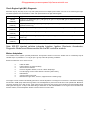
Check Engine Light (MIL) Diagnosis
Mercedes S(140), SL(129), E(124, 210) and C(202) class have multiple systems which can turn on an Check Engine Light.
All related systems must be tested for codes and repaired before the light will extinguish.
Injection System Diagnostic Socket Pin and CS1000 System to Use
129 LH
(1992-95)
LH (pin 4 & 5), EA/CC/ISC (pin 7), BM (pin 8), DI (pin 17 & 18) and DM (pin 19 check stored and
registered codes only)
140 LH
(1992-95)
LH (pin 4), EA/CC/ISC (pin 7), BM (pin 8), DI (pin 17) and DM (pin 19 check stored and
registered codes only)
124 HFM
(1993-95)
HFM (pin 8), EA/CC/ISC (pin 14), and DM (pin 3 check stored and registered codes only)
140 HFM
(1993-96)
HFM (pin 4), EA/CC/ISC (pin 7) and DM (pin 19 check stored and registered codes only)
202 HFM
(1995-96)
HFM (pin 4), EA/CC/ISC (pin 7) (except C220) and DM (pin 19 check stored and registered
codes only)
210 HFM
(1996-97)
HFM (pin 4), EA/CC/ISC (pin 7) and DM (pin 19 check stored and registered codes only)
Note: ME-SFI injected vehicles integrate Injection, Ignition, Electronic Accelerator,
Diagnostic Module and Base module into the ME controller module.
Mixture Adaptation:
The Lambda control system precisely determines fuel injection duration so that the fuel/air ratio is consistently kept at
Lambda equal 1 (Lambda=1 is 14.7 kg air per 1 kg fuel) under all operating conditions.
Should a malfunction occur in the form of:
u
u
u
u
u
u
u
u
Intake air leaks
Injector defects or carbon build-up,
Air Flow Sensor defects
Pressure regulator defects, such as a blown diaphragm.
Fuel tank purge control valve defects or EVAP system leaks.]
EGR defects
Vacuum leaks of any kind.
Mechanical engine wear, such as, chipped valves or leaking rings.
The engine control module automatically performs a mixture adjustment. The degree of correction is calculated constantly
and stored in KAM (Keep Alive Memory) RAM. The self-adaptation is performed at idle and under partial load. Maximum
correction towards rich or lean is 25%. After repair work is performed, the engine control module will automatically adapt
itself again after approx. 10 trips. After eliminating a malfunction or after trial installation of an engine control module from
another vehicle, the self-adaptation feature must be reset to its mean value.
8
Оборудование для автосервиса http://www.motodok.com
"Resetting and Reactivating for BOSCH Engine Control Module Memory"
For LH & HFM systems only.
To reset and reactivate the module :
1.
Read and clear all fault codes
2.
After display of 1 (No faults present) short the diagnostic plug (pin 8 for 16 pin diagnostic socket, pin
4 for 38 pin diagnostic socket) to ground for 6 to 8 seconds
3.
Switch ignition off and wait at least 5 seconds
4.
Turn ignition on, wait minimum of 10 seconds then restart engine.
Long Term Adaptation (Additive) - Engine at idle.
Short Term Adaptation (Multiplicative) - Engine at partial load
The correction towards rich or lean is + - 1.0 msec (Injection Duration) at idle and the factor of 0.68-1.32 at partial load.
After repair work is performed the engine control will automatically adapt itself again (ME injection) over the course of 10
TRIPS.
Codes Present in the Absent of Trouble Light
Not all control systems will trigger codes or turn on malfunction lights when codes are stored.
INJECTION/IGNITION system problems will trigger trouble codes, but may not turn on the MIL unless the fault results
in a change in the exhaust gases or can damage the engine in the short term. Also some mechanical problems in
earlier cars (pre 1988-96) can cause poor drivability without ever tripping a code or turning on the light. On later
models that is much less likely.
BRAKING/TRACTION systems will only turn on their check light when the system has become inactive. It does not
mean there isn’t a problem and codes haven’t been stored.
TRANSMISSION systems will turn on the “Check Engine” light if any shared system is detected as failing test.
AIRBAG and RESTRAINT SYSTEMS will turn on the light and record codes if incorrectly coded for the car. A good
example is the 1995 C280 and the 1995 S320. The same controller is used in both vehicles, however the S-class has
more features in the Airbag system such as side bags and baby seat detection. The coding of the controller for the
C280 masks the features not present so the controller doesn’t register a code. The controllers generally come off the
parts dept. shelf coded for maximum features.
In All Systems low or high battery voltages can trigger invalid or multiple codes without real failures of the indicated
components. Always check the battery condition before starting analysis.
Using the Data Stream to Diagnose/Confirm Faults
The Serial Data Information Stream of the ECU is a “window” into the operation of the system under test. By looking at
the values of the suspect components in operation and the computed values of the ECU, we can build a picture of the
operation of the system and what is causing the fault. The interpretation of the Data Stream is beyond the scope of
this book. Please refer to the Diagnostic Manuals from Mercedes Benz for complete discussion of the topic.
The nominal values for all Mercedes vehicles 1990-2000 can be found in the Mercedes Engine Diagnostic Manual
Volume 1 Section A.
A listing of these manuals can be found at the end of this document.
Multiple system and component faults can almost always be traced to faulty wiring
harnesses or water damage.
9
Оборудование для автосервиса http://www.motodok.com
Connection Table
Test Lead of Cable
Red
Black
Yellow
Connection source
Power -To power supply socket or vehicle battery
Ground - To socket 1
To diagnostic test socket
Power supply (B+) socket on the vehicle Diagnostic Connectors
8-pole connector
16-pole connector
Use with the battery extension cable to the vehicle battery
Socket 16 (circuit 15 - ignition ON)*
Not present in some models. Use battery +.
38-pole connector
Socket 3 (circuit 30 - Battery+)
*Must be performed with the ignition ON to power up the scanner
Ground (-) socket on the vehicle Diagnostic Connectors
8-pole connector
16-pole connector
38-pole connector
socket 1
socket 1
socket 1
10
Оборудование для автосервиса http://www.motodok.com
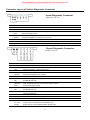
Connector Layout of Vehicle Diagnostic Connector
8-pole Diagnostic Connector
Models 201, 124, 126
1
2
3
4
5
6
7
8
CIS-E
ELR
EDS
ASD
4MATIC
SRS
A/C
Ground
Not used
Continuous fuel injection system (CFI)
Diesel injection system - Electronic idle speed control system
Electronic diesel system
Automatic locking differential
Automatic-engaged four wheel drive (124 only)
Supplemental Restraint System
Air Conditioning
Not used
16-pole Diagnostic Connector
Models 124, 129
1
2
3
4
5
6
7
8
9
10
11
12
13
14
OBD
CIS-E
DM
EDS
ASD
4MATIC
SRS / AB
A/C
RB
DI
HFM-SFI
PEC
ADS
RB
RST
ATA
IRCL
ETC
EA
CC / ISC
ESCM
Ground
Push-button for On Board Diagnostic (California only)
Continuous Fuel injection system (CFI)
Diagnostic Module - LED (California only)
Electronic diesel system
Automatic locking differential
Automatic-engaged four wheel drive
Supplemental Restraint System / Air Bag
Air Conditioning (Model 124)
Roll Bar (Model 129)
Distributor ignition
HFM Sequential multi-port Fuel Injection/Ignition system
Pressurized engine control
Adaptive Damping System
Roll Bar (Model 124)
Roadster Soft Top (Model 129)
TN-signal (Gasoline)
Anti Theft Alarm system
Infrared Remote Central Locking
Electronic automatic Transmission Control
Electronic Accelerator (Model 124)
Cruise Control / Idle Speed Control (Model 124)
Engine System Control Module (MAS), (Model 129)
11
Оборудование для автосервиса http://www.motodok.com
15
16
Not used
Voltage, Ignition ON (Circuit 15) (Not equipped on all models.)
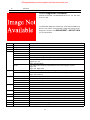
38-Pin Diagnostic Connector
Models 124.034/036, 129.058/063/067/076, 140, 170, 202, 208,
210, 215, 220
The Mercedes Diagnostic “Mushroom” #140-1463 available from
Baum Tools Unltd. is recommended to allow easy access to the
diagnostic connector. Call
for more information.
Pin
1
2
3
4
System
Ground (Terminal 31)
Voltage, terminal 87
Voltage, terminal 30
EDS
IFI
DFI
HFM-SFI
LH-SFI
ME-SFI
5
LH-SFI
ME-SFI
6
ABS
ETS
ASR
ESP
EA
ISC
CC
BM
BAS
ASD
EATC
ETC
ADS
SPS
TD
7
8
9
10
11
12
13
800-848-6657 or 941-927-1414
Description
W 12 (Chassis Ground), W 15 (Electronics Ground)
Ignition Switch 12volts +
Battery 12volts +
Electronic Diesel System
In-line Fuel Injection
Electronic Distributor-type Fuel Injection (Diesel)
Hot-Film Engine Management Sequential Multiport Fuel Injection/ignition
LH Sequential Multiport Fuel Injection System
Engines 104, 119
Engine 120 Right Bank
Motor Electronics with Sequential Multiport Fuel Injection/ignition System
Engine 119
Engine 120, Right Bank
LH Sequential Multiport Fuel Injection, Engine 120 Left Bank
Motor Electronics with Sequential Multiport Fuel Injection/ignition System
Engine 120 Left Bank
Anti-lock Brake System
Electronic Traction System
Acceleration Slip Regulation
Electronic Stability Program
Electronic Accelerator+
Idle Speed Control
Cruise Control/idle Speed Control
Base Module
Brake Assist
Automatic Locking Differential, Models 124, 129, 140
Electronic Automatic Transmission Control (5-speed AT) (722.6)
Electronic Transmission Control (722.6)
Adaptive Damping System
Speed-sensitive Power Steering
Speed Signal (Time Division) (Di) (Diesel) Models 202, 210
12
Оборудование для автосервиса http://www.motodok.com
14
15
16
17
18
19
20
21
22
23
24-25
26
27
28
29
30
31
32-33
34
35
36
36
37-38
TNA
TN
Lambda on/off ratio
Lambda on/off ratio
IC
HEAT
TA/C
AA/C
DI
TD
TN
DI
DM
PSE
MFCM
CF
RST
RB
ATA
ASD
PTS
AB
RCL
CNS
STH
ZUH
-
Signal (Gasoline) on LH-SFI
Speed Signal (DI/KSS) (Gasoline) on HFM-SFI, ME-SFI
LH-SFI Engine 119,
LH-SFI Engine 120 LH-SFI, Right Bank
LH-SFI Engine 120 Left Bank
Instrument Cluster
Automatic Heater
Air Conditioning (Tempmatic)
Air Conditioning (Automatic)
Distributor Ignition, Engines 104, 119, Engine 120, Right
Speed Signal (Time Division) (Di) (Diesel) Model 140
Speed Signal (DI/KSS) (Gasoline) on LH-SFI / model 202 HFM-SFI
Distributor Ignition, Engine 120, Left
Diagnostic Module
Pneumatic System Equipment, Model 140
Multi-function Control Module, Model 210
Convenience Feature, Model 140
Roadster Soft Top, Model 129
Roll Bar, Model 129
Anti-theft Alarm
Automatic Locking Differential, Model 202
Parktronic System, Model 140
Airbag/emergency Tensioning Retractor
Remote Central Locking
Communication and Navigation System
Stationary Heater
Heater Booster
The following connector is not for use with the CS1000 or CS2000 scanners
9-Pole Diagnostic Connector (1980-94)
The 9-pole Diagnostic Connector is used on earlier model vehicles. It can display on-off
ratio fault codes (1986-1992), RPM and Lambda sensor values. Various on-off ratio
Meters are available that provide access to this type of diagnostic connector. Call Baum
Tools at 800-848-6657 or 941-927-1414 for more information on these meters.
13
Оборудование для автосервиса http://www.motodok.com
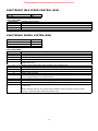
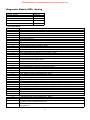
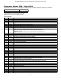
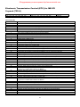
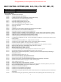
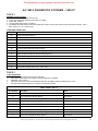
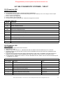
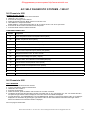
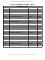
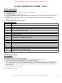
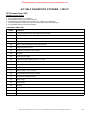
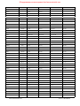
ELECTRONIC IDLE SPEED CONTROL (ELR)
Model
201.126
Model Year
1989
FAULT CODE TABLE
DTC Readout
Possible Cause of Failure
1
No fault found
2
Speed sensor signal
3
Coolant temperature sensor signal
4
ELR control unit or Idle speed control (ISC) system
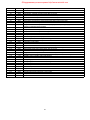
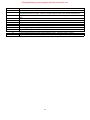
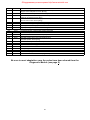
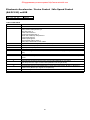
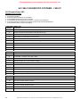
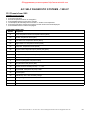
ELECTRONIC DIESEL SYSTEM (EDS)
Model
124.128
126.134 126.135
140.134
Model Year
1990-93
1990-91
1992-93
FAULT CODE TABLE
DTC Readout
Possible Cause of Failure
1
No fault found
2
Fuel rack position sensor (L7)
3
Air flow sensor signal (B2/1)
4
Electronic diesel system (EDS) control unit (N39) or atmospheric pressure sensor
5
Exhaust gas recirculation (EGR) valve vacuum transducer (Y31/1) or fault in exhaust gas recirculation
(EGR) control circuit
6
7
8
9
10
11
12
13
14
15
Electronic diesel system (EDS) control unit (N39), internal voltage supply
Starter ring gear speed sensor (L3)
Engine coolant temperature sensor (B11/4)
Intake air temperature sensor (B2/1a)
Voltage supply insufficient
Electronic idle speed control actuator (Y22) or exhaust gas recirculation (EGR) valve vacuum transducer
(Y31/1) or Boost pressure cut-out switchover valve
Not used
Electronic diesel system control unit (N39), faulty (internal fault memory)
Electronic diesel system pressure sensor (B5/1), defective
Boost pressure control/ pressure control flap vacuum transducer (Y31/5) , or defect in Boost pressure
control circuit.
Or
Intake manifold air pressure control valve vacuum transducer (Y31/2), wastage vacuum transducer
(Y31/3), or malfunction Intake manifold air pressure circuit
14
Оборудование для автосервиса http://www.motodok.com
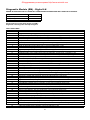
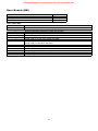
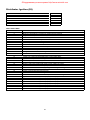
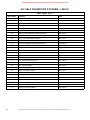
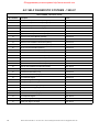
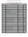
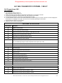
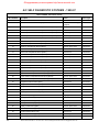
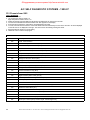
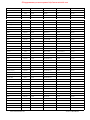
CONTINUOUS FUEL INJECTION SYSTEM (CFI)
Models
107.048
124.026 124.030 124.050 124.090
126.024 126.025
126.035 126.039 126.045
201.028 (1988-93) 201.029
124.026 124.030 124.051 124.090 124.230 124.290
126.024 126.025
129.061 129.066
201.029
Model Years
1988-91 (California version only)
1988-89 (California version only)
1988-89 (California version only)
1988-91 (California version only)
1988-89 (California version only)
1990-93
1990-93
1990-92
1990-93
FAULT CODE TABLE
DTC Readout
Possible Cause of Failure
1
No fault found
2
Throttle position switch - wide open throttle (WOT), signal faulty
3
Engine coolant temperature sensor faulty
4
Air flow sensor position potentiometer voltage illogical
5
Oxygen sensor signal illogical
6
Not used
7
TNA/TD signal (RPM) read by CFI control module
8
Altitude pressure signal from ignition control module illogical
9
Electronic hydraulic actuator (EHA) current faulty.
10
Throttle position switch - closed throttle position fault (idle)
11
Air injection system, open or short circuit
12
Absolute pressure values from EZL ignition control module are illogical
or
Exhaust gas recirculation temperature sensor
13
Intake air temperature reading is illogical
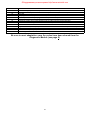
14
15
16
17
18
19
20
21
22
23
24
25
26
27
28
Vehicle speed signal read by CFI control module is illogical
Not used
Exhaust gas recirculation switchover valve, open or short circuit
Oxygen sensor is shorted to positive or ground
Current to idle control valve is illogical
Not used
Not used
Not used
Oxygen sensor heater voltage illogical
Short circuit to positive in purge switchover valve circuit
Not used
Short circuit to positive in start valve circuit
Short circuit to positive in upshift delay solenoid valve circuit
Data exchange between CFI control module and ignition control module interrupted
Intermittent contact in engine coolant temperature sensor circuit
29
30
31
32
33
34
CFI and ignition control module reading different engine coolant temperatures - Faulty sensor or wires
Not used
Intermittent contact in engine coolant temperature sensor circuit
Not used
Not used
Engine coolant temperature read from ignition control module illogical
15
Оборудование для автосервиса http://www.motodok.com
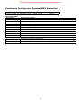
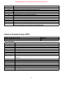
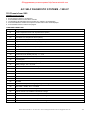
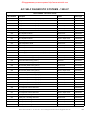
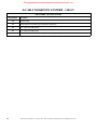
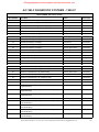
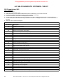
Continuous Fuel Injection System (MAS Controller)
Models
124.026 124.030 124.090 124.230 124.290 129.066 201.029
FAULT CODE TABLE
DTC Readout
1
2
3
4
5
6
7
8
9
10
11
12
13
14
15
Model Years
1990-92
Possible Cause of Failure
No fault found
Fuel pump relay (circuit 87) not functioning
TN/TD signal (RPM) interrupted
Output for oxygen sensor heater control defective
Output for air injection pump control defective
Output for kickdown switch control defective
Not used
Engine coolant temperature sensor signal out of range
Circuit 50 failure
Output failure of the start valve
A/C compressor engagement signal missing (87Z)
Output for A/C compressor control defective
Excessive A/C compressor clutch slippage
Vehicle speed signal illogical
Short circuit detected in fuel primp circuit
16
Оборудование для автосервиса http://www.motodok.com
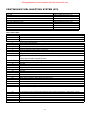
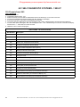
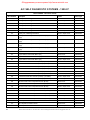
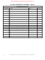
LH Sequential Multiport Fuel Injection - Analog
Models
140.032 140.057 140.076
124.034 124.036
129.067
140.042 140.043 140.051
Model Years
1992-93
1992-93
1992-93
1992-93
See digital LH injection page 18 for models 3/93 and later.
FAULT CODE TABLE
DTC Readout
1
2
3
4
5
6
7
8
9
10
11
12
13
14
15
16
17
18
19
20
21
22
23
24
25
27
29
Possible Cause of Failure
No fault found
Engine coolant temperature sensor circuit 1, open or short circuit.
Engine coolant temperature sensor circuit 2, open or short circuit.
Voltage at mass air sensor (MAF) with hot wire circuit insufficient or too high. Open or short circuit in
ground wire.
Not used
Not used
TNA-signal (rpm signal ) incorrect or open or short circuit.
Camshaft position sensor signal. Open or short circuit.
Starter signal (circuit 50) missing, open or short circuit.
Closed throttle position recognition from electronic accelerator control unit, short circuit.
Secondary air injection system, open or short circuit.
Burn-off control for mass air sensor with hot-wire, open or short circuit.
Intake air temperature sensor, open or short circuit.
Not used
Not used
Exhaust gas recirculation (EGR) switchover valve, open or short circuit.
CAN data: Electronic accelerator control module - no data transmission
CAN data: Ignition control module - no data transmission from DI module
Left LH-SFI control module no data transmission to right LH-SFI control module
LH-SFI control module - no data transmission
Oxygen sensor open circuit.
Oxygen sensor heater, open or short circuit.
Purge switchover valve, open or short circuit.
Left adjustable camshaft timing solenoid (Y49/1), open or short circuit
Adjustable camshaft timing solenoid, open or short circuit.
Injectors, open or short circuit.
I GR Start relay module (K29/1), open or short circuit
17
Оборудование для автосервиса http://www.motodok.com
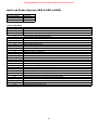
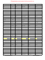
LH Sequential Multiport Fuel Injection - Digital
Engines
104 119 120
Model Years
1992-1995
Also check for codes in the Diagnostic Module (DM page 43), Electronic Accelerator/Cruise Control (EA/CC/ISC pages 50 and 49),
Distributor Ignition (DI page 48) and the Base Module (BM page 47).
(These fault codes numbers are only for the CS1000 Code Scanner. They are different from those found in the Mercedes Benz
original Diagnostic Manual fault code tables.)
LH-SFI “Stored” Fault Codes
DTC Readout
Possible Cause of Failure
002
Engine coolant temperature sensor circuit 1, short or open circuit
003
Engine coolant temperature sensor circuit 2, short or open circuit
004
Voltage of Hot Wire MAF sensor too low or too high or ground wire has open circuit.
005
Not used.
006
Japan only Exhaust temperature sensor, circuit short or open
007
TNA-signal (rpm signal ) incorrect or open or short circuit.
008
Camshaft position sensor signal. Open or short circuit.
009
Starter signal (circuit 50) missing, open or short circuit.
010
Closed throttle position recognition from electronic accelerator control unit, short circuit.
011
Secondary air injection system, open or short circuit.
012
Burn-off control for mass air sensor with hot-wire, open or short circuit.
013
Intake air temperature sensor, open or short circuit.
014
Not used.
015
Not used.
016
EGR switchover valve, circuit open or short
017
CAN data: Electronic accelerator control module - no data transmission
018
CAN data: Ignition control module - no data transmission from DI module
019
Left LH-SFI control module no data transmission to right LH-SFI control module
020
LH-SFI control module - no data transmission (Left or Right)
021
Oxygen sensor open circuit.
022
Oxygen sensor heater, open or short circuit.
023
Purge switchover valve, open or short circuit.
024
Left adjustable camshaft timing solenoid (Y49/1), open or short circuit (119 only)
025
Adjustable camshaft timing solenoid, open or short circuit.
026
Upshift Delay Switchover Valve, open or short circuit
027
Injectors, open or short circuit.
028
LH Control Module incorrectly coded or open circuit.
029
1GR Start relay module (K29/1), open or short circuit
These codes require special scanners to access.
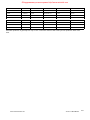
LH-SFI “Current” Fault Codes
DTC Readout
Possible Cause of Failure
001
Injector, cylinder 1 circuit short to positive
002
Injector, cylinder 5 circuit short to positive
003
Injector, cylinder 4 circuit short to positive
004
Injector, cylinder 8 circuit short to positive
005
Injector, cylinder 6 circuit short to positive
006
Injector, cylinder 3 circuit short to positive
007
Injector, cylinder 7 circuit short to positive
008
Injector, cylinder 2 circuit short to positive
009
Injector, cylinder 1 open circuit or short to ground
010
Injector, cylinder 5 open circuit or short to ground
011
Injector, cylinder 4 open circuit or short to ground
18
Оборудование для автосервиса http://www.motodok.com
DTC Readout
012
013
014
015
016
017
018
019
020
021
022
023
024
025
026
027
028
029-030
031
032
033
034
035
036
037
038
038
040
041
042
043
044
045
046
047
048
049
050
051
052
053
054
055
056
Possible Cause of Failure
Injector, cylinder 8 open circuit or short to ground
Injector, cylinder 6 open circuit or short to ground
Injector, cylinder 3 open circuit or short to ground
Injector, cylinder 7 open circuit or short to ground
Injector, cylinder 2 open circuit or short to ground
HFM sensor Voltage too high or too low, may open circuit
Engine coolant temperature sensor short or open circuit
Engine coolant temperature sensor short or open circuit
Engine coolant temperature sensor signal questionable
Intake air temperature sensor short or open circuit
Exhaust temperature sensor short or open circuit (Japan version only)
CO potentiometer open circuit (non KAT)
LH-SFI control unit coding plug open circuit (not USA version)
Starter signal missing (circuit 50), may short or open circuit
Idle speed recognition from Cruise control/Electronic accelerator (CC/EA), circuit short to ground
Not used
O2S 1 signal, short or open circuit
Not used
O2S 2 signal, short or open circuit
Not used
CAN communication problem, No communication from LH control unit
CAN communication problem, No communication from ASR control unit
CAN communication problem, No communication from LH control unit
CAN communication problem, No communication from LH control unit
CAN communication problem, No communication from EZL/AKR ignition control unit
CAN communication problem, No communication from EZL/AKR ignition control unit
CAN communication problem, No communication from Cruise control/Electronic accelerator
Not used
Air injection system short or open circuit
Fuel purge switchover valve open or short circuit
Transmission switchover valve, circuit open or short
EGR switchover valve, circuit open or short
Camshaft timing adjust solenoid, circuit open or short
Camshaft timing adjust solenoid, circuit open or short
First gear start relay, circuit open or short
Not used
Air injection system circuit short or open
Fuel purge switchover valve circuit short or open
Transmission switchover valve relay or solenoid, circuit short or open
EGR switchover valve circuit short or open
camshaft timing Adjust solenoid circuit short or open
camshaft timing Adjust solenoid circuit short or open
First gear start relay circuit short or open
Not used
19
Оборудование для автосервиса http://www.motodok.com
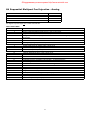
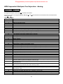
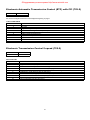
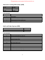
HFM Sequential Multiport Fuel Injection - Analog
Engines
104 111
Model Year
1993
See digital HFM injection section page 22 for models 3/93 and later.
Also check for codes in the Diagnostic Module (DM page 41 and 43) and the Electronic Accelerator/Cruise Control (EA/CC/ISC
pages 50 and 49).
FAULT CODE TABLE
DTC Readout
Possible Cause of Failure
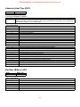
1
No fault found
2
Engine Coolant temperature sensor
3
Intake air temperature sensor
4
Hot film mass air flow sensor
5
CTP switch
6-7
Not used
8
Idle speed control (ISC) system at upper or lower control stop or CC or EA indicates "limp home" mode.
9
O2S 1 (before TWC) - voltage too high, circuit open or voltage implausible
10
O2S 2 (after TWC)voltage too high, circuit open or voltage implausible
11
O2S 1 heater (before TWC) - Current too high/low or short circuit.
12
O2S 2 heater (after TWC) - Current too high/low or short circuit.
13
O2S (Lambda) control system operating at rich or lean limit
14
Injector, cylinder 1
15
Injector, cylinder 2
16
Injector, cylinder 3
17
Injector, cylinder 4
18
Injector, cylinder 5
19
Injector, cylinder 6
20
Self-adaptation at idle speed or upper/lower partial load at rich or lean limit
21
Ignition output 3 or ignition coil for cylinder 1 and 6
22
Ignition output 1 or ignition coil for cylinder 2 and 5 (Engine 111, cylinder 1 and 4)
23
Ignition output 2 or ignition coil for cylinder 3 and 4 (Engine 111, cylinder 2 and 3)
24
CKP sensor or magnet for position sensor not recognized
25
CMP sensor not recognized or implausible
26
Not used
27
TN-signal (rpm signal ) - open or short to ground
28
VSS - open circuit
29
Not used
30
Fuel pump relay module - open or short circuit
31
Not used
32
Knock sensors 1 and /or 2
33
Maximum retard setting on at least one cylinder has been reached or the ignition angle deviation between the
individual cylinders is greater than 6 degrees crankshaft angle
34
Knock control-output switch in engine control module faulty Momentary fault in self-adaptation closed throttle
speed/partial load
35
Model 124,129 and 140 AIR pump switchover valve and/or electromagnetic AIR pump clutch.
Model 202 AIR pump switchover valve and/or AIR relay module
36
Purge control valve - open/short to ground or B+
37
Transmission Upshift delay switchover valve (Y3/3) without function (Logic Chain) - Check vacuum and
adjust Bowden cable.
38
Adjustable camshaft timing solenoid - open/short to ground or B+
39
Exhaust gas recirculation switchover valve - open/short to ground or B+
40
Transmission overload protection switch - open/short to ground or B+ or open or closed or implausible
41
CAN communication from engine control module faulty
20
Оборудование для автосервиса http://www.motodok.com
DTC Readout
42
43
44
45
46
48
49
50
Possible Cause of Failure
CAN communication from ASR, EA/CC/ISC module or diagnostic module (OBD II) faulty
Starter signal (circuit 50) not present
Not used
Fuel safety shut-off of electronic accelerator or cruise control active
Resonance intake manifold switchover valve - open/short to ground or B+
O2S 2 (after TWC) heating circuit relay module - open/short to ground or B+
Voltage supply at engine control module implausible/low volts.
Engine control module faulty or not coded.
21
Оборудование для автосервиса http://www.motodok.com
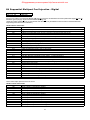
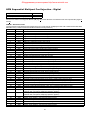
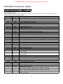
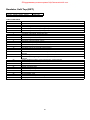
HFM Sequential Multiport Fuel Injection - Digital
Engines
111 (4 cylinder, 2.2/2.3L engine)
104 (6 cylinder, 2.8/3.2L engine)
Model Years
1994-97
1994-97
Also check for codes in the Diagnostic Module (DM page 43) and the Electronic Accelerator/Cruise Control (EA/CC/ISC pages 50
and 49).
HFM-SFI Stored Fault Codes
Only Stored Fault Codes illuminate the Check Engine Light. (Code Scanner will display the fault code numbers listed under OB15,
Mercedes factory numbers are listed under MB for referral to factory literature.)
OB15
MB
Description
0
No Fault Found
1
(002)
Engine Coolant Temperature Sensor - Short Circuit
2
(003)
Engine Coolant Temperature Sensor - Open Circuit
3
(004)
Engine Coolant Temperature Sensor - Signal Incorrect
(005)
Engine Coolant Temperature Sensor - Intermittent Contact
4
(006)
Intake Air Temperature Sensor, Short Circuit
5
(007)
Intake Air Temperature Sensor, Open Circuit
(008)
Intake Air Temperature Sensor - Intermittent Contact
6
(009)
Hot Film Air Mass Sensor - Signal Too High
7
(010)
Hot Film Air Mass Sensor - Open Circuit
8
(011)
Engine idle speed contact Throttle valve position too large
9
Not used
10
(012)
Engine idle speed contact air mass too large
11
(113)
HFM-SFI control unit not coded
12
(014)
Throttle valve potentiometer actual value too high.
13
(015)
Throttle valve potentiometer actual value too low.
14
(017)
Throttle valve potentiometer drive value implausibly high.
15
(018)
Throttle valve potentiometer drive value implausibly low.
16
(020)
ISC (Idle speed control) at lower control stop area, malfunction.
17
(021)
ISC (Idle speed control) at upper control stop area, malfunction.
18
(022)
CC,EFP actuator signals in limp home mode (emergency mode).
19
(023)
O2 sensor (before/upstream of Cat. Conv.), voltage too large.
20
(024)
O2 sensor (before/upstream of Cat. Conv.), open circuit
21
(025)
O2 sensor (before/upstream of Cat. Conv.), signal incorrect
22
(026)
O2 sensor (after/downstream of Cat. Conv.), voltage too large
23
(027)
O2 sensor (after/downstream of Cat. Conv.), open circuit
24
(028)
O2 sensor (after/downstream of Cat. Conv.), signal incorrect
25
(029)
O2 sensor heater (before/upstream of Cat. Conv.), heater current (amp) too small
26
(030)
O2 sensor heater (before/upstream of Cat. Conv.), heater current (amp) too large
27
(031)
O2 sensor heater (before/upstream of Cat. Conv.), heater current, short circuit
28
(032)
O2 sensor heater (after/downstream of Cat. Conv.), heating current (amp) too small
29
(033)
O2 sensor heater (after/downstream of Cat. Conv.), heating current (amp) too large
30
(034)
O2 sensor heater (after/downstream of Cat. Conv.), heating current, short circuit
31
(035)
Fuel adaptation (lambda) control, mixture too lean (rich stop)
(Intake air leak, fuel injectors, diaphragm pressure regulator)
32
(036)
Fuel adaptation (lambda) control, mixture too rich (lean stop)
(Intake air leak, fuel injectors, diaphragm pressure regulator)
33
(037)
Injection valve cylinder 1, short to positive
34
(038)
Injection valve cylinder 1, open circuit or short to ground
35
(039)
Injection valve cylinder 2, short to positive
36
(040)
Injection valve cylinder 2, open circuit or short to ground
37
(041)
Injection valve cylinder 3, short to positive
38
(042)
Injection valve cylinder 3, open circuit or short to ground
22
Оборудование для автосервиса http://www.motodok.com
OB15
39
40
41
42
43
44
45
MB
(043)
(044)
(045)
(046)
(047)
(048)
(049)
46
(050)
47
(051)
48
(052)
49
(053)
50
(054)
51
52
53
54
55
56
57
58
59
60
61
62
63
64
65
66
67
68
69
70
71
72
73
74
75
76
77
78
79
80
81
82-83
84
85
86
87-88
89
90
(061)
(062)
(063)
(055)
(056)
(057)
(058)
(059)
(060)
(064)
(065)
(066)
(067)
(068)
(069)
(070)
(071)
(072)
(073)
(074)
(076)
(077)
(079)
(080)
(081)
(082)
(083)
(084)
(085)
(086)
(087)
(088)
(089)
(090)
Description
Injection valve cylinder 4, short to positive
Injection valve cylinder 4, open circuit or short to ground
Injection valve cylinder 5, short to positive
Injection valve cylinder 5, open circuit or short to ground
Injection valve cylinder 6, short to positive
Injection valve cylinder 6, open circuit or short to ground
Self-adjustment too rich at Idle
(Intake air leak, fuel injectors, diaphragm pressure regulator, wear engine)
Self-adjustment too lean at Idle
(Intake air leak, fuel injectors, diaphragm pressure regulator, wear engine)
Self-adjustment too rich at Lower part load
(Intake air leak, fuel injectors, diaphragm pressure regulator, wear engine)
Self-adjustment too lean at Lower part load
(Intake air leak, fuel injectors, diaphragm pressure regulator, wear engine)
Self-adjustment too rich at Upper part load
(Intake air leak, fuel injectors, diaphragm pressure regulator, wear engine)
Self-adjustment too lean at Upper part load
(Intake air leak, fuel injectors, diaphragm pressure regulator, wear engine)
Ignition system output stage 3, Cylinder 1 misfires
Ignition system output stage 3, Cylinder 6 misfires
Ignition system output stage 3, Current value not reached
Ignition system output stage 1, Cylinder 2 misfires
Ignition system output stage 1, Cylinder 5 misfires
Ignition system output stage 1, Current value not reached
Ignition system output stage 2, Cylinder 3 misfires
Ignition system output stage 2, Cylinder 4 misfires
Ignition system output stage 2, Current value not reached
Crankshaft signal incorrect
Crankshaft signal Magnet missing or Number of teeth incorrect
Crankshaft signal Speed incorrect, too high
Camshaft signal incorrect/not recognized
HFM circuit/trimming plug short to ground
HFM circuit/trimming plug open circuit or short to positive
TN speed signal (rpm) Output short to ground
TN speed signal (rpm) Output short to positive
Vehicle speed signal not recognized, short circuit
Vehicle speed signal implausibly high, short circuit
PSV relay K3/1 circuit short to positive
Not used
Fuel pump relay open circuit or short circuit
Not used
CO potentiometer Input short to positive
Knock sensor 1 signal open circuit
Knock sensor 2 signal open circuit
Ignition timing max retardation reached at least one cylinder
Ignition angle deviation between the individual cylinders too high
Knock control analysis, HFM control unit defective
Short-term self-adjustment Idle/Part-load fault
Air pump relay-module/switch-valve output, open circuit or short circuit
Not used
Fuel purge switch-valve, open circuit/short circuit
Fuel purge switch-valve, short to positive
Transmission Upshift delay switchover valve (Y3/3) without function (Logic Chain)
Not used
Camshaft timing adjust actuator circuit short to positive
Camshaft timing adjust actuator open circuit or short to ground
23
Оборудование для автосервиса http://www.motodok.com
OB15
91
92
93
94
95
96
97
98
99
100
101
102
103
104
105
106
107
108
109
110
111
112
113
114
115
116
117
118
119
120
121
122
123
124
125
126
127-128
MB
(091)
(092)
(093)
(094)
(095)
(096)
(097)
(098)
(116)
(099)
(100)
(117)
(101)
(102)
(103)
(104)
(105)
(106)
(107)
(114)
(108)
(109)
(115)
(110)
(111)
(112)
(005)
(008)
(013)
(016)
(019)
(078)
Description
EGR switch-valve short to positive
EGR switch-valve open circuit or short to ground
Transmission overload protection switch short to ground
Transmission overload protection switch, circuit short or open
Transmission overload protection switch, circuit short or open
Transmission overload protection switch signal implausible
CAN problem Transmission communication from HFM control system faulty
CAN problem No data reception from ASR
CAN problem No data reception from IRCL. ( if equip with IRCL) Voltage supply at Circuit 87M, low
voltage or implausible (Starting 06/93)
Not used
CAN problem No data reception from EFP,TPM
CAN problem No data reception from Diagnosis Module
Not used
Attempt to start with IRCL locked
No starter signal (Terminal 50), open or short circuit
Thermocouple CAT B16/6 Temperature too high
Thermocouple CAT B16/6 Temperature too low
Fuel safety cut-off settled
Not used
Resonance intake manifold switchover valve, short to positive
Resonance intake manifold switchover valve, open circuit/short to ground
Ignition dwell angle control output stage, short to ground
HFM control unit identification illogical
Oxygen sensor heater (after/downstream of Cat. Conv.), short to positive
Oxygen sensor heater (after/downstream of Cat. Conv.), open circuit or short to ground
HFM-SFI control unit N3/4 coding bytes illogical
Not used
Voltage supply to HFM-SFI control unit, incorrect
Voltage supply at HFM-SFI control unit, voltage too low
HFM control unit faulty
Coolant temperature sensor, Loose contact
Intake air temperature sensor, Loose contact
Idle speed contact, Loose contact
Potentiometer throttle valve, Loose contact
Potentiometer throttle valve drive, Loose contact
CO potentiometer R33 Loose contact
Not used
24
Оборудование для автосервиса http://www.motodok.com
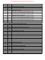
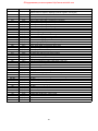
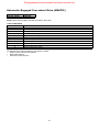
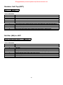
PMS (PEC) Fuel Injection - Digital
Engines
111 (4 cylinders, 1.8/2.0L engine)
Model Years
1994-97
PMS Stored Fault Codes
Only Stored Fault Codes illuminate the Check Engine Light.(Code Scanner will display the fault code numbers listed under OB15,
Mercedes factory numbers are listed under MB.)
OB15
MB
Description
001
(002)
Coolant temperature sensor, short circuit
002
(003)
Coolant temperature sensor, open circuit
003
(004)
Coolant temperature sensor, incorrect
004
(006)
Intake air temperature sensor, short circuit
005
(007)
Intake air temperature sensor, open circuit
006
(009)
PMS Control unit, Intake manifold pressure implausible
007
(010)
PMS Control unit, No Intake manifold pressure
008
(011)
Idle speed contact closed signal incorrect
009
(068)
Idle speed contact open circuit
010-011
Not used
012
(013)
Potentiometer throttle valve, value too high
013
(014)
Potentiometer throttle valve, value too low
014
(016)
Potentiometer throttle valve drive value too high/incorrect
015
(017)
Potentiometer throttle valve drive value too low/incorrect
016
(019)
Idle speed control at lower control stop area, malfunction
017
(020)
Idle speed control at upper control stop area, malfunction
018
(021)
Idle speed control in limp home-mode (emergency operation)
019
(022)
O2 sensor voltage too large
020
(023)
O2 sensor, open circuit
021
(024)
O2 sensor signal illogical
022
(069)
Exhaust flap short to positive
023
(070)
Exhaust flap open circuit or short to ground
024
Not used
025
(025)
O2 sensor heater current (amps) too small
026
(026)
O2 sensor heater current (amps) too large
027
(027)
O2 sensor heater, short circuit
028-030
Not used
031
(028)
Fuel adaptation (lambda) control mixture too lean (Intake air leak, fuel injectors, diaphragm
pressure regulator)
032
(029)
Fuel adaptation (lambda) control mixture too rich (Intake air leak, fuel injectors, diaphragm
pressure regulator)
033
(030)
Injection valve cylinder 1/4 short to positive
034
(031)
Injection valve cylinder 1/4 open circuit or short to ground
035
(032)
Injection valve cylinder 2/3 short to positive
036
(033)
Injection valve cylinder 2/3 open circuit or short to ground
037
(064)
Input signal from IFZ, open circuit or short to positive
038
(065)
Input signal from IFZ, short to ground
039
(066)
IFZ system unresponsive
040
(067)
Input signal from IFZ incorrect
041-044
Not used
045
(034)
Self-adjustment too rich at Idle
(Intake air leak, fuel injectors, diaphragm pressure regulator, wear engine)
046
(035)
Self-adjustment too lean at Idle
(Intake air leak, fuel injectors, diaphragm pressure regulator, wear engine)
047
(036)
Self-adjustment too rich at Part load (Intake air leak, fuel injectors, diaphragm pressure
regulator, wear engine)
25
Оборудование для автосервиса http://www.motodok.com
OB15
048
049-050
051
052
053
054
055
056
057-059
060
061
062
063
064
065
066
067
068
069
070
071
072
073
074
075 ~079
080
081
082
083
084
085
086
087 ~092
093
094-095
096
097 ~ 118
119
120
121
122
123
124
125
126
127-128
MB
(037)
(038)
(039)
(040)
(041)
(042)
(043)
(044)
(045)
(046)
(047)
(048)
(049)
(050)
(051)
(052)
(053)
(054)
(055)
(056)
(057)
(061)
(071)
(072)
(059)
(060)
(062)
(073)
(074)
(063)
(005)
(008)
(012)
(015)
(018)
(058)
Description
Self-adjustment too lean at Part load
(Intake air leak, fuel injectors, diaphragm pressure regulator, wear engine)
Not used
Ignition system output stage 1, short to positive
Ignition system output stage 1, Cylinder 1/4 misfires
Ignition system output stage 1, Amperage not achieved
Ignition system output stage 2, short to positive
Ignition system output stage 2, Cylinder 2/3 misfires
Ignition system output stage 2, Amperage not achieved
Not used
Crankshaft signal incorrect
Crankshaft signal Magnet missing or Numbers of teeth incorrect
Crankshaft signal Speed incorrect, too high
Not used
PMS circuit/trimming plug short to ground
PMS circuit/trimming plug open circuit or short to positive
TN speed signal (rpm) Output short to ground
TN speed signal (rpm) Output short to positive
Vehicle speed signal not recognized, short circuit
Vehicle speed signal too high, short circuit
PSV relay open circuit or short to positive
PSV relay short to ground
Fuel pump relay open circuit or short to positive
Fuel pump relay short to ground
CO potentiometer Input circuit short to positive
Not used
Short-term self-adjustment faulty at idle speed or part load
Rear axle ratio was changed
Rear axle ratio signal incorrect
Not used
Fuel purge switch-valve open circuit or short to positive
Fuel purge switch-valve short to ground
Transmission shifting delay/smooth switch-valve, open circuit or short circuit
Not used
Transmission protection short to ground or active too long
Not used
Transmission protection open circuit or short to positive
Not used
PMS control unit voltage supply too low
Not used
Coolant temperature sensor, Loose contact
Intake air temperature sensor, Loose contact
Idle speed contact, Loose contact
Potentiometer throttle valve, Loose contact
potentiometer throttle valve drive value, Loose contact
CO potentiometer circuit, Loose contact
Not used
26
Оборудование для автосервиса http://www.motodok.com
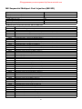
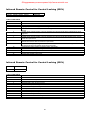
ME Sequential Multiport Fuel Injection (ME-SFI)
Engines
Model Years
104 (6 cylinders, 2.8/3.2L engine)
111 (4 cylinder 2.0, 2.2, 2.3L)
112 (V6 engine, 2.4/2.8/3.2L)
113 (V8 engine, 4.3, 5.0L)
119 (V8 engine 4.2/5.0L)
120 (12 cylinder engine)
8/968/968/978/988/95-1998
8/95-2000
ME-SFI ME Injection incorporates EA/CC/ISC, DM, DI and BM codes.
MB
ME Code Description
P00XX
Fuel and Air Metering and Auxiliary Emission Controls
P0010
A Camshaft Position Actuator Circuit (Bank 1)
P0011
A Camshaft Position - Timing Over-Advanced or System Performance (Bank 1)
P0012
A Camshaft Position - Timing Over-Retarded (Bank 1)
P0013
B Camshaft Position - Actuator Circuit (Bank 1)
P0014
B Camshaft Position - Timing Over-Advanced or System Performance (Bank 1)
P0015
B Camshaft Position - Timing Over-Retarded (Bank 1)
P0020
A Camshaft Position Actuator Circuit (Bank 2)
P0021
A Camshaft Position - Timing Over-Advanced or System Performance (Bank 2)
P0022
A Camshaft Position - Timing Over-Retarded (Bank 2)
P0023
B Camshaft Position - Actuator Circuit (Bank 2)
P0024
B Camshaft Position - Timing Over-Advanced or System Performance (Bank 2)
P0025
B Camshaft Position - Timing Over-Retarded (Bank 2)
P0030
H02S Heater Control Circuit (Bank 1) Sensor 1)
P0031
H02S Heater Control Circuit Low (Bank 1 Sensor 1)
P0032
H02S Heater Control Circuit High (Bank 1 Sensor 1)
P0033
Turbo Charger Bypass Valve Control Circuit
P0034
Turbo Charger Bypass Valve Control Circuit Low
P0035
Turbo Charger Bypass Valve Control Circuit High
P0036
H02S Heater Control Circuit (Bank 1 Sensor 2)
P0037
H02S Heater Control Circuit Low (Bank 1 Sensor 2)
P0038
H02S Heater Control Circuit High (Bank 1 Sensor 2)
P0042
H02S Heater Control Circuit (Bank 1 Sensor 3)
P0043
H02S Heater Control Circuit Low (Bank 1 Sensor 3)
P0044
H02S Heater Control Circuit High (Bank 1 Sensor 3)
P0050
H02S Heater Control Circuit (Bank 2 Sensor 1)
P0051
H02S Heater Control Circuit Low (Bank 2 Sensor 1)
P0052
H02S Heater Control Circuit High (Bank 2 Sensor 1)
P0056
H02S Heater Control Circuit (Bank 2 Sensor 2)
P0057
H02S Heater Control Circuit Low (Bank 2 Sensor 2)
P0058
H02S Heater Control Circuit High (Bank 2 Sensor 2)
P0062
H02S Heater Control Circuit (Bank 2 Sensor 3)
P0063
H02S Heater Control Circuit Low (Bank 2 Sensor 3)
P0064
H02S Heater Control Circuit High (Bank 2 Sensor 3)
P0065
Air Assisted Injector Control Range/Performance
P0066
Air Assisted Injector Control Circuit or Circuit Low
P0067
Air Assisted Injector Control Circuit High
P0070
Ambient Air Temperature Sensor Circuit
P0071
Ambient Air Temperature Sensor Range/Performance
P0072
Ambient Air Temperature Sensor Circuit Low Input
P0073
Ambient Air Temperature Sensor Circuit High Input
P0074
Ambient Air Temperature Sensor Circuit Intermittent
P0075
Intake Valve Control Solenoid Circuit (Bank 1)
27
Оборудование для автосервиса http://www.motodok.com
MB
P0076
P0077
P0078
P0079
P0080
P0081
P0082
P0083
P0084
P0085
P0086
P01XX
P0100
P0101
P0102
P0103
P0104
P0105
P0106
P0107
P0108
P0109
P0110
P0111
P0112
P0113
P0114
P0115
P0116
P0117
P0118
P0119
P0120
P0121
P0122
P0123
P0124
P0125
P0126
P0127
P0128
P0130
P0131
P0132
P0133
P0134
P0135
P0136
P0137
P0138
P0139
P0140
P0141
P0142
P0143
ME Code Description
Intake Valve Control Solenoid Circuit Low (Bank 1)
Intake Valve Control Solenoid Circuit High (Bank 1)
Exhaust Valve Control Solenoid Circuit (Bank 1)
Exhaust Valve Control Solenoid Circuit Low (Bank 1)
Exhaust Valve Control Solenoid Circuit High (Bank 1)
Intake valve Control Solenoid Circuit (Bank 2)
Intake Valve Control Solenoid Circuit Low (Bank 2)
Intake Valve Control Solenoid Circuit High (Bank 2)
Exhaust Valve Control Solenoid Circuit (Bank 2)
Exhaust Valve Control Solenoid Circuit Low (Bank 2)
Exhaust Valve Control Solenoid Circuit High (Bank 2)
Fuel and Air Metering
Mass or Volume Air Flow Circuit
Mass or Volume Air Flow Circuit Range/Performance Problem
Mass or Volume Air Flow Circuit Low Input
Mass or Volume Air Flow Circuit High Input
Mass or Volume Air Flow Circuit Intermittent
Manifold Absolute Pressure/Barometric Pressure Circuit
Manifold Absolute Pressure/Barometric Pressure Circuit Range/Performance Problem
Manifold Absolute Pressure/Barometric Pressure Circuit Low Input
Manifold Absolute Pressure/Barometric Pressure Circuit High Input
Manifold Absolute Pressure/Barometric Pressure Circuit Intermittent
Intake Air Temperature Circuit
Intake Air Temperature Circuit Range/Performance Problem
Intake Air Temperature Circuit Low Input
Intake Air Temperature Circuit High Input
Intake Air Temperature Circuit Intermittent
Engine Coolant Temperature Circuit
Engine Coolant Temperature Circuit Range/Performance Problem
Engine Coolant Temperature Circuit Low Input
Engine Coolant Temperature Circuit High Input
Engine Coolant Temperature Circuit Intermittent
Throttle/Pedal Position Sensor/Switch A Circuit, EA/CC/ISC Actuator
Throttle/Pedal Position Sensor/Switch A Circuit Range/Performance Problem
Throttle/Pedal Position Sensor/Switch A Circuit Low Input
Throttle/Pedal Position Sensor/Switch A Circuit High Input
Throttle/Pedal Position Sensor/Switch A Circuit Intermittent
Insufficient Coolant Temperature for Closed Loop Fuel Control
Insufficient Coolant Temperature for Stable Operation
Intake Air Temperature Too High
Coolant Thermostat (Coolant Temperature Below Thermostat Regulating Temperature)
02 Sensor Circuit (Bank 1 Sensor 1)
02 Sensor Circuit Low Voltage (Bank 1 Sensor 1)
02 Sensor Circuit High Voltage (Bank 1 Sensor 1)
02 Sensor Circuit Slow Response (Bank 1 Sensor 1)
02 Sensor Circuit No Activity Detected (Bank 1 Sensor 1)
02 Sensor Heater Circuit (Bank 1 Sensor 1)
02 Sensor Circuit Malfunction (Bank 1 Sensor 2)
02 Sensor Circuit Low Voltage (Bank 1 Sensor 2)
02 Sensor Circuit High Voltage (Bank 1 Sensor 2)
02 Sensor Circuit Slow Response (Bank 1 Sensor 2)
02 Sensor Circuit No Activity Detected (Bank 1 Sensor 2)
02 Sensor Heater Circuit (Bank 1 Sensor 2)
02 Sensor Circuit Malfunction (Bank 1 Sensor 3)
02 Sensor Circuit Low Voltage (Bank 1 Sensor 3)
28
Оборудование для автосервиса http://www.motodok.com
MB
P0144
P0145
P0146
P0147
P0148
P0149
P0150
P0151
P0152
P0153
P0154
P0155
P0156
P0157
P0158
P0159
P0160
P0161
P0162
P0163
P0164
P0165
P0166
P0167
P0168
P0169
P0170
P0171
P0172
P0173
P0174
P0175
P0176
P0177
P0178
P0179
P0180
P0181
P0182
P0183
P0184
P0185
P0186
P0187
P0188
P0189
P0190
P0191
P0192
P0193
P0194
P0195
P0196
P0197
P0198
ME Code Description
02 Sensor Circuit High Voltage (Bank 1 Sensor 3)
02 Sensor Circuit Slow Response (Bank 1 Sensor 3)
02 Sensor Circuit No Activity Detected (Bank 1 Sensor 3)
02 Sensor Heater Circuit (Bank 1 Sensor 3)
Fuel Delivery Error
Fuel Timing Error
02 Sensor Circuit (Bank 2 Sensor 1)
02 Sensor Circuit Low Voltage (Bank 2 Sensor 1)
02 Sensor Circuit High Voltage (Bank 2 Sensor 1)
02 Sensor Circuit Slow Response (Bank 2 Sensor 1)
02 Sensor Circuit No Activity Detected (Bank 2 Sensor 1)
02 Sensor Heater Circuit (Bank 2 Sensor 1)
02 Sensor Circuit Malfunction (Bank 2 Sensor 2)
02 Sensor Circuit Low Voltage (Bank 2 Sensor 2)
02 Sensor Circuit High Voltage (Bank 2 Sensor 2)
02 Sensor Circuit Slow Response (Bank 2 Sensor 2)
02 Sensor Circuit No Activity Detected (Bank 2 Sensor 2)
02 Sensor Heater Circuit (Bank 2 Sensor 2)
02 Sensor Circuit Malfunction (Bank 2 Sensor 3)
02 Sensor Circuit Low Voltage (Bank 2 Sensor 3)
02 Sensor Circuit High Voltage (Bank 2 Sensor 3)
02 Sensor Circuit Slow Response (Bank 2 Sensor 3)
02 Sensor Circuit No Activity Detected (Bank 2 Sensor 3)
02 Sensor Heater Circuit (Bank 2 Sensor 3)
Fuel Temperature Too High
Incorrect Fuel Composition
Fuel Trim (Bank 1)
System too Lean (Bank 1)
System too Rich (Bank 1)
Fuel Trim Malfunction (Bank 2)
System too Lean (Bank 2)
System too Rich (Bank 2)
Fuel Composition Sensor Circuit
Fuel Composition Sensor Circuit Range/Performance
Fuel Composition Sensor Circuit Low Input
Fuel Composition Sensor Circuit High Input
Fuel Temperature Sensor A Circuit
Fuel Temperature Sensor A Circuit Range/Performance
Fuel Temperature Sensor A Circuit Low Input
Fuel Temperature Sensor A Circuit High Input
Fuel Temperature Sensor A Circuit Intermittent
Fuel Temperature Sensor B Circuit
Fuel Temperature Sensor B Circuit Range/Performance
Fuel Temperature Sensor B Circuit Low Input
Fuel Temperature Sensor B Circuit High Input
Fuel Temperature Sensor B Circuit Intermittent
Fuel Rail Pressure Sensor Circuit
Fuel Rail Pressure Sensor Circuit Range/Performance
Fuel Rail Pressure Sensor Circuit Low Input
Fuel Rail Pressure Sensor Circuit High Input
Fuel Rail Pressure Sensor Circuit Intermittent
Engine Oil Temperature Sensor
Engine Oil Temperature Sensor Range/Performance
Engine Oil Temperature Sensor Low
Engine Oil Temperature Sensor High
29
Оборудование для автосервиса http://www.motodok.com
MB
P0199
P02XX
P0200
P0201
P0202
P0203
P0204
P0205
P0206
P0207
P0208
P0209
P0210
P0211
P0212
P0213
P0214
P0215
P0216
P0217
P0218
P0219
P0220
P0221
P0222
P0223
P0224
P0225
P0226
P0227
P0228
P0229
P0230
P0231
P0232
P0233
P0234
P0235
P0236
P0237
P0238
P0239
P0240
P0241
P0242
P0243
P0244
P0245
P0246
P0247
P0248
P0249
P0250
P0251
P0252
ME Code Description
Engine Oil Temperature Sensor Intermittent
Fuel and Air Metering
Injector Circuit
Injector Circuit - Cylinder 1
Injector Circuit - Cylinder 2
Injector Circuit - Cylinder 3
Injector Circuit - Cylinder 4
Injector Circuit - Cylinder 5
Injector Circuit - Cylinder 6
Injector Circuit - Cylinder 7
Injector Circuit - Cylinder 8
Injector Circuit - Cylinder 9
Injector Circuit - Cylinder 10
Injector Circuit - Cylinder 11
Injector Circuit - Cylinder 12
Cold Start Injector 1
Cold Start Injector 2
Engine Shutoff Solenoid
Injector/Injection Timing Control Circuit
Engine Coolant Over Temperature Condition
Transmission Fluid Over Temperature Condition
Engine Overspeed Condition
Throttle/Pedal Position Sensor/Switch "B" Circuit
Throttle/Pedal Position Sensor/Switch "B" Circuit Range/Performance Problem
Throttle/Pedal Position Sensor/Switch "B" Circuit Low Input
Throttle/Pedal Position Sensor/Switch "B" Circuit High Input
Throttle/Pedal Position Sensor/Switch "B" Circuit Intermittent
Throttle/Pedal Position Sensor/Switch "C" Circuit
Throttle/Pedal Position Sensor/Switch "C" Circuit Range/Performance Problem
Throttle/Pedal Position Sensor/Switch "C" Circuit Low Input
Throttle/Pedal Position Sensor/Switch "C" Circuit High Input
Throttle/Pedal Position Sensor/Switch "C" Circuit Intermittent
Fuel Pump Primary Circuit
Fuel Pump Secondary Circuit Low
Fuel Pump Secondary Circuit High
Fuel Pump Secondary Circuit Intermittent
Turbo/Super Charger Overboost Condition
Turbo/Super Charger Boost Sensor "A" Circuit
Turbo/Super Charger Boost Sensor "A" Circuit Range/Performance
Turbo/Super Charger Boost Sensor "A" Circuit Low
Turbo/Super Charger Boost Sensor "A" Circuit High
Turbo/Super Charger Boost Sensor "B" Circuit
Turbo/Super Charger Boost Sensor "B" Circuit Range/Performance
Turbo/Super Charger Boost Sensor "B" Circuit Low
Turbo/Super Charger Boost Sensor "B" Circuit High
Turbo/Super Charger Wastegate Solenoid "A"
Turbo/Super Charger Wastegate Solenoid "A" Range/Performance
Turbo/Super Charger Wastegate Solenoid "A" Low
Turbo/Super Charger Wastegate Solenoid "A" High
Turbo/Super Charger Wastegate Solenoid "B"
Turbo/Super Charger Wastegate Solenoid "B" Range/Performance
Turbo/Super Charger Wastegate Solenoid "B" Low
Turbo/Super Charger Wastegate Solenoid "B" High
Injection Pump Fuel Metering Control "A" (Cam/Rotor/injector)
Injection Pump Fuel Metering Control "A" Range/Performance (Cam/Rotor/Injector)
30
Оборудование для автосервиса http://www.motodok.com
MB
P0253
P0254
P0255
P0256
P0257
P0258
P0259
P0260
P0261
P0262
P0263
P0264
P0265
P0266
P0267
P0268
P0269
P0270
P0271
P0272
P0273
P0274
P0275
P0276
P0277
P0278
P0279
P0280
P0281
P0282
P0283
P0284
P0285
P0286
P0287
P0288
P0289
P0290
P0291
P0292
P0293
P0294
P0295
P0296
P0298
P03XX
P0300
P0301
P0302
P0303
P0304
P0305
P0306
P0307
P0308
ME Code Description
Injection Pump Fuel Metering Control "A" Low (Cam/Rotor/Injector)
Injection Pump Fuel Metering Control "A" High (Cam/Rotor/Injector)
Injection Pump Fuel Metering Control "A" Intermittent (Cam/Rotor/Injector)
Injection Pump Fuel Metering Control "B" (Cam/Rotor/Injector)
Injection Pump Fuel Metering Control "B" Range/Performance (Cam/Rotor/Injector)
Injection Pump Fuel Metering Control "B" Low (Cam/Rotor/Injector)
Injection Pump Fuel Metering Control "B" High (Cam/Rotor/Injector)
Injection Pump Fuel Metering Control "B" Intermittent (Cam/Rotor/Injector)
Cylinder 1 Injector Circuit Low
Cylinder 1 Injector Circuit High
Cylinder 1 Contribution/Balance
Cylinder 2 Injector Circuit Low
Cylinder 2 Injector Circuit High
Cylinder 2 Contribution/Balance
Cylinder 3 Injector Circuit Low
Cylinder 3 Injector Circuit High
Cylinder 3 Contribution/Balance
Cylinder 4 Injector Circuit Low
Cylinder 4 Injector Circuit High
Cylinder 4 Contribution/Balance
Cylinder 5 Injector Circuit Low
Cylinder 5 Injector Circuit High
Cylinder 5 Contribution/Balance
Cylinder 6 Injector Circuit Low
Cylinder 6 Injector Circuit High
Cylinder 6 Contribution/Balance
Cylinder 7 Injector Circuit Low
Cylinder 7 Injector Circuit High
Cylinder 7 Contribution/Balance
Cylinder 8 Injector Circuit Low
Cylinder 8 Injector Circuit High
Cylinder 8 Contribution/Balance
Cylinder 9 Injector Circuit Low
Cylinder 9 Injector Circuit High
Cylinder 9 Contribution/Balance
Cylinder 10 Injector Circuit Low
Cylinder 10 Injector Circuit High
Cylinder 10 Contribution/Balance
Cylinder 11 Injector Circuit Low
Cylinder 11 Injector Circuit High
Cylinder 11 Contribution/Balance
Cylinder 12 Injector Circuit Low
Cylinder 12 Injector Circuit High
Cylinder 12 Contribution/Balance
Engine Oil Over Temperature
Ignition System or Misfire
Random/Multiple Cylinder Misfire Detected - Mechanical, Ignition or Injection Malfunction
Cylinder 1 Misfire Detected
Cylinder 2 Misfire Detected
Cylinder 3 Misfire Detected
Cylinder 4 Misfire Detected
Cylinder 5 Misfire Detected
Cylinder 6 Misfire Detected
Cylinder 7 Misfire Detected
Cylinder 8 Misfire Detected
31
Оборудование для автосервиса http://www.motodok.com
MB
P0309
P0310
P0311
P0312
P0313
P0314
P0320
P0321
P0322
P0323
P0324
P0325
P0326
P0327
P0328
P0329
P0330
P0331
P0332
P0333
P0334
P0335
P0336
P0337
P0338
P0339
P0340
P0341
P0342
P0343
P0344
P0345
P0346
P0347
P0348
P0349
P0350
P0351
P0352
P0353
P0354
P0355
P0356
P0357
P0358
P0359
P0360
P0361
P0362
P0365
P0366
P0367
P0368
P0369
P0370
ME Code Description
Cylinder 9 Misfire Detected
Cylinder 10 Misfire Detected
Cylinder 11 Misfire Detected
Cylinder 12 Misfire Detected
Misfire Detected with Low Fuel
Single Cylinder Misfire (Cylinder not Specified)
Ignition/Distributor Engine Speed Input Circuit
Ignition/Distributor Engine Speed Input Circuit Range/Performance
Ignition/Distributor Engine Speed Input Circuit No Signal
Ignition/Distributor Engine Speed Input Circuit Intermittent
Knock Control System Error
Knock Sensor 1 Circuit (Bank 1 or Single Sensor
Knock Sensor 1 Circuit Range/Performance (Bank 1 or Single Sensor
Knock Sensor 1 Circuit Low Input (Bank 1 or Single Sensor
Knock Sensor 1 Circuit High Input (Bank 1 or Single Sensor
Knock Sensor 1 Circuit Input Intermittent (Bank 1 or Single Sensor
Knock Sensor 2 Circuit (Bank 2)
Knock Sensor 2 Circuit Range/Performance (Bank 2)
Knock Sensor 2 Circuit Low Input (Bank 2)
Knock Sensor 2 Circuit High Input (Bank 2)
Knock Sensor 2 Circuit Input Intermittent (Bank 2)
Crankshaft Position Sensor A Circuit
Crankshaft Position Sensor A Circuit Range/Performance
Crankshaft Position Sensor A Circuit Low Input
Crankshaft Position Sensor A Circuit High Input
Crankshaft Position Sensor A Circuit Intermittent
Camshaft Position Sensor "A" Circuit (Bank 1 or Single Sensor)
Camshaft Position Sensor "A" Circuit Range/Performance (Bank 1 or Single Sensor
Camshaft Position Sensor "A" Circuit Low Input (Bank 1 or Single Sensor
Camshaft Position Sensor "A" Circuit High Input (Bank 1 or Single Sensor)
Camshaft Position Sensor "A" Circuit Intermittent (Bank 1 or Single Sensor
Camshaft Position Sensor "A" Circuit (Bank 2)
Camshaft Position Sensor "A" Circuit Range/Performance (Bank 2)
Camshaft Position Sensor "A" Circuit Low Input (Bank 2)
Camshaft Position Sensor "A" Circuit High Input (Bank 2)
Camshaft Position Sensor "A" Circuit Intermittent (Bank 2)
Ignition Coil Primary/Secondary Circuit
Ignition Coil "A" Primary/Secondary Circuit
Ignition Coil "B" Primary/Secondary Circuit
Ignition Coil "C" Primary/Secondary Circuit
Ignition Coil "D" Primary/Secondary Circuit
Ignition Coil "E" Primary/Secondary Circuit
Ignition Coil “F" Primary/Secondary Circuit
Ignition Coil "G" Primary/Secondary Circuit
Ignition Coil "H" Primary/Secondary Circuit
Ignition Coil "I" Primary/Secondary Circuit
Ignition Coil "J" Primary/Secondary Circuit
Ignition Coil "K" Primary/Secondary Circuit
Ignition Coil "L" Primary/Secondary Circuit
Camshaft Position Sensor "B" Circuit (Bank 1)
Camshaft Position Sensor "B" Circuit Range/Performance (Bank 1)
Camshaft Position Sensor "B" Circuit Low Input (Bank 1)
Camshaft Position Sensor "B" Circuit High Input (Bank 1)
Camshaft Position Sensor "B" Circuit Intermittent (Bank 1)
Timing Reference High Resolution Signal "A" (Camshaft to Crankshaft Angle)
32
Оборудование для автосервиса http://www.motodok.com
MB
P0371
P0372
P0373
P0374
P0375
P0376
P0377
P0378
P0379
P0380
P0381
P0382
P0385
P0386
P0387
P0388
P0389
P0390
P0391
P0392
P0393
P0394
P04XX
P0400
P0401
P0402
P0403
P0404
P0405
P0406
P0407
P0408
P0409
P0410
P0411
P0412
P0413
P0414
P0415
P0416
P0417
P0418
P0419
P0420
P0421
P0422
P0423
P0424
P0425
P0426
P0427
P0428
P0429
P0430
P0431
ME Code Description
Timing Reference High Resolution Signal "A" Too Many Pulses
Timing Reference High Resolution Signal "A" Too Few Pulses
Timing Reference High Resolution Signal "A" Intermittent/Erratic Pulses
Timing Reference High Resolution Signal "A" No Pulse
Timing Reference High Resolution Signal "B"
Timing Reference High Resolution Signal "B" Too Many Pulses
Timing Reference High Resolution Signal "B" Too Few Pulses
Timing Reference High Resolution Signal "B" Intermittent/Erratic Pulses
Timing Reference High Resolution Signal "B" No Pulses
Glow Plug/Heater Circuit "A"
Glow Plug/Heater Indicator Circuit
Glow Plug/Heater Circuit "B"
Crankshaft Position Sensor "B" Circuit
Crankshaft Position Sensor "B" Circuit Range/Performance
Crankshaft Position Sensor "B" Circuit Low Input
Crankshaft Position Sensor "B" Circuit High Input
Crankshaft Position Sensor "B" Circuit Intermittent
Camshaft Position Sensor "B" Circuit (Bank 2)
Camshaft Position Sensor "B" Circuit Range/Performance (Bank 2)
Camshaft Position Sensor "B" Circuit Low Input (Bank 2)
Camshaft Position Sensor "B" Circuit High Input (Bank 2)
Camshaft Position Sensor "B" Circuit Intermittent (Bank 2)
Auxiliary Emission Controls
Exhaust Gas Recirculation Flow
Exhaust Gas Recirculation Flow Insufficient Detected
Exhaust Gas Recirculation Flow Excessive Detected
Exhaust Gas Recirculation Control Circuit
Exhaust Gas Recirculation Control Circuit Range/Performance
Exhaust Gas Recirculation Sensor "A" Circuit Low
Exhaust Gas Recirculation Sensor "A" Circuit High
Exhaust Gas Recirculation Sensor "B" Circuit Low
Exhaust Gas Recirculation Sensor "B" Circuit High
Exhaust Gas Recirculation Sensor "A" Circuit
Secondary Air Injection System
Secondary Air Injection System Incorrect Flow Detected
Secondary Air Injection System Switching Valve "A" Circuit
Secondary Air Injection System Switching Valve "A" Circuit Open
Secondary Air Injection System Switching Valve "A" Circuit Shorted
Secondary Air Injection System Switching Valve "B" Circuit
Secondary Air Injection System Switching Valve "B" Circuit Open
Secondary Air Injection System Switching Valve "B" Circuit Shorted
Secondary Air Injection System Relay "A" Circuit
Secondary Air Injection System Relay "B" Circuit
Catalyst System Efficiency Below Threshold (Bank 1)
Warm Up Catalyst Efficiency Below Threshold (Bank 1)
Main Catalyst Efficiency Below Threshold (Bank 1)
Heated Catalyst Efficiency Below Threshold (Bank 1)
Heated Catalyst Temperature Below Threshold (Bank 1)
Catalyst Temperature Sensor (Bank 1)
Catalyst Temperature Sensor Range/Performance (Bank 1)
Catalyst Temperature Sensor Low Input (Bank 1)
Catalyst Temperature Sensor High Input (Bank 1)
Catalyst Heater Control Circuit (Bank 1)
Catalyst System Efficiency Below Threshold (Bank 2)
Warm Up Catalyst Efficiency Below Threshold (Bank 2)
33
Оборудование для автосервиса http://www.motodok.com
MB
P0432
P0433
P0434
P0435
P0436
P0437
P0438
P0439
P0440
P0441
P0442
P0443
P0444
P0445
P0446
P0447
P0448
P0449
P0450
P0451
P0452
P0453
P0454
P0455
P0456
P0457
P0460
P0461
P0462
P0463
P0464
P0465
P0466
P0467
P0468
P0469
P0470
P0471
P0472
P0473
P0474
P0475
P0476
P0477
P0478
P0479
P0480
P0481
P0482
P0483
P0484
P0485
P0486
P0487
P0488
ME Code Description
Main Catalyst Efficiency Below Threshold (Bank 2)
Heated Catalyst Efficiency Below Threshold (Bank 2)
Heated Catalyst Temperature Below Threshold (Bank 2)
Catalyst Temperature Sensor (Bank 2)
Catalyst Temperature Sensor Range/Performance (Bank 2)
Catalyst Temperature Sensor Low Input (Bank 2)
Catalyst Temperature Sensor High Input (Bank 2)
Catalyst Heater Control Circuit (Bank 2)
Evaporative Emission Control System
Evaporative Emission Control System Incorrect Purge Flow
Evaporative Emission Control System Leak Detected (small leak)
Evaporative Emission Control System Purge Control Valve Circuit
Evaporative Emission Control System Purge Control Valve Circuit Open
Evaporative Emission Control System Purge Control Valve Circuit Shorted
Evaporative Emission Control System Vent Control Circuit
Evaporative Emission Control System Vent Control Circuit Open
Evaporative Emission Control System Vent Control Circuit Shorted
Evaporative Emission Control System Vent Valve/Solenoid Circuit
Evaporative Emission Control System Pressure Sensor
Evaporative Emission Control System Pressure Sensor Range/Performance
Evaporative Emission Control System Pressure Sensor Low Input
Evaporative Emission Control System Pressure Sensor High Input
Evaporative Emission Control System Pressure Sensor Intermittent
Evaporative Emission Control System Leak Detected (gross leak)
Evaporative Emission Control System Leak Detected (very small leak)
Evaporative Emission Control System Leak Detected (fuel cap loose/off)
Fuel Level Sensor Circuit
Fuel Level Sensor Circuit Range/Performance
Fuel Level Sensor Circuit Low Input
Fuel Level Sensor Circuit High Input
Fuel Level Sensor Circuit Intermittent
EVAP Purge Flow Sensor Circuit
EVAP Purge Flow Sensor Circuit Range/Performance
EVAP Purge Flow Sensor Circuit Low Input
EVAP Purge Flow Sensor Circuit High Input
EVAP Purge Flow Sensor Circuit Intermittent
Exhaust Pressure Sensor
Exhaust Pressure Sensor Range/Performance
Exhaust Pressure Sensor Low
Exhaust Pressure Sensor High
Exhaust Pressure Sensor Intermittent
Exhaust Pressure Control Valve
Exhaust Pressure Control Valve Range/Performance
Exhaust Pressure Control Valve Low
Exhaust Pressure Control Valve High
Exhaust Pressure Control Valve Intermittent
Cooling Fan 1 Control Circuit
Cooling Fan 2 Control Circuit
Cooling Fan 3 Control Circuit
Cooling Fan Rationality Check
Cooling Fan Circuit Over Current
Cooling Fan Power/Ground Circuit
Exhaust Gas Recirculation Sensor "B" Circuit
Exhaust Gas Recirculation Throttle Position Control Circuit
Exhaust Gas Recirculation Throttle Position Control Range/Performance
34
Оборудование для автосервиса http://www.motodok.com
MB
P0491
P0492
P05XX
P0500
P0501
P0502
P0503
P0505
P0506
P0507
P0508
P0509
P0510
P0512
P0513
P0515
P0516
P0517
P0520
P0521
P0522
P0523
P0524
P0530
P0531
P0532
P0533
P0534
P0540
P0541
P0542
P0544
P0545
P0546
P0547
P0548
P0549
P0550
P0551
P0552
P0553
P0554
P0560
P0561
P0562
P0563
P0564
P0565
P0566
P0567
P0568
P0569
P0570
P0571
P0572
ME Code Description
Secondary Air Injection System (Bank 1)
Secondary Air Injection System (Bank 2)
Vehicle Speed, Idle Control, and Auxiliary Inputs
Vehicle Speed Sensor
Vehicle Speed Sensor Range/Performance
Vehicle Speed Sensor Circuit Low Input
Vehicle Speed Sensor Intermittent/Erratic/High
Idle Control System
Idle Control System RPM Lower Than Expected
Idle Control System RPM Higher Than Expected
Idle Control System Circuit Low
Idle Control System Circuit High
Closed Throttle Position Switch
Starter Request Circuit
Incorrect Immobilizer Key ("Immobilizer" pending SAE J1930 approval) See P1570
Battery Temperature Sensor Circuit
Battery Temperature Sensor Circuit Low
Battery Temperature Sensor Circuit High
Engine Oil Pressure Sensor/Switch Circuit
Engine Oil Pressure Sensor/Switch Range/Performance
Engine Oil Pressure Sensor/Switch Low Voltage
Engine Oil Pressure Sensor/Switch High Voltage
Engine Oil Pressure Too Low
A/C Refrigerant Pressure Sensor Circuit
A/C Refrigerant Pressure Sensor Circuit Range/Performance
A/C Refrigerant Pressure Sensor Circuit Low Input
A/C Refrigerant Pressure Sensor Circuit High Input
Air Conditioner Refrigerant Charge Loss
Intake Air Heater Circuit
Intake Air Heater Circuit Low
Intake Air Heater Circuit High
Exhaust Gas Temperature Sensor Circuit (Bank 1)
Exhaust Gas Temperature Sensor Circuit Low (Bank 1)
Exhaust Gas Temperature Sensor Circuit High (Bank 1)
Exhaust Gas Temperature Sensor Circuit (Bank 2)
Exhaust Gas Temperature Sensor Circuit Low (Bank 2)
Exhaust Gas Temperature Sensor Circuit High (Bank 2)
Power Steering Pressure Sensor Circuit
Power Steering Pressure Sensor Circuit Range/Performance
Power Steering Pressure Sensor Circuit Low Input
Power Steering Pressure Sensor Circuit High Input
Power Steering Pressure Sensor Circuit Intermittent
System Voltage
System Voltage Unstable
System Voltage Low
System Voltage High
Cruise Control Multi-Function Input Signal
Cruise Control On Signal
Cruise Control Off Signal
Cruise Control Resume Signal
Cruise Control Set Signal
Cruise Control Coast Signal
Cruise Control Acceleration Signal
Cruise Control/Brake Switch A Circuit
Cruise Control/Brake Switch A Circuit Low
35
Оборудование для автосервиса http://www.motodok.com
MB
P0573
P0574
P0575
P0576
P0577
P06XX
P0600
P0601
P0602
P0603
P0604
P0605
P0606
P0607
P0608
P0609
P0610
P0615
P0616
P0617
P0618
P0619
P0620
P0621
P0622
P0623
P0624
P0630
P0631
P0635
P0636
P0637
P0638
P0639
P0640
P0645
P0646
P0647
P0648
P0649
P0650
P0654
P0655
P0656
P0660
P0661
P0662
P0663
P0664
P0665
P07XX
P0700
P0701
P0702
ME Code Description
Cruise Control/Brake Switch A Circuit High
Cruise Control System - Vehicle Speed Too High
Cruise Control Input Circuit
Cruise Control Input Circuit Low
Cruise Control Input Circuit High
P0578 through P0580 Reserved for Future Cruise Control Codes
Computer and Auxiliary Outputs
Serial Communication Link - General
Internal Control Module Memory Check Sum Error
Control Module Programming Error
Internal Control Module Keep Alive Memory (KAM) Error
Internal Control Module Random Access Memory (RAM) Error
Internal Control Module Read Only Memory (ROM) Error
ECM/PCM Processor
Control Module Performance
Control Module VSS Output "A"
Control Module VSS Output "B"
Control Module Vehicle Options Error
Starter Relay Circuit
Starter Relay Circuit Low
Starter Relay Circuit High
Alternative Fuel Control Module KAM Error
Alternative Fuel Control Module RAM/ROM Error
Generator Control Circuit
Generator Lamp "L" Terminal Control Circuit
Generator Field "F" Terminal Control Circuit
Generator Lamp Control Circuit
Fuel Cap Lamp Control Circuit
VIN Not Programmed or Mismatch - ECM/PCM
VIN Not Programmed or Mismatch - TCM
Power Steering Control Circuit
Power Steering Control Circuit Low
Power Steering Control Circuit High
Throttle Actuator Control Range/Performance (Bank 1)
Throttle Actuator Control Range/Performance (Bank 2)
Intake Air Heater Control Circuit
A/C Clutch Relay Control Circuit
A/C Clutch Relay Control Circuit Low
A/C Clutch Relay Control Circuit High
Immobilizer Lamp Control Circuit ("Immobilizer" pending SAE J1930 approval)
Speed Control Lamp Control Circuit
Malfunction Indicator Lamp (MIL) Control Circuit
Engine RPM Output Circuit
Engine Hot Lamp Output Control Circuit
Fuel Level Output Circuit
Intake Manifold Tuning Valve Control Circuit (Bank 1)
Intake Manifold Tuning Valve Control Circuit Low (Bank 1)
Intake Manifold Tuning Valve Control Circuit High (Bank 1)
Intake Manifold Tuning Valve Control Circuit (Bank 2)
Intake Manifold Tuning Valve Control Circuit Low (Bank 2)
Intake Manifold Tuning Valve Control Circuit High (Bank 2)
Transmission
Transmission Control System (MIL Request)
Transmission Control System Range/Performance
Transmission Control System Electrical
36
Оборудование для автосервиса http://www.motodok.com
MB
P0703
P0704
P0705
P0706
P0707
P0708
P0709
P0710
P0711
P0712
P0713
P0714
P0715
P0716
P0717
P0718
P0719
P0720
P0721
P0722
P0723
P0724
P0725
P0726
P0727
P0728
P0730
P0731
P0732
P0733
P0734
P0735
P0736
P0737
P0739
P0739
P0740
P0741
P0742
P0743
P0744
P0745
P0746
P0747
P0748
P0749
P0750
P0751
P0752
P0753
P0754
P0755
P0756
P0757
P0758
ME Code Description
Torque Converter/Brake Switch B Circuit
Clutch Switch Input Circuit Malfunction
Transmission Range Sensor Circuit Malfunction (PRNDL Input)
Transmission Range Sensor Circuit Range/Performance
Transmission Range Sensor Circuit Low Input
Transmission Range Sensor Circuit High Input
Transmission Range Sensor Circuit Intermittent
Transmission Fluid Temperature Sensor Circuit
Transmission Fluid Temperature Sensor Circuit Range/Performance
Transmission Fluid Temperature Sensor Circuit Low Input
Transmission Fluid Temperature Sensor Circuit High Input
Transmission Fluid Temperature Sensor Circuit Intermittent
Input/Turbine Speed Sensor Circuit
Input/Turbine Speed Sensor Circuit Range/Performance
Input/Turbine Speed Sensor Circuit No Signal
Input/Turbine Speed Sensor Circuit Intermittent
Torque Converter/Brake Switch B Circuit Low
Output Speed Sensor Circuit
Output Speed Sensor Circuit Range/Performance
Output Speed Sensor Circuit No Signal
Output Speed Sensor Circuit Intermittent
Torque Converter/Brake Switch B Circuit High
Engine Speed Input Circuit
Engine Speed Input Circuit Range/Performance
Engine Speed Input Circuit No Signal
Engine Speed Input Circuit Intermittent
Incorrect Gear Ratio
Gear 1 Incorrect Ratio
Gear 2 Incorrect Ratio
Gear 3 Incorrect Ratio
Gear 4 Incorrect Ratio
Gear 5 Incorrect Ratio
Reverse Incorrect Ratio
TCM Engine Speed Output Circuit
TCM Engine Speed Output Circuit Low
TCM Engine Speed Output Circuit High
Torque Converter Clutch Circuit
Torque Converter Clutch Circuit Performance or Stuck Off
Torque Converter Clutch Circuit Stuck On
Torque Converter Clutch Circuit Electrical
Torque Converter Clutch Circuit Intermittent
Pressure Control Solenoid "A"
Pressure Control Solenoid "A" Performance or Stuck Off
Pressure Control Solenoid "A" Stuck On
Pressure Control Solenoid "A" Electrical
Pressure Control Solenoid "A" Intermittent
Shift Solenoid "A"
Shift Solenoid "A" Performance or Stuck Off
Shift Solenoid "A" Stuck On
Shift Solenoid "A" Electrical
Shift Solenoid "A" Intermittent
Shift Solenoid "B"
Shift Solenoid "B" Performance or Stuck Off
Shift Solenoid "B" Stuck On
Shift Solenoid "B" Electrical
37
Оборудование для автосервиса http://www.motodok.com
MB
P0759
P0760
P0761
P0762
P0763
P0764
P0765
P0766
P0767
P0768
P0769
P0770
P0771
P0772
P0773
P0774
P0775
P0776
P0777
P0778
P0779
P0780
P0781
P0782
P0783
P0784
P0785
P0786
P0787
P0788
P0789
P0790
P0791
P0792
P0793
P0794
P0795
P0796
P0797
P0798
P0799
P08XX
P0801
P0802
P0803
P0804
P0805
P0805
P0806
P0806
P0807
P0808
P0809
P0809
ME Code Description
Shift Solenoid "B" Intermittent
Shift Solenoid "C"
Shift Solenoid "C" Performance or Stuck Off
Shift Solenoid "C" Stuck On
Shift Solenoid "C" Electrical
Shift Solenoid "C" Intermittent
Shift Solenoid "D"
Shift Solenoid "D" Performance or Stuck Off
Shift Solenoid "D" Stuck On
Shift Solenoid "D" Electrical
Shift Solenoid "D" Intermittent
Shift Solenoid "E"
Shift Solenoid "E" Performance or Stuck Off
Shift Solenoid "E" Stuck On
Shift Solenoid "E" Electrical
Shift Solenoid "E" Intermittent
Pressure Control Solenoid "B"
Pressure Control Solenoid "B" Performance or Stuck off
Pressure Control Solenoid "B" Stuck On
Pressure Control Solenoid "B" Electrical
Pressure Control Solenoid "B" Intermittent
Shift
1-2 Shift
2-3 Shift
3-4 Shift
4-5 Shift
Shift/Timing Solenoid
Shift/Timing Solenoid Range/Performance
Shift/Timing Solenoid Low
Shift/Timing Solenoid High
Shift/Timing Solenoid Intermittent
Normal/Performance Switch Circuit
Intermediate Shaft Speed Sensor Circuit
Intermediate Shaft Speed Sensor Circuit Range/Performance
Intermediate Shaft Speed Sensor Circuit No Signal
Intermediate Shaft Speed Sensor Circuit Intermittent
Pressure Control Solenoid "C"
Pressure Control Solenoid "C" Performance or Stuck off
Pressure Control Solenoid "C" Stuck On
Pressure Control Solenoid "C" Electrical
Pressure Control Solenoid "C" Intermittent
Transmission
Reverse Inhibit Control Circuit/Electric-Suction type fan (engine AAC) connector M4/3.
Resonance Intake Manifold Switchover Valve Circuit
1-4 Upshift (Skip Shift) Solenoid Control Circuit
1-4 Upshift (Skip Shift) Lamp Control Circuit
Clutch Position Sensor Circuit
Air-flap recirculation signal output stage incorrect
Clutch Position Sensor Circuit Range/Performance
A/C compressor output stage, magnetic combination
Clutch Position Sensor Circuit Low
Clutch Position Sensor Circuit High
Clutch Position Sensor Circuit Intermittent/Angular deviation between cam and crankshaft
Variation in angle of camshaft to crankshaft incorrect
38
Оборудование для автосервиса http://www.motodok.com
MB
P0810
P0811
P0811
P0812
P0813
P0814
P0815
P0816
P0816
P0817
P0818
P0820
P0821
P0822
P0823
P0824
P0825
P0830
P0831
P0832
P0833
P0834
P0835
P0836
P0837
P0838
P0839
P0840
P0841
P0842
P0843
P0844
P0845
P0846
P0847
P0848
P0849
P09XX
ME Code Description
Clutch Position Control Error
Excessive Clutch Slippage
CAN problem - No reception from EZS (Ignition Lock)
Reverse Input Circuit
Reverse Output Circuit
Transmission Range Display Circuit
Upshift Switch Circuit
Downshift Switch Circuit
Oil pressure sensor open circuit or short circuit, malfunction
Starter Disable Circuit
Driveline Disconnect Switch Input Circuit
Gear Lever X-Y Position Sensor Circuit
Gear Lever X Position Circuit
Gear Lever Y Position Circuit
Gear Lever X Position Circuit Intermittent
Gear Lever Y Position Circuit Intermittent
Gear Lever Push-Pull Switch (Shift Anticipate)
Clutch Pedal Switch "A" Circuit
Clutch Pedal Switch "A" Circuit Low
Clutch Pedal Switch "A" Circuit High
Clutch Pedal Switch "B" Circuit
Clutch Pedal Switch "B" Circuit Low
Clutch Pedal Switch "B" Circuit High
Four Wheel Drive (4WD) Switch Circuit
Four Wheel Drive (4WD) Switch Circuit Range/Performance
Four Wheel Drive (4WD) Switch Circuit Low
Four Wheel Drive (4WD) Switch Circuit High
Transmission Fluid Pressure Sensor/Switch "A" Circuit
Transmission Fluid Pressure Sensor/Switch "A" Circuit Range/Performance
Transmission Fluid Pressure Sensor/Switch "A" Circuit Low
Transmission Fluid Pressure Sensor/Switch "A" Circuit High
Transmission Fluid Pressure Sensor/Switch "A" Circuit Intermittent
Transmission Fluid Pressure Sensor/Switch "B" Circuit
Transmission Fluid Pressure Sensor/Switch "B" Circuit Range/Performance
Transmission Fluid Pressure Sensor/Switch "B" Circuit Low
Transmission Fluid Pressure Sensor/Switch "B" Circuit High
Transmission Fluid Pressure Sensor/Switch "B" Circuit Intermittent
Transmission
None defined at this time.
P1XXX
P10XX
P1031
P11XX
P1146
P1147
P1148
P1149
P1162
P1163
P1176
P1177
P1178
P1179
Mercedes Benz Manufacturer Specific Codes
Fuel and Air Metering and Auxiliary Emission Controls
O2 sensor (G3/3 and G3/4) connections reversed
Fuel and Air Metering
Mass air flow circuit malfunction - Bank 2 (left)
ECT circuit malfunction - Bank 2 (left)
IAT circuit malfunction - Bank 2 (left)
MAP circuit malfunction - Bank 2 (left)
Throttle position sensor circuit failure - Bank 2 (left)
Oil level switch.
Oil pressure sensor open circuit or short circuit, malfunction.
Oil sensor, temperature incorrect.
Oil sensor, engine oil level incorrect.
Oil sensor, engine oil quality incorrect.
39
Оборудование для автосервиса http://www.motodok.com
MB
P1180
P1181
P1182
P1183
P1184
P1185
P1186
P12XX
P1225
P1233
P1235
P1236
P13XX
P1300
P1384
P1385
P1386
P1397
P14XX
P1400
P1420
P1443
P1453
P1463
P1490
P1491
P1492
P15XX
P1519
P1522
P1525
P1533
P1542
P1570
P1580
P1581
P1584
P1587
P1588
P1589
P16XX
P1603
P1605
P1632
P1641
P1642
P1643
P1644
P17XX
P1747
ME Code Description
Oil sensor, engine oil temperature too high
Engine electric-fan /Air conditioning malfunction
Starting system relay in fuse and relay module box
Right cylinders bank cut-off output stage malfunction
Left cylinders bank cut-off output stage malfunction
Water in engine oil, Oil sensor
Fuel safety shut-off recognized.
Fuel and Air Metering
Resonance intake manifold switchover valve circuit
Throttle Valve Actuator - Mechanically jammed
Air-flap recirculated signal output stage faulty
A/C compressor output stage, magnetic combination incorrect
Ignition System or Misfire
CKP sensor circuit failure - Bank 2 (left)
Knock sensor circuit malfunction - Left front.
Knock sensor circuit malfunction - Left rear.
Knock sensor control from electronic control module - at limit
CMP sensor circuit range/performance - Bank 2 (left)
Auxiliary Emission Controls
EGR (exhaust gas recirculation) output stage faulty
Air-pump switchover valve circuit
EVAP system malfunction - Bank 2 (left)
Air-pump relay, relay module, fuse or circuit
Left AIR system malfunction
EVAP system purge control valve circuit malfunction - Bank 2 (left)
A/C system refrigerant pressure too high
Exhaust-flap faulty
Vehicle Speed, Idle Control, and Auxiliary Inputs
Right or sole adjustable camshaft timing solenoid mechanically faulty.
Left adjustable camshaft timing solenoid mechanically faulty.
Right or sole adjustable camshaft timing solenoid electrically faulty
Left adjustable camshaft timing solenoid electrically faulty
Pedal position sensor signal
CAN bus signal from DAS to the ME-SFI control unit - DAS locked, signal interrupted, mismatched ECMs.
Right or sole EA/CC/ISC Actuator circuit faulty
Left EA/CC/ISC Actuator circuit faulty
Stop lamp switch/Brake switch signal
Left engine control module voltage supply faulty.
CAN bus signal from the RCL controller to the Left engine controller faulty.
Knock sensor control from the left engine controller at limit.
Computer and Auxiliary Outputs
CAN bus problem. No data reception from EIS
CAN fault. ABS speed sensor error vs. VSS (RPM)
Left engine control module faulty.
Right of left CTP signal to the engine control module faulty or CAN bus communication by the left engine control
has been interrupted.
Engine control module incorrect coding (MT coded has AT)
Engine control module incorrect coding or CAN signal from Transmission system faulty.
Transmission control module, voltage too low. Transmission control system version cannot be checked.
Transmission
CAN signal from ETC. CAN signal failure from ETC or instrument cluster faulty.
40
Оборудование для автосервиса http://www.motodok.com
Diagnostic Module (DM) - Analog
Models
124.034 124.036
124.028 124.032 124.052 124.092
119.067
140.032 140.042 140.043 140.051
Model Years
1992-1993
1994-95
1992-1994
1992-1994
140.057 140.076
1992-1995
FAULT CODE TABLE
DTC Readout
Possible Cause of Failure
1
No fault found
2
Oxygen sensor faulty - Bank 1 Sensor 1
3
Lambda control out of range - Bank 1 - Air, fuel metering or ignition problem.
4
Air injection faulty - Bank 1
5
Exhaust gas recirculation (EGR) of control module faulty - Bank 1
6
Idle speed control faulty
7
Ignition system faulty - Bank 1
8
Engine coolant temperature sensor, circuit open or circuit short - Bank 1
9
Intake air temperature sensor, circuit open or circuit short - Bank 1
10
Voltage at mass air sensor too high/low - Bank 1
11
Tn-signal (rpm signal ) at control module faulty - Bank 1
12
Oxygen sensor heater, circuit open or circuit short - Bank 1
13
Camshaft position sensor signal ignition control module faulty - Bank 1
14
Intake manifold pressure at startup too low or too high - Bank 1
15
Wide open throttle (WOT) position information faulty
16
Closed throttle position (CTP) information faulty
17
Data exchange (CAN) fault between engine control module, ignition control module or electronic
accelerator/cruise control module. Bank 1
18
Adjustable camshaft timing solenoid circuit open or circuit short - Bank 1
19
Injector circuit open or circuit short or emission control system adaptation at limit - Bank 1
20
Vehicle speed signal missing
21
Purge switchover valve, circuit open or circuit short - Bank 1
22
Camshaft position sensor signal faulty - Bank 1
23
Intake manifold pressure with engine running, too low/high - Bank 1
24
Starter ring gear segments faulty or crankshaft position sensor faulty - Bank 1
25
Knock sensors or ignition control module faulty - Bank 1
26
Upshift delay switchover valve, circuit open or circuit short
27
Engine coolant temperature sensor deviation between circuit 1, and sensor circuit 2 - Bank 1
28
Engine coolant temperature sensor (engine coolant temperature change monitor) - Bank 1
34
Oxygen sensor faulty - Bank 2 Sensor 1
35
Lambda control out of range - Bank 2 - Air, fuel metering or ignition problem.
36
Air injection faulty - Bank 2
37
Exhaust gas recirculation (EGR) of control module faulty - Bank 2
38
Not used
39
Ignition system faulty - Bank 2
40
Engine coolant temperature sensor, circuit open or circuit short - Bank 2
41
Intake air temperature sensor, circuit open or circuit short - Bank 2
42
Voltage at mass air sensor too high/low - Bank 2
43
Tn-signal (rpm signal ) at control module faulty - Bank 2
44
Oxygen sensor heater, circuit open or circuit short - Bank 2
45
Camshaft position sensor signal ignition control module faulty - Bank 2 or Fuel safety shut-off electronic
accelerator or cruise control active (HFM only)
46
Intake manifold pressure at startup too low or too high - Bank 2 or Resonance intake manifold switchover
valve (HFM only)
41
Оборудование для автосервиса http://www.motodok.com
DTC Readout
47-48
49
50
51
52
53
54
55
56
57
58
59
60
Possible Cause of Failure
Not used
Data exchange (CAN) fault between engine control module, ignition control module or electronic
accelerator/cruise control module. - Bank 2 or Voltage supply at engine control module <8V (HFM only)
Adjustable camshaft timing solenoid circuit open or circuit short - Bank 2 or Engine control module (HFM
only)
Injector circuit open or circuit short or emission control system adaptation at limit - Bank 2
Not used
Purge switchover valve, circuit open or circuit short - Bank 2
Camshaft position sensor signal faulty - Bank 2
Intake manifold pressure with engine running, too low/high - Bank 2
Starter ring gear segments faulty or crankshaft position sensor faulty - Bank 2
Knock sensors or ignition control module faulty - Bnak 2
Not used
Engine coolant temperature sensor deviation between circuit 1, and sensor circuit 2 - Bank 2
Engine coolant temperature sensor (engine coolant temperature change monitor) - Bank 2
42
Оборудование для автосервиса http://www.motodok.com
Diagnostic Module (DM) - Digital LH
SEE ME-SFI INJECTION FOR ALL DIAGNOSTIC CODES FROM 8/96 PRODUCTION AND LATER FOR ALL MODELS.
Engines
104 (LH-SFI)
104 (124 only)
119 120
Model Years
1992
1992-95
1991-96
Stored Codes turn on the Check Engine Light (MIL)
Registered or Pending Codes will keep the light on.
FAULT CODE TABLE
DTC Readout
Possible Cause of Failure
0
No fault found
2
Oxygen sensor. No signal (right bank in 120)
3
Fuel adaptation (lambda control), inoperative. Engine control module (right bank in 120)
4
Air injection defective, fault from Fuel control system (right bank in 120)
5
EGR exhaust gas recirculation incorrect, fault. Engine control module (right bank in 120)
6
Idle speed control incorrect, fault from EA/CC/ISC
7
Ignition system defective, fault from Fuel/Ignition control system (right bank in 120)
8
Coolant temperature sensor signal. Open or short circuit (right bank in 120)
9
Intake air temperature sensor signal. Open or short circuit (right bank in 120)
10
Air mass sensor voltage signal too high /low. (right bank in 120)
11
Engine speed signal TN (RPM) or Engine control module (right bank in 120) defective
12
Oxygen sensor heater circuit. Open or short circuit (right bank in 120)
13
Camshaft position sensor (CMP) signal, fault from Fuel/Ignition control system (right bank in 120)
14
Intake manifold pressure value at start too high/low, fault from Fuel/Ignition control system (right bank in 120)
15
Wide open throttle (WOT) signal incorrect/implausible.
16
Closed throttle position (CTP) sensor signal incorrect/implausible.
17
CAN communication faulty in between control units (right bank in 120).
18
Camshaft timing adjust solenoid, open or short circuit (right bank in 120)
19
Fuel injector circuit, open or short circuit or self adaptation at limit. (right bank in 120)
20
Speed signal missing
21
Fuel purge control valve, open or short circuit (right bank in 120)
22
Camshaft position sensor (CMP) signal defective (right bank in 120)
23
Intake manifold pressure sensor signal incorrect, too high/low. (right bank in 120)
24
Crankshaft position sensor (CKP) signal incorrect or starter ring gear segment damaged.
25
Knock sensors circuit or Ignition control module defective (right bank in 120)
26
Transmission Upshift delay switchover valve (Y3/3) without function (Logic Chain)
27
Engine coolant temperature (ECT) sensors circuit 1 and 2 have difference values. (right bank in 120)
28
Engine coolant sensor/Operating temperature error. (right bank in 120)
34
Oxygen sensor. No signal (left bank in 120)
35
Fuel adaptation (lambda control), inoperative. Engine control module (left bank in 120)
36
Air injection defective, fault from Fuel control system (left bank in 120)
37
EGR exhaust gas recirculation incorrect, fault. Engine control module (left bank in 120)
38
Not used
39
Ignition system defective, fault from Fuel/Ignition control system (left bank in 120)
40
Coolant temperature sensor signal. Open or short circuit (left bank in 120)
41
Intake air temperature sensor signal. Open or short circuit (left bank in 120)
42
Air mass sensor voltage signal too high /low. (left bank in 120)
43
Engine speed signal TN (RPM) or Engine control module (left bank in 120) defective
44
Oxygen sensor heater circuit. Open or short circuit (left bank in 120)
45
Camshaft position sensor (CMP) signal, fault from Fuel/Ignition control system (left bank in 120)
46
Intake manifold pressure value at start too high/low, fault from Fuel/Ignition control system (left bank in 120)
47-48
Not used.
49
CAN communication faulty in between control units (left bank in 120).
43
Оборудование для автосервиса http://www.motodok.com
DTC Readout
50
51
52
53
54
55
56
57
58
59
60
63
65
Possible Cause of Failure
Camshaft timing adjust solenoid, open or short circuit (left bank in 120)
Fuel injector circuit, open or short circuit or self adaptation at limit. (left bank in 120)
Not used.
Fuel purge control valve, open or short circuit (left bank in 120)
Camshaft position sensor (CMP) signal defective (left bank in 120)
Intake manifold pressure sensor signal incorrect, too high/low. (left bank in 120)
Crankshaft position sensor (CKP) signal incorrect or starter ring gear segment damaged.
Knock sensors circuit or Ignition control module defective (left bank in 120)
Not used.
Engine coolant temperature (ECT) sensors circuit 1 and 2 have difference values. (left bank in 120)
Engine coolant sensor/Operating temperature error. (left bank in 120)
Anomalous Code (Battery Jump most likely Caused)
EVAP Purge Valve
Be sure to reset adaptation once the codes have been cleared from the
Diagnostic Module (see page 8).
44
Оборудование для автосервиса http://www.motodok.com
Diagnostic Module (DM) - Digital HFM
SEE ME-SFI INJECTION FOR ALL DIAGNOSTIC CODES FROM 8/96 PRODUCTION AND LATER FOR ALL MODELS.
Engines
104, 111 (HFM)
Model Years
1994-96
Stored Codes turn on the Check Engine Light (MIL).
Registered or Pending Codes will keep the light on.
Fault Code Table
OB15
MB/SAE
002
P0132
003
P0134
004
P0131
005
P1131
006
P0133
007
P0135
008
P1132
009
P0138
010
P0412
011
012
013
015
016
017
018
019
020
021
021
022
023
024
025
026
028
029
030
031
032
P0141
P1137
P1138
P0411
P1400
P0400
P0507
P0505
P030X
P1342
P0300
P030X
P0300
P030X
P0300
P0420
P1341
P0200
P1170
P0170
P0443
032
034
035
036
037
038
039
040
042
043
044
P1701
P1700
P030X
P0300
P030X
P0300
P030X
P0300
P1340
P1335
P1711
ME Code Description
Oxygen sensor (G3/2) circuit high voltage
Oxygen sensor (G3/2) circuit no activity detected
Oxygen sensor (G3/2) circuit low voltage
Oxygen sensor (G3/2) circuit short circuit
Oxygen sensor (G3/2) circuit slow response
Oxygen sensor (G3/2) heater circuit malfunction
Oxygen sensor (G3/2) circuit "rich" stop
Oxygen sensor (G3/1) circuit high voltage
Secondary air injection (AIR) system switching valve/circuit malfunction
Model 202: AIR pump switchover valve (Y32) and AIR relay module (K17)
Models 129, 140: AIR pump switchover valve (Y32) and electromagnetic AIR
pump clutch (Y33)
Oxygen sensor (G3/1) heater circuit malfunction
Oxygen sensor (G3/1) circuit short circuit
Oxygen sensor (G3/1) operating condition
Secondary air injection system incorrect flow detected
Electrical activation of the EGR switchover valve (Y27)
Exhaust gas recirculation flow malfunction
Idle control system RPM higher than expected
Idle control system malfunction
Cylinder X misfire detected
Electrical activation of adjustable camshaft timing solenoid (Y49)
Random misfire detected
Cylinder X misfire detected
Random misfire detected
Cylinder X misfire detected
Random misfire detected
Catalyst system efficiency below threshold
Adjustable camshaft timing solenoid (Y49) without function (Logic chain)
Injector circuit malfunction
Short term fuel trim (self-adaptation of fuel mixture)
Fuel trim malfunction
Evaporative emission control system (EVAP) purge control valve circuit
malfunction (Purge switchover valve [Y58/1 ])
Electrical activation of upshift delay switchover valve (Y3/3)
Transmission upshift delay switchover valve (Y3/3) without function (Logic chain)
Cylinder X misfire detected
Random misfire detected
Cylinder X misfire detected
Random misfire detected
Cylinder X misfire detected
Random misfire detected
Camshaft position sensor monitoring signal from engine control module (N3/4)
Engine speed signal TNA to diagnostic module (OBD II) not received
Engine 104 only: Electrical activation of resonance intake manifold switchover valve (Y22/6)
45
Оборудование для автосервиса http://www.motodok.com
OB15
045
MB/SAE
P0116
046
047
P0125
P0111
048
P0101
049
050
051
051
052
053
054
055
056
058
P0335
P1336
P0501
P1337
P1740
P1741
P0510
P0600
P0500
P0341
059
060
061
062
063
064
065
066
P0105
P0327
P0326
P0325
P1750
P1443
P0441
P1444
ME Code Description
Engine coolant temperature circuit range/performance problem
(Engine coolant temperature sensor [B11/3])
Insufficient coolant temperature for closed loop fuel control
Intake air temperature circuit range/performance problem
(Intake air temperature sensor [B17])
Mass or volume air flow circuit range/performance problem
(Hot film mass air flow sensor [B2/5])
Crankshaft position sensor circuit malfunction
Crankshaft sensor signal: Magnet coding on segment
Vehicle speed sensor range/performance
Engine speed signal TNA transmitted from engine control module
Full load information: Load implausible
Full load information: Throttle valve position implausible
Closed throttle position switch malfunction
Serial communication link malfunction (CAN)
Vehicle speed sensor malfunction
Camshaft position sensor circuit range/performance
(Camshaft position sensor [L5/1])
Manifold absolute pressure/barometric pressure circuit malfunction
Knock sensor 1 circuit low input
Knock sensor 1 circuit range/performance
Knock sensor 1 circuit malfunction
Battery voltage too low
Electrical activation of purge flow switchover valve (Y27/6)
EVAP incorrect purge flow
Pressure switchover without function (Logic chain)
Be sure to reset adaptation once the codes have been cleared from the
Diagnostic Module (see page 8).
46
Оборудование для автосервиса http://www.motodok.com
Base Module (BM)
Models
124.034 124.036
129.067
140.032 140.042 140.043 140.051 140.057 140.076
FAULT CODE TABLE
DTC Readout
1
2, 3, 4
5
6
7
8
9
10
11
12
13, 14
15
16
17
Model Years
1992-93
1992-95
1992-95
Possible Cause of Failure
No fault found
Not used
Maximum permissible temperature in module box exceeded
Electromagnetic a/c compressor clutch blocked
Poly v-belt slipping
Voltage supply for LH-SFI control module interrupted
Voltage supply for LH-SFI control module interrupted
Voltage supply for LH-SFI control module interrupted
Voltage supply for fuel injectors interrupted
Voltage supply for accessory equipment control module interrupted
Voltage supply for ABS control module, ABS/ASR control module or ASD control module interrupted
Not used
Voltage supply for kickdown valve interrupted
Voltage supply for electromagnetic a/c compressor clutch interrupted
Voltage supply for module box blower motor interrupted
47
Оборудование для автосервиса http://www.motodok.com
Distributor Ignition (DI)
Model
124.051
124.034
129.061
129.067
140.032
140.042
Model Years
1990-1995
1992-1995
1990-1995
1992-1995
1992-1993
1992-1995
124.036
129.066
129.076
140.043 140.051 140.057 140.070 140.076
FAULT CODE TABLE
DTC Readout
1
2
3
4
5
6
7
8
9
10
11
12
13
14
15
16
17
18
19
20
21
22 -25
26
27
28
34
35
36
37
38
39
40
41
Possible Cause of Failure
No fault found
Maximum retard setting on at least one cylinder has been reached
Engine coolant temperature sensor faulty
Load sensor in EAL/AKR control module faulty
Knock sensors 1 and/or 2 faulty
Camshaft position sensor faulty
Knock output switch in EAL/AKR ignition control module faulty
Transmission overload switch does not close
Transmission overload switch does not open
Data exchange from EAL/AKR engine control module to CFI control module faulty.
Preference resistor faulty
Tn-signal is outside the tolerance range
Full load contact does not open.
Idle speed contact does not open.
Ignition coil 1 output from EAL/AKR ignition control module faulty
Ignition coil 2 output from EAL/AKR ignition control module faulty
Crankshaft position sensor faulty
Magnets for crankshaft position sensor (CKP) not recognized.
Ground, coding from left EZL/AKR ignition control module not present.
Ignition control module DTC memory faulty.
Load sensor in control module faulty. (Recognized with engine running)
Not used
Ignition control module data exchange fault
LH-SFI control module data exchange fault
Electronic accelerator control module/idle speed control data exchange fault
Ignition misfire detected at cylinder 1 (104) / cylinder 1 (119)
Ignition misfire detected at cylinder 5 (104) / cylinder 5 (119)
Ignition misfire detected at cylinder 3 (104) / cylinder 4 (119)
Ignition misfire detected at cylinder 6 (104) / cylinder 8 (119)
Ignition misfire detected at cylinder 2 (104) / cylinder 6 (119)
Ignition misfire detected at cylinder 4 (104) / cylinder 3 (119)
Ignition misfire detected at cylinder 7 (119)
Ignition misfire detected at cylinder 2 (119)
48
Оборудование для автосервиса http://www.motodok.com
Cruise Control/Idle Speed Control (CC/ISC) w/o ASR
Models
124 129 140 202
FAULT CODE TABLE
DTC Readout
1
2
3
4
5
6
7
8
9
10
11
12
Model Years
1992-97
Possible Cause of Failure
No fault found
Cruise control/idle speed control module
Cruise control/idle speed control actuator
Cruise control switch
Stop lamp switch
Starter lock-out/backup lamp switch
Data bus (CAN)
Left front axle vehicle speed sensor
Left rear axle vehicle speed sensor or Hall-effect speed sensor
Rear axle vehicle speed sensor from ABS control module
Rear axle vehicle speed sensor from ETS/SPS control module
Incorrect CC/ISC control module installed ETS signal
Engine speed (RPM) signal (TNA)
Fuel safety shut-off to LH-SFI control module
Cruise control/idle speed control voltage supply
49
Оборудование для автосервиса http://www.motodok.com
Electronic Accelerator / Cruise Control / Idle Speed Control
(EA/CC/ISC) w/ASR
Models
124 129 140 202
FAULT CODE TABLE
DTC Readout
1
2
3
4
5
6
7
8
9
10
11
12
13
14
15
Model Year
1992-96
Possible Cause of Failure
No fault found
EA/CC/ISC control module (N4/1) or
Safety contact switch (M16/1s1) or
Stop lamp switch or
Cruise control switch or
Actual value potentiometer or
Starter lock-out/back-up lamp switch or
Engine speed signal or
Vehicle speed signal or
Closed throttle position switch or
Safety relay in EA/CC/ISC control module
Right EA/CC/ISC actuator (left cylinder bank) (M16/1)
Cruise control switch (S40)
Stop lamp switch (S9/1)
Starter lock-out/backup lamp switch
CAN data bus signal from EA/CC/ISC, ABS/ASR, HFM-SFI or LH-SFI (right or left) control module
faulty.
Left front axle vehicle speed sensor from ABS/ASR control module
Left rear axle vehicle speed sensor from ABS/ASR control module or in 124 chassis Hall-effect speed
sensor.
Engine speed signal (TN) from base module (LH-SFI) or engine control module (HFM-SFI)
Closed throttle recognition signal to engine control module (HFM-SFI or Left LH-SFI)
Fuel safety shut-off to engine control module (HFM-SFI or left or right LH-SFI)
EA/CC/ISC control module voltage supply
Left EA/CC/ISC actuator (right cylinder bank) or actual value potentiometer (M16/4r1 or M16/4r2) or
actuator motor (M16/4m1)or magnetic clutch (M16/4k1).
Closed throttle position contact switch
CAN data exchange with ABS/ASR control module illogical
50
Оборудование для автосервиса http://www.motodok.com
Electronic Automatic Transmission Control (ETC) with CFI (722.5)
Models
129
Model Years
1990-1993
See 4matic and digital transmission control diagnosis beginning on page ?.
FAULT CODE TABLE
DTC Readout
1
2
3
4
5
6
7
8
9
10
Possible Cause of Failure
No fault found
Not used
Engine load signal interrupted
Throttle valve switch (potentiometer) interrupted
Engine speed (RPM) signal interrupted
Vehicle speed signal interrupted
Output fault in 5-speed automatic transmission control module or fault in control valve.
5-speed automatic transmission control module
Control valve
Control valve short circuit
Electronic Transmission Control 5-speed (722.5)
Models
Model Years
129, 140
1990-1996
Fault Code Table
DTC Readout
1
2
3
4
5
6
7
8
9
10
Possible Cause of Failure
No fault found
Engine control module (N3/4) does not match TCM
Transmission overload protection switch 4th/5th gear defective
CAN data line from EA/CC/ISC control module (N4/1) signal distorted
CAN data line from DI control module (N1/3) or HFM control module signal distorted
CAN data line signal distorted, Short or open circuit
Control valve block (Y3/1y2), open circuit or TCM (N15/1) defective
Automatic Transmission Control Module (TCM) (N15/1) defective
Control valve block (Y3/1y2)
Control valve block (Y3/1y2), short circuit
51
Оборудование для автосервиса http://www.motodok.com
Automatic-Engaged Four-wheel Drive (4MATIC)
Models
124.230 124.290
Model Years
1990-1993
NOTE: Engine must be at idle to read and clear 4MATIC fault codes.
FAULT CODE TABLE
DTC Readout
1
2
3
4
5
6
7
8
9
10
11
Possible Cause of Failure
No fault found
4MATIC control module
Brake light switch
Left front axle vehicle speed sensor
Right front axle vehicle speed sensor
Rear speed sensor signal
All 3 vehicle speed sensors
Over volts protection relay, front axle train valve
Over volts protection relay, central differential lock valve
Over volts protection relay, stop lamp switch, Rear axle differential lock valve
Steering angle sensor signal
The following faults cannot be detected by the 4MATIC controller:
<
4MATIC function indicator lamp defective.
<
4MATIC MIL defective.
<
Oil Pressure Switch defective.
52
Оборудование для автосервиса http://www.motodok.com
Electronic Transmission Control (ETC) for ME-SFI
5-speed (722.6)
Models
129 140 163 170 202 208 210
Fault Code Table
DTC Readout
1
2
3
4
5
6
7
8
9
10
11
12
13
16
17
18
19
20
20
21
22
23
24
24
25
25
26
26
27
27
28
28
29
30
30
31
31
32
32
33
33
34
35
36
Engines
104 111 112 113 119 120 606
Model Years
1995-99
Possible cause of Failure
No fault stored
1-2/4-5 shift solenoid valve circuit fault (Y3/6y3)
2-3 shift solenoid valve circuit fault (Y3/6y5)
3-4 shift solenoid valve circuit fault (Y3/6y4)
PWM solenoid valve (torque converter lock-up) circuit fault (Y3/6y6)
Pressure regulating solenoid valve circuit fault (Y3/6y1)
Shift pressure regulating solenoid valve circuit fault (Y3/6y2)
R/P lock solenoid, function defective (Y66/1)
Cable to starter lock-out relay module, function defective (K38/3)
Voltage supply to solenoid valves
Voltage supply to RPM sensors
RPM sensor 2 (Y3/6n2), signal defective
RPM sensor 3 (Y3/6n3), signal defective
Transmission output sensor (B49) defective
Transmission selector lever coding invalid
Selector lever signal incorrect (This code can be ignored.) or between ranges
Transmission fluid temperature sensor (Y3/6b1) signal defective
Starter lock-out contact (Y3/6s1) not functioning
Transmission oil temperature sensor defective/Starter lock-out contact not functioning
Supply voltage (terminal 87) too low or overvoltage.
CAN data: Right rear wheel speed (VSS) from traction system incorrect/implausible
CAN data: Left rear wheel speed (VSS) from traction system incorrect/implausible
CAN data: Pedal value from ME-SFI controller incorrect/implausible
CAN data: Right front wheel speed (VSS) from traction system incorrect/implausible
CAN data: Engine RPM from ME-SFI controller system incorrect/implausible
CAN data: Left front wheel speed (VSS) from traction system incorrect/implausible
CAN data: Right engine torque from ME-SFI controller system incorrect/implausible
CAN data: Pedal value from ME-SFI controller incorrect/implausible
CAN data: Altitude adjustment factor from the ME-SFI controller incorrect/implausible (This fault code can
be ignored if no relative faults stored in the ME-SFI
CAN data: Adjusted engine torque incorrect/implausible
CAN data: Left engine torque from ME-SFI controller system incorrect/implausible
CAN data: Engine RPM from ME-SFI controller system incorrect/implausible
CAN data: Right engine torque from ME-SFI controller system incorrect/implausible
CAN data: Communication with traction system faulty
CAN data: Altitude adjustment factor from the ME-SFI controller incorrect/implausible (This fault code can
be ignored if no relative faults stored in the ME-SFI
CAN data: Communication to the ME-SFI controller is faulty
CAN data: Maximum induced engine torque from ME-SFI controller incorrect/implausible
CAN data: Communication to/from the ME-SFI controller is faulty
CAN data: Left engine torque from ME-SFI controller system incorrect/implausible
CAN data: Communication to/from the ME-SFI controller is faulty
CAN data: Throttle valve actuator actual value from ME-SFI incorrect/implausible
CAN data: Communication to/from the ME-SFI controller is faulty
CAN data: Communication to/from the ME-SFI controller is faulty
CAN data: Communication to/from the ME-SFI controller is faulty or the engine temperature is implausible.
53
Оборудование для автосервиса http://www.motodok.com
DTC Readout
37
38
39
40
50
51
52
52
53
53
54
55
56-65
98-155
Possible cause of Failure
CAN data: All communications are faulty
CAN data: Communication to/from the Traction system controller is faulty
CAN data: Communication to/from the ME-SFI controller is faulty
CAN data: Communication to/from the Instrument Cluster is faulty
Speed sensor n3 or clutch K1 are faulty
Gear implausible or transmission slips.
Command valve (6, 14, or 25) sticking under pressure.
Unauthorized locking of Torque Converter lock-up clutch. Replace Torque Converter.
Torque converter lock-up clutch, not functioning. Replace Torque Converter.
Torque converter lock-up clutch, input (RPM) too high. Replace Torque Converter.
No feedback signal from transmission overload protection.
Gear comparison incorrect or target gear selection not achieved.
Transmission control unit (N15/3) faulty .
These codes are intermittent. To establish their meaning, subtract 96 from the code number given
and look in the table above for the definition of the intermittent fault.
Adaptive Damping System (ADS)
Models
129.061 129.066 129.067 129.076
140.032 140.042 140.051 140.057 140.070 140.076 140.134
FAULT CODE TABLE
DTC Readout
1
2
3
4
5
6
7
8
9
12
13
14
15
17
18
19
20
21
22
Possible Cause of Faults
No fault found
Adaptive damping system control module
Body acceleration sensor
Wheel acceleration sensor
Steering angle sensor
Front axle solenoid valves 1
Front axle solenoid valves 2
Rear axle solenoid valves 1
Rear axle solenoid valves 2
Right front axle vehicle speed signal
or
ABS Signal
Oil level switch (ADS)
Steering angle sensor not activated/initialized
Comfort or sport switch (ADS) short circuit
Vehicle load sensor
Adaptive damping system warning lamp
Volts supply too low
Steering angle sensor
Volts supply too high
Comfort or sport switch (ADS)
54
Model Years
1991-1995
1991-1994
Оборудование для автосервиса http://www.motodok.com
Automatic Locking Differential (ASD)
Models
124.128
126.134 126.135
129.061
140.134
201.028
FAULT CODE TABLE
DTC Readout
1
2
3
4
5
6
7
8
Model Years
1991-1995
1991
1991-1995
1991-1995
1991-1993
Possible cause of faults
No fault found
Adaptive damping system control module
Stop lamp switch
Left front axle vehicle speed sensor signal
Right front axle vehicle speed sensor signal
Rear speed sensor signal
No speed signal from any sensor, missing ground
Adaptive damping system valve or stop lamp switch
Anti-lock Brake System (ABS)
Models
140.032 140.042 140.043 140.134
202
210
FAULT CODE TABLE
DTC Readout
1
2
3
4
6
7
8
10
11
12
13
14
15
16
17
25
26
27
Model Years
1992-1993
1994-1995
1995
Possible Cause of Faults
No faults found
Left front axle vehicle speed sensor, open circuit
Right front axle vehicle speed sensor, open circuit
Rear axle speed sensor signal
Solenoid valve, Left front axle
Solenoid valve, Right front axle
Solenoid valve, Rear axle
Return/pressure pump motor or return/pressure pump relay
Solenoid valves relay
Master cylinder switchover valve
Stop lamp switch
ABS Lateral acceleration sensor
ABS control module
Vehicle speed sensors incorrect, dirty or damaged toothed rotor
Low voltage at solenoid valves relay
Left front vehicle speed sensors signal Illogical
Right front vehicle speed sensors signal Illogical
Rear axle vehicle speed sensors signal Illogical
55
Оборудование для автосервиса http://www.motodok.com
Anti-lock Brake System (ABS & ABS w/ASR)
Models
124.034 124.036
129
140
FAULT CODE TABLE
DTC Readout
1
2
3
4
5
6
7
8
9
10
11
12
13
14
15
16
17
20
21
22
23
24
25
26
27
29
30
31
32
33
Model Years
1992-1995
1994-95
1994-95
Possible Cause of Faults
No fault found
Left front axle vehicle speed sensor, open circuit
Right front axle vehicle speed sensor, open circuit
Left rear axle vehicle speed sensor signal or Rear axle speed sensor, open circuit
Right rear axle vehicle speed sensor signal
Left front axle solenoid valve
Right front axle solenoid valve
Left rear axle solenoid valve or rear axle solenoid valve
Right rear axle solenoid valve
Return/pressure pump motor or return/pressure pump relay
Solenoid valves relay
Master cylinder switchover valve - Models 140.04/05
Brake lamp switch (ASD/ASR)
Lateral acceleration sensor - Models 140.04/05
ABS/ASR control module
Vehicle speed sensors incorrect, dirty or damaged toothed rotor
Low volts at solenoid valves relay
Switchover or solenoid valve
Pressure switch charge
Pressure switch charge
Pressure switch hydraulic system
ASR charging pump
Left front vehicle speed sensors signal, Illogical
Right front vehicle speed sensors signal, Illogical
Rear axle vehicle speed sensors signal, Illogical
Lateral acceleration sensor signal, Illogical - Models140.04/05
CAN data line to electronic accelerator/cruise control/idle speed control module
CAN data line to LH-SFI control module left LH-SFI control module Right LH-SFI control module
CAN data line to left ignition control module right ignition control module Ignition control module, LH-SFI
CAN data line, short or open circuit
56
Оборудование для автосервиса http://www.motodok.com
Electronic Traction Systems (ASR, ETS)
Models
129 140 202
210
FAULT CODE TABLE
DTC Readout
1
2
3
4
5
6
7
8
9
10
11
12
13
14
15
16
17
18
19
20
21
22
23
24
27
28
29
30
31
32
33
34
35
36
37
38
39
40
41
Model Years
1995
1995-96
Possible Cause of Faults
No fault found
ASR/SPS or ETS/SPS control module
Left front axle VSS sensor, open circuit
Right front axle VSS sensor, open circuit
Left rear axle VSS sensor, open circuit
Right rear axle VSS sensor, open circuit
Left front axle VSS valves, illogical
Right front axle VSS valves illogical
Left rear axle VSS valve illogical
Right rear axle VSS valve illogical
VSS signal illogical
ASR/ETS hydraulic unit, solenoid valves relay
ASR/ETS hydraulic unit, Left front axle solenoid valves(hold)
ASR/ETS hydraulic unit, Left front axle solenoid valve(hold)
ASR/ETS hydraulic unit, right front axle solenoid valve (release)
ASR/ETS hydraulic unit, right front axle solenoid valve (release)
ASR/ETS hydraulic unit, left rear axle solenoid valve(hold)
ASR/ETS hydraulic unit, left rear axle solenoid valve (release)
ASR/ETS hydraulic unit, right rear axle solenoid valve(hold)
ASR/ETS hydraulic unit, right rear axle solenoid valve (release)
ASR/ETS hydraulic unit, switchover/solenoid valve
ASR/ETS hydraulic unit, inlet solenoid valve
ASR only: ASR system pressure too low
ASR/ETS hydraulic unit, high-pressure/return pump relay
Stop lamp switch
Battery voltage too low, circuit 87
ETS only Circuit 30, volts supply
ASR only CAN date bus to EA/CC/ISC control module, interrupted
ASR only CAN communication with LH-SFI control module Left LH-SFI control module right LH-SFI
control module faulty CAN communication with engine control module faulty
ASR only CAN communication with DI or left and right DI control module, faulty
ASR only CAN communication faulty in general
ETS only Brakes overheated
Model 129.076,140.04/05/07 Master brake cylinder switchover valve
Model 129.076,140.04/05/07 ASR lateral acceleration sensor, open circuit
Model 129.076,140.04/05/07 ASR lateral acceleration sensor, illogical
ETS only EST/SPS control module not identify the software (not coded)
Model 140/210 ETS/SPS or ASR/SPS control module
Model 140 SPS P-valve
Model 140/210 ASR/SPS or ETS/SPS control module
57
Оборудование для автосервиса http://www.motodok.com
Speed Sensitive Power Steering (SPS)
Models
140.032 140.042 140.051 140.057 140.070 140.076 140.134
FAULT CODE TABLE
DTC Readout
1
2
3
4
5
6
7
8
9
10
11
Model Years
1992-5/93
Possible Cause of Failure
No fault found
Speed sensitive power steering control module
Left/center rear axle speed sensor signal
Right rear axle vehicle speed sensor signal
Diffident vehicle speed signals from right and left rear axle sensor
No vehicle speed sensor signal
Inductive speed sensor, transmission faulty
Short circuit between positive connection of speed sensitive power steering valve and ground (-)
Short circuit at speed sensitive power steering valve
Open circuit at speed sensitive power steering valve
Volts supply at speed sensitive power steering control module
Speed Sensitive Power Steering (SPS)
Model
140
Model Years
6/93-8/95
FAULT CODE TABLE
DTC Readout
1
2
3
4
5
6
7
8
Possible Cause of Failure
No fault found
Speed sensitive power steering control module
Comparison of axle vehicle speed signal attars/left front axle vehicle speed signal faulty
Axle vehicle speed signal status missing
Speed-sensitive power steering control module
Speed-sensitive power steering P-valve; short circuit
Speed-sensitive power steering P-valve; open circuit
Short circuit between speed sensitive power steering P-valve (+) and ground (-)
58
Оборудование для автосервиса http://www.motodok.com
Electronic Traction Systems (ABS, ASR, ETS, SPS)
Model
129, 140, 202
210
Model Years
9/95-2000
6/96-2000
FAULT CODE TABLE
DTC Readout
Possible Cause of Failure
C1000
ESP/SPS/Traction control module (N47-5)
C1010
Battery voltage too low, circuit 87
C1011
ASR/ETS/ESP hydraulic unit solenoid valve voltage supply, open/short circuit, Voltage supply
C1012
Battery voltage too high, circuit 87
C1020
CAN communication faulty, general.
C1021
CAN communication with EA/CC/ISC control module, interrupted.
C1022
CAN communication with engine control module (right)(ME-SFI, N3/12), interrupted.
C1023
CAN communication with engine control module (left)(ME-SFI, N3/11), interrupted.
C1024
CAN communication with transmission control module (N15/3), interrupted
C1100
Left front axle VSS sensor (L6/1), open circuit, loose contact or signal out of range
C1101
Right front axle VSS sensor (L6/2), open circuit, loose contact or signal out of range
C1102
Left rear axle VSS sensor (ETS/EPS/SPS/ASR L6/3, ABS L6), open circuit, loose contact or signal out of
range
C1103
Right rear axle VSS sensor (L6/4), open circuit, loose contact or signal out of range
C1104
Left front axle VSS sensor (L6/1), signal out of range.
C1105
Right front axle VSS sensor (L6/2), signal out of range.
C1106
Left rear or rear axle VSS sensor (ETS/ASR L6/3, ABS L6), signal out of range.
C1107
Right rear axle VSS sensor (L6/4), signal out of range.
C1120
ESP yaw sensor (N64) signal wire or reference wire, open/short circuit
C1140
Steering angle sensor (N49), open/short circuit or initialization not performed.
C1141
ESP brake pressure sensor (B34)
C1142
ABS lateral acceleration sensor (B24/2), open/short circuit
C1143
ABS lateral acceleration sensor (B24/2), signal out of range.
C1200
Stop lamp switch (S9/1), open/short circuit or Stop lamp switch (S9/1), signal out of range.
C1300
ASR/ETS/ESP hydraulic unit, left front axle solenoid valve (hold) (A7/3y6), short/open sircuit.
C1301
ASR/ETS/ESP hydraulic unit, left front axle solenoid valve (release) (A7/3y7), short/open sircuit.
C1302
ASR/ETS/ESP hydraulic unit, right front axle solenoid valve (hold) (A7/3y8), short/open sircuit.
C1303
ASR/ETS/ESP hydraulic unit, right front axle solenoid valve (release) (A7/3y9), short/open sircuit.
C1304
ASR/ETS/ESP hydraulic unit, left rear axle solenoid valve (hold) (A7/3y10), short/open sircuit.
C1305
ASR/ETS/ESP hydraulic unit, left rear axle solenoid valve (release) (A7/3y11), short/open sircuit.
C1306
ASR/ETS/ESP hydraulic unit, right rear axle solenoid valve (hold) (A7/3y12), short/open sircuit.
C1307
ASR/ETS/ESP hydraulic unit, right rear axle solenoid valve (release) (A7/3y13), short/open sircuit.
C1308
ASR/ETS/ESP hydraulic unit, front axle precharge solenoid valve (A7/3y16), short/open sircuit.
C1309
C1310
C1311
C1312
C1313
C1314
C1315
C1400
ASR/ETS/ESP hydraulic unit, rear axle precharge solenoid valve (A7/3y17), short/open sircuit.
ASR/ETS/ESP hydraulic unit, front axle switchover valve (A7/3y18), short/open sircuit.
ASR/ETS/ESP hydraulic unit, rear axle switchover valve (A7/3y19) or ASR/ETS Switchover solenoid (A7/3y5),
short/open sircuit.
Master brake cylinder switchover valve (Y61).
ASR/ETS/ESP hydraulic unit, solenoid valve relay (A7/3k1).
ASR/ETS hydraulic unit, solenoid valve relay (A7/3k1), voltage supply.
ASR/ETS hydraulic unit, inlet solenoid valve (A7/3y15), voltage supply.
ASR/ESP charging pump (M15), open/short circuit.
59
Оборудование для автосервиса http://www.motodok.com
DTC Readout
C1401
C1500
C1501
C1503
C1504
C1511
C1512
C1513
C1514
C1515
C1600
Possible Cause of Failure
ASR/ETS/ESP hydraulic unit, high-pressure/return pump (A7/3m1), open/short circuit or does not turn off.
Vehicle Speed Sensor (VSS) (L6/1, L6/2, L6/3, L6/4) signal out of range.
SPS P-valve (Y10)
Pressure transfer piston unit. - Check condition of rear brake pads and Pressure transfer piston unit.
System turned off, Steering angle sensor (N49) not initialized or Low voltage to ESP yaw rate sensor (N64)
ETS/SPS control module (N47-2), not version coded
Brakes overheated - Brakes were momentarily overloaded, erase DTC.
ASR/SPS (N47-1) or ME-SFI (N3/10) engine control module, version coding incorrect.
SPS P-valve (Y10) adjustment data
Version coding SPS
Temperature after engine turned off, too high.
60
Оборудование для автосервиса http://www.motodok.com
Cabriolet Soft Top (CST)
Model
124.066
Model Years
1993-95
Connect wires of Scanner as follows
Scanner
Data Link Connector
Yellow
Power Soft top test connection (4 pole) at Socket 2. The connection is located at the right front passenger
footwell. To avoid the need for an extension cable, connect the black lead of code scanner to any good ground
and red lead to a battery + source inside vehicle.
FAULT CODE TABLE
DTC Readout
1
2
3
4
5
6
7
8
9
10
11
12
13
14
15
16
17
18
19
20
21
22
23
24
Possible Cause of Failure
No fault found
Volts low
Normal operating time exceeded
Limit switch signals Illogical
Soft top compartment cover "locked", limit switch,
Soft top compartment cover "closed", limit switch,
Soft top compartment cover "open", limit switch
Soft top fabric bow "locked", limit switch
Soft top fabric bow "down", limit switch
Soft top fabric bow "raised", limit switch
Left front soft top "locked", limit switch
Right front soft top "locked", limit switch
Soft top "open" switch (soft top in storage compartment), limit switch ,
Soft top "overhead", limit switch
Soft top "retracted", limit switch
Roll bar "extended", limit switch,
Automatic deployment of roll bar has occurred
Power soft top switch
Vehicle speed signal
Circuit in power soft top control module, solenoid valve, roll bar retracted
Circuit hydraulic unit, circuit solenoid valve, roll bar retracted
Circuit in power soft top control module, solenoid valve, roll bar extended
Circuit solenoid valve, roll bar extended
Circuit in power soft top control module, Power windows
Roll Bar (RB) for CST
Model
124.066
Model Year
1993-95
FAULT CODE TABLE
DTC Readout
1
2
3
6
7
8
Possible Cause of Failure
No faults found
Roll bar control module
Roll bar control module volts supply
Roll bar deployment solenoid, open circuit, short circuit to Battery + or ground (-).
Rear axle switch, short circuit to Battery + or ground (-).
Roll bar indicator lamp faulty
61
Оборудование для автосервиса http://www.motodok.com
Roadster Soft Top (RST)
Models
129.061 129.066 129.067 129.076
FAULT CODE TABLE
DTC Readout
1
2
3
4
5
6
7
8
9
10
11
12
13
14
15
16
17
18
19
20
21
22
23
24
25
26
27
28
29
30
Model Years
1990-12/93
Possible Cause of Failure
No faults stored
Limit switch, left locked, soft top storage compartment cover
Limit switch, right locked, soft top storage compartment cover
Limit switch, left closed, soft top storage compartment cover
Limit switch, right closed, soft top storage compartment cover
Limit switch, left locked, soft top fabric bow
Limit switch, right locked, soft top fabric bow
Limit switch, left closed, soft top fabric bow
Limit switch, right closed, soft top fabric bow
Limit switch, left front locked, soft top
Limit switch, right front locked, soft top
Limit switch soft top storage compartment cover open
Limit switch soft top fabric bow raised
Limit switch soft top down (in storage compartment)
Limit switch soft top up (secondary closing speed )
Limit switch roll bar retracted
Limit switch left side window down Circuit in power soft top control module, solenoid valve, roll bar
retracted
Limit switch right side window down Circuit hydraulic unit, circuit solenoid valve, roll bar retracted
Axle vehicle speed signal illogical Circuit in power soft top control module, solenoid valve, roll bar
extended
Hardtop installed recognition Circuit solenoid valve, roll bar extended
Power soft top switch Circuit in power soft top control module, Power windows
Roll bar switch
Roll bar control module
Roll bar crash deployment
Limit switch signals illogical
Operation time exceeded
Insufficient volts
No speedometer signal
No axle vehicle wheel speed sensor signal
Soft top operation blocked
62
Оборудование для автосервиса http://www.motodok.com
Roadster Soft Top (RST)
Model
129
Model Years
1/94-6/96
FAULT CODE TABLE
DTC Readout
1
2
3
4
5
6
7
8
9
10
11
Possible Cause of Failure
No faults stored
Low voltage
RST/RB hydraulic unit locked up.
Vehicle speed sensor fault
RST/RB hydraulic unit
Right or left power window activation
Right or left front soft top “locked” switch fault, Soft top open/closed switch, Fabric bow locked switch,
Power soft top control module defective
Roll bar crash deployment has occurred
Power soft top switch or Roll bar switch.
Power soft top switch indicator lamp or Roll bar switch indicator lamp or Warning buzzer.
Roll Bar (RB) for RST
Models
129.061 129.066 129.067 129.076
FAULT CODE TABLE
DTC Readout
1
2
3
4
5
6
7
8
9
10
Model Years
1990-12/93
Possible Cause of Failure
No faults found
Roll bar control module
Volts supply
Driver seat belt lock relay open circuit or short circuit to Battery + or ground (-).
Passenger seat belt lock relay open circuit or short circuit to Battery + or ground (-).
Roll bar deployment solenoid, open circuit or short circuit to Battery + or ground (-).
Left and/or right axle switch, roll bar, short circuit to 30 or 31
Roll bar warning lamp
SRS warning lamp and/or code scanner button held to erase faulty
SRS control unit
63
Оборудование для автосервиса http://www.motodok.com
Infrared Remote Control for Central Locking (IRCL)
Models
129.061 129.066 129.067 129.076
FAULT CODE TABLE
DTC Readout
1
2
3
4
5
6
7
8
9
10
11
12
13
14
Model Years
1990-1993
Possible Cause of Failure
No fault found
Infrared remote control module
Supply pump, central locking system short to ground
Infrared remote control receiver, Left front door/Right front door/Trunk lid Red indicator lamps, short to
ground
Infrared remote control receiver, Left front door/Right front door/Trunk lid Green indicator lamps, short
to ground
Supply pump, central locking system, short to circuit 30
Infrared remote control receiver, Left front door/Right front door/Trunk lid Red indicator lamps, short to
circuit 30 or open circuit
Infrared remote control receiver, Left front door/Right front door/Trunk lid Green indicator lamps, in
receiver have short to short to circuit 30 or open circuit
Driver door switch group wiring, short to circuit 30 ATA/convenience microswitch wiring short to circuit
30 ATA/convenience microswitch wiring short to circuit 30
Ignition/starter switch-position recognition switch, open circuit
Ignition/starter switch-position recognition switch, open circuit 31
Left front door actuator, open circuit
Right door actuator, open circuit
Trunk lid lock actuator, open circuit
Infrared Remote Control for Central Locking (IRCL)
Model
Model Years
140
1992-96
FAULT CODE TABLE
DTC Readout
1
2
3
4
5
6
7
8
9
10
11
12
Possible Cause of Failure
No fault found
Left front door actuator, open circuit
Warning buzzer -open circuit
Warning buzzer -open circuit to ground
Red indicator lamps, short to ground
Green indicator lamps, short to ground
Short to positive, lock circuit 1
Short to positive, lock circuit 2
Red indicator lamps, short to positive
Green indicator lamps, short to positive
Infrared remote control module faulty
Immobilization output, short to circuit 30 (Battery +)
64
Оборудование для автосервиса http://www.motodok.com
Infrared Remote Control for Central Locking (IRCL)
Model
129
Model Years
1993-96
FAULT CODE TABLE
DTC Readout
1
2
3
4
5
6
7
8
9
10
11
12
13
14
15
Possible Cause of Failure
No fault found
IRCL control module
Supply pump, central locking system short to ground
Infrared remote control receiver, Left front door/Right front door/Trunk lid Red indicator lamps, short to
ground
Infrared remote control receiver, Left front door/Right front door/Trunk lid Green indicator lamps, short
to ground
Supply pump, central locking system, short to B (+)
Infrared remote control receiver, Left front door/Right front door/Trunk lid Red indicator lamps , short to
B (+) or open circuit
Infrared remote control receiver, Left front door/Right front door/Trunk lid Green indicator lamps, short
to B (+) or open circuit
Driver door switch group wiring, short to B (+) ATA/CF microswitch wiring short to B (+) ATA/CF
microswitch wiring short to B (+)
Ignition/starter switch-position recognition switch, open circuit
Ignition/starter switch-position recognition switch, open circuit 31
Left front door actuator, open circuit
Right door actuator, open circuit
Trunk lid lock actuator, open circuit
Immobilization output, short to B (+)
Pneumatic Systems Equipment (PSE)
Models
129 140
Model Years
1992-94
FAULT CODE TABLE
DTC Readout
1
2
3
4
5
6
7
8
9
10
11
12
13
14
15
16
Possible Cause of Failure
No fault found
Central locking system, air demand too high, leakage
Retractable trunk lid grip, air demand too high, leakage
Backup assist, air demand too high, leakage
Orthopedic backrest pressure, air demand too high, leakage
Manifold vacuum assist, air demand too high, leakage
Short to positive, lock circuit 1
Short to positive, lock circuit 2
Signal fault, Rear head restraint retraction
Signal fault, Central locking interior control switch
Signal fault, Front door
Signal from lock circuit 1 is present for longer than 2 minutes
Signal from lock circuit 2 is present for longer than 2 minutes,
Central locking interior control switch signal is present for longer than 2 minutes
Rear head restraint retraction signal is present for longer than 2 minutes
Not used
65
Оборудование для автосервиса http://www.motodok.com
17
Pneumatic control module faulty
Anti-theft Alarm System(ATA)
Models
129.061 129.066 129.067 129.076
140.032 140.042 140.051 140.057 140.070 140.076 140.134
129 140 202
FAULT CODE TABLE
DTC Readout
1
2
3
4
5
6
10
12
14
19
20
21
23
Model Years
1990-93
1990-93
1994-96
Possible Cause of Failure
No fault found
Alarm activated, trunk sensor circuit
Alarm activated, engine hood circuit
Alarm triggered, glove compartment
Alarm activated, rear door circuit Console compartment circuit
Alarm activated, front door circuit
Alarm activated, radio circuit
Alarm activated, ignition circuit
Alarm activated, brake circuit
AT Control module faulty
Left front door actuator, No ground connection
ATA disarmed, Starter lock-out relay module. short to circuit 30
ATA armed, Open to circuit 30
Cellular Telephone (CT)
Models
129.061 129.066 129.067 129.076
140.032 140.042 140.051 140.057 140.070 140.076 140.134
Model Years
1992-95
1992-95
If a fault code is set, the code is shown on the in-car telephones display and the phone goes off-line.
FAULT CODE TABLE
DTC Readout
1
2
3
4
5
6
7
8
Possible Cause of Failure
TR memory defect (ROM)
TR memory defect (RAM)
NAM defect
ESN defect
TR memory defect (EE PROM)
TR output power defect
IDCM defect
TR output power control defect
66
Оборудование для автосервиса http://www.motodok.com
Convenience Features (CF)
Model
140
Model Year
1992-96
FAULT CODE TABLE
DTC
Possible Cause of Failure
1
No fault found
2
Control module, Close circuit for left front power window motor
3
Control module, Open circuit for left front power window motor
4
Control module, Close circuit for right front power window motor
5
Control module, Open circuit for right front power window motor
6
Control module, Close circuit for left rear power window motor
7
Control module, Open circuit for left rear front power window motor
8
Control module, Close circuit for right rear power window motor
9
Control module, Open circuit for right rear power window motor
10
Switch for left front power window Closing time exceeded
11
Switch for left front power window Opening time exceeded
12
Switch for right front power window Closing time exceeded
13
Switch for right front power window Opening time exceeded
14
Left rear power window circuit and left rear power window switch front console closing time exceeded
15
Left rear power window circuit and left rear power window switch front console opening time exceeded
16
Right rear power window circuit and right rear power window switch front console closing time exceeded
17
Right rear power window circuit and right rear power window switch front console opening time exceeded
18
Circuit for left front lock switch, right front, trunk lid lock switch closing time exceeded, lock switch circuit 2
19
Circuit for left front lock switch, right front, trunk lid lock switch opening time exceeded, lock switch circuit 1
20
Left front power window switch short to ground or wires reversed
21
Right front power window switch short to ground or wires reversed
22
Left rear window circuit and left rear power window switch front console short to ground or wires reversed
23
Right rear power window circuit and right rear power window switch front console short to ground or wires reversed
24
Left front power window motor , wiring or speed sensor
25
Right front power window motor, wiring or speed sensor
26
Left rear power window motor, wiring or speed sensor
27
Right rear power window motor, wiring or speed sensor
28
Left front power window motor, sensor wiring reversed
29
Right front power window motor, sensor wiring reversed
30
Left rear power window motor, sensor wiring reversed
31
Right rear power window motor, sensor wiring reversed
32
Left front power window motor, Speed sensor signal faulty
33
Right front power window motor, Speed sensor signal faulty
34
Left rear power window motor, Speed sensor signal faulty
35
Right rear power window motor, Speed sensor signal faulty
36
Convenience control module faulty
37
Volts too low(9V), circuit 30E fuse F4-11
38
Sliding/pop-up roof switch circuit short, check wiring harness
39
Volts supply circuit 30 A, control module
40
Volts supply circuit 30 B, control module
67
Оборудование для автосервиса http://www.motodok.com
Supplemental Restraint System (SRS) - AnalogModels
107 124 126 129 201 140
FAULT CODE TABLE
DTC Readout
1
2
3
4
5
6
7
8
9
10
Model Years
1988-1993
Possible Cause of Failure
No fault found
SRS Control unit self test failure
Driver Airbag squib (Firing charge circuit)
Front passenger Airbag squib
Driver seat beat buckle switch (ETR,)
Front passenger seat belt buckle switch (ETR)
Front passenger Airbag resistor
Voltage supply interrupted (Circuit 15R)
SRS Warning Lamp (with flashing SRS warning lamp Impulse counter scan tool button held too little
time to read out the DTC memory or too long to erase DTC codes. Reread codes.)
SRS Control unit activated - Replace (1990 and later switch to next circuit if used 3 times replace)
Supplemental Restraint System (SRS) BAE, ZAE - Digital
Models
129 140 124
202 210
FAULT CODE TABLE
DTC Readout
1
2
3
4
5
17
19
20
24
25
73
Model Years
1994-95
From beginning of manufacture -1995
Possible Cause of Failure
SRS Control unit
SRS Driver air bag squib
Left front ETR squib
Right front ETR squib
Model 140R12/8Front passenger airbag squib 1
Low volts, Voltage supply circuit 15R
SRS indicator lamp. failure
Front passenger seat occupation signal (currently not used)
Driver seat belt buckle switch (Airbag/ETR)
Front passenger seat belt buckle switch (ETR)
Squib short circuit
68
Оборудование для автосервиса http://www.motodok.com
Supplemental Restraint System (SRS) w/Side Airbags - Digital
Models
129 (R) 140 (S) 202 (C) 210 (E)
FAULT CODE TABLE
000
001
DTC 1
DTC 2
1
1
2
4
3
5
4
6
5
7
8
8
9
9
10
4-9, 16, 17,
26, 29, 34
17
3
19
2
20
25
10
26
24 (USA)
25 (USA)
73
16
17
Model Years
1996-99
Possible cause
SRS control module failed self test (N2/2)
Driver Airbag ignitor (R12/3)
Left front seat belt ignitor (ETR) (R12/1)
Right front seat belt ignitor (ETR) (12/2)
Front passenger Airbag ignitor (R12/8)
Left side door Airbag ignitor (R12/9)
Right side door Airbag ignitor (R12/10)
Programming does not comply with vehicle version
Voltage supply (low voltage) Circuit 15R
SRS indicator lamp circuit failure (A1e15)
Front passenger seat occupied recognition sensor (B41/1) or
(B48)
Programming does not comply with vehicle version
32
Left front seat belt buckle micro-switch
Right front seat belt buckle micro-switch
Ignitors are short circuited to each other.
Left side Airbag harness fault. (A53)
Left side Airbag sensor defective. (A53)
Left side Airbag sensor defective. (A53)
Right side Airbag harness fault. (A54)
Right side Airbag sensor defective. (A54)
Right side Airbag sensor defective. (A54)
Front passenger seat occupied recognition with automatic
child seat recognition (ACSR), communication. (B48)
Front passenger seat occupied recognition with automatic
child seat recognition (ACSR)
Improperly positioned child seat or faulty.
Connection between passenger seat and child seat faulty.
Metallic objects on passenger seat or child seat.
Short term electromagnetic interference in immediate area
such as electronic transmitters, telephones etc. (B48).
Front passenger seat occupied recognition with automatic
child seat recognition (ACSR) (B48)
Left side Airbag communication interference (A53)
33
Right side Airbag communication interference (A54)
34
35
Digital crash output, harness fault (ARTHUR - Model 170)
Analog crash output, harness fault (Model 170 Kompressor)
18
19
20
21
22
23
27
28
31
69
Test step/Remedy
(See Diag Man. B&A V5.1)
2.0
3.0, 4.0
5.0, 6.0
7.0, 8.0
9. 0, 10. 0
15.0, 16.0
17.0, 18.0
31.0, verify vehicle version, repeat
programming.
1.0
11.0
19.0
31.0, verify vehicle version, repeat
programming.
12.0
13.0
14.0
16.0
Replace sensor
Replace sensor
18.0
Replace sensor
Replace sensor
20.0
Position child seat properly or replace,
Replace B48
Replace B48
Electromagnetic interference, check
harness routing if accessories installed.
Electromagnetic interference, check
harness routing if accessories installed.
Оборудование для автосервиса http://www.motodok.com
BODY CONTROL SYSTEMS (SRS, IRCL, PSE, ATA. RST, MSC, CF)
Models
129 140 124
202 210
Model Years
1996-2000
1997-2000
FAULT CODE TABLE
DTC Readout
Possible Cause of Failure
B1000
Control module faulty, fails self test.
B1001
Left/right front ESA control module (N32/1, N32/2) (with memory)
B1001
Switch illumination, circuit 58d, wiring (short circuit)
B1010
Low supply voltage, less than 9/10 Volts
B1011
High supply voltage, greater than 15.5 Volts
B1013
Circuit 15R voltage supply missing at circuit 15.
B1014
Circuit 49 travel direction, has no voltage at circuit 15.
B1015
Circuit 30C, fuse F4-7
B1017
Circuit 31B
B1021
CAN data line, communication with PSE control module (A37) interrupted.
B1022
Driver's seat does not communicate via CAN data line.
B1023
Passenger's seat does not communicate via CAN data line.
B1024
CAN data line LOW or Combination Control Module (N10-1 or N10-3), open circuit or short to B+ or ground.
B1025
CAN data line HIGH or Combination Control Module (N10-1 or N10-3), open circuit or short to B+ or ground.
B1054
CAN LOW (CAN-L) communications fault with front door module.
B1055
CAN HIGH (CAN-H) communications fault with front door module.
B1100
Lock Switch circuit SN1/SN2 from RCL control module (N54) to CCVM (N10-1 or N10-3), open circuit or short
to B+ or ground.
B1100
Control line deactivation, (PSE/CL, CF, ATA), short to B+ or Ground
B1101
Control line for Lock nut 2/Panic alarm from RCL control module (N54) to CCM (N10)
B1101
Control line activation, (PSE/CL, CF, ATA), short to B+ or Ground
B1102
Left Front Door IR receiver or Drive Authorization System (DAS) control line, short to B+ or Ground
B1103
Right Front door IR receiver or Red indicator lamp, short to B+ or Ground
B1104
Green indicator lamp, short to B+ or Ground
B1111
Backrest switch harness or Short to ground.
B1112
Front head restraint adjustment and height adjustment harness or Short to ground.
B1113
Rear fore/aft adjustment and height adjustment harness or Short to ground.
B1114
Steering column up/down switch (S91/2s11) or Steering column in/out switch (S91/2s12) stuck/binding, or
wiring fl (short circuit)
B1115
Rear window defroster switch > 25 s, f l +
B1116
RHR unlock switch (S6/1s3), signal greater than 25 sec.
B1117
Interior switch (CL) (S6/1s2), signal greater than 25 sec.
B1119
Outside rearview mirror vertical/horizontal/left/right adjustment (S21 s6/s7/s8) > 25 seconds.
B1124
Remote trunk release switch (S15), signal > 25 sec., short to ground.
B1132
Alarm triggered via glove box.
B1148
Circuit 50 output, open circuit or short to B+ or ground.
B1156
Left front seatback release microswitch (S91/3) or Left front hibernation microswitch (S91/1s2), circuit short
B1157
ESC Control Module (N26/5), open circuit or short to B+ or ground.
B1200
Hall-sensor for fore/aft motor (M27m1)
B1201
Hall-sensor for front raise/lower motor (M27m3)
B1202
Hall-sensor for rear raise/lower motor (M27m2)
B1203
Left front ESA motor group (with memory), head restraint raise/lower motor (M27m4) (Hall sensor defective) or
open circuit.
B1204
Left front ESA motor group (with memory), backrest fore/aft motor (M27m5) (Hall sensor defective) or open
70
Оборудование для автосервиса http://www.motodok.com
B1213
B1214
B1217
B1220
B1221
B1276
B1277
B1278
B1279
B1310
B1311
B1315
B1321
B1322
B1406
B1407
B1407
B1407
B1408
B1409
B1410
B1411
B1435
B1436
B1437
B1438
B1439
B1440
B1470
B1471
B1476
B1497
B1507
B1508
B1510
B1521
B1521
B1521
B1521
B1701
B1702
B1703
B1704
B1705
B1706
B1707
B1708
B1709
circuit.
Electrically adjustable and heated driver-side outside rearview mirror (with memory) (M21/4) >25 seconds
Electrically adjustable and heated driver-side outside rearview mirror (with memory) (M21/4) >2 seconds.
Non-USA vehicles only, continue to next test step.
Not applicable for U.S. A. vehicles.
Not applicable for U.S. A. vehicles.
Not applicable for U.S. A. vehicles.
Not applicable for U.S. A. vehicles.
Not applicable for U.S. A. vehicles.
Not applicable for U.S. A. vehicles.
Left side airbag sensor (A53/1)
Right side airbag sensor (A54/1)
Front passenger seat occupied recognition with automatic child seat recognition (ACSR (B48))
Left front seat belt buckle switch (AB/ETR) (S68/3)
Right front seat belt buckle switch (AB/ETR) (S68/4)
Dome lamp control wire short to B+ from combination control module. (N10-1 or N10-3).
Entrance/exit lamp wiring short to B+ or combination control module (N10-1) I
Faulty signal from mirror postion memory (M21/7n1) (up/down) to right outside rearview mirror (M21/7)
Faulty signal from mirror postion memory (M21/7n1) (right/left) to right outside rearview mirror (M21/7)
Verticle adjustment motor (M21/5m1) (up/down) or Horizontal adjustment motor (M21/5m2) (in/out).
Verticle adjustment motor (M21/4m1) (up/down) or Horizontal adjustment motor (M21/4m2) (in/out).
Combination control module (N10-1) does not switch
Combination control module (N10-1) does not switch
Short circuit to ATA tow sensor.
Central locking - Pneumatic demand too high or CL pneumatic system leak. Door or Fuel Door.
Retractable head restraint - Pneumatic demand too high.
Multi-contour seat, air pressure or safety time - Pneumatic demand too high.
Manifold vacuum assist, Time > maximum - Pneumatic demand too high.
Remote trunk lid release (RTR), Time > maximum - Pneumatic demand too high.
SRS MIL (Lamp) (A1e15)
Not applicable for U.S. A. vehicles.
CAN - Communication fault with Roof Control Module (N70)
CAN - Communication fault with Signal pick-up and activation module (SAM) (N10/1).
Left front ESA control module (N32/1)
Mirror-Horizontal adjustment motor (M21/7m2) (short circuit wiring or motor)
Mirror-Vertical adjustment motor (M21/7m1) (short circuit wiring or motor)
Mirror-adjustment motor (M21/7m1, M21/7m2) (short circuit wiring or motor)
Mirror heater (M21/7r1) (short circuit) or Front passenger-side door control module (N69/2)
Incorrect authorization code, right cylinder bank, (4 or 6 cylinder) (CAN)
Incorrect authorization code, left cylinder bank, (8 or 12 cylinder) (CAN)
Attempt was made to start vehicle locked via RCL or invalid transponder code.
Coil for transponder (coil will not saturate), faulty coil.
Activation of locking confirmation relay module (K54), turn signal system, short to B+ or Ground.
Activation of locking confirmation relay module (K54) or combination relay module or turn signal system, short
to B+ or Ground.
Not applicable for U.S. A. vehicles.
Not applicable for U.S. A. vehicles.
Alarm siren with auxilliary battery (H3/1) not installed, not version coded or defective.
71
Оборудование для автосервиса http://www.motodok.com
B1710
B1711
B1712
B1713
B1714
B1715
B1716
B1718
B1719
B1720
B1721
B1722
B1723
B1724
B1725
B1726
B1727
B1728
B1729
B1748
B1755
B1850
B1851
B1852
B1853
B1854
B1859
B1861
B1863
B1864
B1865
B1866
B1867
B1868
B1869
B1871
B1872
B1873
B1875
B1876
B1878
Alarm (ATA) triggered via trunk lamp switch (S17/8)
Alarm (ATA) triggered via engine hood switch (S62)
Alarm (ATA) triggered via left front door switch (S17/3)
Alarm (ATA) triggered via right front door switch (S17/4)
Alarm (ATA) triggered via left rear door switch (S17/5) I
Alarm (ATA) triggered via right rear door switch (S17/6)
Reserve Alarm Input.
Alarm (ATA) triggered via radio (running change during M. Y. 1996)
Alarm (ATA) triggered via telephone
Alarm (ATA) triggered via FAX equipment
Alarm (ATA) triggered via ignition system
Alarm (ATA) triggered via stop lamp switch (S9/1)
Not applicable for U.S. A. vehicles.
Not applicable for U.S. A. vehicles.
Alarm (ATA) triggered via anti-tow protection.
Circuit 30 interupted while in armed state
Not applicable for U.S. A. vehicles.
Not applicable for U.S. A. vehicles.
PSE Control Module combined functions, (A37)
Serial interface from K2 control module interupted.
Left front ESA control module (N32/1) does not communicate with front driverside door control module (N69/1)
Left front ESA control module (N32/1) does not communicate with front driverside door control module (N69/1)
Left front ESA control module (N32/1) does not communicate with electronic ignition lock control module (N73)
Left front ESA control module (N32/1) does not communicate with PSE control module (A37)
Left front ESA control module (N32/1) does not communicate with electronic ignition lock control module (N73)
Driver airbag squib (R12/3)
Front passenger AB squib (R12/8)
Driver ETR squib (R12/1)
Front passenger ETR squib (R12/2)
LR ETR squib (R12/6)
RR ETR squib (R12/7)
Left front side airbag squib (R12/20)
Left rear windowbag squib (R12/22)
RR side airbag squib (R12/12)
Right front side airbag squib (R12/21)
Right rear side airbag squib (R12/23)
RR side airbag squib (R12/12)
Digital crash output
Analoge crash output
Automatic child seat recognition warning lamp (N72e1) (AIRBAG OFF)
72
Оборудование для автосервиса http://www.motodok.com
Tempmatic A/C
Models
201.028 201.029 201.034 201.126 201.128
FAULT CODE TABLE
DTC Readout
1
2
3
4
5
6
7
12
13
14
15
30
33
34
50
51
52
54
55
56
57
58
59
60
61
62
Model Year
1988-93
Possible Cause of Failure
No fault found
In car temperature sensor, short circuit
In car temperature sensor, open circuit
Outside temperature sensor, short circuit
Outside temperature sensor, open circuit
Evaporator temperature sensor, short circuit
Evaporator temperature sensor, open circuit
Coolant temperature gauge sensor, short circuit
Coolant temperature gauge sensor, open circuit
Feedback potentiometer, short circuit
Feedback potentiometer, open circuit
Coolant pump, short circuit
A/C compressor control module, short circuit
Auxiliary fan relay short circuit
Switchover valve unit (5 connections) between pins 5 and 4 faulty
Switchover valve unit (5 connections) between pins 5 and 6 faulty
Switchover valve unit (5 connections) between pins 5 and 2 faulty
Switchover valve unit (5 connections) between pins 5 and 3 faulty
Switchover valve unit (4 connections) between pins 5 and 1 faulty
Switchover valve unit (4 connections) between pins 5 and 2 faulty
Switchover valve unit (4 connections) between pins 5 and 1 faulty
Switchover valve blend air flaps (warm) short circuit
Switchover valve blend air flaps (cold) short circuit
Switchover valve blend air flaps (closes) short circuit
Blower switch, low speed faulty
Blower switch, high speed faulty
73
Оборудование для автосервиса http://www.motodok.com
Automatic A/C
Models
124.026 124.030 124.034 124.036 124.050 124.090 124.051 124.230 124.290
126.024 126.025 126.035 126.039 126.045 126.134 126.135
FAULT CODE TABLE
DTC Readout
1
2
3
4
5
6
7
8
9
10
11
12
13
30
31/32
33
34
50
51
52
54
55
56
57
Model Years
1988-95
1988-91
Possible Cause of Failure
No fault found
In car temperature sensor - Short circuit
In car temperature sensor - Open circuit
Outside temperature sensor - Short circuit
Outside temperature sensor - Open circuit
Evaporator temperature sensor - Short circuit
Evaporator temperature sensor - Open circuit
Left heat exchanger temperature sensor - Short circuit
or Heater core temperature sensor - Short circuit
Left heat exchanger sensor - Open circuit
or
Heater core sensor - Open circuit
Right heat exchanger temperature sensor - Short circuit
Right heat exchanger temperature sensor - Open circuit
Engine coolant temperature sensor - Short circuit
Engine coolant temperature sensor - Open circuit
Coolant circulation pump - Short or open circuit
Duo valve - Short or open circuit
A/C compressor cut-out control module - Short or open circuit
Auxiliary fan 2nd stage (actuation) - Short circuit
Switchover valve unit, faulty at between pins 5 and 8 (7 connections)
Switchover valve unit, faulty between pins 8 and 7 (7 connections)
Switchover valve unit, faulty between pins 8 and 3 (7 connections)
Switchover valve unit, faulty between pins 8 and 4 (7 connections)
Switchover valve unit, faulty between pins 8 and 6 (7 connections)
Switchover valve fresh air/recirculated air flaps, long stroke - Short circuit
or
Switchover valve unit, faulty between pins 8 and 2 (7 connections)
Switchover valve fresh air/recalculated air flaps, long stroke - Short circuit
or
Switchover valve unit, faulty between pins 8 and 1 (7 connections)
74
Оборудование для автосервиса http://www.motodok.com
A/C SELF DIAGNOSTIC SYSTEMS - 1990-97
TAU 2.1
READING ACTUAL VALUES
1. Remove the operating console from the TAU
2. At the upper side of the operating consol there is a display.
3. Ignition ON : Position 1
4. The fan speed selector NOT on position 1
5. The display alternates between the sensor/component number and the value of that sensor/component. Example: "OP E" :
Open circuit or "CL O" : Closed circuit.
COMPONENT UNDER TEST
Number
Component
02
Interior Temperature Sensor
04
Exterior Temperature Sensor
06
Evaporator Temperature Sensor
08
Left Heater Core Temperature Sensor
10
Right Heater Core Temperature Sensor
12
Engine Coolant Temperature Sensor (ECT)
14
Left Temperature Selector Wheel Setting (Degree C)
16
Right Temperature Selector Wheel Setting (Degree C)
18
Vehicle Speed Signal(km/h)
20
Soft Top OPEN : "U", Soft Top CLOSED : "O"
22
Power Supply Voltage
83
OFF/ON (Not Used)
84
Blower Motor Voltage "050" (0.5v) - "600" (6.0v)
TAU 2.1
FAULT DIAGNOSIS
1
Turn temperature selector wheel into the white area.
2
Place the air speed selector at position 0 and the air direction to "DOWN"
3
IGNITION = ON : Position 1
4
Within the next 10 sec., press the "RECIRCULATE AIR" and "REST" button simultaneously for 3 sec.
5
Press the AUTO button until all error numbers are read and recorded.
FAULT CODES - TAU 2.1
DTC Readout
Description
Cause
1
No DTC's Stored in System Memory.
No faults
2
In-Car Temperature Sensor (B10/4)
Short Circuit
3
In-Car Temperature Sensor (B10/4)
Open Circuit
4
Outside Temperature Sensor (B10/5)
Short Circuit
5
Outside Temperature Sensor (B10/5)
Open Circuit
6
Evaporator Temperature Sensor (B10/6)
Short Circuit
7
Evaporator Temperature Sensor (B10/6)
Open Circuit
8
Heater Core Temperature Sensor (B10/1))
Short Circuit
9
Heater Core Temperature Sensor (B10/1)
Open Circuit
Baum Tools Unlim ited Inc. 941-927-1414 / Technical Support 800-804-1002 or tech@ baum tools.com
75
Оборудование для автосервиса http://www.motodok.com
A/C SELF DIAGNOSTIC SYSTEMS - 1990-97
FAULT CODES - TAU 2.1
DTC Readout
76
Description
Cause
10
Heater Core Temperature Sensor (Right)
Short Circuit
11
Heater Core Temperature Sensor(Right)
Open Circuit
12
Engine Coolant Temperature Sensor (B10/8)
Short Circuit
13
Engine Coolant Temperature Sensor (B10/8)
Open Circuit
16
Center Air Vent Control Module (N18/2r2)
Short Circuit
17
Center Air Vent Control Module (N18/2r2)
Open Circuit
18
Center Air Vent Feedback Potentiometer (R23/3)
Short Circuit
19
Center Air Vent Feedback Potentiometer (R23/3)
Open Circuit
20
Left Air Vent Control Module (N18/2r1)
Short Circuit
21
Left Air Vent Control Module (N18/2r1)
Open Circuit
22
Left Air Vent Feedback Potentiometer (R23/1)
Short Circuit
23
Left Air Vent Feedback Potentiometer (R23/1)
Open Circuit
24
Right Air Vent Control Module (N18/2r3)
Short Circuit
25
Right Air Vent Control Module (N18/2r3)
Open Circuit
26
Right Air Vent Feedback Potentiometer (R23/2)
Short Circuit
27
Right Air Vent Feedback Potentiometer (R23/2)
Open Circuit
30
Auxiliary Coolant Pump
Short Circuit
31
Automatic A/C Monovalve (Left)
Short Circuit
32
Automatic A/C Monovalve (Right)
Short Circuit
33
A/C Compressor Signal
Short Circuit
34
Auxiliary Fan Signal 2 Stage
Short Circuit
35
Auxiliary Fan Signal 1 Stage
Short Circuit
50
Switchover Valve Block Signal
Short Circuit
70
Auxiliary Coolant Pump
Open Circuit
71
Automatic A/C Monovalve (Left)
Open Circuit
72
Automatic A/C Monovalve (Right)
Open Circuit
73
A/C Compressor Signal
Open Circuit
74
Auxiliary Fan Signal 2nd Stage
Open Circuit
75
Auxiliary Fan Signal 1st Stage
Open Circuit
Baum Tools Unlim ited Inc. 941-927-1414 / Technical Support 800-804-1002 or tech@ baum tools.com
Оборудование для автосервиса http://www.motodok.com
A/C SELF DIAGNOSTIC SYSTEMS - 1990-97
129 Chassis to 8/95
READING ACTUAL VALUES
1. IGNITION ON : Position 1
2. Press the REST button and within 1 second press blower speed button 4.
3. The temperature window (upper left) will alternately display the test step number (ex. "02" In-car Temp) or "0P E" for Open
Circuit or "Cl 0" for Closed Circuit.
4. Press "F" button to go to higher test.
5. Press "C" button to go to a lower test.
6. To end this test mode turn IGNITION OFF : Position 0 for longer then 5 seconds.
COMPONENT UNDER TEST
Number
Component
02
In-Car Temperature Sensor
04
Outside Temperature Sensor
06
Evaporator Temperature Sensor
08
Heater Core Temperature Sensor
12
Engine Coolant Temperature (ETC) Sensor
14
Temperature Selector Wheel Setting
18
Vehicle Speed Signal(km/h)
20
Soft Top OPEN : "U" ; Soft Top CLOSED : "O"
22
Power Supply Voltage
83
OFF/ON (Not Used)
84
Blower motor voltage "050" (0,5V) - "600" (6,0V)
129 Chassis to 8/95
FAULT DIAGNOSIS
1. Turn temperature selector wheel into the white area.
2. IGNITION ON : Position 1
3. Within the next 10 sec., press the "F", "RECIRCULATE AIR" and "REST" buttons simultaneously for 2 to 4 seconds.
4. The display will show the permanent DTC's stored. press the "RECIRCULATE AIR" button after each is displayed until the
display reads "END"
5. Press "RECIRCULATE AIR" button again and the intermittent DTC's will be shown. A SQUARE is shown after each DTC to
indicate that it is intermittent. Press the "RECIRCULATE AIR" button again to see the next DTC. Until "END" is shown.
6. To erase the DTC's : IGNITION ON : Position 1 Press the "RECIRCULATE AIR", "REST" and "UP" buttons simultaneously until
--- is displayed in the window.
FAULT CODES - 129 Chassis to 8/95
DTC Readout
Description
Cause
1
No DTC's Stored in System Memory.
No Faults
2
In-Car Temperature Sensor (B10/4)
Short Circuit
3
In-Car Temperature Sensor (B10/4)
Open Circuit
4
Outside Temperature Sensor (B10/5)
Short Circuit
5
Outside Temperature Sensor (B10/5)
Open Circuit
6
Evaporator Temperature Sensor (B10/6)
Short Circuit
7
Evaporator Temperature Sensor (B10/6)
Open Circuit
Baum Tools Unlim ited Inc. 941-927-1414 / Technical Support 800-804-1002 or tech@ baum tools.com
77
Оборудование для автосервиса http://www.motodok.com
A/C SELF DIAGNOSTIC SYSTEMS - 1990-97
FAULT CODES - 129 Chassis to 8/95
DTC Readout
78
Description
Cause
8
Heater Core Temperature Sensor (B10/1)(Left)
Short Circuit
9
Heater Core Temperature Sensor (B10/1)(Left)
Open Circuit
10
Heater Core Temperature Sensor (Right)
Short Circuit
11
Heater Core Temperature Sensor(Right)
Open Circuit
12
Engine Coolant Temperature Sensor (B10/8)
Short Circuit
13
Engine Coolant Temperature Sensor (B10/8)
Open Circuit
16
Center Air Vent Control Module (N18/2r2)
Short Circuit
17
Center Air Vent Control Module (N18/2r2)
Open Circuit
18
Center Air Vent Feedback Potentiometer (R23/3)
Short Circuit
19
Center Air Vent Feedback Potentiometer (R23/3)
Open Circuit
20
Left Air Vent Control Module (N18/2r1)
Short Circuit
21
Left Air Vent Control Module (N18/2r1)
Open Circuit
22
Left Air Vent Feedback Potentiometer (R23/1)
Short Circuit
23
Left Air Vent Feedback Potentiometer (R23/1)
Open Circuit
24
Right Air Vent Control Module (N18/2r3)
Short Circuit
25
Right Air Vent Control Module (N18/2r3)
Open Circuit
26
Right Air Vent Feedback Potentiometer (R23/2)
Short Circuit
27
Right Air Vent Feedback Potentiometer (R23/2)
Open Circuit
30
Auxiliary Coolant Pump (M13)
Short Circuit
31
Automatic A/C Monovalve (Y19)
Short Circuit
32
Automatic A/C Monovalve (Right)
Short Circuit
33
A/C Compressor Signal
Short Circuit
34
Auxiliary Fan Signal, 2nd Stage
Short Circuit
35
Auxiliary Fan Signal, 1st Stage
Short Circuit
50
Switchover Valve Block Signal (Y11)
Short Circuit
70
Auxiliary Coolant Pump (M13)
Open Circuit
71
Automatic A/C Monovalve (Y19)
Open Circuit
72
Automatic A/C Monovalve (Right)
Open Circuit
73
A/C Compressor Signal
Open Circuit
74
Auxiliary Fan Signal, 2nd Stage
Open Circuit
75
Auxiliary Fan Signal, 1st Stage
Open Circuit
Baum Tools Unlim ited Inc. 941-927-1414 / Technical Support 800-804-1002 or tech@ baum tools.com
Оборудование для автосервиса http://www.motodok.com
A/C SELF DIAGNOSTIC SYSTEMS - 1990-97
129 Chassis from 9/95
READING ACTUAL VALUES
1. IGNITION : Position 1
2. Set temperature selector to 72 degrees F.
3. Press the REST button for more than 6 seconds.
4. The left display will alternately show the number "01" and the in-car temperature.
5. Press the FAN button and the next component number and its value will be displayed.
6. Press the REST button to end the test program.
COMPONENT UNDER TEST
Number
Component
01
In-Car Temperature Sensor with Aspirator Blower (B10/4)
02
Outside Temperature Sensor (B14)
03
Left Heater Core Temperature Sensor (B10/2)
05
Evaporator Temperature Sensor (B10/6)
06
Engine Coolant Temperature Sensor (ECT) (B11/4)
07
Refrigerant Pressure in Bar
08
Refrigerant Temperature Sensor (B12/1)
09
Not Used
10
Blower Control Voltage
20
Control Current for Auxiliary Fan exp. : 7 = 7 mA
21
Engine RPM. example 00..99 (x100) = 9900
22
Vehicle Speed
23
PIN 58D exp. 99.0 = 99% of Battery Voltage
24
Battery Voltage : 12.8 = 12,8 Volt
40
A/C Controller Software Version Coding
41
A/C Controller Hardware Version
42
Variant code 1
43
Variant code 2
50
Not Used
51
Not Used
52
Not Used
54
ON/OFF A/C Compressor emergency off signal from engine control module.
60
Roof "OPE" = OPEN, "CLO" = CLOSED
61
Left Air Outlet, Potentiometer Voltage
62
Vacuum Actuator 46, Feedback Potentiometer Voltage
63
Center Air Outlet, Potentiometer Voltage
64
Vacuum Actuator 47, Feedback Potentiometer Voltage
65
Right Air Outlet, Potentiometer Voltage
66
Vacuum Actuator 47, Feedback Potentiometer Voltage
Baum Tools Unlim ited Inc. 941-927-1414 / Technical Support 800-804-1002 or tech@ baum tools.com
79
Оборудование для автосервиса http://www.motodok.com
A/C SELF DIAGNOSTIC SYSTEMS - 1990-97
129 Chassis from 9/95
FAULT DIAGNOSIS
1. IGNITION : Position 1
2. Temperature selector wheel : "LO"
3. Within 20 seconds press the REST and DEFROST buttons simultaneously for more than 5 seconds.
4. The LED in the RECIRCULATE button flashes and "dI A" appears on the display.
5. Press the AUTO button until all DTC's are displayed and recorded.
6. The current faults are displayed first, then the intermittent faults. "END'" is displayed when all codes have been displayed.
7. To erase codes press AUTO again, "dEL" will be displayed. Press v and ^ simultaneously for more than 5 seconds. The display
will then show "---". Press AUTO to cancel the erase.
8. IGNITION : OFF to end the test program.
FAULT CODES - 129 Chassis from 9/95
DTC Readout
80
Description
026
CAN Bus Communication
226
In-Car Air Temperature Sensor (B10/4)
227
Outside Air Temperature Sensor (B14)
228
Heater Core Temperature Sensor (B10/2)
230
Evaporator Temperature Sensor (B10/6)
231
Engine Coolant Temperature Sensor (B11/4)
232
Refrigerant Pressure Sensor (B12)
233
Refrigerant Temperature Sensor (B12/1)
241
Refrigerant Level
416
Coolant Circulation Pump (A31m1)
417
Automatic A/C Monovalve (Y19)
419
A/C Compressor Electromagnetic Clutch (A9k1)
420
Closed (Idle) Throttle Speed Increase
421
Auxiliary Fan Control Module (N65/1)
422
Serial Interface Connection (K1) to Instrument Cluster (IC)
423
Switchover Valve Block (15 connection multiplex) (Y11)
459
Serial Interface Connection (K2) to Instrument Cluster (IC)
Baum Tools Unlim ited Inc. 941-927-1414 / Technical Support 800-804-1002 or tech@ baum tools.com
Оборудование для автосервиса http://www.motodok.com
A/C SELF DIAGNOSTIC SYSTEMS - 1990-97
140 Chassis to 8/95
READING ACTUAL VALUES
1. Turn temperature selector wheel into the white area.
2. IGNITION = ON : Position 1
3. Press the left and right "AUTO" buttons.
4. Within 20 seconds press the "REST" button for more than 5 sec.
5. LEFT DISPLAY = Component Number
RIGHT DISPLAY = Actual Component Value or "HI" for a short circuit or "LO" for an open circuit
6. Press the left "AUTO" button to monitor the next component.
7. Press the "REST" button to end the test mode.
COMPONENTS UNDER TEST
Number
Component
01
In-Car Temperature Sensor with Aspirator Blower (B10/4)
02
Outside Temperature Sensor (B10/5)
03
Left Heater Core Temperature Sensor (B10/2)
04
Right Heater Core Temperature Sensor (B10/3)
05
Evaporator Temperature Sensor (B10/6)
06
Engine Coolant Temperature (ECT) Sensor (A/C) (B10/8)
07
Refrigerant Pressure in Bar : Ex. 06'4 = 6.4 Bar
08
Blower Control Voltage from 8(min) - 60(max)
09
Software Status, A/C Pushbutton Control Module(N22) Mfg.
10
Left rear heater core temperature sensor (B10/9)
11
Right rear heater core temperature sensor (B10/10)
12
Rear Evaporator Temperature Sensor (B10/11)
13
Software Status, Rear A/C Pushbutton Control Module(N22) Mfg.
16
Control Module Applicable for Charcoal Filter : "A"=YES "0 "=NO
140 Chassis to 8/95
FAULT DIAGNOSIS
1. Turn the left selector wheel into the red area.
2. Turn the right selector wheel into the blue area.
3. IGNITION = ON : Position 1.
4. Press the "AUTO" button.
5. Within 20 seconds, press the "REST" and "O" button for more than 2 seconds.
6. The display will show the permanent DTC's stored. Left window "E0" or "E1", right window "01", "02"...etc. Record each DTC
and press the right "AUTO" button to display the next code. Continue until "END" is displayed.
7. To erase the DTC's : Turn IGNITION OFF, Then turn IGNITION ON : Position 1. Press the left "AUTO" button. A "d" (delete) is
displayed in the left window. By pressing the right "AUTO" button the DTC will be deleted. Alternate left and right "AUTO"
buttons until all DTCs are erased and "E0 00" is displayed.
Go to next page for Fault Codes
Baum Tools Unlim ited Inc. 941-927-1414 / Technical Support 800-804-1002 or tech@ baum tools.com
81
Оборудование для автосервиса http://www.motodok.com
A/C SELF DIAGNOSTIC SYSTEMS - 1990-97
FAULT CODES - 140 Chassis to 8/95
DTC Readout
82
Description
Cause
Fault Type
001
No DTC's Stored in System Memory.
002
A/C Pushbutton Control Module (N22)
003
Rear A/C Pushbutton Control Module (N22/3)
006
Connection to the Switchover Valve Block (Y11)
007
Data Exchange (CAN B)
Short Circuit.
008
Data Exchange (CAN A)
Short Circuit.
009
Data Exchange (CAN A and CAN B)
Short Circuit.
010
Make the Diagnosis Again.
011
Data Exchange (CAN B)
Open Circuit.
012
Data Exchange (CAN A)
Open Circuit.
013
Connection with the Rear A/C Pushbutton Control Module
014
Data Exchange (CAN B) : Rear A/C Control Module
Open Circuit.
015
Data Exchange (CAN A) : Rear A/C Control Module
Open Circuit.
016
In-Car Air Temperature Sensor (B10/4)
Short Circuit
Continuous
017
In-Car Air Temperature Sensor (B10/4)
Short Circuit
Intermittent
018
In-Car Air Temperature Sensor (B10/4)
Short or Open Circuit
Continuous
019
In-Car Air Temperature Sensor (B10/4)
Short or Open Circuit
Intermittent
024
Left Heater Core Temperature Sensor (B10/2)
Short Circuit
Continuous
025
Left Heater Core Temperature Sensor (B10/2)
Short Circuit
Intermittent
026
Left Heater Core Temperature Sensor (B10/2)
Short or Open Circuit
Continuous
027
Left Heater Core Temperature Sensor (B10/2)
Short or Open Circuit
Intermittent
028
Right Heater Core Temperature Sensor (B10/3)
Short Circuit
Continuous
029
Right Heater Core Temperature Sensor (B10/3)
Short Circuit
Intermittent
030
Right Heater Core Temperature Sensor (B10/3)
Short or Open Circuit
Continuous
031
Right Heater Core Temperature Sensor (B10/3)
Short or Open Circuit
Intermittent
032
Outside Air Temperature Sensor (B10/5)
Short Circuit
Continuous
033
Outside Air Temperature Sensor (B10/5)
Short Circuit
Intermittent
034
Outside Air Temperature Sensor (B10/5)
Short or Open Circuit
Continuous
035
Outside Air Temperature Sensor (B10/5)
Short or Open Circuit
Intermittent
036
Evaporator Temperature Sensor (B10/6)
Short Circuit
Continuous
037
Evaporator Temperature Sensor (B10/6)
Short Circuit
Intermittent
038
Evaporator Temperature Sensor (B10/6)
Short or Open Circuit
Continuous
039
Evaporator Temperature Sensor (B10/6)
Short or Open Circuit
Intermittent
040
Engine Coolant Temperature Sensor (B10/8)
Short Circuit
Continuous
041
Engine Coolant Temperature Sensor (B10/8)
Short Circuit
Intermittent
042
Engine Coolant Temperature Sensor (B10/8)
Short or Open Circuit
Continuous
Baum Tools Unlim ited Inc. 941-927-1414 / Technical Support 800-804-1002 or tech@ baum tools.com
Оборудование для автосервиса http://www.motodok.com
A/C SELF DIAGNOSTIC SYSTEMS - 1990-97
FAULT CODES - 140 Chassis to 8/95
DTC Readout
Description
Cause
Fault Type
043
Engine Coolant Temperature Sensor (B10/8)
Short or Open Circuit
Intermittent
044
Refrigerant Pressure Sensor (B12)
Short Circuit
Continuous
045
Refrigerant Pressure Sensor (B12)
Short Circuit
Intermittent
046
Refrigerant Pressure Sensor (B12)
Short or Open Circuit
Continuous
047
Refrigerant Pressure Sensor (B12)
Short or Open Circuit
Intermittent
048
Left Temperature Wheel
Short Circuit
Continuous
049
Left Temperature Wheel
Short Circuit
Intermittent
050
Left Temperature Wheel
Short or Open Circuit
Continuous
051
Left Temperature Wheel
Short or Open Circuit
Intermittent
052
Right Temperature Wheel
Short Circuit
Continuous
053
Right Temperature Wheel
Short Circuit
Intermittent
054
Right Temperature Wheel
Short or Open Circuit
Continuous
055
Right Temperature Wheel
Short or Open Circuit
Intermittent
072
Heater Supply Unit Coolant Circulation Pump (A31m1)
Short Circuit
Continuous
073
Heater Supply Unit Coolant Circulation Pump (A31m1)
Short Circuit
Intermittent
074
Coolant Circulation Pump (A31m1)
Short or Open Circuit
Continuous
075
Coolant Circulation Pump (A31m1)
Short or Open Circuit
Intermittent
076
Coolant Circulation Pump (A31m1)
Overload
Continuous
077
Coolant Circulation Pump (A31m1)
Overload
Intermittent
080
Left Duovalve (Water Valve) (A31y1)
Short Circuit
Continuous
081
Left Duovalve (Water Valve) (A31y1)
Short Circuit
Intermittent
082
Left Duovalve (Water Valve) (A31y1)
Short or Open Circuit
Continuous
083
Left Duovalve (Water Valve) (A31y1)
Short or Open Circuit
Intermittent
084
Right Duovalve (Water Valve) (A31y2)
Short Circuit
Continuous
085
Right Duovalve (Water Valve) (A31y2)
Short Circuit
Intermittent
086
Right Duovalve (Water Valve) (A31y2)
Short or Open Circuit
Continuous
087
Right Duovalve (Water Valve) (A31y2)
Short or Open Circuit
Intermittent
088
A/C Compressor Ground Activation
Continuous
089
A/C Compressor Ground Activation
Intermittent
090
A/C Compressor Ground Activation
Short or Open Circuit
Continuous
091
A/C Compressor Ground Activation
Short or Open Circuit
Intermittent
096
Auxiliary Fan, 1ST Stage Activation
Short Circuit
Continuous
097
Auxiliary Fan, 1ST Stage Activation
Short Circuit
Intermittent
098
Auxiliary Fan, 1ST Stage Activation
Short or Open Circuit
Continuous
099
Auxiliary Fan, 1ST Stage Activation
Short or Open Circuit
Intermittent
100
Auxiliary Fan, 2ND Stage Activation
Short Circuit
Continuous
Baum Tools Unlim ited Inc. 941-927-1414 / Technical Support 800-804-1002 or tech@ baum tools.com
83
Оборудование для автосервиса http://www.motodok.com
A/C SELF DIAGNOSTIC SYSTEMS - 1990-97
FAULT CODES - 140 Chassis to 8/95
DTC Readout
84
Description
Cause
Fault Type
101
Auxiliary Fan, 2ND Stage Activation
Short Circuit
Intermittent
102
Auxiliary Fan, 2ND Stage Activation
Short or Open Circuit
Continuous
103
Auxiliary Fan, 2ND Stage Activation
Short or Open Circuit
Intermittent
104
Auxiliary Fan, 3RD Stage Activation
Short Circuit
Continuous
105
Auxiliary Fan, 3RD Stage Activation
Short Circuit
Intermittent
106
Auxiliary Fan, 3RD Stage Activation
Short or Open Circuit
Continuous
107
Auxiliary Fan, 3RD Stage Activation
Short or Open Circuit
Intermittent
108
Auxiliary Coolant Pump Control Relay Module (K30), Power
Supply
Short Circuit
Continuous
109
Auxiliary Coolant Pump Control Relay Module (K30), Power
Supply
Short Circuit
Intermittent
110
Auxiliary Coolant Pump Control Relay Module (K30), Power
Supply
Short or Open Circuit
Continuous
111
Auxiliary Coolant Pump Control Relay Module (K30), Power
Supply
Short or Open Circuit
Intermittent
112
Engine RPM Increase Diode Matrix (V2)
Short Circuit
Continuous
113
Engine RPM Increase Diode Matrix (V2)
Short Circuit
Intermittent
114
Engine RPM Increase Diode Matrix (V2)
Short or Open Circuit
Continuous
115
Engine RPM Increase Diode Matrix (V2)
Short or Open Circuit
Intermittent
116
Activated Charcoal Filter Actuator (A32m2) : (OPEN)
Short Circuit
Continuous
117
Activated Charcoal Filter Actuator (A32m2) : (OPEN)
Short Circuit
Intermittent
118
Activated Charcoal Filter Actuator (A32m2) : (OPEN)
Short or Open Circuit
Continuous
119
Activated Charcoal Filter Actuator (A32m2) : (OPEN)
Short or Open Circuit
Intermittent
120
Activated Charcoal Filter Actuator (A32m2) : (CLOSED)
Short Circuit
Continuous
121
Activated Charcoal Filter Actuator (A32m2) : (CLOSED)
Short Circuit
Intermittent
122
Activated Charcoal Filter Actuator (A32m2) : (CLOSED)
Short or Open Circuit
Continuous
123
Activated Charcoal Filter Actuator (A32m2) : (CLOSED)
Short or Open Circuit
Intermittent
128
Left Rear Heater Core Temperature Sensor (B10/9)
Short Circuit
Continuous
129
Left Rear Heater Core Temperature Sensor (B10/9)
Short Circuit
Intermittent
130
Left Rear Heater Core Temperature Sensor (B10/9)
Short or Open Circuit
Continuous
131
Left Rear Heater Core Temperature Sensor (B10/9)
Short or Open Circuit
Intermittent
132
Right Rear Heater Core Temperature Sensor (B10/10)
Short Circuit
Continuous
133
Right Rear Heater Core Temperature Sensor (B10/10)
Short Circuit
Intermittent
134
Right Rear Heater Core Temperature Sensor (B10/10)
Short or Open Circuit
Continuous
135
Right Rear Heater Core Temperature Sensor (B10/10)
Short or Open Circuit
Intermittent
136
Left Temperature Selector wheel
Short Circuit
Continuous
137
Left Temperature Selector wheel
Short Circuit
Intermittent
138
Left Temperature Selector wheel
Short or Open Circuit
Continuous
Baum Tools Unlim ited Inc. 941-927-1414 / Technical Support 800-804-1002 or tech@ baum tools.com
Оборудование для автосервиса http://www.motodok.com
A/C SELF DIAGNOSTIC SYSTEMS - 1990-97
FAULT CODES - 140 Chassis to 8/95
DTC Readout
Description
Cause
Fault Type
139
Left Temperature Selector wheel
Short or Open Circuit
Intermittent
140
Right Temperature Selector wheel
Short Circuit
Continuous
141
Right Temperature Selector wheel
Short Circuit
Intermittent
142
Right Temperature Selector wheel
Short or Open Circuit
Continuous
143
Right Temperature Selector wheel
Short or Open Circuit
Intermittent
144
Rear Evaporator Temperature Sensor (B10/11)
Short Circuit
Continuous
145
Rear Evaporator Temperature Sensor (B10/11)
Short Circuit
Intermittent
146
Rear Evaporator Temperature Sensor (B10/11)
Short or Open Circuit
Continuous
147
Rear Evaporator Temperature Sensor (B10/11)
Short or Open Circuit
Intermittent
148
Coolant Circulation Pump (A31/1m1)
Short Circuit
Continuous
149
Coolant Circulation Pump (A31/1m1)
Short Circuit
Intermittent
150
Coolant Circulation Pump (A31/1m1)
Short or Open Circuit
Continuous
151
Coolant Circulation Pump (A31/1m1)
Short or Open Circuit
Intermittent
152
Coolant Circulation Pump (A31/1m1)
Overload
Continuous
153
Coolant Circulation Pump (A31/1m1)
Overload
Intermittent
156
Left Duovalve (Water Valve) (A31/1y1)
Short Circuit
Continuous
157
Left Duovalve (Water Valve) (A31/1y1)
Short Circuit
Intermittent
158
Left Duovalve (Water Valve) (A31/1y1)
Short or Open Circuit
Continuous
159
Left Duovalve (Water Valve) (A31/1y1)
Short or Open Circuit
Intermittent
160
Right Duovalve (Water Valve) (A31/1y2)
Short Circuit
Continuous
161
Right Duovalve (Water Valve) (A31/1y2)
Short Circuit
Intermittent
162
Right Duovalve (Water Valve) (A31/1y2)
Short or Open Circuit
Continuous
163
Right Duovalve (Water Valve) (A31/1y2)
Short or Open Circuit
Intermittent
164
Rear Refrigerant Shut-Off Valve (Y67)
Short Circuit
Continuous
165
Rear Refrigerant Shut-Off Valve (Y67)
Short Circuit
Intermittent
166
Rear Refrigerant Shut-Off Valve (Y67)
Short or Open Circuit
Continuous
167
Rear Refrigerant Shut-Off Valve (Y67)
Short or Open Circuit
Intermittent
168
Rear Tunnel Flap Vacuum Valve (Y67/1)
Short Circuit
Continuous
169
Rear Tunnel Flap Vacuum Valve (Y67/1)
Short Circuit
Intermittent
170
Rear Tunnel Flap Vacuum Valve (Y67/1)
Short or Open Circuit
Continuous
171
Rear Tunnel Flap Vacuum Valve (Y67/1)
Short or Open Circuit
Intermittent
Baum Tools Unlim ited Inc. 941-927-1414 / Technical Support 800-804-1002 or tech@ baum tools.com
85
Оборудование для автосервиса http://www.motodok.com
A/C SELF DIAGNOSTIC SYSTEMS - 1990-97
140 Chassis from 9/95
READING ACTUAL VALUES
1. IGNITION : Position 1
2. Press the AUTO button
3. Set both temperature selectors to 72 degrees F.
4. Press the REST button for more than 5 seconds.
5. The left display will alternately show the number "1" and the in-car temperature.
6. Press the AUTO button and the next component number and its value will be displayed.
7. Press the REST button to end the test program.
COMPONENT UNDER TEST
Number
86
Component
01
In-Car Temperature Sensor with Aspirator Blower (B10/4)
02
Outside Temperature Sensor (B10/5) 1996, (B14) as of 1997
03
Left Heater Core Temperature Sensor (B10/2)
04
Right Heater Core Temperature Sensor (B10/3)
05
Evaporator Temperature Sensor (B10/6)
06
Engine Coolant Temperature (ECT) Sensor (A/C) (B11/4)
07
Refrigerant Pressure in Bar
08
Refrigerant Temperature Sensor (B12/1)
10
Blower Control Voltage
11
Emissions (Refrigerant Leak) Sensor (B31)
12
Sun (Excessive Heat) Sensor (B32)
20
Control Current for Auxiliary Fan example : 7 = 7 mA
21
Engine RPM. example 00..99 (x100) = 9900
22
Vehicle Speed
23
PIN 58D example. 99.0 = 99% of Battery Voltage
24
Battery Voltage : 12.8 = 12,8 Volt
30
Left Rear Heater Core Temperature Sensor (B10/9)
31
Right Rear Heater Core Temperature sensor (B10/10)
32
Rear Evaporator Temperature Sensor (B10/11)
33
Rear Blower Control Voltage
34
Left Rear Temperature Sensor version
35
Right Rear Temperature Sensor
38
Rear A/C Controller Software Version Coding
39
Rear A/C Controller Hardware Version
40
Front A/C Controller Software Version Coding
41
Front A/C Controller Hardware Version
42
Variant code 1
43
Variant code 2
Baum Tools Unlim ited Inc. 941-927-1414 / Technical Support 800-804-1002 or tech@ baum tools.com
Оборудование для автосервиса http://www.motodok.com
A/C SELF DIAGNOSTIC SYSTEMS - 1990-97
140 Chassis from 9/95
FAULT DIAGNOSIS
1. IGNITION : Position 1
2. Left Temperature selector wheel : HI
Right Temperature selector wheel : LO
3. Within 20 seconds press the REST and EC buttons simultaneously for more than 5 seconds.
4. The LED in the RECIRCULATE button flashes and "OFF" appears on the display.
5. Press the right AUTO button until all DTC's are displayed and recorded.
6. To erase all codes must be read out. Press both AUTO buttons simultaneously for more than 2 seconds. "d" will be displayed on
the left and "FF" is displayed on the right. The erase can be canceled by pressing the AUTO button.
7. Reset temperature selector to normal setting.
8. IGNITION : OFF to end the test program.
FAULT CODES - 140 Chassis from 9/95
DTC Readout
Description
026
CAN Bus Communication
226
In-Car Air Temperature Sensor (B10/4)
227
Outside Air Temperature Sensor (B10/5) to 1996, (B14) as of 1997
228
Left Heater Core Temperature Sensor (B10/2)
229
Right Heater Core Temperature Sensor (B10/3)
230
Evaporator Temperature Sensor (B10/6)
231
Engine Coolant Temperature Sensor (B11/4)
or
DFI or IFI models Right Engine Coolant Temperature Sensor (B11/10) to 1996
232
Refrigerant Pressure Sensor (B12)
233
Refrigerant Temperature Sensor (B12/1)
234
Sun Sensor (B32)
235
Emissions (Refrigerant Leak) Sensor (B31)
241
Refrigerant Level
416
Coolant Circulation Pump (A31m1)
417
Left Duovalve (Water Valve) (Y21y1)
418
Right Duovalve (Water Valve) (Y21y2)
419
A/C Compressor Electromagnetic Clutch (A9k1)
420
Closed (Idle) Throttle Speed Increase
421
Pulse Module (N65)
422
Serial Interface Connection (K1) to Instrument Cluster (IC)
423
Switchover Valve Block (Y11)
424
Activated Charcoal Filter Actuator (A32m2) : OPEN
425
Activated Charcoal Filter Actuator (A32m2) : CLOSE
Baum Tools Unlim ited Inc. 941-927-1414 / Technical Support 800-804-1002 or tech@ baum tools.com
87
Оборудование для автосервиса http://www.motodok.com
A/C SELF DIAGNOSTIC SYSTEMS - 1990-97
FAULT CODES - 140 Chassis from 9/95
DTC Readout
88
Description
432
Maximum Heat
459
Serial Interface Connection (K2) to Instrument Cluster (IC)
460
LED - Center Air Outlet "Warm"
461
LED - Center Air Outlet "Cold"
462
Wide Open Throttle (WOT) Position Signal - Diesel Engine Only
Baum Tools Unlim ited Inc. 941-927-1414 / Technical Support 800-804-1002 or tech@ baum tools.com
Оборудование для автосервиса http://www.motodok.com
A/C SELF DIAGNOSTIC SYSTEMS - 1990-97
202 Chassis to 8/95
READING ACTUAL VALUES
1. IGNITION : Position 2 (ON)
2. Set temperature selection to 72 degrees F (Press v and ^ simultaneously).
3. Press the AUTO button.
4. Press the REST button for more than 5 seconds.
5. The display will alternately show the number "01" and the in-car temperature or "LO" if there is an open circuit or "HI" if there is
a short circuit.
6. Press the "Top Air Outlet" button to increase the component tested and the "Bottom Air Outlet" button to decrease the
component number tested.
7. Press the REST button to end the test program.
COMPONENT UNDER TEST
Number
Component
01
In-Car Temperature Sensor with Aspirator Blower (B10/4)
02
Outside Temperature Sensor (B10/5)
03
Heater Core Temperature Sensor (B10/1)
05
Evaporator Temperature Sensor (B10/6)
06
Engine Coolant Temperature (ECT) Sensor (A/C) (B10/8)
07
Refrigerant Pressure in Bar
08
Blower Control Voltage
09
Software Status of A/C Pushbutton Control Module
15
Selected In-Car Temperature
20
Version Code
21
Engine Speed in RPM
22
A/C Compressor Speed in RPM
23
Vehicle Speed in km/h
50
Not Used
51
Number of Current Poly-V Belt Slip Recognitions
52
Number of Stored Poly-V Belt Slip Recognitions
202 Chassis to 8/95
FAULT DIAGNOSIS
1 IGNITION : Position 2 (ON)
2 Press the V button until "LO" appears on the display.
3 Within 20 seconds press the REST and DEFROST buttons simultaneously for more then 2 seconds.
4 The LED in the RECIRCULATE button flashes and "dI R" appears on the display
5 Press the AUTO button until all DTC's are displayed and recorded. Continuous faults are displayed first. if no faults are stored,
"En d" is displayed. Press AUTO again to retrieve intermittent faults. If no intermittent faults are stored, "En d" is displayed.
6 Press the AUTO button until "dE L" is displayed. To erase codes press both V and ^ simultaneously for at least 5 seconds. The
display will show "---"
7 IGNITION : OFF to end the test program.
Go to next page for Fault Codes.
Baum Tools Unlim ited Inc. 941-927-1414 / Technical Support 800-804-1002 or tech@ baum tools.com
89
Оборудование для автосервиса http://www.motodok.com
A/C SELF DIAGNOSTIC SYSTEMS - 1990-97
FAULT CODES - 202 Chassis to 8/95
DTC Readout
90
Description
Cause
01
No ERROR Stored
No Faults
02
A/C Pushbutton Control Module (N22).
Power failure or damaged
computer
03
In-Car Temperature Sensor with Aspirator Blower (B10/4)
Short circuit
Continuous
04
In Car Temperature Sensor with Aspirator Blower (B10/4)
Short circuit
Intermittent
05
In-Car Temperature Sensor with Aspirator Blower (B10/4)
Short or Open circuit
Continuous
06
In-Car Temperature Sensor with Aspirator Blower (B10/4)
Short or Open circuit
Intermittent
07
Outside Air Temperature Sensor (B10/5)
Short circuit
Continuous
08
Outside Air Temperature Sensor (B10/5)
Short circuit
Intermittent
09
Outside air Temperature Sensor (B10/5)
Short or Open circuit
Continuous
10
Outside air Temperature Sensor (B10/5)
Short or Open circuit
Intermittent
11
Heater Core Temperature Sensor (B10/1)
Short circuit
Continuous
12
Heater Core Temperature Sensor (B10/1)
Short circuit
Intermittent
13
Heater Core Temperature Sensor (B10/1)
Short or Open circuit
Continuous
14
Heater Core Temperature Sensor (B10/1)
Short or Open circuit
Intermittent
19
Evaporator Temperature Sensor (B10/6)
Short circuit
Continuous
20
Evaporator Temperature Sensor (B10/6)
Short circuit
Intermittent
21
Evaporator Temperature Sensor (B10/6)
Short or Open circuit
Continuous
22
Evaporator Temperature Sensor (B10/6)
Short or Open circuit
Intermittent
23
Engine Coolant Temperature Sensor (ETC) (B10/8)
Short circuit
Continuous
24
Engine Coolant Temperature Sensor (ETC) (B10/8)
Short circuit
Intermittent
25
Engine Coolant Temperature Sensor (ETC) (B10/8)
Short or Open circuit
Continuous
26
Engine Coolant Temperature Sensor (ETC) (B10/8)
Short or Open circuit
Intermittent
27
Refrigerant Pressure Sensor (B12)
Short circuit
Continuous
28
Refrigerant Pressure Sensor (B12)
Short circuit
Intermittent
29
Refrigerant Pressure Sensor (B12)
Short or Open circuit
Continuous
30
Refrigerant Pressure Sensor (B12)
Short or Open circuit
Intermittent
31
A/C Compressor RPM Sensor (A9l1)
Bad Sensor
32
Poly-V Belt Slip Recognition
Slipping Belt
47
Auxiliary Coolant Pump (M13)
Unknown
48
Auxiliary Coolant Pump (M13)
Short circuit
Intermittent
49
Auxiliary Coolant Pump (M13)
Short or Open circuit
Continuous
50
Auxiliary Coolant Pump (M13)
Short or Open circuit
Intermittent
51
Duovalve (Water Valve) (Y21)
Short circuit
Continuous
52
Duovalve (Water Valve) (Y21)
Short circuit
Intermittent
53
Duovalve (Water Valve) (Y21)
Short or Open circuit
Continuous
54
Duovalve (Water Valve) (Y21)
Short or Open circuit
Intermittent
Baum Tools Unlim ited Inc. 941-927-1414 / Technical Support 800-804-1002 or tech@ baum tools.com
Fault Type
Оборудование для автосервиса http://www.motodok.com
A/C SELF DIAGNOSTIC SYSTEMS - 1990-97
FAULT CODES - 202 Chassis to 8/95
DTC Readout
Description
Cause
Fault Type
59
A/C Compressor Electromagnetic Clutch (A9k1)
Short circuit
Continuous
60
A/C Compressor Electromagnetic Clutch (A9k1)
Short circuit
Intermittent
61
A/C Compressor Electromagnetic Clutch (A9k1)
Short or Open circuit
Continuous
62
A/C Compressor Electromagnetic Clutch (A9k1)
Short or Open circuit
Intermittent
63
Activation of Auxiliary Fan Stage 1
Short circuit
Continuous
64
Activation of Auxiliary Fan Stage 1
Short circuit
Intermittent
65
Activation of Auxiliary Fan Stage 1
Short or Open circuit
Continuous
66
Activation of Auxiliary Fan Stage 1
Short or Open circuit
Intermittent
67
Activation of Auxiliary Fan Stage 2
Short circuit
Continuous
68
Activation of Auxiliary Fan Stage 2
Short circuit
Intermittent
69
Activation of Auxiliary Fan Stage 2
Short or Open circuit
Continuous
70
Activation of Auxiliary Fan Stage 2
Short or Open circuit
Intermittent
71
Closed (Idle) Throttle Speed Increase
Short or Open circuit
Continuous
72
Closed (Idle) Throttle Speed Increase
Short or Open circuit
Intermittent
73
Closed (Idle) Throttle Speed Increase
Short circuit
Continuous
74
Closed (Idle) Throttle Speed Increase
Short circuit
Intermittent
75
Switchover Valve Block (Y11/3), Diverter Flap
Continuous
76
Switchover Valve Block (Y11/3), Diverter Flap
Intermittent
77
Switchover Valve Block (Y11/3), Diverter Flap
Short or Open circuit
Continuous
78
Switchover Valve Block (Y11/3), Diverter Flap
Short or Open circuit
Intermittent
79
Switchover Valve Block (Y11/3), Tempering Flap
Continuous
80
Switchover Valve Block (Y11/3), Tempering Flap
Intermittent
81
Switchover Valve Block (Y11/3), Tempering Flap
Short or Open circuit
Continuous
82
Switchover Valve Block (Y11/3), Tempering Flap
Short or Open circuit
Intermittent
83
Switchover Valve Block (Y11/3), Fresh/Recirculating Air Flap
Long Stroke (80%)
Continuous
84
Switchover Valve Block (Y11/3), Fresh/Recirculating Air Flap
Long Stroke (80%)
Intermittent
85
Switchover Valve Block (Y11/3), Fresh/Recirculating Air Flap
Long Stroke (80%)
Short or Open circuit
Continuous
86
Switchover Valve Block (Y11/3), Fresh/Recirculating Air Flap
Short or Open circuit
Intermittent
87
Switchover Valve Block (Y11/3), Fresh/Recirculating Air Flap
Short Stroke (20%)
Continuous
88
Switchover Valve Block (Y11/3), Fresh/Recirculating Air Flap
Short Stroke (20%)
Intermittent
89
Switchover Valve Block (Y11/3), Fresh/Recirculating Air Flap
Short Stroke (20%)
Short or Open circuit
Continuous
90
Switchover Valve Block (Y11/3), Fresh/Recirculating Air Flap
Short Stroke (20%)
Short or Open circuit
Intermittent
Baum Tools Unlim ited Inc. 941-927-1414 / Technical Support 800-804-1002 or tech@ baum tools.com
91
Оборудование для автосервиса http://www.motodok.com
A/C SELF DIAGNOSTIC SYSTEMS - 1990-97
FAULT CODES - 202 Chassis to 8/95
DTC Readout
92
Description
Cause
Fault Type
91
Switchover Valve Block (Y11/3), Defroster Flap Long Stroke
(80%)
Continuous
92
Switchover Valve Block (Y11/3), Defroster Flap Long Stroke
(80%)
Intermittent
93
Switchover Valve Block (Y11/3), Defroster Flap Long Stroke
(80%)
Short or Open circuit
Continuous
94
Switchover Valve Block (Y11/3), Defroster Flap Long Stroke
(80%)
Short or Open circuit
Intermittent
95
Switchover Valve Block (Y11/3), Defroster Flap Short Stroke
(20%)
Continuous
96
Switchover Valve Block (Y11/3), Defroster Flap Short Stroke
(20%)
Intermittent
97
Switchover Valve Block (Y11/3), Defroster Flap Short Stroke
(20%)
Short or Open circuit
Continuous
98
Switchover Valve Block (Y11/3), Defroster Flap Short Stroke
(20%)
Short or Open circuit
Intermittent
99
Switchover Valve Block (Y11/3), Footwell Flap Long Stroke (80%)
Continuous
100
Switchover Valve Block (Y11/3), Footwell Flap Long Stroke (80%)
Intermittent
101
Switchover Valve Block (Y11/3), Footwell Flap Long Stroke (80%) Short or Open circuit
Continuous
102
Switchover Valve Block (Y11/3), Footwell Flap Long Stroke (80%) Short or Open circuit
Intermittent
103
Switchover Valve Block (Y11/3), Footwell Flap Short Stroke
(20%)
Continuous
104
Switchover Valve Block (Y11/3), Footwell Flap Short Stroke
(20%)
Intermittent
105
Switchover Valve Block (Y11/3), Footwell Flap Short Stroke
(20%)
Short or Open circuit
Continuous
106
Switchover Valve Block (Y11/3), Footwell Flap Short Stroke
(20%)
Short or Open circuit
Intermittent
Baum Tools Unlim ited Inc. 941-927-1414 / Technical Support 800-804-1002 or tech@ baum tools.com
Оборудование для автосервиса http://www.motodok.com
A/C SELF DIAGNOSTIC SYSTEMS - 1990-97
202 Chassis from 9/95
READING ACTUAL VALUES
1. IGNITION : Position 1
2. Set temperature selector to 72 degrees F.
3. Press the REST button for more than 6 seconds.
4. The left display will alternately show the number "01" and the in-car temperature.
5. Press the FAN button and the next component number and its value will be displayed.
6. Press the REST button to end the test program.
COMPONENT UNDER TEST
Number
Component
01
In-Car Temperature Sensor with Aspirator Blower (B10/4)
02
Outside Temperature Sensor (B14)
03
Heater Core Temperature Sensor (B10/1)
05
Evaporator Temperature Sensor (B10/6)
06
Engine Coolant Temperature Sensor (ECT) (B11/4)
07
Refrigerant Pressure in Bar
08
Refrigerant Temperature Sensor (B12/1)
09
Not Used
10
Blower Control Voltage
20
Control Current for Auxiliary Fan exp. : 7 = 7 mA
21
Engine RPM. example 00..99 (x100) = 9900
22
Vehicle Speed
23
PIN 58D exp. 99.0 = 99% of Battery Voltage
24
Battery Voltage : 12.8 = 12,8 Volt
40
A/C Controller Software Version Coding
41
A/C Controller Hardware Version
42
Variant code 1
43
Variant code 2
50
Not Used
51
Not Used
52
Not Used
54
ON/OFF A/C Compressor emergency off signal from engine control module.
Baum Tools Unlim ited Inc. 941-927-1414 / Technical Support 800-804-1002 or tech@ baum tools.com
93
Оборудование для автосервиса http://www.motodok.com
A/C SELF DIAGNOSTIC SYSTEMS - 1990-97
202 Chassis from 9/95
FAULT DIAGNOSIS
1. IGNITION : Position 1
2. Temperature selector wheel : "LO"
3. Within 20 seconds press the REST and DEFROST buttons simultaneously for more than 5 seconds.
4. The LED in the RECIRCULATE button flashes and "dI A" appears on the display.
5. Press the AUTO button until all DTC's are displayed and recorded.
6. The current faults are displayed first, then the intermittent faults. "END'" is displayed when all codes have been displayed.
7. To erase codes press v and ^ simultaneously for more than 5 seconds. The display will then show "---". Press AUTO to cancel
the erase.
8. IGNITION : OFF to end the test program.
FAULT CODES - 202 Chassis from 9/95
DTC Readout
94
Description
026
CAN Bus Communication
226
In-Car Air Temperature Sensor (B10/4)
227
Outside Air Temperature Sensor (B14)
228
Heater Core Temperature Sensor (B10/1)
230
Evaporator Temperature Sensor (B10/6)
231
Engine Coolant Temperature Sensor (B11/4)
232
Refrigerant Pressure Sensor (B12)
233
Refrigerant Temperature Sensor (B12/1)
241
Refrigerant Level
416
Coolant Circulation Pump (A31m1)
417
Left Duovalve (Water Valve) (Y21y1)
418
Right Duovalve (Water Valve) (Y21y2)
419
A/C Compressor Electromagnetic Clutch (A9k1)
420
Closed (Idle) Throttle Speed Increase
421
Pulse Module (N65)
422
Serial Interface Connection (K1) to Instrument Cluster (IC)
451
Diverter Flap (Y11/3)
452
Blend Air Flap (Y11/3)
453
Fresh/Recirculated Air Flap (Y11/3) Long Stroke
454
Fresh/Recirculated Air Flap (Y11/3) Short Stroke
455
Defroster Outlet Flap (Y11/3) Long Stroke
456
Defroster Outlet Flap (Y11/3) Short Stroke
457
Footwell Flap (Y11/3) Long Stroke
458
Footwell Flap (Y11/3) Short Stroke
459
Serial Interface Connection (K2) to Instrument Cluster (IC)
462
Wide Open Throttle (WOT) Position Signal - Diesel Engine Only
Baum Tools Unlim ited Inc. 941-927-1414 / Technical Support 800-804-1002 or tech@ baum tools.com
Оборудование для автосервиса http://www.motodok.com
A/C SELF DIAGNOSTIC SYSTEMS - 1990-97
210 Chassis from 9/95
READING ACTUAL VALUES
1. IGNITION : Position 1
2. Press the AUTO button
3. Set both temperature selectors to 72 degrees F.
4. Press the REST button for more than 5 seconds.
5. The left display will alternately show the number "1" and the in-car temperature.
6. Press the AUTO button and the next component number and its value will be displayed.
7. Press the REST button to end the test program.
COMPONENT UNDER TEST
Number
Component
01
In-Car Temperature Sensor with Aspirator Blower (B10/4)
02
Outside Temperature Sensor (B14)
03
Left Heater Core Temperature Sensor (B10/1)
04
Right Heater Core Temperature Sensor (B10/1)
05
Evaporator Temperature Sensor (B10/6)
06
Engine Coolant Temperature (ECT) Sensor (A/C) (B1/4)
07
Refrigerant Pressure in Bar
08
Refrigerant Temperature Sensor (B12/1)
10
Blower Control Voltage
11
Emissions (Refrigerant Leak) Sensor (B31)
12
Sun (Excessive Heat) Sensor (B32)
20
Control Current for Auxiliary Fan exp. : 7 = 7 mA
21
Engine RPM. example 00..99 (x100) = 9900
22
Vehicle Speed
23
PIN 58D exp. 99.0 = 99% of Battery Voltage
24
Battery Voltage : 12.8 = 12,8 Volt
40
Software Version Encoded
41
Hardware Version
Baum Tools Unlim ited Inc. 941-927-1414 / Technical Support 800-804-1002 or tech@ baum tools.com
95
Оборудование для автосервиса http://www.motodok.com
A/C SELF DIAGNOSTIC SYSTEMS - 1990-97
210 Chassis from 9/95
FAULT DIAGNOSIS
1. IGNITION : Position 1
2. Left Temperature selector wheel : HI
Right Temperature selector wheel : LO
3. Within 20 seconds press the REST and EC buttons simultaneously for more than 5 seconds.
4. The LED in the RECIRCULATE button flashes and "dI R" appears on the display
5. Press the right AUTO button until all DTC's are displayed and recorded.
6. To erase, all codes must be read out. Press both AUTO buttons simultaneously for more than 2 seconds. "d" will be displayed
on the left and "FF" is displayed on the right. The erase can be canceled by pressing the AUTO.
7. Reset temperature selector to normal setting.
8. IGNITION : OFF to end the test program.
FAULT CODES - 210 Chassis from 9/95
DTC Readout
96
Description
026
CAN - Communication
226
In-Car Air Temperature Sensor (B10/4)
227
Outside Air Temperature Sensor (B14)
228
Left Heater Core Temperature Sensor (B10/1)
229
Right Heater Core Temperature Sensor (B10/1)
230
Evaporator Temperature Sensor (B10/6)
231
Engine Coolant Temperature Sensor (B10/8)
232
Refrigerant Pressure Sensor (B12)
233
Refrigerant Temperature Sensor (B12/1)
234
Sun Sensor (B32)
235
Emissions (Refrigerant Leak) Sensor (B31)
241
Refrigerant Level
416
Coolant Circulation Pump (M13)
417
Left Duovalve (Water Valve) (Y21y1)
418
Right Duovalve (Water Valve) (Y21y2)
419
A/C Compressor Electromagnetic Clutch (A9k1)
420
Closed (Idle) Throttle Speed Increase
421
Pulse Module
422
Serial Interface Connection (K1) to Instrument Cluster (IC)
423
Switchover Valve Block (Y11)
424
Activated Charcoal Filter Actuator (A32m2) : OPEN
425
Activated Charcoal Filter Actuator (A32m2) : CLOSE
432
Maximum Heat
459
Serial Interface Connection (K2) to Instrument Cluster (IC)
462
Wide Open Throttle (WOT) Position Signal - Diesel Engine Only
Baum Tools Unlim ited Inc. 941-927-1414 / Technical Support 800-804-1002 or tech@ baum tools.com
Оборудование для автосервиса http://www.motodok.com
MERCEDES-BENZ ACRONYMS
ACRONYM
4MATIC
A/C (Automatic)*
A/C (Tempmatic)*
AAC
AAM
AB
ABS
ACSR
ADM
ADS
AIR
AKR
AP
APS
AS
ASD
ASR
AT
ATA*
BA
BARO
BCAPC
BDC
BM*
BPC
CA
CAN
CC*
CCM
CDC
CF
CFI
CKA
CKP
CL
CLUS
CMP
CNS
CST*
CTEL
CTP
CTU
DAS
DFI*
DI*
DM (USA)
DTC
EA*
EAG
EATC*
EBR
ECL
ECT
EDC
EDR
EDS
EDW*
EFP*
EGR
EGS
EI
EIFI
DESCRIPTION
4 Wheel Drive Transmission Control
Air Conditioning (Automatic)
Air Conditioning (Tempmatic)
Automatic Air Conditioning
All Activity Module
Supplemental Restraint System (Airbag)
Anti-lock Brake System
Automatic Child Seat Recognition
Automatic Dimming Inside Rearview Mirror
Automatic Damping System (Suspension)
Secondary Air Injection
Anti-Knock Regulation
Accelerator Pedal
Auto Pilot System
Antenna System
Automatic Locking Differential
Acceleration Slip Regulation
Automatic Transmission
Anti-theft Alarm System
Backup Assist
Barometric Pressure
Barometric Pressure-charge Air Pressure Compensation
Bottom Dead Center
Base Module (Master Ecu Controller)
Barometric Pressure Compensation
Closing Assist
Controller Area Network
Cruise Control (Tempomat)
Combination Control Module
Cd Changer
Convenience Feature
Continuous Fuel Injection
Crank Angle
Crankshaft Position
Central Locking
Instrument Cluster
Camshaft Position
Communication and Navigation System
Cabriolet Soft Top
Cellular Telephone
Closed Throttle Position (Idle)
Central Triggering Unit
Driver Authorization System
Electronic Distributor-type Fuel Injection
Distributor Ignition System
Diagnostic Module (Emissions)
Diagnostic Trouble Code
Electronic Accelerator
Electronic Automatic Transmission Control
Electronic Automatic Transmission Control
Engine Brake Regulation
Engine Coolant Level
Engine Coolant Temperature
Electronic Diesel Control
Electronic Diesel Regulation
Electronic Diesel System
Anti-theft Alarm System
Electronic Accelerator
Exhaust Gas Recirculation
Electronic Transmission Control
Electronic Ignition (distributorless)
Electronic In-line Fuel Injection
Baum Tools Unlim ited Inc. 941-927-1414 / Technical Support 800-804-1002 or tech@ baum tools.com
97
Оборудование для автосервиса http://www.motodok.com
MERCEDES-BENZ ACRONYMS
EL
EMSC
EPC
ERE*
ESA
ESC
ESCM
ESP
ETC
ETR
ETS
EVAP
EVE
EZL
FAN
FFS
FOM
FP
GIM
GM
HAU
HCS
HEAT
HFM
HFS
HHT
HM
HORN
HS
IAT
IC
IDC
IFI*
IFZ
IL
IR
IRCL*
IRM
ISC*
KE
KFB
KI
KLA
KS
KSS
LH
LH2
LHS
LLR
LOC
LS
MAF
MAP
ME
MIL
MSC
MT
MVA
MWH
NS
O2S
OBD
OC
98
Exterior Lighting
Electric Mirror, Steering Column Adjustment, Heated Mirrors
Electronic Power Control
Electronic In-line Fuel System
Electric Seat Adjustment
Electric Steering Column Adjustment
Engine System Control Module
Electronic Stability Program
Electronic Transmission Control
Emergency Tensioning Retractor
Electronic Traction System
Evaporative Emission Control System
Electronic Distributor-type Fuel Injection
Distributor Ignition System
Fanfare Horns
Frame Floor System
Folding Outside Mirrors
Fuel Pump
Governor Impulse Method
Base Module (Master Ecu Controller)
Automatic Heater
Headlamp Cleaning System
Automatic Heater
Hot Film Engine Management
Hands Free System
Hand Held Tester
Heated Mirrors
Horn Signal System
Heated Seats
Intake Air Temperature
Instrument Cluster
In Dash Controller
Electronic In-line Fuel System(diesel)
Infrared Remote Central Locking
Interior Lighting
Infrared
Infrared Remote Central Locking
Inside Rearview Mirror
Idle Speed Control
Continuous Injection System (Cis)
Convenience Feature
Instrument Cluster
Air Conditioning
Knock Sensor
Knock Sensor System
LH Sequential Fuel Management Bank 1 (1-6 or 1-8 Cylinders)
LH Sequential Fuel Management Bank 2 (7-12 Cylinders)
Left Hand Steering
Cruise Control
Low Compression
Loudspeaker System
Mass Air Flow
Manifold Absolute Pressure
Motor Electronics
Malfunction Indicator Lamp (Check Engine)
Mirror, Steering Column Adjustment, Heated Mirrors
Manual Transmission
Manifold Vacuum Assist
Main Wiring Harness
Network System (CAN)
Oxygen (O2) Sensor
On-board Diagnostics
Oxidation Catalytic Convertor
Baum Tools Unlim ited Inc. 941-927-1414 / Technical Support 800-804-1002 or tech@ baum tools.com
Оборудование для автосервиса http://www.motodok.com
MERCEDES-BENZ ACRONYMS
OCP
ORM
OSB
PL
PML
PMP
PNP
PS
PSE
PTS
PW
PWM
RB*
RCL
RD
REST
RHR
RHS
RPM
RST*
RTG
RTR
RV
RWD
SBE
SLO
SMS
SOR
SPS
SR
SRS
STH
TB
TC
TCM
TD
TDC
TIC
TN
TPC
TRAP
TS
TVV
TWC
ÜRB
VAF
VSS
WOT
WS
Over-head Control Panel
Outside Rearview Mirror
Orthopedic Seat Backrest
Power Lock
Speed-sensitive Power Steering
Partial Intake Manifold Preheater
Park/neutral Position
Power Steering
Pneumatic System Equipment
Parktronic System
Power Windows
Pulse Width Modulation
Roll Bar Control
Remote Central Locking
Radio
Residual Engine Heat Utilization
Retractable Rear Head Restraints
Rear Heated Seats
Revolutions Per Minute (Engine Speed)
Roadster Soft Top
Retractable Trunk Lid Grip
Remote Trunk Release
Roadster Soft Top
Rear Window Defroster
Seat Belt Extender
Starter Lock-out
Service Microfiche System
Seat Occupied recognition
Speed-sensitive Power Steering
Sliding/Pop-up Roof
Supplemental Restraint System (Airbag)
Stationary Heater
Throttle Body
Turbo Charger
Transmission Control Module
Speed Signal (Time Division) (EZL)
Top Dead Center
Transistorized Ignition Control
Speed Signal (EZL/AKR)
Tire Pressure Control
Trap Oxidizer
Towing Sensor
Tank Ventilation Valve
Three Way Catalytic Convertor
Roll Bar Control
Volume Air Flow
Vehicle Speed Signal
Wide Open Throttle (Full Load)
Wiper System
* USA Acronym only.
Baum Tools Unlim ited Inc. 941-927-1414 / Technical Support 800-804-1002 or tech@ baum tools.com
99
Оборудование для автосервиса http://www.motodok.com
MERCEDES BENZ - USA MODEL IDENTIFIER
M ODEL
YEARS
CHASSIS
ENGINE
TRANSM ISSION
STEERING
190C
1961-65
110
121.924
GA190C
LO 1
190D 2.2
1984-85
201.122
601.921
717.4/722.4
LO75Z/68
190D 2.5
1986-89
201.126
602.911
717.4/722.4
LS68
1987-
201.128
602.961
722.4
LS68
190D 2.5 TURBO
190DC
1961-65
110
621.912
GA190DC
LO 1
190E 2.3
1982-86
201.024
102.961 K
717.4/722.4
LS68
190E 2.3
1982-86
201.024
102.985 KE
717.4/722.4
LS68
190E 2.3
1987-93
201.028
102.985 KE
717.413/722.408
765.903
190E 2.3-16v
1984-87
201.034
102.983 KE
717.4/722.4
765.9
190E 2.5-16v
1988-93
201E25
102.983 KE
717.4/722.4
765.9
190E 2.6
1986-93
201.029
103.942 KE
717.432/722.409
765.903
200
1965-68
110
121.940
GA190C
LO 1
200CE
1990-93
124.021
102 KE
717.4/722.400
765.905
200D
1965-68
110
621.918
GA190DC
LO 1
200E
1993
124.021
102.963 KE
717.4/722.400
765.905
200TE
1988-92
124.021
102. KE
717.4/722.400
765.905
220
1967-72
115.010
115.920
722.1
L1Z/LS75/765.706
220B
1959-65
111
180.940
GA220B
LO 1
220D
1967-72
115.110
615.912
722.2
L1Z/LS75/765.706
220SB
1959-65
111
180.941
GA220SB
LO 1
220SE Cabriolet
1951-65
111.023
127.984
GA220SEB
LO 1
220SE Coupe
1959-65
111.021
127.984
GA220SEB
LO 1
220SEB
1959-65
111
127.982
GA220SEB
LO 1
220SEB/C
1951-65
111
127.984
GA220SEB
LO 1
123.023
115.954
722.1
765.706
230
1965-66
110
180.945
GA230
LO 1
230
1967-72
114.015
180.954
722.2
L1Z/LS75/765.706
230
1973-78
115.017
115.951
716/722.1
L1Z/765.706
230S
1965-68
111
180.945
GA220B,SB
LO 1
230SL
1963-68
113.042
127.981
GA230SL
LO 1
240D
1973-75
115.117
616.916
716/722.1
L1Z
240D
1976-85
123.123
616.912
716.0,.2/722.1
L1Z/765.706
250
1967-69
114.010
114.920
722.2
L1Z/LS75/765.706
250
1970-75
114.011
130.923
722.2
L1Z/LS75/765.706
250C
1969-75
114.023
130.923
722.2
L1Z/LS75/765.706
250D
1986-93
124.125
602.912
722.414
765.904
230
250S
1963-68
108
108.920
GA230SL
LO 1
250SE
1965-68
108
129.980
GA230SL
LO 1
250SE Cabriolet
1965-68
111.023
129.980
GA230SL
LO 1
250SE Coupe
1965-68
111.021
129.980
GA230SL
LO 1
100
Baum Tools Unlim ited Inc.
Toll Free 1-800-848-6657
Оборудование для автосервиса http://www.motodok.com
M ODEL
YEARS
250SL
CHASSIS
ENGINE
113.043
129.982
TRANSM ISSION
STEERING
LO 1
260E
1985-88
124.026
103.940 KE
717.4/722.4
LSC068/O068
280
1972-76
114.060
110.921
722.1
L1Z/LS75/765.706
280C
1972-76
114.073
110.921
716/717/722.1
L1Z/LS75/765.706
280CE
1977-85
123.053
110.984 K
716.0/722.1
765.706
280E
1976-85
123.033
110.984 K
716.0/722.1
765.706
280S
1967-72
108.016
130.920
722.2
L1K/LS75
280S
1972-80
116.020
110.922
716/722.1
765.706
280SE
1967-72
108.018
130.980
722.2
L1K/LS75
280SE
1972-80
116.024
110.985
716.0/722.1
765.706
280SE 3.5 Cabriolet
111.025
116.980
LO 1
280SE 3.5 Coupe
111.024
116.980
LO 1
108.067
117.984
280SE Cabriolet
111.025
130.980
LO 1
280SE Coupe
111.024
130.980
LO 1
108.019
130.980
722.2
L1K/LS75
108.068
117.984
722.0
LS75
113.044
130.983
280SE 4.5
1971-72
280SEL
280SEL 4.5
1971-72
280SL
722.0
LS75
LO 1
300CD
1977-80
123.150
617.912
722.1
765.706
300CD Turbo
1982-85
123.153
617.952
722.3/.4
765.706
300CE
1987-89
124.050
103.983 KE
717.4/722.3
LS68
300CE
1990-92
124.051
104.980 KE
717.4/722.3
LSH068/C068
300CE
1993-96
124.052
104.992 HFM
717.4/722.369
765.908
300CE Cabriolet
1993-96
124.066
104.992 HFM
717.4/722.369
765.904
300D
1975
115.114
617.910
716/722.1
L1Z
300D
1976-85
123.130
617.912
716.0/722.1
765.706
300D 2.5Turbo
1988-93
124.128
602.962
717.4/722.4
765
300D Turbo
1982-85
123.130
617.952
722.3/.4
765.706
300D Turbo
1985-
124.133
603.960
722.3
LS68
300E
1985-92
124.030
103.983 KE
717.4/722.3
765
300E
1993-96
124.032
104.992 HFM
722.369
765.904
300E 2.6
1985-92
124.026
103.940 KE
717.4/722.4
765
300E 2.8
1985-93
124.028
103.942 KE
717.4/722.4
765.904
300E 4M ATIC
1987-93
124.230
103.985 KE
717.4/722.342
765.906
300SD Turbo
1978-80
116.120
617.950
722.1
765.706
300SD Turbo
1981-85
126.120
617.951
722.3
765.706
300SD Turbo
1992-93
140.134
603.971
722.367
765.940
300SDL Turbo
1985-88
126.125
603.961
722.3
765.706
300SE
1961-65
112
189
GA300SE,-E,-EH
DB
300SE
1985-92
126.024
103.981 KE
717.4/722.351
765.706
300SE
1992-93
140.032
104.990 LH
722.502
765.940
300SE/C
1961-67
112
189
GA300SE,-E,-EH
DB
Baum Tools Unlim ited Inc.
Toll Free 1-800-848-6657
101
Оборудование для автосервиса http://www.motodok.com
M ODEL
YEARS
CHASSIS
ENGINE
TRANSM ISSION
STEERING
300SEB
1965-72
108
189
GA300SE-EH
DB
109.016
130.981
109
189
GA300SE-EH
DB
300SEL
300SEL
1966-68
300SEL
1985-92
126.025
103.981 KE
717.431/722.319
765.706
300SEL 3.5
1969-72
109.056
116.981
722.2
LS75
300SEL 4.5
1971-72
109.057
117.981
722.0
LS75
300SEL 6.3
1967-72
109.018
100.981
K4A050
LS75
300SL
1988-93
129.061
103 KE
722.500
765.907
300SL-24
1990-92
129.061
104.981 KE
722.500
765.907
300TD
1978-85
123.190
617.912
716.0/722.1
765.706
300TD Turbo
1981-84
123.193
617.952
722.3/.4
765.706
300TD Turbo
1985-
124.193
603.960
722.3
LS68
300TE
1985-93
124.090/.092
103.983 KE
717.4/722.369
765.904
300TE 4M ATIC
1987-93
124.290
103.985 KE
717.4/722.342
765.906
350SD Turbo
1989-6/91
126.134
603.970
722.361
765.706
350SDL Turbo
1989-6/91
126.135
603.970
722.361
765.706
1985-89
126.032
116.963
722.3
765.706
380SEC
1985-
126.043
116.983
722.3
765.706
380SEL
1980-84
126.033
116.961
722.3
765.706
380SEL
1985-89
126.033
116.963
722.3
765.706
380SL
1980-89
107.045
116.960
722.3
765.706
380SLC
1980-89
107.025
116.960
722.3
765.706
400E
1990-93
124.034
119.975 LH
722.354
765.921
400SE
1992-93
140.042
119.971 LH
722.3
400SEL
1992-93
140.043
119.971 LH
722.366
765.940
420SEL
1985-6/91
126.035
116.965 KE
722.351
765.706
450SE
1972-73
116.032
117.983
722.0
765.706
450SE
1974-80
116.032
117.986
722.0
765.706
450SEL
1972-73
116.033
117.983
722.0
765.706
450SEL
1974-80
116.033
117.986
722.0
765.706
450SL
1971-74
107.044
117.982
722.0
765.706
450SL
1975-80
107.044
117.985
722.0
765.706
450SLC
1971-74
107.024
117.982
722.0
765.706
450SLC
1975-80
107.024
117.985
722.0
765.706
500E
1993
124.036
119.974 LH
722.365
765.921
500SEC
-1992
126.044
117.965 KE
722.356
765.706
500SEC
1992-93
140.070
119.970 LH
722.370
765.940
500SEL
1985-91
126.037
117.963 KA
722.311
765.706
500SEL
1992-93
140.051
119.970 LH
722.370
765.940
500SL
1990-92
129.066
119.960 KE
722.3
LSG068
500SL
1992-93
129.067
119.972 LH
722.364
765.907
1985-
126.045
117.968 KE
722.350
765.706
380SE
560SEC
102
Baum Tools Unlim ited Inc.
Toll Free 1-800-848-6657
Оборудование для автосервиса http://www.motodok.com
M ODEL
YEARS
CHASSIS
ENGINE
TRANSM ISSION
STEERING
560SEL
1985-
126.039
117.968 KE
722.350
765.706
6.9
1975
116.036
100.985
722.0
765.706
600
1964-
100.012
100.980
K4A050
LS75
600
1964-
100
100
GA600
DB
600
1990-93
129.076
120.981 LH
722.3
LSG068
600 Long 4 Door
1964-
100.014
100.980
K4A050
LS75
600 Long 6 Door
1964-
100.016
100.980
K4A050
LS75
600SEC
1992-93
140.076
120.980 LH
722.362
765.940
600SEL
1992-93
140.057
120.980 LH
722.362
765.940
600SL
1990-93
129.076
120.981 LH
722.362
765.907
C180
1994-
202.018
111.920 PM S
717.416/722.421
765.950
C200D
1994-
202.120
601.913
717.416/722.425
765.950
1994-96
202.022
111.961 HFM
722.423
765.950
1994
202.121
604.910 EVE
717.416/722.426
765.950
C230
1997-98
202.023
111.974 M E 2.1
722.600
765.950
C230
1999-2000
202.024
111.975 M E 2.1
722.600
765.950
C240
2001
203.061
112.912 M E 2.8
716.6 / 722.6
-
C250D
1994
202.125
605.910 ERE
717.417/722.427
765.950
C280
1994-96
202.028
104.941 HFM
722.424
765.950
C280
1997-
202.028
104.941 HFM
722.604
765.950/765.922
C280
1998-99
202.029
112.920 M E-2.0
722.606
765.950
C320
2001
203.064
112.946 M E 2.8
722.6
-
C36AMG
1996-97
202.028
104.941 HFM
722.604
765.922
C36AMG
1996-96
202.028
104.941 HFM
722.424
765.922
C43 AMG
1998-99
202.033
113.944 M E 2.0
722.631
765.950
CL500 (Coupe)
1996-99
140.070
119.980 M E 1.0
722.620
765.940
CL500 (Coupe)
2000
215.375
113.960 M E 2.0
722.6
765.9
CL500 (Coupe)
2001-
215.375
113.960 M E 2.8
722.633
768.012
CL500 AM G
2001-
215.373
113.982 M E 2.8
-
-
CL600 S600
1996-98
140.076
120.982 M E 1
722.621
765.940
CLK320 (Coupe/Cabrio)
1998-01
208.365/465
112.940 M E 2.0
722.607
765.952
CLK430 (Coupe)
1999-01
208.370/.470
113.944/943 M E 2.0
722.6
765.952
722.6
-
C220
C220D
CLK55
2001
208.374
113.984 M E 2.8
E250D
1992-94
124.025
602
E250D Turbo
1988-95
124.025
602
E280
1994-95
124.028
104.942 HFM
722.433/722.504
765.904
E300
1994-95
124.230
103.985 KE
722.342
765.906
E300 Turbo Diesel
1998-99
210.025
606.962 IFI
722.608
768.002
E300D
1994-95
124.131
606.910
722.4/722.435
765.904
E300D TURBO
1994-95
124.133
603.960
722.4/722.317
765.904
1997
210.020
606.912 IFI
722.600
768.003
1994-95
124.193
603.960
722.4/722.317
765.904
E300D
E300TD TURBO
Baum Tools Unlim ited Inc.
Toll Free 1-800-848-6657
103
Оборудование для автосервиса http://www.motodok.com
M ODEL
YEARS
CHASSIS
ENGINE
TRANSM ISSION
STEERING
E320
1994-95
124.032/052
104.992 HFM
722.369
765.904
E320
1996
210.055
104.995 HFM
722.605
768.903
E320
1997
210.055
104.995 M E 2.1
722.605
768.903
E320 Sedan/4-m atic
1998-99
210.065/082
112.995 M E 2.0
722.607/664
768.002
E320 W agon/4-m atic
1998-99
210.265/282
112.995 M E 2.0
722.607/664
768.006
E320 Sedan/4-m atic
2001
210.065/082
112.941 M E 2.8
722.607/664
768.002
E320 W agon/4-m atic
2001
210.265/282
112.941 M E 2.8
722.607/664
768.006
E420
1994-95
124.034
119.975 LH
722.366
765.921
E420
1996-97
210.072
119.985 M E 1.0
722.625
768.003
E430
1998-99
210.070
113.940 M E 2.0
722.623
768.002
210.070/083
113.940 M E 2.8
722.623
768.002/-
124.036
119.974 LH
722.370
765.921
E430 Sedan/4-m atic
E500
2001
1994-95
E55 AM G
1999
210
113? M E 2.0
722.6
E55 AM G
2001
210.074
113.980 M E 2.8
722.6
M L320
1998-99
163.154
112.942
722.662
ZF.970.402
M L430
1999
163.1
113. M E 2.0
722.6
ZF.970.402
M L55
2000
163
113 M 2.0
722.6
S320
1994-96
140.032
104.994 HFM
722.508
765.940
S320
1997-99
140.032
104.99? M E 2.1
722.605
765.940
S320
1996
140.033 (Long)
104.994 HFM
722.508
765.940
S320
1997-99
140.033 (Long)
104.99? M E 2.1
722.605
765.940
S350 Turbo Diesel
1994-95
140.134
603.971
722.367
765.940
S420
1994-95
140.043
119.971 LH
722.366
765.940
S420
1996-99
140.043
119.981 M E 1.0
722.622
765.940
S430
1998-99
140.0
113. M E 2.0
722.6
S430
2000
220.170
113.941 M E 2.0
722.6
S430
2001
220.170
113.941 M E 2.8
722.632
S500 (Coupe)
1994-95
140.070
119.970 LH
722.3
765.940
S500 (Coupe)
1996-98
140.070
119.970 M E 1.0
722.620
765.940
S500
1994-95
140.051
119.970 LH
722.370
765.940
S500
1996-99
140.051
119.980 M E 1.0
722.620
765.940
S500
2000
220.175
113.960 M E 2.0
722.6
S500
2001
220.175
113.960 M E 2.8
722.6
S600
1994-95
140.057
120.980 LH
722.362
765.940
S600
1996-99
140.057
120.982 M E 1.0
722.621
765.940
S600
2000
220.178
120.982 M E 1.0
722.621
765.940
S600
2001
220.178
137.970
722.628
-
SL320
1994-96
129.063
104.991 HFM
722.507
765.907
SL320
1997
129.063
104.991 HFM
722.605
765.907
SL500
1994-95
129.067
119.972 LH
722.364
765.907
SL500
1996-98
129.067
119.982 M E 1.0
722.620
765.907
SL500
1999-01
129.068
113.961 M E 2.0
722.620/.624
765.907
104
Baum Tools Unlim ited Inc.
Toll Free 1-800-848-6657
Оборудование для автосервиса http://www.motodok.com
M ODEL
YEARS
CHASSIS
ENGINE
TRANSM ISSION
STEERING
SL600
1994-95
129.076
120.981 LH
722.362
765.907
SL600
1996-01
129.076
120.983 M E 1.0
722.621
765.907
SLK230
1998-99
170.447
111.973 M E 2.1
722.605
765.951
SLK230
2000
170.449
111.983 M E 2.1
716.662 / 722.616
SLK230
2001
170.449
111.983 M E 2.8
716.662 / 722.616
SLK320
2000
170.465
112.973 M E 2.0
716.660 / 722.618
SLK320
2001
170.465
112.947 M E 2.8
716.660 / 722.618
SLK430
1999
170.4
113. M E 2.0
722.6
Mercedes production is generally from July to June. This means that the 1994 model year has production dates 7/936/94.
Baum Tools Unlim ited Inc.
Toll Free 1-800-848-6657
105
Оборудование для автосервиса http://www.motodok.com
MERCEDES DIAGNOSTIC MANUALS
1990-00
ENGINE - M102, 103, 104, 111, 112, 113, 116, 117, 119, 120 (Chassis 124, 126, 129, 140, 163, 170, 201, 202, 208, 210)
Volume 1
Diagnostic Equipment and Diagnostic Flow Charts
Volume 2
HFM Sequential Multi-port Fuel Injection/Ignition System (HFM- SFI), Continuous Fuel Injection System (CFI),
LH Sequential Multi-port Fuel Injection System (LH-SFI), Distributor Ignition System (DIS)
Volume 3
Electronic Accelerator (EA), Cruise Control/Idle Speed Control (CC/ISC), Diagnostic Module (DM)
Volume 4
ME Sequential Fuel Injection (ME-SFI) (Engines 104, 111, 112. 113, 119, 120)
S-2489-SET . . . . . . . $662.00
BODY & ACCESSORIES - 124, 129, 140, 163, 170, 201, 202, 208, 210
Volume 1
Exterior Lighting (EL), Combination Control Module (CCM)
Volume 1.1
Pneumatic System Equipment (PSE)
Volume 2
Infrared Remote Central Locking System (IRCL)
Volume 2.1
Convenience Featured (CF), Closing Assist (CA), Network Systems (NS) (CAN)
Volume 3
Cabriolet Soft top (CST), Roadster Soft Top (RST), Roll Bar (RB)
Volume 4
Electric Mirror, Steering Column Adjustment, Heated Mirrors (MSC)
Volume 4.1
Anti-Theft Alarm System (ATA), Heated Seats (HS)
Volume 5
Electric Seat Adjustment (ESA)
Volume 5.1
Airbag (AB), Emergency Tensioning Retractor (ETR)
Volume 6
Seat Belt Extender (SBE), Roll Bar (RB) Crash Deployment, Central Locking (CL)
S-2506-SET . . . . . . . $799.05
CHASSIS & DRIVE TRAIN - 124, 129, 140, 163, 170, 201, 202, 208, 210
Volume 1
Base Module (BM), Electronic Automatic Transmission Control (ETC), Adaptive Damping System (ADS)
Volume 2
Automatic Locking Differential (ASD), Acceleration Slip Regulation (ASR), Anti-Lock Brake System (ABS),
Speed-sensitive Power Steering (SPS), 4MATIC Transmission
Volume 3
Traction System (ASR, ETS) and Speed-sensitive Power Steering (SPS) as of 6/94 production.
S-2493-SET . . . . . . . $340.00
CLIMATE CONTROL - 129, 140, 163, 170, 202, 208, 210
Volume 1
Air Conditioning and Heating, Self Diagnostics
S-2446-SET . . . . . . . $176.66
INFORMATION & COMMUNICATION - 124, 126, 129, 140, 163, 170, 201, 202, 208, 210
Volume 1
Instrument Cluster, Radio, Antenna Systems, Loudspeaker System, CD Changer, Cellular Telephone
S-2416-SET . . . . . . . $189.25
* All Diagnostic Manuals include: Connection and Use of Test Equipment, Fault Codes,
Nominal Component and System Test Values, Troubleshooting Charts, Waveform Samples,
Vacuum Line Routing and Applicable Parts Locators.
All manuals are currently available with the exception of Engine volume 2 section CIS-E and Distributor
Ignition System (DIS). These are no longer available.
106
Baum Tools Unlim ited Inc.
Toll Free 1-800-848-6657
Оборудование для автосервиса http://www.motodok.com
Technical Support & Contact Information
Technical Support
Baum Tools Technical Support
800-804-1002 Voice
415-566-0694 Fax
[email protected]
Manuals for most models are available from our Technical Publications division.
Catalogs of tools for all models is available.
To order or request a listing call
Baum Tools Unlimited Inc.
800-848-6657 USA/Canada
941-927-1414 International
941-927-1612 Fax
WebSIte
Visit our website.
http://www.baumtools.com
Email
[email protected]
or
[email protected]
Baum Tools Unlim ited Inc.
Toll Free 1-800-848-6657
107