1
Table of Contents
1 Safety
1.1
1.2
1.3
1.4
1.5
1.6
1.7
1.8
1.9
Important provisions for all products
Personnel and organizational requirements
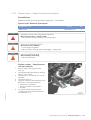
Transport
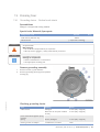
Crankshaft transport locking device
Crankshaft transportation lock – For
transport with flange-mounted generator
Safety regulations for startup and operation
Safety regulations for maintenance and
repair work
Fire prevention and environmental
protection, fluids and lubricants, auxiliary
materials
Standards for safety notices in the text
5 Maintenance
5
6
7
8
10
12
13
7 Task Description
7.1 Engine
16
18
19
20
21
3 Technical Data
3.1 12/16 V 4000 C13/13R/13L engine data:
Application group 5A, optimized fuel
consumption
3.2 12/16 V 4000 C13/13R/13L engine data:
Application group 5A, optimized exhaust
emissions (EPA Stage 2)
3.3 12/16 V 4000 C23/23R engine data:
Application group 5B, optimized fuel
consumption
3.4 12/16 V 4000 C23/23R engine data:
Application group 5B, optimized exhaust
emissions (EPA Stage 2)
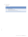
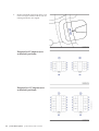
3.5 Firing order
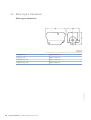
3.6 Main engine dimensions
32
39
DCL-ID: 0000013811 - 005
7.2 Cylinder Liner
7.2.1 Cylinder liner – Endoscopic examination
7.2.2 Instructions and comments on endoscopic and
visual examination of cylinder liners
7.3 Crankcase Breather
7.3.1 Crankcase breather – Oil separator element
replacement, diaphragm check and
replacement
7.4.1 Grounding device – Carbon brush check
7.4.2 Grounding device – Carbon brush replacement
7.5 Valve Drive
7.5.1 Valve gear – Lubrication
7.5.2 Valve clearance – Check and adjustment
7.5.3 Cylinder head cover – Removal and
installation
7.6 Injection Pump / HP Pump
7.6.1 HP pump – Filling with engine oil
43
47
48
7.7 Injection Valve / Injector
7.7.1 Injector – Replacement
7.7.2 Injector – Removal and installation
7.8 Fuel System
7.8.1 Fuel system – Venting
4 Operation
4.1 Preparations for recommissioning the
engine after extended out-of-service periods
(>3 months)
4.2 Putting the engine into operation after
scheduled out-of-service-period
4.3 Starting the engine in manual mode
4.4 Stopping the engine in manual mode
4.5 After shutting down the engine
4.6 Plant cleaning
7.1.1 Cranking engine manually
7.1.2 Engine – Barring with starting system
7.4 Running Gear
25
7.9 Fuel Filter
49
50
51
52
53
54
55
6 Troubleshooting
6.1 Troubleshooting
6.2 Fault messages of the engine governor
ADEC (ECU 7) for series 4000 C&I engines
2 General Information
2.1 Engine side and cylinder designations
2.2 Engine layout
2.3 Sensors and actuators – Overview
5.1 Maintenance task reference table [QL1]
7.9.1 Fuel filter – Replacement
7.9.2 Draining fuel prefilter
7.9.3 Fuel prefilter – Draining
7.10 Charge-Air Cooling
7.10.1 Intercooler – Checking condensate drain for
coolant discharge and obstructions
7.11 Air Intake
7.11.1 Service indicator – Signal ring position check
7.12 Starting Equipment
56
59
78
78
80
81
81
83
85
85
87
87
89
90
90
91
95
96
96
97
97
98
103
103
104
104
105
106
107
107
108
108
109
M015695/03E 2013-03 | Table of Contents | 3