1
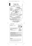
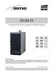
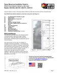
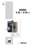
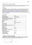
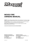
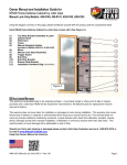
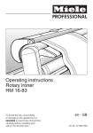
CX Operation and Installation Manual Applies to the: CX 12, CXC 12 and CXF 12 CX Manual Version 1.2, June 2015 Table of Contents 1 Welcome............................................................................................................................2 1.1 Structure of the wood burner .....................................................................................2 1.2 Packaging .................................................................................................................2 1.3 Assembly of the wood burner ....................................................................................2 1.4 Technical Specifications.............................................................................................3 1.5 Connections at the back of the stove.........................................................................3 1.6 Common Details ........................................................................................................4 2 Installation, clearances and hearth....................................................................................4 2.1 Installation..................................................................................................................4 2.2 Hearth........................................................................................................................5 2.3 The Chimney..............................................................................................................5 2.4 Connection of the heating system .............................................................................5 2.5 Connection of the over heat safety valve ..................................................................7 2.5.1 Testing the safety heat exchange .......................................................................7 2.6 Commissioning...........................................................................................................8 2.6.1 General information............................................................................................8 2.6.2 Physical checks..................................................................................................9 2.6.3 Smoke test for chimney soundness....................................................................9 2.6.4 Smoke evacuation test......................................................................................10 2.6.5 Lighting the appliance.......................................................................................10 2.6.6 Handover..........................................................................................................10 3 User operation.................................................................................................................12 3.1 Operation notes .......................................................................................................12 3.1.1 When used on a boat, never:............................................................................13 3.2 Initial heating up ......................................................................................................13 3.3 Normal operation......................................................................................................14 3.4 Safe storage of fuel..................................................................................................15 3.5 Actions in case of fume emission.............................................................................15 3.6 Actions in case of a chimney fire .............................................................................15 3.7 Advice on fitting suitable alarms...............................................................................16 3.8 Performance ............................................................................................................16 4 Maintenance and Cleaning .............................................................................................16 5 Common fault finding.......................................................................................................17 Page 1 1 Welcome Dear Customers, We thank you for your confidence extended to us through the purchase of this wood burner. Please read this operating manual carefully in order to insure a safe and sensible handling of the burner. Thus, you may prevent potential damages in advance and achieve a faultless functioning of the burner for many years. This burner may only be operated in a suitable environment. E.g. the usage is prohibited in rooms where work is carried out with solvents, flammable adhesives or coating agents. The following materials are suitable for burning in this wood burner: wood and woodbriquettes with a residual humidity not exceeding 20%. Please take care that this level of humidity is not exceeded, as the burner may otherwise lose a considerable amount of its performance, and permanent damages may occur. 1.1 Structure of the wood burner This burner is composed of a welded boiler-steel. An ash grate is located on the furnace floor, with an ash container below. The combustion chamber cladding consists of refractory clay or cast-iron plates. In the chimney duct is a deflector plate which is essential for an optimized flow of the exhausts. The furnace door is equipped with an inspection window which is especially designed for the use with high temperatures. The combustion chamber is fed with both primary and secondary air intake. The primary air intake enters the chamber below the grate – and thus serves as a performance regulator. The secondary air intake is pre-heated and serves the combustion of residual gases, while ‘washing’ the interior inspection window in the combustion chamber, thus preventing the build-up of ash residue. 1.2 Packaging The wood burner is delivered on a wooden palette in an assembled condition. 1.3 Assembly of the wood burner In order to avoid damage due to transport as much as possible, the assembly should be conducted at its place of destination. Should the burner be installed on a floor made of easily flammable material, then a fire resistant base has to be used. When placing the burner, please ensure the sufficient strength of the floor, and that it is non-flammable. Ensure any cellophane wrapping that maybe around the fire bricks inside the firebox is removed prior to lighting the stove. Page 2 1.4 Technical Specifications CX12 CXC12 CXT12 Max heat output 12kW (10.8kW to water) 12kW (10.8kW to water) 12kW (10.8kW to water) Nominal heat output 10kW (9kW to water) 10kW (9kW to water) 10kW (9kW to water) Back of stove to centre of flue 150mm 150mm 150mm Dimensions H | W | D 885mm x 530mm x 485mm 1070mm x 520mm x 450mm 810mm x 520mm x 450mm Window size H | W 390mm x 280mm Usable firebox H | W | D 335mm x 340mm x 325mm 335mm x 340mm x 325mm 390mm x 280mm 390mm x 280mm 335mm x 340mm x 325mm Table 1 1.5 Connections at the back of the stove Table 2 Illustration 1 Page 3 1.6 Common Details Efficiency 82% Max operating pressure 2.5 bar Flue diameter 150mm Direct air spigot diameter 100mm Flow and return connections 1” BSPF Overheat safety coil connections ½” BSPM Thermostat port connection ½” BSPF Minimum chimney draw 10Pa CO 0.90% Flue gas temperature 275ºC Table 3 2 Installation, clearances and hearth The stove MUST be installed by a competent person or company qualified to install solid fuel appliances with a boiler (e.g. HETAS) in line with local Building Regulations such as Approved Document J for England and Wales. Failure to comply with this may result in void product warranties. Failure to comply with this manual and local building regulations may also result in fire or carbon monoxide poisoning; however, any installation does not guarantee against such occurrences in all circumstances. 2.1 Installation There should be no combustible fixtures or furniture other than the floor and it's covering within 1,000mm of the front of the appliance. If using a direct air supply pipe then additional space will be needed in the chamber. The supply of fresh air is absolutely essential to the burner installation. The air intake pipe diameter needs to be at least the size of the air intake connectors at the back of the appliance. If the pipe is longer than 1,000mm, or there are offsets, then the pipe diameter needs to be increased. Sufficient incoming air in the installation room for combustion must be observed! Building Regulation Approved Document Part J require that a fixed air supply from the outside should be installed into the room where the stove is sited for the combustion air (Refer to Part J, Section 2, Table 1: Air supply to solid fuel appliances). Forced-air ventilation systems, extractor hoods or similar appliances which are installed in the same area as the stove will result in an increased demand on the incoming air supply. In such cases, please ensure that there is sufficient air able to enter the area to supply the stove and other appliances. Page 4 Attention should also be paid to having room around the stove for any pipework, the load unit etc. Serviceable parts of the system should be sited with appropriate provision made for access. End users should be strongly recommended to fit a smoke alarm and be guided to fit a carbon monoxide alarm in accordance with BS 8511:2012 (Annex C.5) 2.2 Hearth The sub-base and hearth must be able to carry the full weight of the boiler stove. The stove should be positioned on or above a non-combustible hearth and the hearth should extend a minimum of 300mm in front of the stove door. If the stove is raised up and the hearth is to be at floor level then we recommend that you increase the depth of the hearth to ensure that any embers that accidentally fall from the stove land on the hearth and not the floor. Please refer to Building Regulations Approved Document J for more specific details 2.3 The Chimney The following chimney designs are possible: • Brick wall chimney: This should be lined with pumice liners (not clay liners) of the correct diameter and the starter block should be set on the slab. The stove is then connected to the starter block with an adjustable length of single skin flue. • Assembled steel insulated chimney: The hole in the chamber roof should be a good fit around the pipe using a fire stop plate. • Stainless steel flexible liner (suitable for solid fuel, either 316 or 904 grade liners): The liner should be insulated. The stove should connect to the appliance via a length of rigid flue at least 500mm long. The liner should be firmly fixed to the chimney wall with a bottom support bracket or, if that isn't possible, then every pipe connection, including the connection to the stove, should be secured with at least two stainless steel self-tapping screws. The flexible liner should be insulated. The chimney should be fitted with a cowl or appropriate chimney pot to prevent rain entry. 2.4 Connection of the heating system Installations should always be carried out by a competent person. Please ensure that the heating system is thoroughly cleansed before connecting the boiler. Failure to do so could invalidate the warranty. NEVER operate the burner without connection to the heating system, as this may lead to irreparable damage to the water container of the burner. BS EN 12828 and BS EN 14336 specify requirements and give recommendations on good practice involved in the general planning, designing, installation and commissioning of forced circulation hot water central heating systems, and should be used where appropriate. The intended heating system can be laid out as an open or closed heating system. In any Page 5 case a sufficient overheating safeguard at the burner needs to be secured. If installed on a closed (pressurised) system, a pressure relief valve should be installed in the water circuit as close as practicable to the appliance and in a position where it would vent safely, along with an over heat safety valve (see section 2.5). If installed on an open vented system, the feed and expansion tank must be manufactured to BS 4215, and be designed to withstand the 500-hour boil test without leaking or collapsing. It should be installed as high as possible, in the highest part of the circuit and as near as possible to the boiler. A means of dissipating heat, e.g. a radiator fed by gravity, should be provided so that heat can be dissipated in cases where the pump fails or is not switched on and the appliance continues to produce heat. The water in the central heating system should contain suitable antifreeze to give frost protection. After a period of inactivity, on no account should the appliance be lit until it is ensured that there is a free flow of water through the central heating and hot water systems. The use of a return-flow-elevation or a three-way-valve (such as an LK 810 ThermoMat W Eco load unit) with an adjusted minimum temperature of 60°C is essential to ensure the stove burns cleanly and efficiently. The maximum operating temperature is 90°C. The maximum operating pressure may not exceed 1.5 bar. At the lowest points of the heating system an outlet valve needs to be installed. Illustration 2 Page 6 Illustration 2 is a suggested typical plumbing schematic showing the boiler stove connected to a thermal store. The positioning of the pipes for the heat leak radiator around the load unit is very important. In the LK 810 ThermoMat range, the gravity circuit flap grub screw should be removed to allow circulation around the heat leak radiator in the event of power failure. 2.5 Connection of the over heat safety valve The burner is fitted with a safety heat exchange coil (Connection no. 5 6 on illustration 1) which in the case of overheating, facilitates an easy and safe reduction of excess heat. The safety heat exchange consists of a copper coil in the inside of the water jacket. During the installation of the burner this copper coil needs to be connected via the connections on the top with a cold water connection and a waste water connection. The regulation of the cold water intake needs to be secured via a thermal safety valve (such as the Watts STS Thermal safety drain valve). The sensing element of the thermal drainage safety mechanism needs to be connected to the destined opening at the burner. The Installation of the thermal safety valve has to be executed by an authorised and competent company. The pipe pressure of the connected cold water has to be at least 2 bar and may not exceed 4.5 bar. Ensure a minimum passage of 20 l/min. A water filter needs to be installed in front of the valve intake in accordance with EN 13443. The sensing element of the thermal safety valve may need to be installed with an extension (½” x 40 mm [Connection no. 3 on illustration 1]). Please have the performance reliability of the safety heat exchange tested annually by an authorised and competent company. 2.5.1 Testing the safety heat exchange Test the safety heat exchange by temporarily overheating the burner to a boiler temperature >97°C. Where this is not possible, conduct the following alternative check: 1. 2. 3. 4. Remove the thermostat of the thermal safety valve sensing element from the burner Dip the thermostat in a container with water Bring the water in the container to the boil by heating The valve should now allow the inlet of cold water into the coil in the boiler Risk of injury due to hot water. If this check fails (the thermal safety valve does not open or does not close sufficiently later), The sensing element must be exchanged. Attention! It is not permissible to conduct any manipulation of the thermal safety valve and the safety heat exchange coil. Page 7 We recommend having a service check conducted by a competent company prior to the heating season. Where the burner is used only temporarily and where unfavourable winds or climatic conditions are present, greater care during initial operation is essential. After a prolonged period without firing up the burner, a check of the openness of the flue ways is necessary. During operation the surfaces of the burner are very hot; therefore please use protective gloves when handling the device. Supervise small children when they are present in the room where the burner is installed. Only original replacement parts and accessories may be used for the burner. 2.6 Commissioning The appliance and chimney installation should be tested by a competent person before final handover to the user or client to ensure that it is safe, fit for use and capable of providing the expected performance and service, in accordance with the method stated below. The tests and checks given in 2.6.1, 2.6.2 and 2.6.3 should be carried out before the appliance is lit for the first time. 2.6.1 General information Stove purchased from Telephone number Stove installed by Telephone number CPS registration with (e.g. HETAS) CPS registration number Installation date DAY / MONTH / YEAR Stove model Serial number Page 8 2.6.2 Physical checks Please tick when complete The installation is in accordance with the design, including material specification, flue length and diameter; These installation instructions have been followed; There is no damage to any components; Joints between the appliance and chimney and within the chimney system are secure and in good condition; The separation of components from combustible materials conforms to this code of practice; The appliance and chimney can be fully cleaned, once the installation is complete; Components for weatherproofing are installed correctly. CO Alarm fitted and tested 2.6.3 Smoke test for chimney soundness Please tick when complete It should be ensured that the chimney is complete and any removable/hinged section is in the operating position and secured in place according to the user instructions. Before commencing the test, the flue should be warmed for at least 10 minutes by a gas blow-lamp or similar placed on the grate, ensuring that the ash-pit cover and any air inlet into the stove are closed, but that the fire doors are left open to provide oxygen to the stove. Any cleaning or inspection opening in the flue should be closed and sealed. Once the flue is warm, a smoke pellet should be lit and placed on the grate, the fire doors closed and any additional air entry opening into the stove sealed off. When the smoke reaches the top of the flue, the chimney should be capped and sealed using an inflatable bladder, closed cell sponge bung, plastic bag and tape or other similar method. The whole length of the connecting flue pipe and chimney should be examined for smoke leakage from joints. If smoke leakage is evident, checks should be made to ensure the correct fitting of components before a further test is carried out to confirm the leakage has been corrected. Page 9 If this test is done without warming the flue, the cold flue might not seal because thermal expansion might have been taken into account in design or construction. 2.6.4 Smoke evacuation test Please tick when complete After completing the smoke test for chimney soundness, while the flue is still warm (if carried out at any other time the flue should be warmed for ten minutes first) this test should be carried out to ensure all the smoke is drawn up the flue to atmosphere. All doors, windows and closable vents in the room/cabin should be closed and any extraction fans should be switched on. A smoke pellet, with a burn time of approximately 60 seconds or more should be lit and placed on the appliance grate. The fire door(s) of the appliance should be closed and the primary air vent and flue damper fully opened. Smoke should be checked for entering the room and after 30 seconds, a check should be made that smoke is issuing from the chimney outlet and from no other point outside the room. If any smoke is emitted into the room from any point on the installation, the appliance should not be allowed to be lit until the fault has been corrected and the test repeated and passed. 2.6.5 Lighting the appliance Once all commissioning checks are complete, the appliance should then be lit for the first time by the competent person, given gradual initial firing, and then run at nominal output for 30 minutes before being turned to a low output setting for 30 minutes to ensure the stove enamel has been 'cured' prior to the first use by the end user. 2.6.6 Handover At handover all user instructions should be given to the user and an explanation of the appliance operation and safety issues should be given. Page 10 At handover an explanation of the correct removal, relocation, and any sealing of the removable/hinged section of the chimney should be given and all safety issues explained. Commissioning engineer's signature* *By signing this you confirm that all commissioning checks above have passed, and that operation and maintenance of the appliance have been explained to the customer in full in line with this user manual Customer signature Date DAY / MONTH / YEAR Page 11 3 User operation Running your own boiler stove can be an enjoyable process and you also get a very clear understanding of how much fuel your house is using to provide heating and hot water. Pay good attention to making sure that your wood is dry (moisture content of 20% or below) and well stocked, keep your chimney well swept, and burn the appropriate amount of wood in the stove to meet your heating and hot water needs. How much wood you should load the stove with, and how often you should reload it, partly depends on how much heat you need (how cold it is outside and how much domestic hot water you are using) and, of course, on the type and quality of wood you are burning. During the first few weeks of using your stove you will learn to use it in the way which suits your needs and circumstances best. Paying attention to outside and inside temperatures, as well as how different types and volumes of wood effect the heat output of the stove, will help. A boiler stove is not like an automatic gas boiler - you need to pay more attention to it, monitoring the stove so that you can regulate the output, load more wood, or let it go out as needed. If you have the stove connected to an accumulator tank then you should also pay attention to the temperatures in the tank during the burn cycle. You will no doubt develop your own tricks for using the stove over time. For example there are many different ways of building a fire and no one way is the only right way. If in doubt then please do ask your supplier and/or installer. We wish you many years of good use from your Woodfire stove. 3.1 Operation notes The burner may only be operated in accordance with this operating manual. It may only be operated with suitable fuel. When topping up, the fuels may not touch the inspection window of the furnace door. Please place the wood into the firebox rather than throwing it in as you could break the glass. Do not overfill the firebox. 50% full is the maximum you should aim for. Except when topping up, the furnace door must remain closed. Do not leave the stove running unattended. The exterior walls of the burner are hot during operation. For a safe handling of the burner a protective glove is to be worn. Children may not operate the burner! Use only the recommended fuels. Typically these would be either well-seasoned wood logs or smokeless fuels approved by the appliance manufacturer. Never use petroleum coke, barbecue fuel or waste materials. Never use liquid fuels. It is to be insured that the burner is not overloaded. In the case of overloading the air intake is to be restricted. No easily flammable materials may be stored on top or in the vicinity of the burner. Page 12 Do not place or hang any combustible material, such as towels or clothing, on the hearth or above the appliance. Ensure that any combustible items, such as soft furnishings, curtains, furniture, pictures, calendars, posters and ornaments, are at a minimum 1,000mm safe distance from the appliance and cannot fall, slide or swing nearer to the appliance or flue pipe. Any signs of heat damage or combustible material, e.g. charring, singeing or seepage of liquid (lignin), or of suspicious smells in the vicinity of the appliance or flue pipe, should be investigated immediately. The appliance should not be used until the cause is identified and rectified. Oil or gas lamps should not be located above the appliance, or within 1,000mm of the appliance or in a position where fuel spillage from the lamp, either when in position or if dislodged, could hit any surface of the stove. Do not use the appliance if any part of the casing, flue pipe or door glass is cracked, the flue or door seals are leaking, the internal fire-bricks are in poor condition, if it has missing parts or it has been modified. Never carry out any unauthorised modification of the appliance. Consider a fire guard manufactured to BS 8423. Do not light the appliance if there is any possibility that any part of the water system is empty or frozen. 3.1.1 When used on a boat, never: • • • • leave the craft unattended, or travel through tunnels, when the solid fuel appliance is in use without checking that the appliance has not been over-fuelled and ensuring that the controls are appropriately set to prevent over-firing Operate the appliance the appliance with any door open, except for refuelling and removal of ashes, as this may over-fire the appliance, with consequential damage to the appliance and danger of boat fire Block or restrict the ventilators to the cabin Fill any petrol tank on or near the craft when a solid fuel appliance is in use 3.2 Initial heating up When new, there can be odours caused by burnt paint and varnish from the unit. This gradually fades away after 7-8 hours continuous burning. During this period, ensure proper ventilation of the room otherwise the produced vapours in high concentration may cause risk to the health and/or can stain the walls of the room. 3.3 Normal operation Page 13 In order to obtain uniform heating the combustion air should be provided continuously through the regulator. Continuous air supply from outside must be ensured especially in case of small airspace and doors/windows of airtight closing. Remove ashes from previous usage. To access the ash draw, pull down from the top of the grill under the air control levers (shown in illustration 4), the drawer is behind, turn the lever and pull the drawer out towards you (beware the ash may still be hot even hours after the stove has gone out). Dispose of hot ash safely. Place dry, finger-breadth thick softwood kindling in the firebox, it is practical to arrange it in pyramid shape and put 3-4 kg of firewood on the top Fully open the primary and secondary air intake by pushing the levers under the door fully in (primary air is on the left shown in illustration 4, secondary air is on the right) Now ignite the softwood by using paper to set fire. You may use solid ignition aids for lighting up the paper. NEVER LEAVE THE STOVE UNATTENDED WITH THE DOOR(S) OPEN. The performance regulation is done using the operation of the primary air intake regulator Illustration 4 (Illustration 4). At an advanced stage of burning-down, the primary air intake regulator may be shut mostly. The regulation of the combustion is then for the main part regulated via the secondary air intake regulators (right hand lever). The optimum adjustment has to be determined by the user in accordance with local conditions. In order to prevent fumes entering the airspace, do not open the door(s) quickly. Apart from when the stove is first lit, or when it has been refuelled, make sure that there are good visible flames with no smoke when you look through the glass window. If there is smoke or smouldering this indicates that the air vent needs to be opened more, or there may be a problem with the fuel type, or with the chimney. Do not slumber burn the stove, or turn it down for the night: this will result in high levels of tar deposits in the chimney (leading to increased risk of chimney fire) and the window will blacken up. When you want to let the stove go out simply leave it to burn down, do not shut the air control. Page 14 3.4 Safe storage of fuel All solid fuel should be stored dry and away from sources of heat; wood logs should be stowed under cover with adequate ventilation provided. Under no circumstances should fuel be placed on the hearth, or near other sources of heat, e.g. for drying of wood logs Solid fuel should not be stored within 1,000mm of the appliance unless separated by a non-combustible partition. Flammable liquids, gas bottles, aerosols, etc. should be stored in a separate area wellaway from the appliance and not within the accommodation area. 3.5 Actions in case of fume emission Fume emission into the room or cabin is dangerous and could lead to carbon monoxide poisoning. If fume emission persists, the following immediate actions should be taken: • Open doors and windows to ventilate the room or cabin. • Let the fire out, or eject and safely dispose of fuel from the appliance. • Check the flue for blockage and clean if required. • Do not attempt to relight the fire until the cause of the fume emission has been identified and corrected. If necessary seek advice from a competent person. 3.6 Actions in case of a chimney fire Chimneys and exhaust tubes with a connected solid fuel burner need to be cleaned at least 6 times per year. During normal operation, but particularly when heating with damp fuels, sedimentation of soot and tar accumulates in the chimney. The neglect of the chimney maintenance and its cleaning increases the likelihood of the chimney catching fire. Should this occur, please proceed as follows: • Never attempt to extinguish fire with water! • Reduce the appliance-burning rate by closing all air controls (if safe to do so). • Move furniture and rugs away from the appliance and remove any nearby ornaments (if safe to do so). • Place a fire-guard or spark guard in front of the appliance (if safe to do so). • If necessary: ◦ raise the alarm; vacate the building/craft if possible and let occupants of any adjacent craft or buildings know; ◦ call the Fire Brigade; and ◦ determine best means for the Fire Brigade to gain access to the craft or building and wait for their arrival well away from the craft or building. Page 15 3.7 Advice on fitting suitable alarms At least one suitable and effective smoke alarm should be fitted in a suitable location. Alarms should be mounted on the ceiling at least 300mm from any walls and within 5 meters of the protected area. This may mean installing more than one alarm, and it is recommended to choose units that can be linked together. The smoke alarm should be capable of waking any occupants sleeping. The alarm should be tested with this in mind before the final fixing is made. The smoke alarm should be of the optical or photo electrical type since this is particularly sensitive to dense smoke such as produced from a smouldering fire. The smoke alarm should be fitted with an extra-long life battery and have a hush button to allow for temporary deactivation. This should be tested routinely. A carbon monoxide alarm certified to BS EN 50291 should also be fitted, and if on boats it should be suitable for marine use. 3.8 Performance The performance of the burner is dependent on the fuel used as well as the draught of the chimney. 4 Maintenance and Cleaning The stove may only be cleaned when cold. Although this stove does have an air-wash across the glass to reduce tar deposits, you will get slight blackening on the window over time as a result of the lower firebox temperatures in a boiler stove. Part of the regular care of your Woodfire stove will be cleaning the glass. This should always be done when the stove is cold. There are a number of stove glass cleaning products available but a damp rag dipped in a little ash will usually do the job very effectively. Ash can be taken out from the stove once it starts to build up to a level which restricts the volume of wood which can be burnt. The ash itself acts as an insulating layer at the base of the stove and in no way harms the operation of the stove. To access the ash draw, pull down from the top of the grill under the air control levers (shown in illustration 4), the drawer is behind, turn the lever and pull the drawer out towards you (beware the ash may still be hot even hours after the stove has gone out). Dispose of hot ash safely. Attention should also be applied to all ventilation, ensuring it is in good condition and free from any detritus, e.g. any grilles partially blocked by insects, plant growth or fluff. Never apply paint on the firebox that is not suitable for high temperature . Inspection of flue pipes is essential, and a chimney sweep registered with the National Association of Chimney Sweeps (www.nacs.org.uk) should be employed regularly for a clean and check. The flue should be swept at least at six-monthly intervals, or more Page 16 frequently where fouling of the flue is experienced. The upper baffle is a fire brick that can be removed to allow the brush head through, and should be replaced once the flue has been cleaned Chemical cleaners should not be used as a substitute for sweeping. Any damage or defect in the flue or appliance should be promptly repaired or replaced. Replacement parts should be those recommended by Woodfire, or compatible with the original part in compliance with BS 8511. 5 Common fault finding Please be aware that in the event of your stove not performing properly, you should always consult your installer first or a qualified professional. Below is a list of potential problems and possible causes: Problem Possible cause Kindling problems Burning does not start • • • • Fire gets choked • • Bad quality or wet wood Too thick wood log Insufficient primary air Cold flue pipe Insufficient draft Obstructed chimney or pipes, butterfly throttle is closed Burning problems Too slow fire progression • • • No ember layer produced Bad quality or wet wood Insufficient primary air Insufficient draft, low pressure • Too thick wood or log Improper placement of the wood Fire extinguishes • Too strong or too weak draught Too brisk flame – not possible to regulate • Too much combustion air Too small wood pieces • • Sooting Chimney fire • • Bad quality or wet wood Cold flue pipe Page 17 • • • Insufficient heating • • • Stove smoking • • • • • • • • Extensively glass window contaminated • • • Slow burning for longer period Too long chimney section in cold zone Always caused by extensive sooting of flue pipe Fresh or too wet wood Too strong air flow Improper firebox installation Wet or soft wood Flue pipe obstructed Flue damper is closed Operating of closed firebox with door in open position Contaminated flame baffle and/or connecting pipes Chimney not according to requirement Effect of the wind to the top opening Insufficient air exchange in the room or the mechanical ventilation interferes (such as kitchen odour extractor) Bad quality or wet wood Not suitable or prohibited fuel Excessive slow burning Page 18 www.woodfirestoves.co.uk