1
49TPTQ-104C ♦ 48TQuantum Platform
47TIEC 60870-5-104 Client
Module Configuration
12TUser Manual
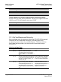
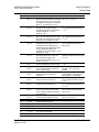
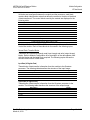
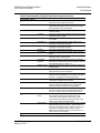
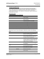
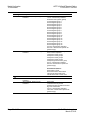
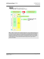
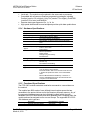
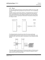
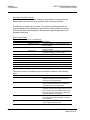
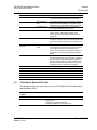
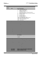
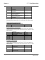
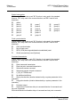
As blocks are transferred between the module and the processor, each block
contains block identification codes that define the content or function of the block
of data transferred. The control blocks used by the module are displayed in the
following table.
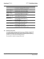
Descriptions
Status Data
Client X Status Data
User Constructed Command
Command Control Block (Add command to Command List Queue)
Event Messages
Command List Error data
Set PLC time using module’s time
Set module’s time using PLC time
Warm Boot Request from PLC (Block contains no data)
Cold Boot Request from PLC (Block contains no data)
Block Range
9250
9251
9901
9902
9903
9950
9970
9971
9998
9999
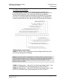
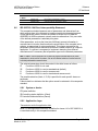
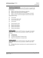
Block identification codes 9901 to 9999 are used for special control blocks to
control the module. Each of these blocks is discussed in the following topics.
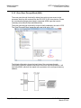
Normal Data Transfer Blocks
These data are transferred through read (input image) and write (output image)
blocks. Refer to Module Configuration for a description of the data objects used
with the blocks and the ladder logic required. The following topics discuss the
structure and function of each block.
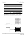
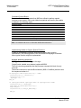
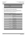
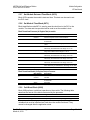
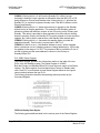
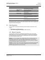
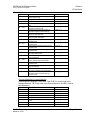
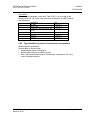
Input Data (3x Register Data)
These blocks of data transfer information from the module to the Quantum
processor. The following table describes the structure of the input image.
Offset
0
1
2 to 63
64 to n
Description
Sequence Counter
Block ID
Command Response Data
Read Data
Length
1
1
62
0 to 3999
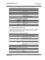
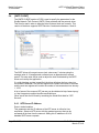
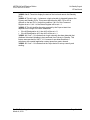
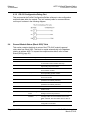
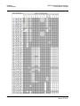
Output Data (4x Register Data)
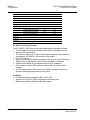
These blocks of data transfer information from the Quantum processor to the
module. The following table describes the structure of the output image.
Offset
0
1
2 to 63
64 to n
Description
Sequence Counter
Block ID
Command Data
Write Data
ProSoft Technology, Inc.
March 4, 2013
Length
1
1
62
0 to 3999
Page 49 of 136