1
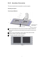
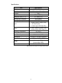
8.0” Rack-mountable TFT LCD MONITOR User Manual Part Number 82-12455 Version: V0.08c Notice: Federal Communications Commission (FCC) This equipment has been tested and found to comply with the limitations for a Class B digital device, pursuant to Part 15 of the FCC Rules. These limits are designed to provide reasonable protection against harmful interference in a residential installation. This equipment generates, uses, and can radiate radio frequency energy and, if not installed and used in accordance with the instructions, may cause harmful interference to radio communications. However, there is no guarantee that interference will not occur in a particular installation. If this equipment does cause harmful interference to radio or television reception, which can be determined by turning the equipment off and on, the user is encouraged to try to correct the interference by one or more of the following measures: • Re-orient or relocate the receiving antenna. • Increase the separation between the equipment and the receiver. • Connect the equipment into an outlet on a circuit different from that to which the receiver is connected. • Consult the dealer, or an experienced radio/TV technician for help. Safety Precautions Please read this User’s Manual carefully. Please keep and follow all instructions. Please heed all warnings. Please use only the power adapter that came with the equipment. Unauthorized adapters or accessories from other sources may damage the equipment. Before turning on the equipment, please make sure that all the peripheral devices are installed correctly. Keep the equipment away from liquids while in use. Clean only with dry cloth. Keep the equipment away from direct sunlight or heat sources. Do not block any ventilation openings. Install in accordance with the manufacturer’s instructions. Please mount the system in a stable fashion on a desk or in a rack to avoid injury to personnel or the system. Safety Information (cont’d) Never place any object on the power cord nor route the power cord near foot traffic. Do not overload electrical power outlets; this can result in fire or electric shock. Never repair the equipment by yourself. The user may be exposed to 2 hazard if the cover is removed. Unplug the power cord in case of the following situations: The power cord is damaged. Liquids are splashed on the system. The system is dropped onto the ground or the chassis is damaged. If the system is damaged, please package it carefully for repair. Always use the polarized, grounding-type plug supplied with the unit. Using a non-grounded plug can cause damage to the unit, especially in lightening storms. Unplug this apparatus during lightning storms or when unused for long periods of time. Avoid plugging power cord into overloaded AC outlet. Serious equipment damage, or fire could result from over loading the circuit. Monitor should only be serviced by a trained technician, or the original manufacturer Disconnect the power from the monitor if any of the following situations occur: Power cord damaged Water/liquid splits on monitor The monitor is dropped, or the cabinet damaged Warranty Information A 1-year warranty against workmanship from the data of purchase is valid only if the monitor housing is unopened. If a problem is encountered under normal use, please contact Defender Security Customer Service at 1-800-543-4330. Warranty cannot be guaranteed if damage to the monitor is determined to be the result of misuse. Safety Warnings WARNING RISK OF ELECTRIC SHOCK DO NOT OPEN WARNING: To reduce the risk of electric shock, do not remove the front or back covers. No user-serviceable parts inside. Refer servicing to qualified service personnel only. The lightning flash with arrow-head The exclamation point within a triangle within a triangle is intended to inform is intended to tell the user that the user that parts inside the product important operating and servicing are a risk of electric shock. instructions are explained. 3 Part 1 Introduction........................................................ 5 Check the Contents of the Package.......................................... 5 Understand Each Part ................................................................ 5 Description of the Function Buttons ........................................ 7 Control Operation................................................................................... 7 OSD Menu ............................................................................................. 7 OSD Function Menu .............................................................................. 7 Part 2 Assembly of Accessories ................................. 8 Assembly Description ................................................................ 8 Connecting the Monitors ........................................................................ 8 Disassembly of the Support Stand......................................................... 9 Appendix.......................................................................... 9 Product Dimensions................................................................... 9 Specifications ........................................................................... 10 4 Part 1 Introduction This section describes the preparation before start up and the operation of the function buttons. • “Understand the contents of the package.” • “Understand each part.” • “Understand the operation of the functions.” Package Contents □ 8.0” TFT LCD Monitor x1 □ Power cord x1 □ User’s manual x1 Understand Each Part This section describes each part of the monitor. Overview of the Front Side of the Product 1 4 2 3 Description 1 Monitor 2 Speaker 3 Function Buttons 4 Speaker 5 Overview of the Rear Side of the Monitor 8 1 9 2 3 10 4 5 6 11 12 13 7 Description 1 Audio 1, input terminal for the right channel (AUDIO 1 R IN) 2 Audio 1, input terminal for the left channel (AUDIO 1 L IN) 3 Audio 2, input terminal for the right channel (AUDIO 2 R IN) 4 Audio 2, input terminal for the left channel (AUDIO 2 L IN) 5 Audio output terminal for the right channel (AUDIO R OUT) 6 Audio output terminal for the left channel (AUDIO L OUT) 7 Support stand 8 Video 1 input terminal (VIDEO 1 IN ) 9 Video 1 output terminal (VIDEO 1 OUT) 10 Video 2 input terminal (VIDEO 2 IN ) 11 Video 2 output terminal (VIDEO 2 OUT) 12 Y/C color separation signal input terminal (S-VIDEO IN) 13 Power input connector (DC IN) 6 Description of the Function Buttons Control Operation POWER ─ Power on/off switch SOURCE ─ Signal source switch MENU ─ On-screen display of menu/confirm operation UP ─ Move up/Increase (Turn the volume up ) DOWN ─ Move down/decrease(Turn the volume down) OSD Menu 1. LANGUAGE ─Language 2. CONTRAST ─Contrast 3. BRIGHTNESS ─Brightness 4. COLOR ─Color 5. TINT ─Tint 6. SHARPNESS ─Sharpness 7. RESET ─Reset 1. When the MENU button is pressed, the monitor will show the main menu. 2. Use the DOWN, UP buttons to move the cursor down/up. The currently selected item will be displayed in green text on a white background. After confirming that the desired item is selected, press the MENU button to enter the submenu for the selected item. OSD Function Menu 1. LANGUAGE 2. CONTRAST 3. BRIGHTNESS 4. COLOR 5. TINT There are 11 languages available: English, Chinese(traditional), Chinese(simplified), Japanese, French, Spanish, Italian, German, Portuguese, Russian, and Czech. Adjusts the contrast of the monitor. Adjusts the brightness of the monitor. Adjusts the color saturation of the monitor. Adjusts the color tint of the monitor (for NTSC systems). Adjusts the sharpness of the monitor. Reset to the default settings. 6. SHARPNESS 7. RECALL Note: VOLUME: there is no menu associated with the volume control; just press the DOWN and UP buttons to adjust the sound volume. 7 Part 2 Assembly of Accessories This section describes how to assemble two monitors together. Assembly Description Connecting the Monitors Rack mount bracket Screws for the rack mount bracket Rack mount bracket Rack mount bracket 1 Place the saw-shaped side of the rack mount bracket towards the BNC side for the monitor connection and then fasten the six screws for the rack mount brackets. 2 Install the rack mount brackets on the two sides of the monitor and then fasten two screws on each rack mount bracket. 3 The complete assembly is shown in Figure 1. Figure 1 8 Disassembly of the Support Stand 1 After removing the screws from the support stand, the support stand can be removed. Screws for the support stand Support stand Appendix Product Dimensions IN Video - I OUT R Audio IN-I L R IN Video - II OUT Audio IN-II L R Audio OUT S-Video IN DC 12V IN 9 L Specifications Item Specification LCD Monitor 8” TFT LCD Monitor Resolution 800mm(H) x 600mm(V) Contrast 500 Brightness 300cd/m2(MIN.) Response Time (Tr / Tf) 10 / 15ms(TYP.) Viewing Angle Left/Right 70o/70o(MIN.) Viewing Angle Up/Down 70o/70o(MIN.) 2 x BNC Inputs (1.0Vp-p 75Ω) Input 1 x S-Video Inputs 1 x Audio Input (RCA Jack R,L) 2 x BNC Outputs (2.0Vp-p 75Ω) 1 x Audio Output (RCA Jack R,L) Output 0oC~40oC Operating Temperature Storage Temperature -10oC~60oC Power Consumption DC 12V/ 1.5A; 18W Dimensions 192.2(W) x 174.8(H) x 28(D)mm Dimensions of the Inner Box 280(L) x 244(W) x 97(H) Weight Net weight:1000g Gross weight:1500g Optional Accessories Rack mount bracket Specifications are subject to change without notice. 10