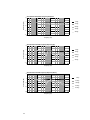
1
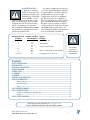
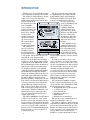
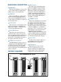
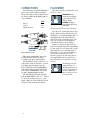
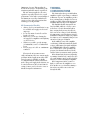
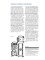
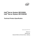
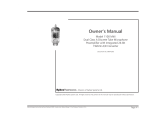
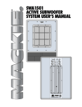
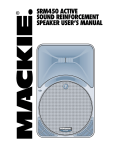
SA1232
3-WAY ACTIVE
SPEAKER SYSTEM
USER’S MANUAL
CAUTION
AVIS
RISK OF ELECTRIC SHOCK
DO NOT OPEN
RISQUE DE CHOC ELECTRIQUE
NE PAS OUVRIR
CAUTION: TO REDUCE THE RISK OF ELECTRIC SHOCK
DO NOT REMOVE COVER (OR BACK)
NO USER-SERVICEABLE PARTS INSIDE
REFER SERVICING TO QUALIFIED PERSONNEL
ATTENTION: POUR EVITER LES RISQUES DE CHOC
ELECTRIQUE, NE PAS ENLEVER LE COUVERCLE. AUCUN
ENTRETIEN DE PIECES INTERIEURES PAR L'USAGER. CONFIER
L'ENTRETIEN AU PERSONNEL QUALIFIE.
AVIS: POUR EVITER LES RISQUES D'INCENDIE OU
D'ELECTROCUTION, N'EXPOSEZ PAS CET ARTICLE
A LA PLUIE OU A L'HUMIDITE
The lightning flash with arrowhead symbol within an equilateral
triangle is intended to alert the user to the presence of uninsulated
"dangerous voltage" within the product's enclosure that may be
of sufficient magnitude to constitute a risk of electric shock to persons.
Le symbole éclair avec point de flèche à l'intérieur d'un triangle
équilatéral est utilisé pour alerter l'utilisateur de la présence à
l'intérieur du coffret de "voltage dangereux" non isolé d'ampleur
suffisante pour constituer un risque d'éléctrocution.
The exclamation point within an equilateral triangle is intended to
alert the user of the presence of important operating and maintenance
(servicing) instructions in the literature accompanying the appliance.
Le point d'exclamation à l'intérieur d'un triangle équilatéral est
employé pour alerter les utilisateurs de la présence d'instructions
importantes pour le fonctionnement et l'entretien (service) dans le
livret d'instruction accompagnant l'appareil.
SAFETY INSTRUCTIONS
1. Read Instructions — All the safety and operation instructions
should be read before this Mackie product is operated.
2. Retain Instructions — The safety and operating instructions
should be kept for future reference.
3. Heed Warnings — All warnings on this Mackie product and in
these operating instructions should be followed.
10. Power Cord Protection — Power supply cords should be routed
so that they are not likely to be walked upon or pinched by items
placed upon or against them, paying particular attention to cords at
plugs, convenience receptacles, and the point where they exit this
Mackie product.
11. Object and Liquid Entry — Care should be taken so that
objects do not fall into and liquids are not spilled into this Mackie
product.
12. Damage Requiring Service — This Mackie product should be
serviced only by qualified service personnel when:
A. The power-supply cord or the plug has been
damaged; or
B. Objects have fallen, or liquid has spilled into this
Mackie product; or
C. This Mackie product has been exposed to rain; or
D. This Mackie product does not appear to operate
normally or exhibits a marked change in performance;
or
E. This Mackie product has been dropped, or its chassis
damaged.
13. Servicing — The user should not attempt to service this
Mackie product beyond those means described in this operating
manual. All other servicing should be referred to the Mackie Service
Department.
14. To prevent electric shock, do not use this polarized plug with an
extension cord, receptacle, or other outlet unless the blades can be
fully inserted to prevent blade exposure.
4. Follow Instructions — All operating and other instructions
should be followed.
Pour prévenir les chocs électriques ne pas utiliser cette fiche
polariseé avec un prolongateur, un prise de courant ou une autre
sortie de courant, sauf si les lames peuvent être insérées à fond
sans laisser aucune pariie à découvert.
5. Water and Moisture — This Mackie product should not be used
near water – for example, near a bathtub, washbowl, kitchen sink,
laundry tub, in a wet basement, near a swimming pool, swamp, or
salivating St. Bernard dog, etc.
15. Grounding or Polarization — Precautions should be taken so
that the grounding or polarization means of this Mackie product is
not defeated.
6. Cleaning — Clean only with a dry cloth.
7. Ventilation — This Mackie product should be situated so that its
location or position does not interfere with its proper ventilation. For
example, the Component should not be situated on a bed, sofa,
rug, or similar surface that may block any ventilation openings, or
placed in a built-in installation such as a bookcase or cabinet that
may impede the flow of air through ventilation openings.
8. Heat — This Mackie product should be situated away from heat
sources such as radiators or other devices which produce heat.
WARNING: The heatsink may reach high temperatures during
standard use. To ensure proper operation, allow a minimum of 6
inches of clearance from the heatsink surface and adequate
ventilation.
9. Power Sources — This Mackie product should be connected to a
power supply only of the type described in these operation
instructions or as marked on this Mackie product.
16. Power Precaution — Unplug this Mackie product during
lightning storms or when unused for long periods of time. Note that
this Mackie product is not completely disconnected from the AC
mains service when the power switch is in the OFF position.
17. This apparatus does not exceed the Class A/Class B (whichever
is applicable) limits for radio noise emissions from digital apparatus
as set out in the radio interference regulations of the Canadian
Department of Communications.
ATTENTION —Le présent appareil numérique n’émet pas de
bruits radioélectriques dépassant las limites applicables aux
appareils numériques de class A/de class B (selon le cas) prescrites
dans le règlement sur le brouillage radioélectrique édicté par les
ministere des communications du Canada.
WARNING — To reduce the risk of fire or
electric shock, do not expose this appliance to
rain or moisture.
WARNING — The cabinet has no rigging
points and is not suitable for flying. Never
attempt to suspend the cabinet by its handles.
The SA 1232 should never be pole-mounted.
2
Lend Me Your Ears
Exposure to extremely
high noise levels may cause
permanent hearing loss. Individuals vary considerably
in susceptibility to noiseinduced hearing loss, but nearly everyone
will lose some hearing if exposed to sufficiently intense noise for a period of time.
The U.S. Government’s Occupational
Safety and Health Administration (OSHA)
has specified the permissible noise level exposures shown in this chart.
Duration Per Day
In Hours
8
6
4
3
2
1.5
1
0.5
0.25 or less
According to OSHA, any exposure in excess of these permissible limits could result
in some hearing loss. To ensure against potentially dangerous exposure to high
sound-pressure levels, it is recommended
that all persons exposed to equipment capable of producing these levels use hearing
protectors while this unit is in operation.
Ear plugs or protectors in the ear canals or
over the ears must be worn when operating
this amplification system in order to prevent a permanent hearing loss if exposure is
in excess of the limits set forth here.
Sound Level dBA, Typical
Slow Response Example
90
92
95
97
100
102
105
110
115
Duo in small club
Subway Train
Very loud classical music
Patrice screaming at Ron about deadlines
Loudest parts at a rock concert
The SA1232
can produce a
maximum SPL of
136 dB @ 1m
Contents
SAFETY INSTRUCTIONS .............................................................................................................2
INTRODUCTION ...........................................................................................................................4
REAR PANEL DESCRIPTION ........................................................................................................5
HOOKUP DIAGRAM .....................................................................................................................5
CONNECTIONS ............................................................................................................................6
PLACEMENT.................................................................................................................................6
AC POWER ...................................................................................................................................7
THERMAL CONSIDERATIONS .....................................................................................................8
SERVICE INFORMATION .............................................................................................................9
Warranty Service .............................................................................................................9
Troubleshooting ...............................................................................................................9
Repair ............................................................................................................................10
CARE AND MAINTENANCE .......................................................................................................10
SA1232 SPECIFICATIONS .........................................................................................................11
Architects and Engineers’ Specifications ......................................................................12
Graphs ...........................................................................................................................13
SA1232 LIMITED WARRANTY ...................................................................................................15
Don’t forget to visit our website at www.mackie.com
for more information about this and other Mackie products.
Part No. 0000431 Rev. B 4/03
© 2003 Mackie Designs Inc. All Rights Reserved.
3
INTRODUCTION
Thank you for choosing Mackie Designs’
The motor structure uses a high-grade
active sound reinforcement speaker systems. neodymium magnet providing extraordiThe SA1232 is a high-efficiency, extreme narily high BL (gauss) and performance.
output, active 3-way, wide dispersion,
The magnetic structure for both the highsound reinforcement speaker system. The
frequency and mid-frequency drivers
SA1232 benefits from
incorporate pure, high
the integration of 1300
grade, neodymium providwatts of amplifier
ing a higher gauss
power, complete active
capability, significant
control electronics, and
weight reduction, and
RCF Precision compohigher BL (force) in the
SA1232
nents. These elements
magnetic gap. This results
together form a
in better control of the
speaker system with
moving mass, and audio
103 dB of sensitivity
reproduction with lower
(@ 1 watt/1 meter).
distortion and excellent
The result is unpreclinearity.
edented output,
The amplifiers for the
resolution and clarity.
compression driver and
The SA1232 feamid-range driver incorpotures the same horn
rate a Class AB topology
assembly we introrenowned for its clarity
duced in the Mackie
and warmth, and for its
Designs SR1530 active
ability to produce the high3-way speaker. The horn is a one piece devoltage output required to generate extreme
sign with 90º x 40º dispersion that
SPL levels.
integrates both the mid-range and highBy using two 12-inch woofers, we profrequency sections. This provides seamless vide a cone surface area larger than a single
coupling between the MF and HF sections.
18-inch device, yet we are able to move it by
The 6-inch mid-range’s basket assembly is de- an order of magnitude faster. This results in
signed as part of the horn assembly and is
an extremely tight, deep bottom end, while
also designed to function as an optimized
efficiently reaching the mid-frequency
compression chamber, dramatically simplifycrossover point. The low-frequency ampliing the mid-range assembly. The SA1232
fier features an innovative Class G hybrid
features an “Optimized Wavefront” horn de- topology, which features two power supsign. Unlike typical mid/high horns where
plies for improved efficiency that delivers
the mid- and high-frequency horns are
1100 watts rms (continuous), and 1400
physically pointing to a different location in watts peak at 100 Hz.
front of the box, the SA1232’s high-frequency
The rear mounted amplifier assembly
section is positioned to fire down into the
features separate signal and AC power pansix-inch mid-range’s dispersion pattern.
els separated by a large aluminum heatsink.
This creates a focused, single wave front
The signal input panel contains:
with excellent phase and power response
• an input XLR and loop-through XLR
characteristics. With the resulting 90º x 40º
• a volume level control
dispersion pattern, the SA1232 provides
• Power On indicator
very open, natural sound reproduction at
• Signal Present indicator
extreme output levels.
• Limit indicator
The SA1232 Mid/High Section is designed
• Thermal protection indicator
to deliver over 136 dB of acoustic output.
The system accepts a standard line-level
In order to achieve this, the SA1232 incorpo- signal via an XLR input connector.
rates several state of the art advancements in
The SA1232 cabinet is constructed using
transducer technology, which were developed both multi-layered Baltic birch plywood and
over a two year period. The compression
pressure-injected structural resin caps. The
driver is a new 1.75-inch titanium diaphragm handles on each side are placed at the speaker’s
design. It features a 3-slot, low-distortion
center of gravity for easy carrying and setup.
geometry phase plug.
The top and bottom sections both have
handles for easy movement and relocation.
4
MAIN INPUT
POWER
PARALLEL
0dB
SIGNAL
LOOP OUT
-15
+5
ACTIVE SOUND REINFORCEMENT
SPEAKER SYSTEM
ON
WARNING:
CAUTION
THIS SURFACE MAY REACH HIGH TEMPERATURE DURING
STANDARD USE. TO ENSURE PROPER OPERATION ALLOW A MINIMUM OF 6 INS.
OF CLEARANCE FROM THIS SURFACE AND ADEQUATE VENTILATION. TO REDUCE
THE RISK OF ELECTRIC SHOCK DO NOT REMOVE THIS PANEL OR ANY ATTACHED
COMPONENT. NO OPERATOR SERVICEABLE PARTS INSIDE. REFER SERVICING TO
QUALIFIED PERSONNEL. TO REDUCE THE RISK OF FIRE OR ELECTRIC SHOCK, DO NOT
EXPOSE THIS APPLIANCE TO RAIN OR MOISTURE.
RISK OF ELECTRIC SHOCK
DO NOT OPEN
AVIS: RISQUE DE CHOC ELECTRIQUE — NE PAS OUVRIR
REPLACE WITH THE SAME TYPE FUSE AND RATING.
DISCONNECT SUPPLY CORD BEFORE CHANGING FUSE
SERIAL NUMBER
UTILISE UN FUSIBLE DE RECHANGE DE MÊME TYPE.
DEBRANCHER AVANT DE REMPLACER LE FUSIBLE
MANUFACTURING DATE
LIMIT
THERMAL
CONCEIVED AND DESIGNED BY MACKIE DESIGNS INC, WOODINVILLE, WA, USA
AND MACKIE EUROPE • MANUFACTURED IN ITALY • COPYRIGHT ©2001 •
THE FOLLOWING ARE TRADEMARKS OR REGISTERED TRADEMARKS OF MACKIE DESIGNS INC.:
"MACKIE", AND THE "RUNNING MAN" FIGURE • PATENT PENDING
REAR PANEL DESCRIPTION
MAIN INPUT
This is a female XLR-type connector that
accepts a balanced line-level signal from a
mixing console or other signal source.
LOOP OUT
This is a male XLR-type connector that
produces exactly the same signal that is
connected to the MAIN INPUT jack. Use it
to daisy-chain several SA1232s together off
the same signal source.
Level Control
This controls the overall signal level at the
input to the built-in power amplifiers. It
ranges from –15 dB to +5 dB of gain. The
center detent is 0 dB (unity gain).
Power ON Indicator
When the power switch is turned on,
and the linecord is connected to an active
AC power supply, this indicator lights green
to let you know that you’re ready to rock
and roll. The cool blue LED on the front of
the cabinet works in the same way.
SIGNAL Present Indicator
This LED illuminates whenever there is
a signal present at the MAIN INPUT connector on the rear panel. It senses the signal
just after the Level control, so if the Level
control is turned down, the SIGNAL Present
indicator turns off.
HOOKUP DIAGRAM
LIMIT Indicator
The SA1232 has a built-in limiter that
prevents the amplifier outputs from clipping or overdriving the transducers. The
LIMIT indicator lights when the limiter is
activated. It’s okay for the LIMIT indicator
to blink occasionally, but if it blinks frequently or lights continuously, turn down
the level control until the LIMIT indicator
only blinks occasionally.
THERMAL Indicator
There is also a thermal protection circuit
that monitors the internal temperature of
the amplifiers and heatsink. If the temperature should exceed a safe operating level,
this indicator lights and the signal is muted
to allow the amplifiers to cool. When the
temperature cools to a safe level once again,
the thermal protection circuit deactivates
and normal operation continues.
Note: Activation of the thermal protection
circuit is an indication that you should take
steps to avoid continued thermal problems.
See “Thermal Considerations” on page 8.
Power Switch
Use this switch to turn the SA1232 on
and off. Make sure the level control is
turned down before you turn it on.
AC Receptacle
This is where you connect the AC
linecord to provide AC power to the
SA1232’s built-in power amplifiers. Plug
the linecord into an AC socket properly
configured for your particular model.
DAISY-CHAINING MULTIPLE SA1232s
To Next
Speaker
To Next
Speaker
MAIN INPUT
POWER
-15
+5
LOOP OUT
-15
+5
0dB
0dB
SIGNAL
SA1232
ACTIVE SOUND REINFORCEMENT
SPEAKER SYSTEM
THERMAL
PARALLEL
PARALLEL
PARALLEL
LIMIT
CONCEIVED AND DESIGNED BY MACKIE DESIGNS INC, WOODINVILLE, WA, USA
AND MACKIE EUROPE • MANUFACTURED IN ITALY • COPYRIGHT ©2001 •
THE FOLLOWING ARE TRADEMARKS OR REGISTERED TRADEMARKS OF MACKIE DESIGNS INC.:
"MACKIE", AND THE "RUNNING MAN" FIGURE • PATENT PENDING
POWER
POWER
0dB
SIGNAL
SA1232
ACTIVE SOUND REINFORCEMENT
SPEAKER SYSTEM
MAIN INPUT
MAIN INPUT
POWER
0dB
LOOP OUT
LIMIT
LOOP OUT
SIGNAL
SA1232
-15
+5
ACTIVE SOUND REINFORCEMENT
SPEAKER SYSTEM
THERMAL
CONCEIVED AND DESIGNED BY MACKIE DESIGNS INC, WOODINVILLE, WA, USA
AND MACKIE EUROPE • MANUFACTURED IN ITALY • COPYRIGHT ©2001 •
THE FOLLOWING ARE TRADEMARKS OR REGISTERED TRADEMARKS OF MACKIE DESIGNS INC.:
"MACKIE", AND THE "RUNNING MAN" FIGURE • PATENT PENDING
PARALLEL
MAIN INPUT
LOOP OUT
LIMIT
Left
Line level
Output
SIGNAL
SA1232
-15
+5
ACTIVE SOUND REINFORCEMENT
SPEAKER SYSTEM
LIMIT
THERMAL
THERMAL
CONCEIVED AND DESIGNED BY MACKIE DESIGNS INC, WOODINVILLE, WA, USA
AND MACKIE EUROPE • MANUFACTURED IN ITALY • COPYRIGHT ©2001 •
THE FOLLOWING ARE TRADEMARKS OR REGISTERED TRADEMARKS OF MACKIE DESIGNS INC.:
"MACKIE", AND THE "RUNNING MAN" FIGURE • PATENT PENDING
CONCEIVED AND DESIGNED BY MACKIE DESIGNS INC, WOODINVILLE, WA, USA
AND MACKIE EUROPE • MANUFACTURED IN ITALY • COPYRIGHT ©2001 •
THE FOLLOWING ARE TRADEMARKS OR REGISTERED TRADEMARKS OF MACKIE DESIGNS INC.:
"MACKIE", AND THE "RUNNING MAN" FIGURE • PATENT PENDING
Right
Line level
Output
1202-VLZ PRO
Mixer or
Preamplifier
ON
WARNING:
CAUTION
THIS SURFACE MAY REACH HIGH TEMPERATURE DURING
STANDARD USE. TO ENSURE PROPER OPERATION ALLOW A MINIMUM OF 6 INS.
OF CLEARANCE FROM THIS SURFACE AND ADEQUATE VENTILATION. TO REDUCE
THE RISK OF ELECTRIC SHOCK DO NOT REMOVE THIS PANEL OR ANY ATTACHED
COMPONENT. NO OPERATOR SERVICEABLE PARTS INSIDE. REFER SERVICING TO
QUALIFIED PERSONNEL. TO REDUCE THE RISK OF FIRE OR ELECTRIC SHOCK, DO NOT
EXPOSE THIS APPLIANCE TO RAIN OR MOISTURE.
RISK OF ELECTRIC SHOCK
DO NOT OPEN
ON
WARNING: THIS SURFACE MAY REACH HIGH TEMPERATURE DURING
CAUTION
STANDARD USE. TO ENSURE PROPER OPERATION ALLOW A MINIMUM OF 6 INS.
OF CLEARANCE FROM THIS SURFACE AND ADEQUATE VENTILATION. TO REDUCE
THE RISK OF ELECTRIC SHOCK DO NOT REMOVE THIS PANEL OR ANY ATTACHED
COMPONENT. NO OPERATOR SERVICEABLE PARTS INSIDE. REFER SERVICING TO
QUALIFIED PERSONNEL. TO REDUCE THE RISK OF FIRE OR ELECTRIC SHOCK, DO NOT
EXPOSE THIS APPLIANCE TO RAIN OR MOISTURE.
RISK OF ELECTRIC SHOCK
DO NOT OPEN
AVIS: RISQUE DE CHOC ELECTRIQUE — NE PAS OUVRIR
REPLACE WITH THE SAME TYPE FUSE AND RATING.
DISCONNECT SUPPLY CORD BEFORE CHANGING FUSE
SERIAL NUMBER
UTILISE UN FUSIBLE DE RECHANGE DE MÊME TYPE.
DEBRANCHER AVANT DE REMPLACER LE FUSIBLE
MANUFACTURING DATE
SERIAL NUMBER
UTILISE UN FUSIBLE DE RECHANGE DE MÊME TYPE.
DEBRANCHER AVANT DE REMPLACER LE FUSIBLE
MANUFACTURING DATE
ON
ON
WARNING: THIS SURFACE MAY REACH HIGH TEMPERATURE DURING
CAUTION
STANDARD USE. TO ENSURE PROPER OPERATION ALLOW A MINIMUM OF 6 INS.
OF CLEARANCE FROM THIS SURFACE AND ADEQUATE VENTILATION. TO REDUCE
THE RISK OF ELECTRIC SHOCK DO NOT REMOVE THIS PANEL OR ANY ATTACHED
COMPONENT. NO OPERATOR SERVICEABLE PARTS INSIDE. REFER SERVICING TO
QUALIFIED PERSONNEL. TO REDUCE THE RISK OF FIRE OR ELECTRIC SHOCK, DO NOT
EXPOSE THIS APPLIANCE TO RAIN OR MOISTURE.
RISK OF ELECTRIC SHOCK
DO NOT OPEN
AVIS: RISQUE DE CHOC ELECTRIQUE — NE PAS OUVRIR
REPLACE WITH THE SAME TYPE FUSE AND RATING.
DISCONNECT SUPPLY CORD BEFORE CHANGING FUSE
WARNING: THIS SURFACE MAY REACH HIGH TEMPERATURE DURING
CAUTION
STANDARD USE. TO ENSURE PROPER OPERATION ALLOW A MINIMUM OF 6 INS.
OF CLEARANCE FROM THIS SURFACE AND ADEQUATE VENTILATION. TO REDUCE
THE RISK OF ELECTRIC SHOCK DO NOT REMOVE THIS PANEL OR ANY ATTACHED
COMPONENT. NO OPERATOR SERVICEABLE PARTS INSIDE. REFER SERVICING TO
QUALIFIED PERSONNEL. TO REDUCE THE RISK OF FIRE OR ELECTRIC SHOCK, DO NOT
EXPOSE THIS APPLIANCE TO RAIN OR MOISTURE.
RISK OF ELECTRIC SHOCK
DO NOT OPEN
AVIS: RISQUE DE CHOC ELECTRIQUE — NE PAS OUVRIR
AVIS: RISQUE DE CHOC ELECTRIQUE — NE PAS OUVRIR
REPLACE WITH THE SAME TYPE FUSE AND RATING.
DISCONNECT SUPPLY CORD BEFORE CHANGING FUSE
SERIAL NUMBER
UTILISE UN FUSIBLE DE RECHANGE DE MÊME TYPE.
DEBRANCHER AVANT DE REMPLACER LE FUSIBLE
MANUFACTURING DATE
REPLACE WITH THE SAME TYPE FUSE AND RATING.
DISCONNECT SUPPLY CORD BEFORE CHANGING FUSE
SERIAL NUMBER
UTILISE UN FUSIBLE DE RECHANGE DE MÊME TYPE.
DEBRANCHER AVANT DE REMPLACER LE FUSIBLE
MANUFACTURING DATE
5
CONNECTIONS
PLACEMENT
The SA1232 has one female XLR input
that accepts a balanced line-level signal.
When connecting a balanced signal, be sure
it’s wired per AES (Audio Engineering Society) standards:
The SA1232 speaker is designed to sit on
the floor or stage.
WARNING: The
cabinet has no rigging
points and is not suitable for rigging.
NEVER attempt to
suspend the SA1232 by
its handles.
The SA 1232 should never be pole-mounted.
Hot (+)
Cold (–)
Shield (Ground)
XLR
Pin 2
Pin 3
Pin 1
Balanced XLR Connectors
There is also a male XLR connector labeled LOOP OUT. This is also wired
according to the above AES standard.
The LOOP OUT connector allows you to
connect more than one SA1232 to your system. Simply plug the signal source (i.e.,
mixer output) into the first MAIN INPUT
jack, and patch that speaker’s LOOP OUT
jack to the next MAIN INPUT jack, and so
on, daisy-chaining multiple speakers.
The LOOP OUT jack is wired straight
from the MAIN INPUT connector — there is
no electronic circuitry between — so the
signal coming out of the LOOP OUT jack is
exactly the same as the signal going in.
6
You can create a horizontal array by placing the cabinets side-by-side. However, you
should have a good understanding of the relationship between the splay angle (the
angle between the facing sides of the cabinets), the on-axis power, and frequency
cancellation effects between cabinets.
When two cabinets are placed side-byside, the actual splay angle is 20º (determined
by a 10º angle on each cabinet side). As the
splay angle increases toward the angle of
horizontal coverage (90º for the SA1232),
the on-axis power decreases, but the
frequency response becomes smoother as
the comb-filtering effects (caused by the
interaction in the area of double-coverage)
decrease.
As with any powered
components, protect
them from moisture. If
you are setting them up
outdoors, make sure
they are under cover if
you expect rain.
AC POWER
Be sure the SA1232 is plugged into an
outlet that is able to supply the correct voltage specified for your model. If the voltage
should drop below 97% of the specified line
voltage, the built-in amplifiers will no
longer be able to supply rated power. (They
will continue to operate down to 80% of
the rated line voltage, but won’t reach full
power, resulting in lower headroom.)
Be sure the electrical service can supply
enough amperage for all the components
connected to it.
We recommend that a stiff (robust) supply of AC power be used because the
amplifiers place high current demands on
the AC line. The more power that is available on the line, the louder the speakers will
play and the more peak output power will
be available for cleaner, punchier bass. A
suspected problem of “poor bass performance” is often caused by a weak AC
supply to the amplifiers.
CAUTION: Never remove the ground pin on
the power cord of the
SA1232 or any other
component. This is very
dangerous.
SA1232 systems are available in 115V
and 230V AC configurations. Mackie Designs specifies a specific amount of
amperage service availability for individual
active cabinets. It is a good rule of thumb,
especially in countries using 115V AC
power, to know precisely the amount of
voltage/amperage service available to operate your active speaker systems safely and
to their full output capacity. We have provided specifications relative to minimum
amperage requirements that should be used
as a general guideline. Additionally, it is
necessary to comprehend the demands put
upon the AC service when running the
cabinets for prolonged periods of time at
maximum output levels. Depending on the
source material and level, cabinets running
on 115V AC can demand as much as 20
amps of peak amperage service. Depending
on the type of service available, this could
be beyond the capability of your AC system
and produce unwanted audible by-products.
115V
230V
Minimum
Amperage
15 Amps
10 Amps
Recommended
Service
20 Amps
16 Amps
AC sags, or lack of current can be audible. When running into this type of
problem, the anomaly generally encountered is similar to that of a processor
compressing the input signal very hard.
This is caused by the inability of the toroid
transformer to recharge the amplifier capacitors fast enough. As a result, the audio
performance gets very thin sounding and
you must lower the input level in order for
the system to recuperate. This is a very common problem for the pro-audio industry in
general. When you begin talking about amplifier systems that deliver high power
levels (more than 1,000 watts), the limitations of 115V AC service create problems.
Here are some basic calculations for
some high power amplifiers:
Amp
Output
Power
1000 watts
1500 watts
2000 watts
2500 watts
3000 watts
AC Service
115V
115V
115V
115V
115V
Required
Amps
8.7 Amps
13 Amps
17.4 Amps
21.7 Amps
26 Amps
If the signal reproduced were a full bandwidth sine wave, then the above data would
be true at full output with an absolutely flat
signal. An audio signal presents a distinct
problem when it comes to the reproduction
of transient signals found in the typical programs. For a very short time, the amplifier’s
power supply could require up to four times
the amperage as it tries to reproduce a 6 dB
peak. This is especially true of subwoofer
amplifier systems trying to reproduce frequencies below 50 Hz, which is the frequency
that AC power usually travels at. The
SA1232 amplifiers have extremely robust
toroidal transformers and use a large number of capacitors. Toroidal power supplies
have one huge advantage over other types
of supplies, which is their ability to provide
higher output beyond their nominal rating.
For a very short period of time, a well designed
2500 watt transformer can deliver up to
7
5000 watts of power. This provides the
headroom necessary to deal with the peak
transient signals that must be reproduced.
The AC current supplied to the active
speaker is especially critical to the overall
performance of the audio system. In light of
the limitations created by standard 115V
service, we have a list of suggestions that
will help you avoid problems.
AC Recommended Checklist
• Always check your installation/set up
for available AC supply rated circuit
amperage
• Locate the main electrical board for
breaker location
• Make sure you are not sharing the
AC supply for amplifiers with lighting
or other services
• Whenever possible, specify 20 amp
(15 minimum) service for individual
boxes
• Use 16 gauge AC cable as a minimum
standard.
The 230 volt AC systems are more
stable and run into far fewer current supply
problems. In fixed applications where 220230 volt service is available, we highly
recommend using the SA1232 in 230 volt
mode. The power supply in the SA1232 can
be switched between 115 volt and 230 volt
setting. Contact your local service center or
Mackie Designs for information.
8
THERMAL
CONSIDERATIONS
The SA1232 has three powerful built-in
amplifiers capable of producing a combined
1300 watts of power. As amplifiers produce
heat, it is important to dissipate the heat as
quickly as possible. This results in increased
reliability and longevity for the amplifier.
The amplifier module is mounted on a
large heatsink, which is cooled by convection where cool air is drawn through its
fins, carrying the heat away. In order for
this convection cooling to work efficiently,
it is important to provide adequate airspace
behind the loudspeaker. When you position
the SA1232, we recommend leaving at least
six inches of air space behind it.
In the unlikely event of the amplifier
overheating, a built-in thermal switch will
activate, which mutes the signal and lights
the THERMAL LED. When the amplifier
has cooled down to a safe operating temperature, the thermal switch resets itself,
and the SA1232 resumes normal operation.
If the thermal switch activates frequently,
try turning down the level control a notch or
two on the mixing console (or the back of the
SA1232) to avoid overheating the amplifier.
If the temperature in the room is too
high, it could cause the amplifier to overheat. In this case, you should try aiming a
fan at the rear panel to move more air
through the fins.
SERVICE INFORMATION
Warranty Service
If you think your loudspeaker has a
problem, please do everything you can to
confirm it before calling for service, including reading through the following
Troubleshooting section. Doing so might
save you from being deprived of your
Mackie loudspeaker.
Of all Mackie products returned for service (which is hardly any at all), many are
coded “CND” — Could Not Duplicate—
which usually means the problem lay somewhere else in the system. The following
troubleshooting tips may sound obvious,
but here are some things you can check:
Troubleshooting
No power
• Our favorite question: Is it plugged in?
Make sure the AC outlet is live (check
with a tester or lamp).
• Our next favorite question: Is the POWER
switch on? If not, try turning it on.
• Is the POWER LED on the rear panel
glowing green? If not, make sure the AC
outlet is live. If so, refer to “No sound”
below.
• The internal AC line fuse may be
blown. This is not a user serviceable
part. If you suspect the AC line fuse is
blown, please see the “Repair” section
next.
No sound
• Is the input LEVEL control for the
input source turned all the way down?
Verify that all the volume controls in the
system are properly adjusted.
• Is the signal source working (and
making union scale)? Make sure the
connecting cables are in good repair and
securely connected at both ends. Make
sure the output volume (gain) control
on the mixing console is turned up
sufficiently to drive the inputs of the
speaker.
• Make sure the mixer does not have a
Mute on or a Processor loop engaged. If
you find something like this, make sure
the volume/gain is turned down before
disengaging the offending switch.
• Is the THERMAL indicator lit red on
the rear panel? Make sure there is at
least six inches of free space behind the
SA1232.
Poor bass performance
• Check the polarity of the connections
between the mixer and the loudspeakers. You may have your positive and
negative connections reversed at one
end of one cable, causing one loudspeaker to be out-of-phase.
Poor sound
• Is it loud and distorted? Make sure that
you’re not overdriving a stage in the
signal chain. Verify that all level controls
are set properly.
• Is the input connector plugged completely into the jack? Be sure all
connections are secure. It’s a good idea
to periodically clean all electrical
connections with a non-lubricating
electrical contact cleaner.
Noise
• Make sure all connections to the active
loudspeakers are good and sound.
• Make sure none of the signal cables are
routed near AC cables, power transformers, or other EMI-inducing devices.
• Is there a light dimmer or other SCRbased device on the same AC circuit as
the SA1232? Use an AC line filter or
plug the SA1232 into a different AC
circuit.
Hum
• Try disconnecting the cable connected
to the MAIN INPUT jack. If the noise
disappears, it could be a “ground loop,”
rather than a problem with the SA1232.
Try some of the following troubleshooting ideas:
• Use balanced connections throughout
your system for the best noise rejection.
• Whenever possible, plug all the audio
equipment’s linecords into outlets which
share a common ground. The distance
between the outlets and the common
ground should be as short as possible.
9
Repair
Service for the SA1232 is available only
from one of our authorized domestic service stations or at the factory service center
located in Whitinsville, Massachusetts. Service outside the United States can be
obtained through local dealers or distributors.
If your SA1232 needs service, please follow these instructions:
1. Review the preceding troubleshooting
suggestions. Please.
2. Call Tech Support at 1-800-258-6883,
7am to 5pm PST, to explain the problem
in detail. They will ask you all sorts of
impertinent questions in the hope of
sorting out the problem. If it appears
that the SA1232 needs repair, request
an RA (Return Authorization) number.
Have your loudspeaker’s serial number
ready. You must have an RA number
before you can obtain service at the
factory or an authorized service center.
3. Keep this user’s manual. We don’t need
it to repair the loudspeaker.
4. Pack the loudspeaker in its original
packaging, including protective wrap,
endcaps, and box. This is very important. When you call for the RA number,
please let Tech Support know if you
need new packaging. Mackie is not
responsible for any damage that occurs
due to non-factory packaging.
5. Include a legible note stating your name,
shipping address (no P.O. boxes),
daytime phone number, RA number,
and a detailed description of the problem, including how we can duplicate it.
6. Write the RA number in BIG PRINT
on top of the box.
7. Ship the loudspeaker to us. We suggest
insurance for all forms of cartage. Ship
to this address:
Mackie/EAW Service
Building #11
One Main Street
Whitinsville, MA 01588
10
8. We’ll try to fix the loudspeaker in three
to five business days. Ask Tech Support
for current turnaround times when you
call for your RA number. The product
MUST be packaged in its original
packing box and have the RMA number
appear on the box. Once it is repaired,
we’ll ship it back to you the same way in
which it was received. This paragraph
does not necessarily apply to nonwarranty service.
CARE AND
MAINTENANCE
Your Mackie loudspeakers will provide many
years of reliable service if
you follow these guidelines:
• Avoid exposing the loudspeakers to
moisture. If they are set up outdoors, be
sure they are under cover if you expect
rain.
• Avoid exposure to extreme cold (below
freezing temperatures). If you must
operate the loudspeakers in a cold
environment, warm up the voice coils
slowly by sending a low-level signal
through them for about 15 minutes
prior to high-power operation.
• Use a slighty damp cloth with a mild
soap solution to clean the cabinets. Only
do this when the power is turned off.
Avoid getting moisture into any of the
openings of the cabinet, particularly
where the drivers are located.
SA1232 SPECIFICATIONS
Acoustic Performance
Low Frequency Section
–3 dB points
–10 dB points
Directivity Factor; Q (DI)
Number of Drivers
Woofer Size
Voice Coil Diameter
System Sensitivity1
Max SPL long-term
Max SPL Peak
Crossover
45 Hz-18 kHz
38 Hz-20 kHz
13.2 (11.2), averaged
2 kHz to 10 kHz
103 dB, 1W@1m
130 dB
136 dB
24 dB/octave @ 700 Hz
and 3000 Hz
Input/Output
Input
Loop-Through
(parallel w/input)
Level Control
Bal/Unbal Female XLR
Bal/Unbal Male XLR
Rotating knob (–15 to
+5 dB), center detent
@ 0 dB
Amplifiers
Total Amplifier Power
Diaphragm Material
Magnet Type
2
12"
3" with Inside/Outside
winding
Epoxy-reinforced
Cellulose
Ferrite
Construction Features
Basic Design
Material
Finish
Handles
Grille
Trapezoidal
13-ply Baltic birch, resin end caps
Wear-resistant textured black
PVC vinyl
One on each side,
One top, One Bottom
Perforated metal with weatherresistant coating
Line Input Power
Power Consumption
High Frequency
Type
Rated THD
1300 watts rms
continuous*
100 watts
Class AB
0.03%
Mid Frequency
Type
Rated THD
100 watts
Class AB
0.03%
Europe
230 VAC, 50 Hz
Recommended Amperage Service: 16 amps
Low Frequency
Type
Rated THD
1100 watts
Class G Hybrid
0.03%
Control System Functions
*Rated power is continuous rms wattage into
transducer’s minimum rated impedance @ 1 kHz
for HF and MF amps and 100 Hz for LF amps
High-Frequency Section
Diaphragm Size
Horn Exit Diameter
Phase Plug
Diaphragm Material
Magnet Type
1.75"
1"
3-Slot Optimized
Geometry
Damped titanium
Neodymium
Mid-Frequency Section
Diaphragm Size
Voice Coil Diameter
Phase Plug
Diaphragm Material
Magnet Type
6"
2"
Optimized Geometry
Epoxy-reinforced
Cellulose
Neodymium
US
120 VAC, 60 Hz
Recommended Amperage Service: 20 amps
AC Connector
3-pin IEC 250 VAC
Electronic Crossover
Phase Alignment
Time Correction
Equalization
Parametric Equalization
Safety Features
Protection
Low Frequency Dynamic Bass
Protection, RMS Limiting, Power
Supply and Amplifier Thermal
Protection
Display LEDs
Power ON, Signal Present, Limit,
Thermal (Cool Down Auto Reset)
Physical
Height
Front Width
Back Width
Depth
Weight
Mounting Methods
Mid/High Horn Design
Horizontal Coverage (–6 dB)
Vertical Coverage (–6 dB)
Type
Design Feature
450 W long term with
IEC pink noise and
limiter on
90º 1 kHz to 10 kHz avg.
40º 1 kHz to 10 kHz avg.
Constant Directivity
Optimized Wavefront
High/Mid Integration
1
50.0 in/127.0 cm
19.1 in/48.5 cm
13.9 in/35.3 cm
18.1 in/46.0 cm
132 lb/60 kg
Floor mount only.
The SR1530 should
never be pole-mounted.
The cabinet has no rigging points and is not
suitable for flying.
Never attempt to suspend the cabinet by
its handles.
Measured on-axis in the far field, referenced back to 1 watt rms from maxi-
mum power and to 1 meter distance using the inverse square law.
11
Architects and Engineers’ Specifications
The active three-way, full-range loudspeaker system shall incorporate two
12-inch low-frequency (LF) transducers, a
6-inch horn loaded mid-frequency (MF)
transducer, and a 1-inch exit, 1.75-inch
titanium dome compression driver highfrequency (HF) transducer. The LF drivers
shall be mounted in a vented enclosure
tuned for optimum low-frequency response.
The MF and HF transducers shall be loaded
on a symmetrical constant-directivity horn
assembly designed for wide dispersion.
The system shall have a nominal coverage
pattern of 90° (horizontal) x 40° (vertical).
System frequency response shall vary no
more than ± 3 dB from 45 Hz to 18 kHz
measured on axis. The loudspeaker shall incorporate a Class G low-frequency amplifier
capable of delivering 1100 watts rms over a
frequency range of 20 Hz–700 Hz. The system
shall incorporate two Class AB 100 watt
rms amplifiers specifically designed to
power the MF and HF drivers over the range
of 700 Hz–3000 Hz and 3000 Hz–20 kHz
respectively. The amplifiers shall be mounted
on an aluminum heat sink, which shall be
mounted on the rear of the speaker system,
and shall be convection cooled.
13.9 in
35.3 cm
19.1 in
48.5 cm
18.1 in
46.0 cm
Dimensions
19.1 in
48.5 cm
The rear mounted amplifier assembly
shall comprise separate signal and AC power
panels separated by a large aluminum heat
sink. The signal input panel shall contain
an input and loop-through XLR, a volume
level control, and four status LEDs for Power
ON, Signal Present, Limit, and Thermal
functions. The system shall accept a standard line-level signal via the XLR input
connector. The power switch and IEC AC
connector shall be located on the power panel.
Thermal protection shall be provided by
a thermal sensor mounted on the heat sink,
which monitors the heat sink temperature
and triggers the thermal protection circuit
should the temperature exceed 158° F
(70° C). The Thermal LED shall light and
the input signal shall be muted until the
heat sink cools to a safe operating level, at
which point the thermal protection circuit
auto-resets and normal operation resumes.
Overload protection shall be provided by
a limiter circuit, which monitors the lowfrequency amplifier output and reduces the
input level to the amplifier should the amplifier output begin to clip.
The loudspeaker enclosure shall have a
trapezoidal shape and shall incorporate two
side handles, one on each side, and a top
and bottom relocation handle. The enclosure shall be constructed of a combination
multi-ply wood and high-pressure injected
structural resin, with a black PVC vinyl finish. The front of the loudspeaker shall be
covered with a powder coated, weatherresistant perforated steel grille.
The active three-way full-range loudspeaker system shall be a Mackie Designs
SA1232.
Disclaimer
50.0 in
127 cm
Since we are always striving to make our products better by incorporating new and improved
materials, components, and manufacturing methods,
we reserve the right to change these specifications at
any time without notice.
“Mackie” and the “Running Man” figure are trademarks or registered trademarks of Mackie Designs Inc.
All other brand names mentioned are trademarks or registered trademarks of their respective
holders, and are hereby acknowledged.
12
18.1 in
46.0 cm
©2003 Mackie Designs Inc. All Rights Reserved.
Graphs
SA1232 Frequency Response On-Axis
SPL, 100 dB @ 1kHz (ref.)
110
100
90
80
70
20
100
1000
10000
20000
10000
20000
Frequency (Hz)
SA1232 Beamwidth vs. Frequency
–6 dB Beamwidth (degrees)
360
300
240
180
Vert BW
120
Horz BW
60
20
100
1000
Frequency (Hz)
100
10
10
0
20
100
1000
10000
Directivity Factor (Q)
Directivity Index (DI), dB
SA1232 Directivity Index
20
1
20000
Frequency (Hz)
13
SA1232 Horizontal Off-Axis Frequency Response
Attenuation (dB)
10
0 deg
0
10 deg
–10
20 deg
30 deg
–20
40 deg
–30
20
100
1000
10000
20000
Frequency (Hz)
SA1232 Vertical Off-Axis Frequency Response (Up)
Attenuation (dB)
10
0 deg
0
10 deg
–10
20 deg
30 deg
–20
40 deg
–30
20
100
1000
10000
20000
Frequency (Hz)
SA1232 Vertical Off-Axis Frequency Response (Down)
Attenuation (dB)
10
0 deg
0
–10 deg
–10
–20 deg
–30 deg
–20
–30
20
–40 deg
100
1000
Frequency (Hz)
14
10000
20000
SA1232 LIMITED WARRANTY
Please keep your sales receipt in a safe place.
A. Mackie warrants all materials, workmanship and
proper operation of this SA1232 for a period of one
year from the original date of purchase. If you complete the optional questionnaire portion of the
Product Registration Card, the warranty will be extended for an additional FOUR years with the
following exception: warranty on all its loudspeaker
components including woofers and compression
drivers are only warranted for an additional one year
(for a total of two years). If any defects are found in
the materials or workmanship or if the product fails
to function properly during the applicable warranty
period, Mackie, at its option, will repair or replace
the product. This warranty applies only to equipment sold and delivered within the U.S. by Mackie
or its authorized dealers.
B. Failure to return the card will not void the 1-year
warranty.
C. Service and repairs of Mackie products are to be
performed only at the factory (see D below) OR at
an Authorized Mackie Service Center (see E below).
Unauthorized service, repairs, or modification will
void this warranty.
D. To obtain factory service:
1. Call Mackie at 800/258-6883, 8AM to 5PM
Monday through Friday (Pacific Time) to get a
Return Authorization (RA). Products returned
without an RA number will be refused.
2. Pack the SA1232 in its original shipping carton. If you do not have the carton, just ask for
one when you get your RA number, and we’ll
send a shipping carton out promptly. More information on packing can be found in the Service
section of this manual. Also include a note explaining exactly how to duplicate the problem, a
copy of the sales receipt with price and date
showing, and your return street address (no P.O.
boxes or route numbers, please!). If we cannot
duplicate the problem at the Mackie Factory or
establish the starting date of your Limited Warranty, we may, at our option, charge for service
time.
3. Ship the product in its original shipping carton, freight prepaid to:
Mackie/EAW Service
Building #11
One Main Street
Whitinsville, MA, 01588, USA
IMPORTANT: Make sure that the RA number is
plainly written on the shipping carton.
E. To obtain service from an Authorized Mackie Service Center:
1. Call Mackie at 800/258-6883, 8AM to 5PM
Monday through Friday (Pacific Time) to get:
1) The name and address of your nearest Mackie
Authorized Service Center and 2) A return authorization (RA). You must have an RA number
before taking your unit to a service center.
2. Make sure that you have a copy of your
loudspeaker’s sales receipt from the store where
you bought the product. It is necessary to establish purchase date and thus determine whether
or not your loudspeaker is still under warranty.
If you can’t find it, the Authorized Service Center may charge you for repairs even if your loudspeaker is still covered by Mackie’s 1-Year Limited Warranty.
3. Make sure that the problem can be duplicated. If you bring your loudspeaker to an Au-
thorized Service Center and they can’t find any
thing wrong with it, you may be charged a service fee.
4. If the Mackie Authorized Service Center is located in another city, pack the loudspeaker in its
original shipping carton. More information on
packing can be found in the Service section of
this manual.
5. Contact the Mackie Authorized Service Center to arrange service or bring the loudspeaker to
them.
F. Mackie and Mackie Authorized Service Centers
reserve the right to inspect any products that may be
the subject of any warranty claims before repair or
replacement is carried out. Mackie and Mackie Authorized Service Centers may, at their option,
require proof of the original date of purchase in the
form of a dated copy of the original dealer’s invoice
or sales receipt. Final determination of warranty coverage lies solely with Mackie Designs Inc. or its
Authorized Service Centers.
G. Mackie loudspeakers returned to Mackie and
deemed eligible for repair or replacement under the
terms of this warranty will be repaired or replaced
within thirty days of receipt by Mackie. Products returned to Mackie that do not meet the terms of this
Warranty will be repaired and returned C.O.D. with
billing for labor, materials, return freight, and insurance. Products repaired under warranty at Mackie’s
factory will be returned freight prepaid by Mackie to
any location within the boundaries of the USA.
H. Mackie assumes no responsibility for the quality
or timeliness of repairs performed by Mackie Authorized Service Centers.
I. This warranty is extended to the original purchaser and to anyone who may subsequently
purchase this product within the applicable warranty
period.
J. This is your sole warranty. Mackie does not authorize any third party, including any dealer or sales
representative, to assume any liability on behalf of
Mackie Designs or to make any warranty for Mackie
Designs.
K. THE WARRANTY GIVEN ON THIS PAGE IS
THE SOLE WARRANTY GIVEN BY MACKIE AND
IS IN LIEU OF ALL OTHER WARRANTIES,
EXPRESS AND IMPLIED, INCLUDING THE
WARRANTIES OF MERCHANTABILITY AND
FITNESS FOR A PARTICULAR PURPOSE. THE
WARRANTY GIVEN ON THIS PAGE SHALL BE
STRICTLY LIMITED IN DURATION TO ONE
YEAR FROM THE DATE OF ORIGINAL PURCHASE FROM AN AUTHORIZED MACKIE
DEALER. UPON EXPIRATION OF THE APPLICABLE WARRANTY PERIOD, MACKIE SHALL
HAVE NO FURTHER WARRANTY OBLIGATION
OF ANY KIND. MACKIE SHALL NOT BE LIABLE
FOR ANY INCIDENTAL, SPECIAL, OR CONSEQUENTIAL DAMAGES THAT MAY RESULT
FROM ANY DEFECT IN THE MACKIE PRODUCT
OR ANY WARRANTY CLAIM. Some states do not
allow exclusion or limitation of incidental,
special, or consequential damages or a limitation
on how long warranties last, so some of the above
limitations and exclusions may not apply to you.
This warranty provides specific legal rights and
you may have other rights which vary from state
to state.
15
Some of the
people at our
factory who helped
design, build, sell,
and support your
product.
®
®
™
®
Mackie Designs Inc.
16220 Wood-Red Rd. NE • Woodinville, WA 98072 • USA
US & Canada: 800/898-3211
Europe, Asia, Central & South America: 425/487-4333
Middle East & Africa: 31-20-654-4000
Fax: 425/487-4337 • www.mackie.com
E-mail: [email protected]