1
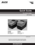
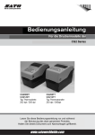
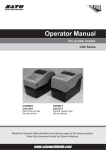
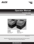
CG2 Series Quick Guide
CG208TT
CG212TT
Korean
Chinese
Thermal Transfer Type
203 dpi/305 dpi
German
English
CG2 Series
CG208DT
CG212DT
Direct Thermal Type
203 dpi/305 dpi
FCC WARNING
English
You are cautioned that changes or modifications not expressly approved by the party
responsible for compliance could void your authority to operate the equipment.
This device complies with Part 15 of the FCC Rules. Operation is subject to the
following two conditions: (1) this device may not cause harmful interference, and (2) this
device must accept any interference received, including interference that may cause
undesired operation.
This equipment has been tested and found to comply with the limits for a Class B
digital device, pursuant to Part 15 of the FCC Rules. These limits are designed to
provide reasonable protection against harmful interference in a residential installation.
This equipment generates, uses and can radiate radio frequency energy and, if not
installed and used in accordance with the instructions, may cause harmful interference
to radio communications.
However, there is no guarantee that interference will not occur in a particular
installation.
If this equipment does cause harmful interference to radio or television reception, which
can be determined by turning the equipment off and on, the user is encouraged to try
to correct the interference by one or more of the following measures:
− Reorient or relocate the receiving antenna.
− Increase the separation between the equipment and receiver.
− Connect the equipment into an outlet on a circuit different from that to which the
receiver is connected.
− Consult the dealer or an experienced radio/TV technician for help.
AC power cord with ferrite core must be used for RF interference suppression.
CG208i_E_hyo2-3.indd 1
2008/05/14 10:12:47
Safety Precautions
This section describes how to use the printer safely. Be sure to read it carefully before using the printer.
Pictographic Symbols
This instruction manual and the printer labels use a variety of pictographic symbols to facilitate safe and correct use of the printer and to
prevent injury to others and property damage. The symbols and meanings for them are given below. Be sure to understand these symbols
well before reading the main text.
Caution
Ignoring the instructions
marked by this symbol and
erroneously operating the
printer could result in injury or
property damage.
Example Pictographs
The pictograph means “Caution is required.” A specific
warning symbol is contained inside this pictograph (The symbol
at left is for electric shock).
The pictograph means “Should not be done.” What is
specifically prohibited is contained in or near the pictograph
(The symbol at left means “Disassembly prohibited”).
English
Warning
Ignoring the instructions
marked by this symbol and
erroneously operating the
printer could result in death or
serious injury.
The pictograph means “Must be done.” What is specifically to
be done is contained in the pictograph (The symbol at left
means “Unplug the power cord from the outlet”).
Warning
Do not set on an unstable area
• Do not set on an unstable area,
such as a wobbly table or
slanted area or an area subject
to strong vibration. If the printer
falls off or topples over, it could
injure someone.
Do not place containers full of water
or other liquid on the printer.
• Do not place flower vases,
cups, or other containers
holding liquids, such as water
or chemicals, or small metal
objects near the printer. If they
are spilled and get inside the
printer, immediately turn off the
power switch, unplug the power
cord from the outlet, and
contact the store, dealer, or
Support Center. Using the
printer in this condition could
cause a fire or electric shock.
Do not put objects inside the printer
• Do not insert or drop in metal
or burnable objects inside the
printer’s openings (cable
outlets, etc.). If foreign objects
do get inside the printer,
immediately turn off the power
switch, unplug the power cord
from the outlet, and contact the
store, dealer, or Support
Center. Using the printer in this
condition could cause a fire or
electric shock.
Do not use other than
the specified voltage
• Do not use other than the
specified voltage. Doing so
could result in fire or electric
shock.
Version 1 May 5, 2008 Q02330000
©2008 SATO CORPORATION
CG208i_E_00.indd I
Always ground the connections
• Always connect the printer’s
ground wire to a ground. Not
grounding the ground wire
could result in electric shock.
Handling of the power cord
• Do not damage, break, or
modify the power cord. Also, do
not place heavy objects on the
power cord, heat it, or pull it
because doing so could
damage the power cord and
cause a fire or electric shock.
• If the power cord becomes
damaged (core is exposed,
wires broken, etc.), contact the
store, dealer, or Support
Center. Using the power cord in
this condition could cause a fire
or electric shock.
• Do not modify, excessively
bend, twist, or pull the power
cord. Using the power cord in
such a condition could cause a
fire or electric shock.
When the printer has been dropped
or broken
• If the printer is dropped or
broken, immediately turn off the
power switch, unplug the power
cord from the outlet, and
contact the store, dealer, or
Support Center. Using the
printer in this condition could
cause a fire or electric shock.
Do not use the printer when
something is abnormal about it
• Continuing to use the printer in
the event something is
abnormal about it, such as
smoke or unusual smells
coming from it, could result in
fire or electric shock.
Immediately turn off the power
switch, unplug the power cord
from the outlet, and contact
the store, dealer, or Support
Center for repairs. It is
dangerous for the customer to
try to repair it, so absolutely do
not attempt repairs on your
own.
Do not disassemble the printer
• Do not disassemble or modify
the printer. Doing so could
result in fire or electric shock.
Ask the store, dealer, or
Support Center to conduct
internal inspections,
adjustments, and repairs.
Regarding the cutter
• Do not touch the cutter with
your hands or do not put
something into the cutter. Doing
so could result in an injury.
Using the head cleaning fluid
• Use of flame or heat around the
head cleaning fluid is
prohibited. Absolutely do not
heat it or subject it to flames.
• Keep the fluid out of reach of
children to prevent them from
accidentally drinking it. If the
fluid is drunk, immediately
consult with a physician.
I
2008/05/14 10:07:36
Caution
English
Do not place in areas with high humidity Power cord
• Keep the power cord away from
• Do not place the printer in
areas with high humidity or
hot devices. Getting the power
where condensation forms. If
cord close to hot devices could
condensation forms,
cause the cord’s covering to
immediately turn off the power
melt and cause a fire or
switch and do not use the
electrical shock.
•
When unplugging the power
printer until it dries. Using the
cord from the outlet, be sure to
printer while condensation is on
hold it by the plug. Pulling it by
it could result in electric shock.
the cord could expose or break
Carrying the Printer
the core wires and cause a fire
• When moving the printer,
or electric shock.
• The power cord set that comes
always unplug the power cord
from the outlet and check to
with the printer is especially
make sure all external wires
made for this printer. Do not
are disconnected before
use it with any other electrical
moving it. Moving the printer
devices.
with the wires still connected
Top cover
could damage the cords or
• Be careful not to get your
connecting wires and result in a
fingers pinched when opening
fire or electrical shock.
or closing the top cover.
• Do not carry the printer with
Also be careful the top cover
paper loaded in it. The paper
does not slip off and drop.
could fall out and cause an
injury.
Print head
• When setting the printer on the
• The print head is hot after
floor or a stand, make sure not
printing. Be careful not to get
to get your fingers or hands
burned when replacing paper
pinched under the printer feet.
or cleaning immediately after
printing.
Power supply
• Touching the edge of the
• Do not operate the power
print head with bare hands
switch or plug in/unplug the
could result in injury. Be careful
power cord with wet hands.
not to become injured when
Doing so could result in electric
replacing paper or cleaning.
shock.
• The customer should not
replace the print head.
Doing so could result in injury,
burns, or electric shock.
Loading paper
• When loading roll paper, be
careful not to get your fingers
pinched between the paper roll
and the supply unit.
When not using the printer
for a long time
• When not using the printer for a
long time, unplug the power
cord from the outlet to maintain
safety.
During maintenance and cleaning
• When maintaining and cleaning
the printer, unplug the power
cord from the outlet to maintain
safety.
Caution
(1) Reproduction in any manner of all or part of this document is prohibited.
(2) The contents of this document may be changed without prior notice.
(3) Great care has been taken in the preparation of this document, but if any problems, mistakes, or
omission are found, please contact the store or dealer where you purchased the printer.
II
CG208i_E_00.indd II
2008/05/14 10:07:37
Precautions for Installation and Handling
Printer operation can be affected by the printer environment.
Refer to the following instructions for installation and handling of CG2 Series.
Select a Safe Location
Place the printer on a surface that is flat and
Keep the printer out of high temperature and
level.
humidity.
Do not place the printer on a location that
produces vibration.
Avoid locations subject to extreme or
rapid changes in temperature or
humidity. Exposure to these conditions may cause electrical problems
within the printer.
English
If the surface is not flat and level, this
may result in poor print quality. This
may also cause malfunction and
shorten the life span of the printer.
Do not place the printer in a location subject
to water or oil.
Do not place the printer in a location
where it will be splashed with water or
oil. Water or oil entering inside the
printer may cause a fire, electric
shock, or malfunction.
Do not carry the printer when the roll
label is set. Giving serious vibration
or shock to the printer may cause
malfunction and shorten the life span
of the printer.
Avoid dust.
Do not place the printer near crane or
Dust buildup may result in poor print
quality. This may cause not only
malfunction but also shorten the life
span of the printer.
pressing machine.
Machineries such as crane and
pressing machine require large
amount of power. This may cause
electrical noise or voltage reduction.
Avoid such locations to reduce the
risk of malfunction or damage to the
printer.
Keep out of direct sunlight.
This printer has a built-in optical
sensor. Exposure to direct sunlight
will make the sensor less responsive
and may cause the label to be sensed
incorrectly. Close the top cover when
printing.
Power Supply
This printer requires an AC power supply.
Be sure to connect the printer to an AC
power supply.
Failure to do so may result in miss
operation or a malfunction.
Provide a stable source of electricity to the
printer.
Do not share the power outlets with other appliances such
as a heater and refrigerator requiring a measurable amount
of power. Also, avoid using the power outlet near where
such appliances are plugged into. This may cause voltage
reduction and malfunction.
Connect the power cord to a grounded
power outlet.
Ground
Make sure to have the facility
equipped with the ground slot.
III
CG208i_E_00.indd III
2008/05/14 10:07:37
Table of Contents
Safety Precautions ········································································· I
Precautions for Installation and Handling ···································· III
English
Unpacking····················································································· 1
Names of Parts ············································································· 3
Loading Paper ·············································································· 7
Cut Position Adjustment ····························································· 15
Loading Carbon Ribbon ····························································· 18
Connecting to a Computer ························································· 22
Turning On the Power ································································· 26
Cleaning the Printer ···································································· 28
Basic Specifications ··································································· 29
CG208i_E_01.indd 2
2008/05/14 10:08:06
Unpacking
Unpack the box, and then set up the printer.
Leaflet (Global waranty)
English
Accessory box
Cushioning material (top)
Printer
Cushioning material (bottom)
Box
The shape of the cushioning material (cushions that hold the printer in place)
may differ slightly from the diagram shown above.
1
CG208i_E_02.indd 1
2008/05/14 10:08:34
Checking Accessories
Make sure that you have received all of the following items in the package.
If there are any accessories missing, contact your nearest dealer or the store
where you purchased the printer.
Quick Guide (this manual)
English
Leaflet (Global warranty)
AC power cord
AC adapter
▲ About the Box
Please retain both the box in which the printer was packed and the cushioning
material (cushions that hold the printer in place). If you need to send in the
printer for repair, repack it in this box.
2
CG208i_E_02.indd 2
2008/05/14 10:08:34
Names of Parts
▲ Printer Unit (Unit Exterior)
Operation panel
English
Top cover
Cover open/close latch
Label discharge outlet
▲ Back (USB + LAN Interface)
USB connector
LAN connector
DC input power terminal
(Power connector)
▲ Back (USB + RS-232C Interface)
USB connector
RS-232C connector
DC input power terminal
(Power connector)
3
CG208i_E_02.indd 3
2008/05/14 10:08:35
When Top Cover Is Opened
▲ For CG208/212DT
Print head
Paper holder
English
Paper holder slide lever
Paper sensor
Platen roller
▲ For CG208/212TT
Print head
Ribbon unit
Paper holder
Paper holder slide lever
Paper sensor
Platen roller
4
CG208i_E_02.indd 4
2008/05/14 10:08:36
When Top Cover Is Opened (Cutter Type (Optional))
▲ For CG208/212DT
Paper holder
Paper holder slide lever
Paper sensor
English
Platen roller
Cutter unit
▲ For CG208/212TT
Paper holder
Paper holder slide lever
Paper sensor
Platen roller
Cutter unit
5
CG208i_E_02.indd 5
2008/05/14 10:08:38
When Top Cover Is Opened (Dispenser Type (Optional))
Paper holder
Paper holder slide lever
Paper sensor
Platen roller
Dispenser paper sensor
English
Backing paper discharge outlet
(When the dispenser unit is open)
Dispenser unit
▲ Operation Panel
POWER button
Press this button to turn the
power on or off.
ON LINE (POWER) lamp
The lamp lights green when the
printer is online and blinks green
when the printer is offline.
FEED/LINE button
Press this button to select the
printer status (online/offline) or to
feed the paper.
6
CG208i_E_02.indd 6
2008/05/14 10:08:40
Loading Paper
Roll paper
Paper feed
direction
Front
English
This printer can print on roll paper and fan-folded paper.
The method of loading the paper is different for roll paper and fan-folded paper.
The printer uses a sensor to detect I-marks in the paper in order to precisely
position the print content.
Be sure to use genuine Sato paper in this printer.
Do not use non-standard paper.
Gap 3 mm 1.5 mm
Label
Back
Paper feed
direction
Front
Back
Tag
Fan-folded paper
I-mark
Paper feed
direction
Front
Label
Back
Paper feed
direction
Tag
Fold
perforation
Front
Back
Fold
perforation
7
CG208i_E_02.indd 7
2008/05/29 10:39:53
Loading Roll Paper (Continuous/Cutter Type)
1
Pull the cover open/close latches 1 on
both sides of the printer toward you to
unlock the top cover, and then open the
top cover 2.
②
English
①
①
2
While holding the paper holder slide
lever, adjust the width of the paper
holder 1 to match the paper size.
①
①
Paper holder slide lever
3
Load the paper into the paper holder.
8
CG208i_E_02.indd 8
2008/05/14 10:08:44
4
After pulling out the paper, pass the
paper through the paper sensor.
When using a cutter type, place the
leading edge of the paper on top of the
platen roller.
5
6
English
Paper sensor
Close the top cover.
Press the top cover from above in the
direction of the arrows until it clicks into
position.
When the printer is offline, the ON LINE
(POWER) lamp blinks. Press the FEED/
LINE button 1. The printer is online and
the ON LINE (POWER) lamp lights.
When the printer is ready, press the
FEED/LINE button to output the top part
of the paper.
①
ON LINE (POWER) lamp
CAUTION
• After printing, the print head and surrounding area are hot. Be careful not to get
burned when replacing paper immediately after printing.
• Touching the edge of the print head with bare hands could result in an injury.
• The cutter is sharp. Be careful not to cut your hands.
• Be careful not to get your fingers pinched while closing the top cover.
9
CG208i_E_02.indd 9
2008/05/14 10:08:49
Loading Fan-folded Paper (Continuous/Cutter Type)
Pull the cover open/close latches on
both sides of the printer toward you to
unlock the top cover, and then open the
top cover.
English
1
2
3
Pass the paper through the opened
window at the rear of the unit.
While holding the paper holder slide
lever, adjust the width of the paper
holder 1 to match the paper size.
After pulling out the paper, pass it
through the paper sensor.
When using a cutter type, place the
leading edge of the paper on top of the
platen roller.
①
①
Paper holder slide lever
10
CG208i_E_02.indd 10
2008/05/14 10:08:54
5
Close the top cover.
Press the top cover from above in the
direction of the arrows until it clicks into
position.
When the printer is offline, the ON LINE
(POWER) lamp blinks. Press the FEED/
LINE button 1. The printer is online and
the ON LINE (POWER) lamp lights.
When the printer is ready, press the
FEED/LINE button to output the top part
of the paper.
English
4
①
ON LINE (POWER) lamp
CAUTION
• After printing, the print head and surrounding area are hot. Be careful not to get
burned when replacing paper immediately after printing.
• Touching the edge of the print head with bare hands could result in an injury.
• The cutter is sharp. Be careful not to cut your hands.
• Be careful not to get your fingers pinched while closing the top cover.
11
CG208i_E_02.indd 11
2008/05/14 10:08:58
Loading Roll Paper (Dispenser Type)
Pull the cover open/close latches on
both sides of the printer toward you to
unlock the top cover, and then open the
top cover 1.
①
English
1
2
Open the dispenser unit.
Dispenser bar
Dispenser unit
3
Remove the lead label leaving only the
backing paper, and load the paper in
the paper holder.
After pulling out the paper, pass the
paper through the paper sensor.
Pass the paper over the dispenser bar
so as to cover it.
Paper sensor
12
CG208i_E_02.indd 12
2008/05/14 10:09:01
Load the backing paper so that it sticks
out from the bottom of the dispenser
unit. If the paper is not taut, roll the
paper on the paper holder so that the
paper is taut.
Next, tightly close the dispenser unit by
pressing it in the direction of the arrow.
English
4
Output label
Output backing paper
5
Close the top cover.
Press the top cover from above in the
direction of the arrows until it clicks into
position.
13
CG208i_E_02.indd 13
2008/05/14 10:09:06
6
When the printer is offline, the ON LINE
(POWER) lamp blinks. Press the FEED/
LINE button 1. The printer is online and
the ON LINE (POWER) lamp lights.
When the printer is ready, press the
FEED/LINE button to output the top part
of the paper.
①
English
ON LINE (POWER) lamp
CAUTION
• After printing, the print head and surrounding area are hot. Be careful not to get
burned when replacing paper immediately after printing.
• Touching the edge of the print head with bare hands could result in an injury.
• The cutter is sharp. Be careful not to cut your hands.
• Be careful not to get your fingers pinched while closing the top cover.
▲ Adjusting the label dispensing stop position
Normally, the label is dispensed to the point where 2 or 3 mm of the label remain
on the backing paper. If the label is not dispensed at the regular position, use
the Phillips tip of the potentiometer adjustment screwdriver attached to the side
of the paper holder to adjust the potentiometer for the label dispensing stop
position located at the bottom right of the front panel. After adjusting the stop
position, dispense two or three labels to fix the stop position.
Potentiometer adjustment
screwdriver
For label dispensing stop position adjustment
Turn left: The stop position moves in the opposite
direction of the printing direction.
Turn right: The stop position moves in the same
direction as the printing direction.
14
CG208i_E_02.indd 14
2008/05/14 10:09:18
Cut Position Adjustment
Label Cut
The label-cut position should be between labels or at the area with only the
backing paper.
English
Label
Backing paper
Cut position
Cut Position Adjustment
If the cutting position is not at the regular position, use the Phillips tip of the
potentiometer adjustment screwdriver attached to the side of the paper holder
to adjust the potentiometer for the cut position.
Do not cut directly on a label, as the label adhesive can stick to the cutter blade
and adversely affect its cutting ability.
Potentiometer adjustment
screwdriver
For cut position adjustment
Turn left: The cut position moves in the opposite
direction of the printing direction.
Turn right: The cut position moves in the same
direction as the printing direction.
15
CG208i_E_02.indd 15
2008/05/14 10:09:22
Cutting Paper with Perforated Lines
For paper with perforated lines, cutting on or in front of the perforated lines is
prohibited. Cutting in those locations could cause the printer to malfunction.
If paper is cut at or before the perforation, use the Phillips tip of the
potentiometer adjustment screwdriver to adjust the potentiometer for the cut
position so that the paper is cut after the perforation.
English
Cut prohibited zone
Perforated line
The following items are specifications for paper that can be used by this printer,
so check them before using the printer.
1 Paper thickness (including the backing paper) is 0.06 to 0.16 mm. For
details, contact the store, dealer, or Support Center.
2 Cut accuracy is ±1.5 mm.
3 The cutter unit has a valid cut pitch of 25 to 603 mm (203 dpi)/25 to 403 mm
(305 dpi). However, the cut size may be restricted depending on the usage
conditions.
4 The perforated line +1 mm is the cut prohibited zone (Fig. 1).
5 The folded perforated line +4 to +25 mm of fan-folded paper is the cut
prohibited zone (Fig. 2).
6 After adjusting the stop position, dispense two to five labels to fix the cut
position.
25 mm
4 mm
Fold perforation
Cut prohibited
zone
Perforated line
(Fig. 1)
(Fig. 2)
16
CG208i_E_02.indd 16
2008/05/14 10:09:25
Replacing the Cutter
123 —456
English
Over time, the cutter loses its cutting ability and begins to show signs of wear.
Replace the cutter unit at this time.
Contact the store, dealer, or Support Center for purchasing options.
1 2 3 —4 5 6
Potentiometer for Adjustment
This potentiometer is for servicing the printer.
Do not change the potentiometer unless specifically instructed to do so.
Potentiometer for adjustment
17
CG208i_E_02.indd 17
2008/05/14 10:09:25
Loading Carbon Ribbon
Pull the cover open/close latches 1 on
both sides of the printer toward you to
unlock the top cover, and then open the
top cover 2.
English
1
②
①
①
2
Pull the lever on the middle of the
ribbon unit toward you to pull out the
ribbon unit.
Lever
Ribbon unit
18
CG208i_E_02.indd 18
2008/05/14 10:09:26
3
After setting the carbon ribbon in the
right side of the ribbon supply unit 1,
press the core guide 2.
①
Core guide
4
After setting the ribbon core in the right
side of the ribbon windup unit 1, check
that the projecting part on the printer is
securely inserted into the opening on
the roll. Next, press the core guide 2.
English
②
①
②
19
CG208i_E_02.indd 19
2008/05/14 10:09:30
Pass the carbon ribbon from the ribbon
supply unit beneath the print head to
the ribbon windup unit. Affix the carbon
ribbon to the ribbon core using tape,
etc., and wind it up several times in the
direction shown by the turn arrow.
English
5
Wind up several times in the
direction shown by the turn arrow.
6
Close the top cover.
Press the top cover from above in the
direction of the arrows until it clicks into
position.
20
CG208i_E_02.indd 20
2008/05/14 10:09:35
7
When the printer is offline, the ON LINE
(POWER) lamp blinks. Press the FEED/
LINE button 1. The printer is online and
the ON LINE (POWER) lamp lights.
When the printer is ready, press the
FEED/LINE button to output the top part
of the paper.
①
English
ON LINE (POWER) lamp
CAUTION
• After printing, the print head and surrounding area are hot. Be careful not to get
burned when replacing the carbon ribbon immediately after printing.
• Touching the edge of the print head with bare hands could result in an injury.
• Be careful not to get your fingers pinched while closing the top cover.
21
CG208i_E_02.indd 21
2008/05/14 10:09:39
Connecting to a Computer
Standard Interface
English
▲ USB + LAN Type
LAN connector
USB connector
1 Turn on the printer while pressing the FEED/LINE button.
Continue pressing the FEED/LINE button until the ON LINE (POWER) lamp
blinks green.
Each
time you press the FEED/LINE button, the ON LINE (POWER) lamp
2
indicator changes.
When using the USB connector, check that the ON LINE (POWER) lamp is
alternating between green and red.
When using the LAN connector, check that the ON LINE (POWER) lamp is
blinking green.
3 Press the FEED/LINE button for at least three seconds to register the
connector type.
Check
that the ON LINE (POWER) lamp is lit green, and then turn off the
4
printer. Turn on the printer again to activate the connector.
22
CG208i_E_02.indd 22
2008/05/14 10:09:41
▲ USB + RS-232C Type
RS-232C connector
English
USB connector
1 Turn on the printer while pressing the FEED/LINE button.
Continue pressing the FEED/LINE button until the ON LINE (POWER) lamp
blinks green.
2 Each time you press the FEED/LINE button, the ON LINE (POWER) lamp
indicator changes.
When using the USB connector, check that the ON LINE (POWER) lamp is
alternating between green and red.
When using the RS-232C connector, check that the ON LINE (POWER) lamp
is blinking green.
3 Press the FEED/LINE button for at least three seconds to register the
connector type.
4 Check that the ON LINE (POWER) lamp is lit green, and then turn off the
printer. Turn on the printer again to activate the connector.
23
CG208i_E_02.indd 23
2008/05/14 10:09:42
Expansion Interface (Optional)
English
▲ Wireless LAN Interface
1 Turn on the printer while pressing the FEED/LINE button.
Continue pressing the FEED/LINE button until the ON LINE (POWER) lamp
blinks green.
2 Each time you press the FEED/LINE button, the ON LINE (POWER) lamp
indicator changes.
When using the wireless LAN connector, check that the ON LINE (POWER)
lamp is alternating between green and red.
3 Press the FEED/LINE button for at least three seconds to register the
connector type.
4 Check that the ON LINE (POWER) lamp is lit green, and then turn off the
printer. Turn on the printer again to activate the connector.
24
CG208i_E_02.indd 24
2008/05/14 10:09:43
Keypad (Simple input device (Optional))
English
RS-232C connector
Communication cable
Keypad (Simple input device)
1 Turn on the printer while pressing the FEED/LINE button.
Continue pressing the FEED/LINE button until the ON LINE (POWER) lamp
blinks green.
2 Each time you press the FEED/LINE button, the ON LINE (POWER) lamp
indicator changes.
When using the keypad, check that the ON LINE (POWER) lamp is blinking
red.
3 Press the FEED/LINE button for at least three seconds to register the
connector type.
4 Check that the ON LINE (POWER) lamp is lit green, and then turn off the
printer. Turn on the printer again to activate the connector.
5 Connect the communication cable of the keypad to the RS-232C connector
on the printer. Check the orientation of the connector to be connected. While
bracing the printer with one hand, securely connect the cable of the keypad
to the printer.
The keypad (simple input device) can be used when the printer standard interface
is the USB + RS-232C type.
25
CG208i_E_02.indd 25
2008/05/14 10:09:44
Turning On the Power
Power Setting
Plug the DC power cord of the AC adapter into the printer and turn on the
power.
Connect the AC power cord to the AC
adapter.
English
1
AC adapter
AC power cord
2
Connect the printer
AC adapter
AC power outlet. When plugging the
DC power cord into the printer's power
connector, make sure the DC power
cord connector is oriented properly.
When plugging in the DC power cord
to the printer, use one hand to hold the
printer while using the other hand to
plug in the cord.
DC input power terminal
(Power connector)
Make sure the flat side
of the DC power cord is
facing up.
Plug
DC power cord
26
CG208i_E_02.indd 26
2008/05/21 10:56:40
The plug of the supplied AC power cord
is 3-pronged. One of the 3-pronged
electrodes is dedicated to grounding.
When the outlet is a 3-prong type, plug
the AC power cord directly into it.
English
3
CAUTION
• Be sure to connect the ground wire to the ground. Not connecting the ground
wire could result in electrical shock.
• The power cord set supplied with this printer is only for use with this printer. Do
not use it for other electrical products.
4
P re s s t h e P O W E R b u t t o n o n t h e
operation panel of the unit. The ON
LINE (POWER) lamp lights. Check that
the ON LINE (POWER) lamp is lit.
POWER button
ON LINE (POWER) lamp
CAUTION
• Do not operate the power switch or plug in/unplug the power cord with wet
hands. Doing so could result in electric shock.
27
CG208i_E_02.indd 27
2008/05/14 10:09:47
Cleaning the Printer
This printer is used to print barcodes and data containing important
information. If the printer parts become dirty, the printer may not be able to
print barcodes and data accurately, and it may malfunction. Therefore, it is
important to regularly clean the printer.
Recommended Cleaning Schedule
English
It is recommended that you clean the printer with the cleaning sheet (sold
separately) after six paper rolls or 300 meters of paper are discharged.
Precautions When Cleaning the Printer
Observe the following precautions when cleaning the printer.
• The above recommended cleaning schedule is only for reference. Clean the
printer at a convenient time and according to actual printer conditions.
• Use cotton swabs and a cotton cloth when cleaning the printer parts.
• When using a screwdriver or other utensils during cleaning, be careful not to
scratch the printer parts. Do not use utensils as tools to clean the print head.
• Be sure to turn off the printer before cleaning.
28
CG208i_E_02.indd 28
2008/05/14 10:09:50
Basic Specifications
CG208DT
203 dpi
(8-dot/mm)
Direct Thermal
CG212DT
305 dpi
(12-dot/mm)
CG208TT
CG212TT
203 dpi
305 dpi
(8-dot/mm)
(12-dot/mm)
Thermal Transfer (Direct Thermal/
Thermal Transfer)
Printing effective area 56 mm wide × 600 mm pitch
56 mm wide × 400 mm pitch
Label issuing
Standard: Continuous mode, Tear off mode, Sensor off mode
mode
Optional: Dispenser mode, Cutter mode
Printing speed
50, 75 or 100 mm/sec (Setting: 50, 75, 100)
2, 3 or 4 inches/sec (Setting: 2, 3, 4)
Unprintable area
Label : Length direction Upper: 1.5 mm or less Lower: 1.5 mm or less
(Not including backing paper)
Width direction Left: 1.5 mm or less Right: 1.5 mm or less
(Not including backing paper)
Tag : Length direction Upper: 0.8 mm or less Lower: 0.8 mm or less
Width direction Left: 0.8 mm or less Right: 0.8 mm or less
Paper type
Roll paper, fan-folded paper
Paper shape
Only use paper manufactured and/or specified by SATO.
Paper thickness
60 to 190μm (0.06 to 0.19 mm)
Label size
See page 31 for the label size.
Outer diameter of Label: Maximum ø130 mm
paper/Roll size
Inner diameter of roll: ø40 mm (ø1.5 inches)
Wrist bands: Maximum ø110 mm
Inner diameter of roll: ø40 mm (ø1.5 inches)
Tag: Maximum ø250 mm
Inner diameter of roll: ø76 mm (ø3 inches)
* Use an external supply unit when setting a tag.
Ribbon size/
Ribbon length: 50 m
Ribbon type/
Ribbon width: 59 mm
Ribbon winding
—
Winding direction: Face out
direction
Ribbon winding method: Roll-wound
ribbon
Standard installed fonts
Bit map font
ANK font
English
Model name
Head density
(Resolution)
Printing method
XU, XS, XM, XB, XL, OCR-A, OCR-B
Kanji font
Rasterized font
Barcode
2D barcode
Composite symbol
CG208i_E_02.indd 29
OCR-A (22×33)
OCR-A (15×22)
OCR-A (22×33)
OCR-A (15×22)
OCR-B (30×36)
OCR-B (20×24)
OCR-B (30×36)
OCR-B (20×24)
Supported by downloading one of the following kanji fonts.
1 Japanese (16×16, 22×22, 24×24/Kaku Gothic (JIS Std 1, 2, JIS X208))
2 Chinese (24×24 GB2312)
3 Korean (24×24 KSX1001)
CG Times, CG Triumvirate
UPC-A/UPC-E, JAN/EAN, CODE39, CODE93, CODE128, GS1-128
(UCC/EAN-128), CODABAR (NW-7), ITF, Industrial 2 of 5, Matrix 2 of 5,
BOOKLAND, MSI, POSTNET, GS1 DataBar (RSS)
QR Code, Micro QR, PDF417, Micro PDF, MAXI Code,
GS1 DataMatrix (ECC200)
JAN/EAN, UPC-A/UPC-E, GS1-128, GS1 DataBar (RSS)
29
2008/05/22 20:19:34
English
Model name
Printing direction
(Characters/
Barcode)
Barcode ratio
Magnification ratio
(Characters/
Barcode)
Self-diagnostic
function
CG208DT
CG212DT
CG208TT
CG212TT
Characters: 0, 90°, 180°, 270°
Barcode: Parallel 1 (0°), Parallel 2 (180°), Serial 1 (90°), Serial 2 (270°)
Dimensions
Weight
Power
specifications
Power consumption
Environmental
conditions (Temperature/
Humidity)
Options
128 (W) × 235 (D) × 173 (H) (mm)
1.5 kg
1.6 kg
AC adapter
Input power voltage: AC 100 to 240 V ±10 %
60 W (In standby: 2.5 W)
Operating environment: 0 to 35°C, 30 to 80 % RH (However, no condensation)
Storage environment: –10 to 60°C, 15 to 85 % RH (However, no condensation)
(Not including ribbon, labels, and other supplies.)
- Cutter unit
- Dispenser unit
- Wireless LAN (802.11b/g Auto switch) interface (External)
- Keypad
Select one of the following. (The factory will provide the unit with the
selected interface.)
1 USB (Full speed) and RS-232C (D-SUB 9-pin)
2 USB (Full speed) and LAN (10 BASE/100 BASE-TX auto switching)
* The RS-232C connector can be used to connect the printer to a computer
or the keypad.
ON LINE (POWER) (Green/Red)
Button: POWER, FEED/LINE
- I-mark sensor adjustment (Adjusts the sensor slice level.)
- Label gap sensor adjustment/Center tag hole sensor adjustment (Adjusts
the sensor slice level.)
- Cut position adjustment (Can only be adjusted when the cutter unit is attached.)
- Label dispenser stop position adjustment (Can only be adjusted when the
dispenser unit is attached.)
I-mark sensor (Reflective type)
Label gap sensor (Transmissive type)
FCC15B Class B, CE (EN55022, EN55024), GB9254-1998, GB17625.1 (2003),
KN22, KN24
Interface
LED
Operation button
Potentiometer for
adjustment
Paper length
detection sensor
Noise (EMC)
standard
1:2, 1:3, 2:5, Free specification
Characters: Vertical ×1 to ×12, horizontal ×1 to ×12
Barcode: ×1 to ×12
-
Broken head element check
Paper end detection
Cover open detection
Test print
-
Broken head element check
Paper end detection
Cover open detection
Test print
Ribbon end detection
Ribbon near-end detection
Notice regarding the registered trademarks and trademarks of other companies
QR Code is a registered trademark of DENSO WAVE INCORPORATED.
30
CG208i_E_02.indd 30
2008/05/22 20:19:34
▲Label size
CG212DT/CG212TT
Continuous type
Pitch: 9 to 403 mm
Width: 15 to 63 mm
Cutter type
Pitch: 25 to 403 mm
Width: 15 to 63 mm
Tear-off type
Pitch: 15 to 403 mm
Width: 15 to 63 mm
Continuous type
Pitch: 6 to 400 mm
(Backing paper 9 to 403 mm)
Width: 15 to 60 mm
(Backing paper 18 to 63 mm)
Cutter type
Pitch: 22 to 400 mm
(Backing paper 25 to 403 mm)
Width: 15 to 60 mm
(Backing paper 18 to 63 mm)
Tear-off type
Pitch: 12 to 400 mm
(Backing paper 15 to 403 mm)
Width: 15 to 60 mm
(Backing paper 18 to 63 mm)
Dispenser type
Pitch: 22 to 100 mm
(Backing paper 25 to 103 mm)
Width: 15 to 60 mm
(Backing paper 18 to 63 mm)
English
Model name CG208DT/CG208TT
Non-adhesive Continuous type
paper/Tag
Pitch: 9 to 603 mm
Width: 15 to 63 mm
Cutter type
Pitch: 25 to 603 mm
Width: 15 to 63 mm
Tear-off type
Pitch: 15 to 603 mm
Width: 15 to 63 mm
Label
Continuous type
Pitch: 6 to 600 mm
(Backing paper 9 to 603 mm)
Width: 15 to 60 mm
(Backing paper 18 to 63 mm)
Cutter type
Pitch: 22 to 600 mm
(Backing paper 25 to 603 mm)
Width: 15 to 60 mm
(Backing paper 18 to 63 mm)
Tear-off type
Pitch: 12 to 600 mm
(Backing paper 15 to 603 mm)
Width: 15 to 60 mm
(Backing paper 18 to 63 mm)
Dispenser type
Pitch: 22 to 100 mm
(Backing paper 25 to 103 mm)
Width: 15 to 60 mm
(Backing paper 18 to 63 mm)
*Some restrictions may apply to the paper sizes that can be used depending on the
type of paper, usage environment, and application.
31
CG208i_E_02.indd 31
2008/05/14 10:09:51
English
32
CG208i_E_02.indd 32
2008/05/14 10:09:52