1
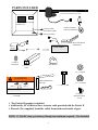
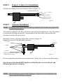
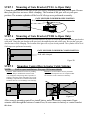
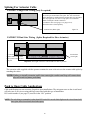
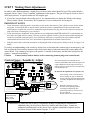
USAutomatic
PATRIOT
High Quality Low Voltage
Vehicular Swing Gate Operator
Solar or AC Charged
PATRIOT I Single Swing Gate Operator
PATRIOT II Dual Swing Gate Operator
Installation/Owners Manual
PROUDLY MADE IN THE USA
www.usautomatic.com
INTRODUCTION
This operator is intended to be installed on vehicular Class I or Class II gates as defined by
UL 325. Maximum gate load not to exceed 650 pounds.
PLEASE READ THIS ENTIRE MANUAL CAREFULLY PRIOR TO INSTALLATION.
In doing so, along with performance of the installation in step-by-step order, you
will achieve optimal results. We strongly recommend that all installation and
service personnel pay particularly close attention to the safety systems section of
this manual and UL 325. In addition to the current sense feature that is provided,
other safety devices are necessary to make each particular installation as safe as
possible to reduce the risk of personal injury and/or property damage. A trained
and authorized service technician or the factory should be consulted for assistance.
Cautions - Very Important
Do not attempt to enter the gate area while the gate is moving. Wait until the gate comes to a
complete stop.
Operate the gate only when it is fully visible, free of persons or obstructions, and
properly adjusted.
Do not allow children to play in the area of the gate. Do not allow anyone to ride on the gate.
Do not allow children to play with the remote control or any other activation device.
Do not attempt to "beat the gate" while the gate is opening or closing. This is extremely
dangerous.
Test the current sense feature and all safety devices regularly to insure correct operation.
Study the entire Safety Section (page 17-20), paying particularly close attention to the
Entrapment zones on page 18-20 and be aware of these areas not only during use but also
during any adjustments to the unit.
The USAutomatic battery charger is designed to operate with 12 vdc deep cycle batteries
rated at 60-amp hour minimum. Gel type is recommended.
Modifying the charger AC supply cord will void the charger warranty.
Other Safety Standards
All control stations should be located at least 6 feet from any moving part of the gate or
operator.
Do not ever install any control device where a user will be tempted to reach through the
gate or fence to activate a gate.
© USAutomatic, LTD - 2005 rev ZJ
All rights reserved. No part of this may be reproduced by any means
without the expressed written consent of the publisher.
1
Table Of Contents
Page
Introduction...................................................................................... 1
Table of Contents............................................................................. 2
General Requirements/Gate Qualifications & Applications ........... 3
Importance of a Properly Designed Gate ........................................ 4
Mounting Site Review ..................................................................... 4
Parts Included List ........................................................................... 5
Hinge Mount Tube Installation/Pull to Open/Push to Open ........... 6
Hinge Mount Tube Installation/Vertical Height ............................. 7
Preparation of Actuator for Installation........................................... 8
Actuator Installation ...................................................................... 8,9
Mounting the Gate Bracket/Control Box/Actuator Cable Splicing 9
Master/Slave Dual Gate Wiring/Push to Open Applications .........10
Charging Source Installation/Solar or AC......................................11
Installing Safety Placards/Secondary Entrapment Siren ................11
Final Adjustments Current Sense Adjust ......................................12
Limit Switches/Limit Assembly Operation....................................13
Circuit Board & Terminal Description...........................................14
Function of Programming Switch Settings DS1 ............................15
Function of Programming Switch Settings DS2 ............................16
Emergency Manual Release ...........................................................16
Safety Section .............................................................................. 17-20
Periodic Service ..............................................................................21
Troubleshooting Introduction .........................................................21
Troubleshooting Guide ................................................................ 21-26
Accessory Wiring Diagrams........................................................ 27-29
Programming Transmitter / Receiver ............................................29
Magnetic Wire Sensing Loops .................................................... 30-32
Warranty Statement / Mail in Registration.......................... Back Cover
2
GENERAL REQUIREMENTS
General hand/tools such as combination wrenches, tape measure, level, clamps, etc. are
required. Your particular installation may require a drill or other hardware not provided.
Welding by a qualified welder is the recommended method of securing the linear actuator
mounts to the gate and hinge post. Bolt on brackets is an option, but they must be very
securely attached (i.e. carriage bolts with lock nuts and washers). Lag type bolts are not
recommended. Loose or unstable operator mounts will result in improper operation.
BATTERY REQUIRED FOR OPERATION (NOT INCLUDED).
We recommend a 12-volt deep cycle gel battery rated at a minimum of 60-amp hours. The
actuator harness is equipped with ring terminals designed to connect to bolt type battery post.
The USAutomatic charger is designed for this type of battery and using a smaller amp hour
battery may cause damage to the charging system.
IMPORTANT CAUTIONS:
1. Do not test or operate this unit without the actuator securely attached to the gate. Serious
damage to the actuator limit switch assembly may occur if attempted.
2. Do not perform any welding with the actuator cable plugged into the control board or the
battery connected. Serious damage to the control board and/or battery will occur if
attempted.
3. Always disconnect the battery power from the unit prior to connecting any devices.
GATE QUALIFICATIONS/APPLICATIONS
GATE LENGTH/WEIGHT
This gate operator is rated for vehicular class I or class II swing gates up to 16 feet in length
and up to 650 pounds in weight as defined by UL325. If your gate exceeds either one of
these limits, please consult a qualified technician or the factory for alternative solutions.
(Example: Convert one 20' gate into two 10' gates and use a dual gate operator.)
Note:
The total gate opening normally cannot exceed 110 degrees.
Consult a service technician or the factory if greater opening is required.
GATE CYCLES PER DAY
Solar charged systems are limited on the number of cycles they can provide on a daily basis.
System design must consider stand-by current consumption of all accessories and number of
cycles expected per day. Using solar friendly accessories a solar operator in most installations
will not need additional solar panels. Contact the factory for help designing the system. This
actuator type opener, whether AC or Solar charged, should never be used in applications,
which exceed 150 complete open/close cycles per day. Holding the gate open can decrease
cycles during high cycle time periods. If more cycles are required, a high traffic gate opener
should be used.
3
IMPORTANCE OF A PROPERLY DESIGNED GATE
As a general rule a gate, which is to be automatically operated must be stronger and
smoother than one, which will be manually operated. Since the gate is a major component
of the system, great care and concern must be given to the gate design.
A GATE OPERATOR CANNOT OVERCOME A POORLY DESIGNED GATE.
A.
Does the gate swing smoothly without binds or excessive resistance? Swing gates
should swing level and plumb to prevent the operator from having to lift the gate open
or closed. Swing gates should not require a wheel to support them. Wheels usually
create drag, which will cause operator problems. A wheel is generally a sign of a weak
hinge system or a weak gate frame.
B.
Is the gate frame of substantial strength without excessive weight? Will the frame
withstand normal wind load conditions without sway or vibration? Will the gate close
correctly without being hand-guided or lifted to close?
C.
Are the hinges suited for the number of cycles expected per day?
We recommend bearing type hinges to reduce friction drag.
D.
Will a reinforcement brace be required to attach the operator to the gate or
does a suitable cross member exist in the gate design?
If any of these problems exist, they must be corrected to achieve a reliable automatic gate
system.
MOUNTING SITE REVIEW
Installers should ask themselves these questions prior to installation and predetermine the
solution to any problems, which may occur.
A.
B.
C.
D.
E.
F.
G.
H.
Does sufficient space exist for mounting and future servicing of the operator and
control box?
Will the unit push the gate open to the outside or pull the gate open to the inside?
How will the actuator mounts be secured at the hinge and to the gate?
How will the control box be mounted securely enough to support the weight of the
battery and can it be located within 8 feet to prevent splicing of the actuator cable?
How will power be brought to the control box if AC charged?
How and where will the solar panel mount if solar charged so that optimum sunlight is
received?
How will exterior control wiring, if any, be brought to the control box?
Have all safety concerns been addressed? (See Safety Section Pgs. 17-20)
4
PARTS INCLUDED
*Actuator Arm with 8 foot of Cable
Cabinet with Control Board
and Receiver
Antenna Assembly
with coax and bracket
*Actuator Cable
Strain Relief Clamp
Snap in Grommet
*Solar Panel with Bracket
and hardware
Battery
Charger
1- 2 button
Transmitter
Solar Panel
OR
* Gate Bracket
2” X 2” X 17”
*Tube
*5- ½” washers
WARNING
*Manual Release Pin
And Clip
*1- ½” Locknuts
* ½” X 4 ½” Bolt
A Moving Gate Has The Potential Of Inflicting Serious Injury Or Death
Persons are to keep clear! The gate is able to be moved without prior warning.
Do not let children operate the gate or play in the gate area.
Persons are to operate the gate only when the gate area is in sight and free of people and obstructions.
Secondary
Entrapment Siren
+12vdc
2- Placards
*For Patriot II quantity is doubled.
Additionally, 40’ of Master/Slave Actuator cable provided with the Patriot II
Placards (Two supplied) should be visible from inside and outside of gate.
NOTE: 12 Volt DC deep cycle battery 60-amp hour minimum required. (Not Included)
5
STEP 1 Hinge Mount Tube Installation (Part 1)
PULL TO OPEN / TOP VIEW
(SEE BOTTOM OF PAGE FOR PUSH TO OPEN)
(Left-handed installation shown. Reverse for right-handed installation)
Optional masonry column
Concrete fill recommended.
Dimensions from hinge pivot point
Steel post 4 inch
minimum diameter
¼ inch thick wall min.
GATE
13 inches
6 inches
Hinge Mount Tube
cut as necessary to achieve
dimensions shown.
Gate Open Direction
Figure 1A
Other Typical Methods for
Pull to Open Applications
Push to Open Applications
Wood post add metal plate and
bolt on with ½ inch carriage
bolt/washers/nuts.
Round Post
saddle cut
tube for fit
Thin wall
post add
support
prevent
twisting.
Hinge mount tube
must be level
In all directions for proper
alignment and operation.
Level
Figure 1B
STEP 1 Hinge Mount Tube Installation (Part 2)
PUSH TO OPEN / TOP VIEW
(SEE TOP OF PAGE FOR PULL TO OPEN)
(Left-handed installation shown. Reverse for right-handed installation)
Gate Direction of Travel
Dimensions from hinge pivot point
Steel Post
4” min
¼ thick
GATE
6 inches
11 in
Hinge mount tube (cut as necessary to achieve
dimensions shown).
Figure 1C
Regardless of method used, the hinge mount tube should be very secure since the entire force of the gate is
directed to this mount. The post must be of adequate strength to resist twisting as well.
Conform to dimensions shown at top of page always. See page 7 to locate height of hinge mount tube on post.
Note: USAutomatic is not responsible for failure to comply with UL325 standards, local
building codes or improper installations.
6
STEP 1 Hinge Mount Tube Installation (Part 3)
VERTICAL HEIGHT POSITIONING
Refer to figures 2B-2F to determine the best location for the actuator on the gate. Then use figure 2A to
determine the height of the hinge mount tube and gate bracket. The middle of the gate is the ideal location for
the actuator. The top or bottom of the gate frame are also possible locations.
Gate Bracket
5/8 inch
Center Line
Hinge mount tube
Figure 2A
Incorrect Installation
Correct Installation
Figure 2B
Figure 2E
Figure 2C
Figure 2F
IMPORTANT:
The gate bracket must be welded in an area that can
withstand the full force of the gate. Do not simply weld
across a few pickets or bending of the pickets will occur.
Add a cross bar if necessary or weld the bracket to the
gate frame.
Figure 2D
7
STEP 1
Prepare Actuator for Installation
Assemble the actuator to the gate bracket as shown in figure 3A
½ inch Manual Release Pin
2- ½” washers
Gate Bracket
Manual release pin
must pivot freely.
Figure 3A
STEP 2
NOTE:
Actuator Installation
To simplify Limit switch adjustment during installation, the actuator may temporarily
be mounted upside down.
The actuator is adjusted to the fully retracted or open position from the factory. Once the actuator
is connected to the hinge mount tube, swing the gate to the desired fully open position and
determine location of the gate bracket.
Mount the actuator to the hinge mount tube as shown in Figure 4A.
Support the free end of the unit while mounting.
½” x 4 ½ bolt
½” washers
½” locknut
Tighten firmly. Do not over tighten.
Actuator must pivot freely.
Figure 4A
Do not permanently mount the actuator upside down. Mount only as shown in the illustrations.
Open the gate to the desired OPEN position and block in place to secure the gate and
determine gate bracket weld point.
NOTE:
The total opening cannot exceed 110 degrees. Consult a service technician or the
factory if greater opening is required.
8
STEP 3
Mounting of Gate Bracket (PULL to Open Only)
Clamp the gate bracket to the gate at the previously determined point and weld to gate. Be sure
that your gate does not move while clamping. The location of the gate will set your open
position. The actuator cylinder will be level if all steps were performed accurately.
GATE SECURED IN DESIRED OPEN POSITION
Weld while clamped
Figure 5A
STEP 4
Mounting of Gate Bracket (PUSH to Open Only)
Close the gate to the desired CLOSED position and block in place to secure the gate and determine gate bracket
weld point. Clamp the gate bracket to the previously determined point and weld to gate. Be sure that your gate
does not move while clamping. The location of the gate will set your closed position. The cylinder will be level
if all steps were performed accurately.
GATE SECURED IN DESIRED CLOSED POSITION
Weld while clamped
Figure 5B
STEP 5
NOTE:
Mounting Control Box/Actuator Cable Splicing
Push to open installations. See page 10 for more details.
Correct – Install control box to fence by welding
or screws. Keep in mind that the actuator cable
is 8’ in length (avoid splicing cable if possible) if
splicing is necessary water tight splices are a must.
If drilling is required remove control board and all
electronic devices to avoid damage from shavings.
Incorrect – Do not mount in areas by automatic
sprinklers or flood prone areas. It is important that
all electronics in the control box remain dry.
Figure 6A
After securely mounting control box install battery and all electronic components. Route
actuator cable through the bottom of control box; do not connect to battery or control board at
this time.
9
Splicing For Actuator Cable
PATRIOT I Single Gate Wiring (only if required)
If 8’ actuator cable must be spliced a watertight junction box must
be used to prevent moisture from splice. The wire used for the
splice should be no smaller than the actuator cable wire provided.
Use only approved wire nuts or crimp splices for connection.
Make second splice inside control box.
5-conductor cable (2-12gauge, 3-18 gauge wires).
Extension cable is sold separately.
Junction Box (Water tight)
Figure 7A
PATRIOT II Dual Gate Wiring (Splice Required for Slave Actuator)
Master Gate
40’ extension cable supplied.
Install conduit from control
box to junction box on slave
gate post.
Slave Gate
Driveway
Junction Box
(water tight)
Conduit
Important: The length of the slave cable should be as short as possible.
The extension cable supplied with the operator contains the same color wires as the actuator cable splice by
matching the colors.
NOTE: Failure to install extension cable into watertight conduit and keep all connections
dry will result in future problems.
Push to Open Cable Applications
Cable modifications are not necessary for push to open installations. The microprocessor on the circuit board
will take care of all wire reversing and logic associated with this type of installation.
DS1 switch number 9 (see page 15) must be in the “ON” position.
NOTE: The only thing to remember is that when DS1 switch 9 is on the Limit lights on the circuit board will
show open when closed and closed when open.
10
STEP 6
Installation of Charging Source
SOLAR PANEL
Locate and mount the solar panel bracket so that the panel faces southwest and maintains the preformed 45degree angle. The standard cable is 10' in length and must feed in through the bottom of the control box. Pay
attention to the distance when determining you’re mounting location. Although the cable can be extended with
watertight connectors, charging power is diminished. Sometimes it is necessary to locate the panel farther away
to achieve optimum sunlight, but consider that optimum sunlight might not mean optimum charging if the
distance is to great. Use #16 gauge wire or larger and keep length as short as possible.
Assemble panel(s) to bracket
with supplied hardware.
Patriot II is supplied with two
panels and brackets.
Red wire +
PATRIOT I
Panels facing
Southwest.
Black wire -
Deep cycle
Battery
Note:
PATRIOT II
Avoid shaded areas if possible. Panels should face southwest for optimum charging. See
explanation above for details.
AC CHARGER
Locate and install the AC battery charger inside the control box. The charger requires a receptacle for 110-volt
AC supply; recommended location is inside the control box. A licensed electrician per local building codes
should install the receptacle. Modifying the charger power cord will void the warranty.
Note: USAutomatic recommends an AC surge protector on all 110-volt installations.
Especially in lightning prone areas. Do not modify the AC cord on the charger.
Control
Board
+
receiver
Do not connect battery wires from actuator/control board at this time.
Do not connect actuator cable to the control board until the battery
leads from the actuator cable have been connected to the battery,
doing so will cause damage to the control board.
JUNCTION BOX MOUNTED INSIDE CABINET
Battery
Charger
CONDUIT
INSTALL SNAP IN GROMMET TO PROTECT WIRES.
STEP 7 Installing Safety Placards
Mount safety placards on gate. Two signs are provided. Place one sign on each side of the gate where it will be
highly visible to anyone on either side of the gate.
STEP 8 Installing Secondary Entrapment Siren
The secondary entrapment siren connects to the control board (see pages 12,31). This siren is very loud and will
be activated anytime the current sense circuit stops the gate twice prior to reaching a fully open or close limit. The
reset button on the control board (see page 12) must be pushed to turn off the siren, and reset the control board.
11
STEP 9 Making Final Adjustments
In order to make final adjustments, a signal device such as a radio control should be used. The control board is
equipped with an “Open / Close Command” pushbutton for this purpose. The gate will open if closed or close if
in the open position. A signal in mid-travel will stop the gate.
If your unit was purchased with a radio receiver, it is important that you change the default code settings.
Please consult a dealer for assistance. RCS transmitter / receiver instructions are on page 29.
IMPORTANT NOTES
Locate the actuator cable plug and be aware that you may need to disconnect it if the cylinder over travels the desired
stop points. You should be able to stop the motor with the open/close command button or the reset button on the
control board or a signal from your device without having to disconnect the plug, but in cases of incorrect wiring, the
plug can be used as an emergency power shut-off.
1.
2. Locate the sensitivity adjustments. Notice that there are two adjustments MASTER and SLAVE we intentionally set
the sensors at a highly sensitive setting. This may need to be adjusted to achieve gate movement without tripping the
sensitivity circuit and causing the gate to reverse direction. If the gate reverses direction twice and then stops the
control board will need to be reset. See Current Sense Adjustment and reset button location below.
Study the limit switch section and instructions on adjusting the limit switches prior to battery hook up. See page 13 for
details.
3.
If you have an understanding of the sensitivity feature, how to disconnect the actuator plug in an emergency, and
how to adjust the limit switches, then proceed to hook up the battery leads and connect the actuator plug to the
control board. The red battery lead goes to the positive + terminal on the battery and the black lead goes to the
negative - terminal on the battery.
Caution:
Connect battery leads to battery before connecting actuator plug to the control board.
Current Sense / Sensitivity Adjust
USAutomatic
MADE IN USA
PATRIOT CONTROL BOARD
MASTER
SLAVE
Sensitivity
Sensitivity
5
5
0
10
0
CURRENT SENSE
ADJUSTMENT
The control board has two adjustments for
sensitivity MASTER and SLAVE. Dual gates will
require adjustment of both, adjust sensitivity so
that the gate force required to sense an obstruction
is at the desired level.
Timer
5
10
0
CURRENT SENSE
ADJUSTMENT
5
10
TIMER TO CLOSE
ADJUSTMENT
ADJUSTMENT
DS1
DS1 SWITCH SETTINGS
O
N
1
2
3
4
5
6
7
8
9
10
SW-1
FACTORY SETTINGS
AUTO CLOSE TIMER ENABLE
OFF
SW-2
TIMER TO CLOSE WILL ACTIVATE ON LIMIT ONLY
SW-3
MASTER GATE ENABLE
0
ON
ON
BOTH ON FOR DUAL
SW-4
SLAVE GATE ENABLE
SW-5
SOLENOID LOCK OPTION, SEE INSTALLATION MANUAL
OFF
SW-6
SOFT STOP RETRACT ENABLE
OFF
SW-7
SOFT STOP EXTEND ENABLE
OFF
15
OFF
SW-8
STOP CIRCUIT ENABLE
OFF
SW-9
SW-10
OPERATING DIRECTION REVERSE
SOFT START ENABLE FOR SW6 AND SW7
OFF
OFF
15
10
Do not turn the adjustment screw past 0 or 10.
LED INDICATOR
S2
If the sensing circuit is activated twice
before reaching an open or closed limit
the unit will stop operating and sound the
secondary entrapment siren and require a
reset.
J2 INDICATORS
1-
+12V OUT 1.5 AMP MAX
2-
COMMON GROUND
3-
PUSH BUTTON INPUT
4-
OPEN SAFETY EDGE
5-
CLOSE INPUT
6-
SECONDARY ENTRAPMENT DEVICE INPUT
7-
COMMON GROUND
8-
STOP CIRCUIT INPUT N/C
9-
FREE EXIT / OPEN INPUT
10-
UNDER GATE / CENTER LOOP INPUT
11-
SAFETY LOOP / REVERSING EDGE INPUT
12-
MOTION DETECTOR INPUT
1
2
3
4
RESET
1
Vehicular Gate Operator
Class I or Class II per UL325
Gate Weight Max. Load: 650 lbs.
2
3
4
5
6
7
8
9 10 11 12
J2
OPEN/CLOSE
COMMAND
Entrapment
Siren Output
C
O
M
M
O
N
G
N
D
O
U
T
P
U
T
+
1
2
V
S
O
L
O
N
O
I
D
L
O
C
K
C
O
M
M
O
N
G
N
D
M
A
G
L
O
C
K
S
E
C
U
R
I
T
Y
RESET
O SOLONOID LOCK ENABLE
N MAGNETIC LOCK ENABLE
SECURITY SHUNT ENABLE
MOTION DETECTOR ENABLE
S
H
U
N
T
Secondary
Entrapment Siren
Red +12 vdc
Black Ground
Remember if the gate reverses
direction when operating without
contacting an obstruction, then
minimizing sensitivity (increase force)
may be required.
Do not increase more than necessary.
CAUTION: To reduce the risk of injury, USAutomatic strongly recommends the installation of
additional safety devices such as Photo Eye Sensors and Safety Edges. Consult an
authorized installing dealer or the factory for a complete explanation of options and see
the Safety Section of this manual on pages 17 to 20.
12
LIMIT SWITCHES
The limit switch adjustments are located on the bottom of the actuator. Remove the dust plug to make
adjustments. The normal settings from the factory allow for 18" of travel (approx. 70% opening). You will most
likely have to adjust the extend or close limit for your installation. The adjustments are labeled "Extend" and
"Retract" on the dust plug. Flat blade screwdriver is included with the operator.
If soft stop is going to be used turn switch 6 or 7 (see page 15) on at this time. Prior to operation the extension
tube needs to be turned about 5 or 6 turns in the counter clockwise direction. Disconnect from gate bracket to
turn.
NOTE: ALL ADJUSTMENTS SHOULD BE MADE IN THE MID TRAVEL (1/2 OPEN) POSITION. DO
NOT FORCE THE ADJUSTMENT; FORCING WILL DAMAGE THE LIMIT ASSEMBLY. REMOVE
THE ADJUSTMENT TOOL AFTER EACH ADJUSTMENT.
Top of Actuator
Extend limit shaft
Retract limit shaft
White close limit wire
Orange open limit wire
Green common
Limit Nut
Limit Adjustment slots
Bottom view of Actuator
RETRACT
EXTEND
The following will assist you. Shown below are adjustments for pull to open installations. You can mount
the actuator upside down to make adjustments easier, but do not leave actuator upside down.
To extend more or close gate more.
To extend less or close gate less.
Turn the extend adjust clockwise.
Turn the extend adjust counter clockwise.
To retract more or open gate more.
To retract less or open gate less.
Turn the retract adjust clockwise.
Turn the retract adjust counter clockwise.
13
Circuit Board Terminal Description For Accessories
Patriot Control Board
USAutomatic
MADE IN USA
PATRIOT CONTROL BOARD
MASTER
SLAVE
Sensitivity
Sensitivity
5
0
Timer
5
5
10
0
CURRENT SENSE
ADJUSTMENT
10
0
CURRENT SENSE
ADJUSTMENT
10
TIMER TO CLOSE
ADJUSTMENT
ADJUSTMENT
DS1
DS1 SWITCH SETTINGS
O
N
1
2
3
4
5
6
7
8
9
10
SW-1
FACTORY SETTINGS
AUTO CLOSE TIMER ENABLE
OFF
SW-2
TIMER TO CLOSE WILL ACTIVATE ON LIMIT ONLY
SW-3
MASTER GATE ENABLE
SW-4
SLAVE GATE ENABLE
SW-5
SOLENOID LOCK OPTION, SEE INSTALLATION MANUAL
OFF
ON
ON
BOTH ON FOR DUAL
SW-6
SOFT STOP RETRACT ENABLE
OFF
SW-7
SOFT STOP EXTEND ENABLE
OFF
SW-8
STOP CIRCUIT ENABLE
OFF
SW-9
OPERATING DIRECTION REVERSE
OFF
SOFT START ENABLE FOR SW6 AND SW7
OFF
SW-10
15
OFF
15
LED INDICATOR
S2
J2 INDICATORS
1-
+12V OUT 1.5 AMP MAX
2-
COMMON GROUND
3-
PUSH BUTTON INPUT
4-
OPEN SAFETY EDGE
5-
CLOSE INPUT
6-
SECONDARY ENTRAPMENT DEVICE INPUT
7-
COMMON GROUND
8-
STOP CIRCUIT INPUT N/C
9-
FREE EXIT / OPEN INPUT
10-
UNDER GATE / CENTER LOOP INPUT
11-
SAFETY LOOP / REVERSING EDGE INPUT
12-
MOTION DETECTOR INPUT
1
2
3
4
RESET
1
Vehicular Gate Operator
Class I or Class II per UL325
Gate Weight Max. Load: 650 lbs.
TERMINAL
1
2
3
4
5
6
7
8
9
10
11
12
2
3
4
5
6
7
8
9 10 11 12
J2
OPEN/CLOSE
COMMAND
Entrapment
Siren Output
C
O
M
M
O
N
G
N
D
O
U
T
P
U
T
+
1
2
V
S
O
L
O
N
O
I
D
L
O
C
K
C
O
M
M
O
N
G
N
D
M
A
G
L
O
C
K
S
E
C
U
R
I
T
Y
O SOLONOID LOCK ENABLE
N MAGNETIC LOCK ENABLE
SECURITY SHUNT ENABLE
MOTION DETECTOR ENABLE
S
H
U
N
T
DESCRIPTION
+ 12 volt dc Output.
*Maximum current output 1.5 amp (1500 milliamps)
Common Ground Input
Push Button Input. (normally open contacts)
Push button, radio control, keypad, etc.
Open Safety Edge (normally open contacts)
(Stops gate when opening)
Close Input (normally open contacts)
Secondary Entrapment Input (normally open contacts)
Common Ground Input
Stop Circuit Input (normally closed contacts)
* DS1 switch #8 must be on for stop circuit function to be enabled.
Free Exit/Open Input (normally open contacts)
Loop input or any hold open input such as a 7-day timer, telephone access unit, or
maintain contact switch (normally open contacts). These devices open the gate and
will prevent the gate from closing if the contact is maintained. Once the contacts
have been released, the gate can be closed with a closing signal device or the
automatic close timer feature. Receiver relay 2 pre-wired for latching open.
Center Loop or Under Gate Loop Input (normally open contacts)
Safety Loop/Reversing Edge Input (normally open contacts)
Motion Detector Input (normally open contacts)
(Stops a closed gate from opening)(Active on close limit only)
14
DS1 Programming Switches
USAutomatic
MADE IN USA
PATRIOT CONTROL BOARD
MASTER
SLAVE
Sensitivity
Sensitivity
5
5
0
10
0
CURRENT SENSE
ADJUSTMENT
Timer
5
10
0
CURRENT SENSE
ADJUSTMENT
10
TIMER TO CLOSE
ADJUSTMENT
ADJUSTMENT
DS1
DS1 SWITCH SETTINGS
O
N
1
2
3
4
5
6
7
8
9
10
SW-1
FACTORY SETTINGS
AUTO CLOSE TIMER ENABLE
SW-2
OFF
TIMER TO CLOSE WILL ACTIVATE ON LIMIT ONLY
SW-3
MASTER GATE ENABLE
SW-4
SLAVE GATE ENABLE
ON
ON
BOTH ON FOR DUAL
SOLENOID LOCK OPTION, SEE INSTALLATION MANUAL
OFF
SOFT STOP RETRACT ENABLE
OFF
SW-7
SOFT STOP EXTEND ENABLE
OFF
SW-8
STOP CIRCUIT ENABLE
OFF
SW-9
SW-10
15
OFF
SW-5
SW-6
OPERATING DIRECTION REVERSE
OFF
SOFT START ENABLE FOR SW6 AND SW7
OFF
15
LED INDICATOR
S2
J2 INDICATORS
1-
+12V OUT 1.5 AMP MAX
2-
COMMON GROUND
34-
PUSH BUTTON INPUT
OPEN SAFETY EDGE
5-
CLOSE INPUT
6-
SECONDARY ENTRAPMENT DEVICE INPUT
7-
COMMON GROUND
89-
STOP CIRCUIT INPUT N/C
FREE EXIT / OPEN INPUT
10-
UNDER GATE / CENTER LOOP INPUT
11-
SAFETY LOOP / REVERSING EDGE INPUT
12-
MOTION DETECTOR INPUT
1
2
3
4
RESET
1
Vehicular Gate Operator
Class I or Class II per UL325
Gate Weight Max. Load: 650 lbs.
2
3
4
5
6
7
8
9 10 11 12
J2
OPEN/CLOSE
COMMAND
Entrapment
Siren Output
C
O
M
M
O
N
G
N
D
O
U
T
P
U
T
+
1
2
V
S
O
L
O
N
O
I
D
L
O
C
K
C
O
M
M
O
N
M
A
G
L
O
C
K
G
N
D
S
E
C
U
R
I
T
Y
O SOLONOID LOCK ENABLE
N MAGNETIC LOCK ENABLE
SECURITY SHUNT ENABLE
MOTION DETECTOR ENABLE
S
H
U
N
T
Factory settings are shown in bold italic type
1
Automatic Close Timer Enable
(Not recommended unless safety devices are installed)
ON
Timer to close is activated
OFF
Timer to close is disabled
2
Open limit timer to close function
ON
Timer to close activates only if open limit is activated
OFF
Timer to close works from any point the gate is stopped
3
Master Gate Enable
ON
Master gate operator enabled to function
OFF
Master gate operator disabled
4
Slave Gate Enabled (Both Master and Slave on for dual)
ON
Slave gate operator enabled to function
OFF
Slave gate operator disabled
5
Solenoid Lock Option, See Installation Manual
ON
DS2 SW 1 must be on, output +12vdc with delay when gate is operating
OFF
No function, see DS 2 SW 1 for more information
6
Soft Stop Retract Enable
ON
Enables soft stop for retract position
OFF
Disables soft stop for retract position
7
Soft Stop Extend Enable
ON
Enables soft stop for extend position
OFF
Disables soft stop for extend position
8
Stop circuit enable
* A normally closed pushbutton is required
ON
Allows for a stop button input to be utilized
OFF
Disables the stop button function
9 Operating Direction Reverse
ON
Push to Open
OFF
Pull to Open
10
Not used at this time
ON
OFF
15
DS2 Programming Switches
USAutomatic
MADE IN USA
PATRIOT CONTROL BOARD
MASTER
SLAVE
Sensitivity
Sensitivity
5
0
Timer
5
5
10
0
CURRENT SENSE
ADJUSTMENT
10
0
CURRENT SENSE
ADJUSTMENT
10
TIMER TO CLOSE
ADJUSTMENT
ADJUSTMENT
DS1
DS1 SWITCH SETTINGS
O
N
1
2
3
4
5
6
7
8
9
10
SW-1
FACTORY SETTINGS
AUTO CLOSE TIMER ENABLE
OFF
SW-2
TIMER TO CLOSE WILL ACTIVATE ON LIMIT ONLY
SW-3
MASTER GATE ENABLE
SW-4
SLAVE GATE ENABLE
SW-5
SOLENOID LOCK OPTION, SEE INSTALLATION MANUAL
OFF
ON
ON
BOTH ON FOR DUAL
SW-6
SOFT STOP RETRACT ENABLE
OFF
SW-7
SOFT STOP EXTEND ENABLE
OFF
SW-8
STOP CIRCUIT ENABLE
OFF
SW-9
OPERATING DIRECTION REVERSE
OFF
SOFT START ENABLE FOR SW6 AND SW7
OFF
SW-10
15
OFF
15
LED INDICATOR
S2
J2 INDICATORS
1-
+12V OUT 1.5 AMP MAX
2-
COMMON GROUND
3-
PUSH BUTTON INPUT
4-
OPEN SAFETY EDGE
5-
CLOSE INPUT
6-
SECONDARY ENTRAPMENT DEVICE INPUT
7-
COMMON GROUND
8-
STOP CIRCUIT INPUT N/C
9-
FREE EXIT / OPEN INPUT
10-
UNDER GATE / CENTER LOOP INPUT
11-
SAFETY LOOP / REVERSING EDGE INPUT
12-
MOTION DETECTOR INPUT
1
2
3
4
RESET
1
Vehicular Gate Operator
Class I or Class II per UL325
Gate Weight Max. Load: 650 lbs.
2
3
4
5
6
7
8
9 10 11 12
J2
OPEN/CLOSE
COMMAND
Entrapment
Siren Output
C
O
M
M
O
N
G
N
D
O
U
T
P
U
T
+
1
2
V
S
O
L
O
N
O
I
D
L
O
C
K
C
O
M
M
O
N
M
A
G
L
O
C
K
G
N
D
S
E
C
U
R
I
T
Y
O SOLONOID LOCK ENABLE
N MAGNETIC LOCK ENABLE
SECURITY SHUNT ENABLE
MOTION DETECTOR ENABLE
S
H
U
N
T
Factory settings are shown in bold italic type
1
Solenoid lock enable / Gate in operation indicator
ON
Solenoid lock output energizes half second before gate begins to move and releases 3
seconds after gate begins to move, for gate in operation indicator to operate DS1 SW 5
must also be ON.
(Energizes = +12 vdc output 1.5 amp max)
OFF
Solenoid lock / gate in operation indicator is inactive
2
Magnetic lock enable
ON
Magnetic lock output energizes on Master Limit and releases half second before gate
begins to open
(Energizes = +12 vdc output 1.5 amp max)
OFF
Magnetic lock output is inactive
3
Security Shunt Circuit Enable / Open Gate Indicator
ON
Security shunt circuit relay is active (closed circuit)(wire in parallel)
Relay activates half second before gate begins to Open and stays activated until 4
seconds after gate reaches a closed limit.
OFF
Security shunt circuit relay is inactive (open circuit)
4
Motion Detector Enable
ON
Enables motion detector input J2 pin 12 (if input is activated, gate will not open)
OFF
Disables motion detector input J2 pin 12
Emergency Manual Release
Remove the manual release pin at the gate bracket and open the gate by hand. Secure the gate before
attempting to pass through.
NOTE: Before detaching actuator arm from gate turn DS1 dipswitch 3 and 4 to the “OFF” position.
(page 15). This will keep the actuator from operating while disconnected from the gate.
Manual Release Pin
Secure in place with pull clip or
with #2 lock. Release pin is
predrilled for this purpose.
16
SAFETY SECTION
USAutomatic gate operators are certified to UL325 Vehicular Class I and Class II swing gate standards.
UL325 identifies four different classes of gate operators these classes are listed below:
Class I:
Residential vehicular gate operator- a vehicular gate operator (or system) intended for use in a home of one to
four single family dwellings or a garage or parking area associated therewith.
Class II:
Commercial/General access vehicular gate operator- a vehicular gate operator (or system) intended for use in
a commercial location or building such as multi-family housing unit (five or more single family units), hotel
garages, retail store, or other buildings servicing the general public.
Class III:
Industrial/Limited access vehicular gate operator- a vehicular gate operator (or system) intended for use in an
industrial location or building such as a factory or loading dock area or other locations not intended to serve
the general public.
Class IV:
Restricted Access vehicular gate operator- a vehicular gate operator (or system) intended for use in a guarded
industrial location or building such as an airport security area or other restricted access locations not servicing
the general public, in which unauthorized access is prevented via supervision by security personnel.
Patriot I and Patriot II gate operators are intended to be installed as Class I or Class II vehicular gate operators, and the
maximum load of each gate leaf should not exceed 650 pounds with a length not to exceed sixteen feet.
SAFETY SECTION
INSTALLATION
Install the gate operator when:
The operator is appropriate for the construction of the gate and the usage class is correct for the installation.
All exposed pinch points are eliminated or guarded.
Only install on vehicle gates, pedestrians must be supplied with a separate access opening.
The gate is installed in a location where enough space is supplied between adjacent structures and the gate
that when opening or closing the chance of entrapment is reduced.
Swing gates shall not open into public access areas.
The gate is properly installed and swings freely in both directions. Do not over adjust the sensitivity
adjustment to compensate for an improper gate installation.
Locate all controls at least six feet away from the gate to eliminate the chance of the person operating the
gate from coming in contact with the moving gate. Do not install external buttons, which can be used to
operate the gate within the reach of children.
All placards must be installed one on each side of the gate visible in the gate area.
Contact sensors used for secondary entrapment safety devices and their wiring must be installed in a
manner protects them from mechanical damage.
Non-Contact sensors used for secondary entrapment safety devices must be located so that the signal from
the transmitter to the receiver is not interfered with by adjacent structures. All exposed wiring must also be
protected from mechanical damage.
SECONDARY ENTRAPMENT DEVICES
USAutomatic has designed all control boards with secondary entrapment device inputs and secondary safety devices must
be installed with all installations. USAutomatic recommends the use of UL325 listed safety devices.
NOTE: USAutomatic recommends that these devices be CONNECTED after proper gate installation and operation has
been verified. Then connect one device and verify proper operation before installing the next device. Ensure that
power is disconnected from the control board prior to connecting any wires to the control board.
17
WARNING: TO REDUCE THE RISK OF INJURY OR DEATH
1.
2.
3.
4.
5.
6.
7.
8.
9.
10.
READ AND FOLLOW ALL INSTRUCTIONS
Never let children operate or play with gate controls. Keep remote control away from children.
Always keep people and objects away from the gate.
NO ONE SHOULD CROSS THE PATH OF A MOVING GATE.
Test gate operator monthly. The gate must stop and reverse directions upon contacting a rigid
object or when the secondary entrapment device is activated.
After all adjustments have been made to the limit switches, sensitivity (current sense) circuit,
secondary entrapment devices and all other external devices installed the safety devices must
be checked again. Failure to adjust and retest the gate operator can increase the risk of injury
or death.
Verify that the emergency release (manual release) pin can be easily removed. This should only
be checked when power is disconnected from the operator.
KEEP GATES PROPERLY MAINTAINED. Read the user manual and have a qualified
service technician make repairs to the gate hardware.
THE ENTRANCE IS TO BE USED BY VEHICLES ONLY. Pedestrians must use a separate
entrance.
SAVE THESE INSTRUCTIONS
SAFETY SECTION
All safety features required by UL 325 are incorporated in the capabilities of all USAutomatic Control
boards and should be utilized, including but not limited to, safety edges, photo electric eyes, reverse sensing,
and motion sensing.
Cautions - Very Important
Do not attempt to enter the gate area while the gate is moving. Wait until the gate comes to a complete stop.
Operate the gate only when it is fully visible, free of persons or obstructions, and properly adjusted.
Do not allow children to play in the area of the gate. Do not allow anyone to ride on the gate.
Do not allow children to play with the remote control or any other activation device. Do not attempt to "beat the
gate" while the gate is opening or closing. This is extremely dangerous.
Test the current sense feature and all safety devices regularly to insure correct operation.
Study this entire Safety Section paying particularly close attention to the entrapment zones shown below and be
aware of these areas not only during use but also during any adjustments to the unit.
ZONE 1
ZONE 2
ZONE 3
ZONE 4
ENTRAPMENT ZONES
Zone 1
Zone 2
Zone 3
Zone 4
Zone 5
The leading edge of the gate & catch post.
Between the gate and hinge post.
The arc of the gate or gate path.
The space between the gate when open and any obstruction such as fence, wall, landscaping, etc
(Not shown above see page 20) the point where two bi-parting gates come together when closing.
This is similar to Zone 1.
18
SAFETY SECTION
Remedies for Safety Concerns
Zone 1 Safety edges and photo electric eyes are the most common types of protection
available.
Reflector
Photo Eye Unit wired
to Safety Loop input
Catch Post
U shaped Safety Edge wire to Secondary Entrapment Input
Zone 2 A safety edge may also be utilized here but the best remedy is to eliminate pinch
points when designing the hinges. Most injuries at this point result from
negligence, such as reaching through the hinge area or the gate to activate a button,
key switch, etc.
Catch Post
Single or Dual Safety Edge
as required. Edges should
be wired to Secondary
Entrapment Input.
NOTE: All control stations should be located at least 6 feet from any moving part of the
gate or operator.
Never install any control device where a user will be tempted to reach through
the gate or fence to activate a gate.
19
SAFETY SECTION
Remedies for Safety Concerns
Zone 3
Safety edges are the best protection. A photo eye may also be used. For vehicle
traffic, magnetic vehicle detectors and wire sensing loops are preferred.
Reflector
Beam
Photo Eye Unit 1 wire to Safety Loop input
Catch Post
U-Shaped Safety Edge Wired
to Secondary Entrapment Input
Reflector
Zone 4
Safety Edges on bottom rail of gate. Wire to Secondary Entrapment
Input. (Do not allow edges to contact ground)
Beam
Photo Eye Unit 2 wire to Safety loop input
This area is best protected with a photo eye wired to the secondary entrapment
input. The beam should be installed parallel to the gate in the open position or
along the obstructing wall or fence.
Catch
Post
Photo Eye Unit wired to secondary
entrapment input
B
E
A
M
W
A
L
L
Obstruction fence, wall etc..
Reflector
Zone 5
Reflector
Safety edges and photo eyes are the most common types of protection available.
BEAM
Photo Eye Unit wired to
Safety Loop input
Control box
Single or Dual Safety Edges wire to
Secondary Entrapment Input.
NOTE: When gates are fully closed Safety Edges must not contact each other.
This can cause false obstruction sensing
Every installation is unique and it is the installer's responsibility to recognize and remedy all safety
concerns. Please consult a qualified dealer or the factory for a complete explanation of the remedies
shown above and additional tips pertaining to your installation.
20
Periodic Service
All gate operators require periodic checking and adjustments by a qualified technician of the
control mechanism for force (load), speed and sensitivity. All external accessories and secondary
safety devices must be checked. Secondary safety devices need to be checked at least once a month
for proper operation.
Periodic checking is also advised for the following:
1.
2.
3.
4.
5.
6.
7.
8.
Battery cells water level. (Use distilled water if needed)(Sealed Gel batteries preferred)
Hinges and pivot points need to be greased. Apply grease to actuator stainless tube as needed.
Bolts for correct tightness.
Inspect weld points for cracks or other defects.
Inspect wiring for cuts, nicks or other defects.
Inspect hinge post to ensure it is not moving or twisting.
If AC charger is used verify proper charger operation, refer to charger instructions.
Verify that the inside of the control cabinet remains clean and free of insects. Do not spray
control board with bug spray.
Troubleshooting Guide
Introduction
The Patriot control board is equipped with three unique features to assist in troubleshooting a gate system.
1. The first and most helpful is the series of LED indicating lights. These lights will help to identify
problems with the actuator limit switches and all control circuits. To use the indicators, press and hold
the “LED indicator” button on the control board. (The LEDS are not active at all times to save battery
life). Any circuits or limit switches that are activated will be obvious by the illumination of the adjacent
LED.
2. The second feature to assist in troubleshooting is the current sense beeper. The beeper will sound
anytime the current sense circuit is activated. This is useful in detecting a false reverse due to an
improper or too sensitive current reverse setting or a gate, which is requiring excessive force to move
the gate.
3. The third feature to assist in troubleshooting is the on board open/close command pushbutton. This
button makes it possible to operate the gate with the twelve terminal wiring plug removed without
having to short across terminal pins.
USAutomatic
MADE IN USA
PATRIOT CONTROL BOARD
Current sense beeper
MASTER
SLAVE
Sensitivity
Sensitivity
5
5
0
10
0
CURRENT SENSE
ADJUSTMENT
Timer
5
10
0
CURRENT SENSE
ADJUSTMENT
10
TIMER TO CLOSE
ADJUSTMENT
ADJUSTMENT
DS1
LED Indicator Button
DS1 SWITCH SETTINGS
O
N
1
2
3
4
5
6
7
8
9
10
SW-1
FACTORY SETTINGS
AUTO CLOSE TIMER ENABLE
OFF
SW-2
TIMER TO CLOSE WILL ACTIVATE ON LIMIT ONLY
SW-3
MASTER GATE ENABLE
ON
ON
BOTH ON FOR DUAL
SW-4
SLAVE GATE ENABLE
SW-5
SOLENOID LOCK OPTION, SEE INSTALLATION MANUAL
OFF
SW-6
SOFT STOP RETRACT ENABLE
OFF
SW-7
SOFT STOP EXTEND ENABLE
OFF
SW-8
STOP CIRCUIT ENABLE
OFF
SW-9
OPERATING DIRECTION REVERSE
OFF
SOFT START ENABLE FOR SW6 AND SW7
OFF
SW-10
15
OFF
LED INDICATOR
S2
J2 INDICATORS
1-
+12V OUT 1.5 AMP MAX
2-
COMMON GROUND
3-
LED Indicators
PUSH BUTTON INPUT
4-
OPEN SAFETY EDGE
5-
CLOSE INPUT
6-
SECONDARY ENTRAPMENT DEVICE INPUT
7-
COMMON GROUND
8-
STOP CIRCUIT INPUT N/C
9-
FREE EXIT / OPEN INPUT
10-
UNDER GATE / CENTER LOOP INPUT
11-
SAFETY LOOP / REVERSING EDGE INPUT
12-
MOTION DETECTOR INPUT
1
2
3
4
RESET
1
Open/Close command
pushbutton
Vehicular Gate Operator
Class I or Class II per UL325
Gate Weight Max. Load: 650 lbs.
2
3
4
5
6
7
8
9 10 11 12
J2
OPEN/CLOSE
COMMAND
Entrapment
Siren Output
21
C
O
M
M
O
N
G
N
D
O
U
T
P
U
T
+
1
2
V
S
O
L
O
N
O
I
D
L
O
C
K
C
O
M
M
O
N
G
N
D
M
A
G
L
O
C
K
S
E
C
U
R
I
T
Y
S
H
U
N
T
O SOLONOID LOCK ENABLE
N MAGNETIC LOCK ENABLE
SECURITY SHUNT ENABLE
MOTION DETECTOR ENABLE
LED Indicators
TROUBLESHOOTING SECTION
OUTLINE
1
Single gate will not operate.
2
Dual gate will not operate.
3
Single or Dual gate opens or closes very slow.
4
Gate will not automatically close.
5
Gate begins to open or close, but stops and reverses after a couple of seconds.
6
Single Gate opens correctly then closes immediately or single Gate closes correctly and then opens immediately.
7
Dual Gate opens correctly then closes immediately or dual Gate closes correctly then opens immediately.
8
Control board 15 amp fuse blows when open/close command is given.
9
Transmitter (Remote control) will not operate the gate.
10 Photo eye, safety loop or other safety accessory will not reverse the gate when closing.
11 Pressing the “RESET” button only, causes the gate to operate.
Terms and Definitions
LED -
Light emitting diode, small red lights on control board.
Control board-
Located inside the metal box just above the battery.
Receiver -
Located inside the metal box in the upper right corner, coax cable connected to it.
Transmitter -
Hand held push button, which is used to operate the gate, sends signal to receiver.
Actuator -
Connected to gate and hinge post, contains the motor, gearbox and extension tube.
Connector -
Control board has two types. Two white 8-pin connectors (X1 and X2) are used to connect actuator
to control board and one green 12-pin connector (J2) (located bottom center of control board) to
connect receiver and accessories to control board. Both are plug type and can be disconnected
(unplugged from control board) without disconnecting wires.
Dip Switches -
Small switches, which are located on the control board in two places. The primary set DS1 is located
in the upper left corner and the secondary set DS2 are located in the lower right corner of the control
board with functions listed beside each. See manual (page 15, 16) for more information.
Push Buttons -
Three are located on the control board. “Open/Close command” used to operate the gate, “Led
Indicator” used to activate the leds and the “Reset” used to reset the control board after current
sensing twice before a limit is reached.
22
1.
My single gate will not operate Patriot I:
STEP 1
Remove control box cover locate the “Open/Close Command” push button and press it to operate the gate.
STEP 2
Press the “Reset” push button located above the open close command, then push the “open/close command” push
button to operate the gate.
STEP 3
When pressing the “open/close command” push button, listen for a clicking sound, if click is heard then verify:
The 15-amp fuse located on the control board is good if not replace it using the spare located on the control board. Also
check the dipswitches (3 and 4) for correct switch settings based on where the actuator is connected to the control board
(Master or Slave). If switches and fuse are good and clicking sound is heard the battery needs to be load tested to
determine its condition. Charge or replace depending on results.
STEP 4
Press and hold the “LED Indicator” push button and observe all of the red LED’s (see page 18 for location):
a.
If the two limit LED’s located below the actuator plug are both on the operator will not operate, you must adjust the
limit switch (see page 10) Example- if both limit LED’s are on when the gate is in the closed position (and actuator is
connected to the gate) the problem is with the open limit switch, adjust the open limit until the LED goes off and adjust
the gate to the desired stopping position. Both LED’s should never be on simultaneously.
b.
If any of the LED’s in the lower left corner of the control board are on then this must be corrected. Locate the
accessory, which is activated, and repair or replace. Disconnecting this device will allow the operator to work, without
the disconnected accessory function.
STEP 5
Disconnect the green J2 connector. Once disconnected, press the “open/close command” button.
If gate operates go to step 4 b above.
STEP 6
Verify that DS1 switch 8 is off.
STEP 7
Call the factory for more information if the above steps have not worked.
2.
My dual gate will not operate Patriot II:
STEP 1
Follow steps 1 through 6 above.
STEP 2
Disconnect the actuator connectors plugged into the control board (X1 and X2). Then locate the DS1 dipswitches on the
control board. Turn off switch 4 (slide to the left) and turn on switch 3 (slide to right).
Reconnect the connector from the actuator that goes to the gate closest to you; connect it to the Master (X1) connector
on the control board. Press the “open/close command” button and verify that the gate operates.
STEP 3
If the gate operates correctly, disconnect the actuator plug and connect the other actuator plug into the X1 connector,
and press the “open/close command” button and verify that the gate operates correctly. At this point you have tested
each actuator individually. If both worked correctly then go back to DS1 and turn switch 3 off and switch 4 on. Then
repeat step 2 and 3 again using X2 connector on control board in place of X1.
STEP 4
If a problem is observed in steps 2 or 3 above most likely it was when the slave actuator (located the greatest distance
from control box) was being tested, if this is correct check wiring splices for moisture, correct wiring and etc. If the
wiring is not in watertight conduit and this is most likely the problem. Tape is not watertight.
3.
My gate opens/closes very slow:
NOTE:
When the gate is running slow the reason is low battery voltage, two things need to be considered. Battery condition
(replace or charge) and what caused the battery to become discharged.
STEP 1
Determine which situation your operator falls into below:
Solar charged, ensure that you have a deep cycle battery installed and if accessories are connected (keypads, loop
detectors, any device powered by the battery) verify that the current draw needed to power them does not exceed the
charging power of the solar panel. Verify that solar panel leads are connected to the battery correctly; panel is facing a
southwest direction and is not located in a completely shaded area. Inspect panel surface and wires for damage.
Test solar panel for correct voltage and current output, disconnect panel wires from battery and using a DC voltmeter
measure the dc voltage (should measure about 22 volts) and the dc current (should read about 250 ma) in the peak sun
period. If either, of these readings is incorrect panel maybe defective.
If none of the above check bad then remove battery and have it load tested at a battery shop. Replace if bad.
AC charged, ensure that you have a deep cycle battery rated at a minimum of 60 amp-hour installed. If accessories are
connected (keypads, loop detectors, any device powered by the battery) verify that the current draw needed to power
them does not exceed the charging power of the charger. Verify that charger leads are connected to the battery
correctly; charger is connected to an approved 110 VAC receptacle. Inspect charger and wires for damage.
23
NOTE:
The USAutomatic multi stage charger does not output any voltage or current when disconnected from the battery, you
cannot check charger by disconnecting from battery and measuring voltage output. To check charger output disconnect
from battery, measure battery voltage and note. Reconnect charger and monitor battery voltage it should rise above the
battery voltage noted above.
STEP 2
The charger has LED indicators (lights) on the faceplate, observe the LED’s that are on or not and refer to the
troubleshooting directions furnished with the charger for definitions of different LED indicators.
STEP 3
If none of the above check bad then remove battery and have it load tested at a battery shop. Replace if bad.
4.
My gate will not automatically close:
NOTE:
If DS1 switch 1 is on and switch 2 is off then the gate should automatically close from any position, but if switch 2 is
also on the gate will only automatically close if the “open limit” LED (both “open limit” LED’s for dual gate) is on.
STEP 1
Locate the “Open/Close Command “ push button; press the button to verify that the gate will close. If gate closes
correctly then proceed to the steps below.
STEP 2
Verify that DS1 switch 1 is on. If not turn it on and recheck gate operation. If gate remains open continue with step 3.
STEP 3
If your installation is a single gate, then only DS1 switch 3 or 4 can be on. If both are on the gate will not automatically
close. Turn off the one that is not being used and recheck gate operation.
STEP 4
Locate the “LED Indicator” push button and depress and hold. While pushing the button inspect the LED indicators
located just below the X1, X2 (master, slave) actuator plugs, note which LED’s are on. Read note below.
NOTE:
The two LED’s located below the X1, X2 actuator plug when on represent the closure of the limit switch. If the left LED
is on then the gate should be in the open position, if the LED on the right is on then the gate should be in the closed
position. If DS1 switch 9 (operating direction reverse) is on then this is reversed. If the LED for the open position is not
on when the gate is fully opened then the auto close will not work. The limit switches need to be adjusted.
STEP 5
Locate the “LED Indicator” push button and depress and hold. While pushing the button inspect the LED indicators
located on the control board (lower left corner) and note which LED’s are on. If any LED’s are on disconnect the green
J2 connector from the control board. Press the “Open/Close Command “ push button to close the gate, and then press
the button again to open the gate fully and verify the automatic close is working.
STEP 6
If gate automatically closes correctly then the accessory connected to the J2 connector that is activated (LED is on)
needs to be repaired.
5.
Gate begins to open or close but stops and reverses after a couple of seconds.
STEP 1
Remove control box cover and locate the Patriot control board. Locate the sensitivity adjustment (see page 12)
potentiometer located on the control board. The white center is adjustable and needs to be turned in a clockwise direction.
STEP 2
Normally a setting of 5 will operate most gates; if your gate requires a setting above 8 there is a good chance that your
gate has a problem, which needs to be corrected. Possible causes are incorrect hinges, gate touching the ground; gate not
level or the actuator arm connected to the gate has been bent. Identify and correct problem.
6.
Single Gate opens or closes correctly then immediately reverses direction:
STEP 1
This is most likely caused by an incorrect limit switch adjustment. The limit switch adjustments are located on the
bottom of the actuator motor housing, behind the removable rubber plug. Locate the limit switch adjustment screws and
determine which one needs to be adjusted (see page 12). Operate the gate and once it reaches the desired open or close
position stop the gate in that position, using the transmitter or “Open/Close Command” push button located on the
Patriot control board.
STEP 2
Locate the “LED Indicator” push button located on the left side of the Patriot control board. Also locate the open and
close LED indicators below the actuator plug on the Patriot control board. The left LED represents the open position
and the right LED represents the close position. (See note below)
STEP 3
With the gate in the desired open or close position press and hold the “LED Indicator” and observe which of the LED
lights come on. If your gate is in the desired open position then the LED on the left should be on, if not adjust the retract
limit switch (see page 13) until the LED comes on. If gate was in the close position adjust the extend limit switch until
the close LED comes on.
NOTE:
If DS1 switch 9 is turned on, then the open and close LED’s are reversed. Open LED represents the closed position and
the close LED represents the open position.
STEP 4
Once adjusted correctly the open LED should be on when the gate is opened and the close LED should be on when the
gate is closed.
If the LED’s will not come on then contact the factory.
24
STEP 5
7.
Dual Gate opens or closes correctly then immediately reverses direction:
STEP 1
This is most likely caused by an incorrect limit switch adjustment. First determine which gate is in need of adjustment.
STEP 2
Locate the DS1 switches on the Patriot control board. Switch 3 and 4 should be turned on for a dual gate, turn off
switch 4 this will disable one gate.
STEP 3
Operate the gate and verify that it stops in the correct position, if so then turn switch 4 back on and turn off switch 3.
Operate the other gate now and verify that it stops in the correct position. One or both should not stop in the correct
position.
STEP 4
Once the gate that needs adjustment is identified (possibly both) refer to problem 6 above steps 1 through 5 for
instructions.
8.
Control board 15 amp fuse blows when open/close command is given.
STEP 1
Fuses blow primarily for one reason, the gate cannot move. Causes might be something keeping the gate from moving,
the gate is trying to move in the wrong direction due to incorrect limit switch setting or there might be a wiring
problem. A wiring problem is most likely in a splice that might have been made during installation or it could be in the
actuator housing.
STEP 2
Open the control box and locate the Patriot control board, locate the 2 LED’s under the actuator connector on the
control board. Press the “LED indicator” push button and hold it in, observe the LED’s and determine if the open limit
or close limit LED is on. Then determine if the correct LED is on for the gate position. For example if the left LED is
on that is the open limit and the gate should be in the open position. The right LED represents the closed position.
See note under problem 4 above.
STEP 3
If the open limit LED is on and the gate is closed if a command to operate is given the gate will try to close more, which
can blow a fuse. If the close limit LED is on and the gate is opened a command to operate will try to open the gate
more, which can blow a fuse. In either case the limit switches need to be adjusted and then the cause for them becoming
misadjusted needs to be determined. The cause generally has to do with wiring; bad actuator plug connection at the
Patriot control board or to much adjustment has been made during installation.
STEP 4
If a wiring problem is suspected the orange, white and green wires are the ones to concentrate on. Check all splices and
verify actuator connector is connected at the control board.
STEP 5
If the actuator is suspected of being bad either due to an internal wiring problem or a motor problem, call the factory for
further troubleshooting and return information.
9.
Transmitter will not operate the gate
STEP 1
Open the control box and locate the Patriot control board. Locate the “LED Indicator” push button and the “Push
Button Input” LED. Push the “LED indicator” push button and hold, then press the transmitter button and observe the
“push button LED”. The LED should come on while the transmitter button is depressed.
STEP 2
If the “Push Button LED” did not come on then make sure that the green J2 connector on the control board is securely
connected, replace the 9 volt battery in the transmitter and verify that the dip switches located in the transmitter (above
battery) are set identical to the ones located in you receiver. Remove the receiver cover by squeezing the sides and
locate the switches inside.
STEP 3
If the “Push Button Input” LED in step 1 did come on and the gate did not operate then locate the “Open/Close
Command” button located at the bottom center of the Patriot control board. Press the “Open/Close Command” button
and note gate operation.
STEP 3
If the gate did not operate in step 3 verify that the 15-amp fuse on the Patriot control board adjacent to the actuator plug
being used is not blown, (a fuse can be blown and look good) replacing is the best way to verify fuse is good.
STEP 4
If the gate did not operate in step 3 and the fuse was good in step 4 then most likely a safety accessory connected to the
green J2 connector is active. Verify this by depressing the “LED Indicator” push button and observe the LED’s located
in the lower left corner of the Patriot control board. If a led is on identify the accessory connected to the corresponding
J2 connector pin and correct the problem.
STEP 5
Other causes are possible, both the open and close limit LED’s are on at the same time, if so adjust limit switches.
Control board could be defective; battery could be too weak to operate the gate. Please call the factory for help
identifying the cause.
25
10
Photo-eye, safety loop or other safety accessory will not reverse the gate when closing or hold the gate open
STEP 1
The first thing to check is the accessory wiring. The accessory needs power (+12vdc) wired to battery positive terminal
or to J2 pin 1 on the Patriot control board. It also needs ground, which can be wired to the battery or to J2 pin 2 or 7 on
the Patriot control board. The other two connections are the “N/O and Common ground”. The common ground can be
connected to the battery or to J2 pin 2 or 7 on the Patriot control board. The N/O connection must be connected to J2
pin 11 “Safety Loop / Reversing Edge Input”. If the accessory is connected as described above it should reverse a
closing gate or hold a gate open if the accessory is activated.
STEP 2
Now to determine if the accessory is working correctly and that the Patriot control board is receiving the signal locate
the “LED Indicator” push button and the “Safety Loop / Reversing Edge Input” LED (located in the lower left corner of
the Patriot control board).
STEP 3
Press and hold the “LED indicator” push button and observe the “Safety Loop / Reversing Edge Input” LED. Activate
the accessory in question (if photo-eye break the beam) if the accessory is working properly the LED light should come
on when the device is activated. If the device does not turn on the LED light then check wiring, J2 connector connection
at the Patriot control board. If wiring is good then the accessory is not operating correctly. Repair accessory and retest.
STEP 4
If the “Safety Loop / Reversing Edge Input” LED comes on and the gate does not reverse direction when closing, call
the factory for other possible causes and return information.
11
Pressing the “RESET” button only, causes the gate to operate
STEP 1
This problem is probably due to a bad receiver. First locate the “LED Indicator” push button on the Patriot control
board. Then locate the “Push Button Input” LED located in the lower left corner of the Patriot control board.
STEP 2
Press the “LED Indicator” button and observe the “Push Button Input” LED. If the LED comes on then the receiver
relay is stuck closed and needs to be repaired or replaced.
STEP 3
If the “Push Button Input” LED does not come on, call the factory for further troubleshooting and return information.
12
26
Accessory Wiring Information
USAutomatic Patriot gate operators are 12 vdc powered, solar charged operators do not require 110 vac for
proper operation. Accessories that operate at 12 vdc can be connected directly to the control board or the battery.
Proper accessory selection must be made so that the accessories installed do not drain the solar charged operator
battery.
If accessories selected operate at 110 vac then it will be necessary to have 110 vac power located at the operator
control box. Refer to local building codes and have a qualified electrician install the 110 vac power.
Types of Accessories
USAutomatic Patriot control boards are designed to operate with all accessories. Understanding the control
board inputs and the desired operation of each accessory is essential when designing the gate operator system.
Safety Accessories
(Primarily used to keep gate from operating when an object is in the gate path)
Safety Loops –
Photo Eyes –
Motion Detector –
Secondary Entrapment Accessories
(Primarily used to protect people from becoming trapped in and around the gate area)
Contact Edge (wireless) –
Contact Edge (wired) –
Photo Eyes –
Convenience Accessories
Keypads –
Free Exit Device Magnetic Sensor –
Free Exit Device Photo Eye –
Card Reader Single Button Station –
Key Switch –
Seven-Day Timer –
Long Range Receiver and Transmitter -
Security Accessories
Magnetic Lock –
Solenoid Lock –
Stone Lock Perimeter Security Proximity Sensor –
Other Accessories
3 Button Station –
Gate Open Indicator –
Gate In Motion Indicator Visual –
Gate In Motion Indicator Audible –
27
Accessory Wiring
Before wiring accessories to the Patriot control board remove the actuator connector plug from the control board,
this will disconnect power from the unit while wiring. Refer to the installation instructions provided with the
accessory being installed.
Typically the accessory will have 4 wires that we need to be concerned with (this can vary depending on the
manufacturer). These 4 wires can be divided into 2 groups.
First group consisting of 2 wires are the power wires – voltage connection and ground
Second group consisting of 2 wires are the control wires- N/O connection and common ground or ground
The power connection on the Patriot control board should be made at J2 pin 1. This output is protected with an
auto resetting 1.5-amp fuse. If the total current draw of all accessories exceeds 1.5 amps then it will be necessary
to connect directly to the battery for additional current.
The common, common ground or ground connection on the Patriot control board is located on the J2 connector
(green) pin number 2 and 7, in addition the J1pin 2 and J4 pin 2 terminals located beside the J2 connector each
have a ground connection. These are clearly marked on the control board. The battery ground or – post can also
be used if needed.
The N/O connection on the Patriot control board will be made to the J2 connector (green) pin, which performs
the desired function. For example if installing a device with the desired function of opening the gate when the
accessory is activated then it connects to J2 pin 9. If the desired function is to reverse a gate that is closing when
activated then J2 pin 11. Refer to page 14 of this manual to understand J2 inputs and pin connections.
J2 connector (green)
1
2
3
4
5
6
7
8
9
10
11
12
To Accessory N.O connection
To Accessory Common or Ground
To Accessory Ground
To Accessory Power
The Patriot control board has 3 outputs that can be used to perform multiple functions they are the “Security
Shunt”, “Solenoid lock” and the “Magnetic lock” outputs. For any of these to operate the appropriate DS2
dipswitch must be turned on.
Security Shunt – is a dry contact switch that is closed anytime the gate is not closed. A proximity switch such as
the type installed in a security system to activate an alarm if the contact is broken could be wired here. If the gate
is opened by an intended signal the security shunt switch closes and prevents the alarm system from activating. If
the gate were forced open then the alarm would be activated. Security shunt can also be used to power +12-volt
dc equipment. If the desired function is to have something turned on when the gate is not closed for example a
gate open indicator light. The security shunt would be wired as below.
Security shunt terminal on
Patriot control board
+12vdc power (Battery Positive Post)
To light positive connection
The light ground connection can be made directly to the battery negative post. Light will come on when the gate
is not closed. This can also be used to power a Photo Eye in solar applications to reduce battery drain.
28
Accessory Wiring
The +12 volt dc output is protected with a 1.5 amp auto-resetting fuse.
Solenoid Lock – This is a +12 volt dc output that can output +12 volts two different ways.
1.
If DS2 switch 1 is turned “on” and the DS1 switch 5 is “OFF” the +12- volt will come on a half second
before the gate begins to open after activation. Once the gate begins to move the output will go to 0 volts
in 4 seconds.
2.
The other option is to turn DS2 switch 1 and DS1 switch 5. With this setting the solenoid lock output will
be +12 volt dc a half second before the gate begins to open after activation and remain at +12 volt dc
until 3 seconds after the gate is fully opened. When gate is activated to close the solenoid output will be
+12 volt dc a half second before the gate begins to move and remain until 3 seconds after the gate is fully
closed. For example this can be used to turn on a gate in motion siren or light.
Magnetic Lock – This is a +12 volt dc output.
Whenever the gate reaches the closed limit the +12 volt dc will be present and remain until the gate is
activated to open. The +12 volt dc output will be turned “off” one half second before the gate begins to
open.
Programming receiver and transmitter:
The transmitter has 2-buttons to control the 2-relays in the receiver. The 2 relays in the receiver are
labeled P1 and P2. The default setting for these relays is momentary; they can be programmed to latch if
desired. This option makes it possible to program the right button on the transmitter to control relay 2
which if set to the latch mode can be used to hold the gate open and override the auto close timer. The
gate would then stay open until the latching relay was released by pressing the right transmitter button
again.
NOTE:
If latch mode is programmed and engaged it must be released using the transmitter
before gate can be closed.
The transmitter contains a bank of tri-state dipswitches, which are used to individualize your system; it is
highly recommended that these be changed from the factory default.
1.
Open the battery compartment and locate the dipswitches, record the new setting for reference.
2.
Press the P1 button on the receiver and hold until light comes on
3.
While light is on press the left transmitter button, relay will click. Programming is complete.
If the latching relay 2 is to be used follow the steps below:
1.
Press the P2 button on the receiver and hold until light comes on.
2.
While the light is on then press the P1 button on the receiver. (This will program relay 2 into latch mode)
3.
Press the P2 button on receiver and hold until light comes on (light should be blinking if step 2 worked),
while light is blinking press the right button on the transmitter relay will click. Programming is complete.
Resetting relay 2 to momentary (removing latch mode from receiver):
1.
Press the P2 button on the receiver (if in latch mode light should be blinking).
2.
While light is blinking press the P1 button the receiver. Relay 2 is now set to momentary.
29
Loops
Loop Position Diagram
Single Swing Gate with 2 Loops
Dual Swing Gate with 2 Loops
5 feet
5 feet
Control Box
Master Unit
Slave Unit
Control Box
Gate Path
Gate Path
Gate Path
3 feet minimum
3 feet minimum
7 to 8feet
6 feet minimum distance
between loops
6 feet minimum distance
between loops
Optional 3rd Loop
Optional 3rd Loop
Center Loop
External Loop
5 feet
For larger gates, a loop can be placed directly under the gate,
a separate detector is required. The loop will only be active
when the gate is fully open and will ignore the signal at all
other points. Consult a dealer or the factory for a complete
explanation.
Center Loop
Gate Path
3 feet minimum
Internal Loop
30
Loops
Typical Loop Saw cut
Top View
Corners should be cross cut as shown for
stress relief. 45 degrees is maximum turn
allowed. Saw cut width must be at least
1/8 inch for recommended wire. Lead in
slot must be at least ¼ inch for twisted
leads.
1/8 inch minimum cut
Lead in slot to operator
¼ inch minimum
Side View
Pavement Surface
¼ inch min backfill
1 ½ inch depth
3/16 inch saw cut
¼ inch saw cut
Proper wiring of two loops performing the same function.
Example: Inside and Outside Safety Loops
Lead from first loop
Brown
Detector
Lead from second loop
Gray
31
Loops
Loop Size Chart
The loop size is based on the width of the driveway. If the driveway is 14' wide, the loop would be a 6'x6',
the minimum. This is determined by subtracting 4' off of each side of the drive, which would leave you 6'.
See chart below for number of turns per loop size, plus lead in.
The loop itself should contain between 90 & 125 feet of wire in the loop, plus lead in.
Drive Width
14 feet and under
16 feet
18’
20’
22’
24’
26’
28’
30’
32’
Loop Size
6’ X 6’
6’ X 8’
6’ X 10’
6’ X 12’
6’ X 14’
6’ X 16
6’ X 18’
6’ X 20’
6’ X 22’
6’ X 24’
Number of Turns Per Foot
2
3
4
96’
112’
96’
108’
120’
132’
96’
104’
112’
120’
The location of the loop is also important. If a loop is located too close to the gate, it will detect the gate
itself, giving false operation. If the loop is too far away from the gate a small vehicle might not be detected.
Loops should be about 5' from the centerline of a gate when closed. See Loop Position on previous 2 pages.
Loops
Other Loop Detector Facts
1. Always clean saw cuts thoroughly with water, air or brush to remove all debris prior to installing wire.
2. Recommended loop wire is TFFN #16 gauge stranded wire. Available at electric supply distributors.
3. No splices are permitted in the loop or loop leads. One continuous wire should be used.
4. Lead wires should be twisted a minimum of 4 twists per foot to eliminate false sensing. Twists should
begin at the edge of the loop and continue to detector.
5. Do not use metal or sharp objects to push the loop wire into the saw cut. The slightest nick or cut in the
insulation will cause the loop to ground out and malfunction. To test for shorts, use a megohm meter or
"Megger" between either loop lead and earth ground with both leads disconnected from the detector.
The resistance should be greater than 50 megohms.
6. Use silicon caulk for backfill. Gray for concrete, black for asphalt. 25-Year life rating is preferred.
7. Never set adjacent loops on the same frequency. False activation will occur.
8. Some brands of detectors have an external or internal sensitivity adjustment. Usually the factory setting
is sufficient if internal adjust type. Be very careful and use extreme caution when decreasing sensitivity.
9. Most false activations are caused by an improperly installed loop or a shorted loop. The loop should be
tested and validity determined before adjusting sensitivity. See # 5 above.
10. Most detectors used in the gate business are fail-safe. This means that if the loop fails, the gate will be
given a continuous signal. When power is disconnected from a detector, the signal output is also given.
11. ASB, or automatic sensitivity boost if available should be on if large truck or trailer traffic is likely.
32
PATRIOT I
PATRIOT II
Limited 5 Year
Warranty
USAutomatic
The PATRIOT Gate Operator is warranted to be free of defects in materials or workmanship for a period of
5 years from date of purchase on the electronic control board and 12months on all other components. Any
part, parts, or complete unit found to be defective within this period would, at the manufacturer's option be
repaired or replaced at no charge if returned freight prepaid. New or factory rebuilt replacement parts are
warranted for the remaining portion of the original warranty period. The manufacturer will pay for
standard ground freight on the return of the repaired or replaced items under this warranty.
The
manufacturer will not be responsible for field service or labor charges incurred in the removal or
replacement of defective parts. Furthermore, the manufacturer will not be responsible for incidental or
consequential damages.
This warranty is in lieu of all other warranties expressed or implied and shall be considered void if damage
was due to improper use or installation, connection to an improper power source, or if caused by fire, flood,
lightning and other acts of nature, or by vehicles or vandalism.
This warranty gives you specific legal rights, and you may have other rights, which vary from state to state.
Some states do not allow limitations or exclusions of implied warranties so these may not apply to you.
Keep this portion for your records
Serial Number*:
Model:
Date of Purchase:
Purchased from:
CUT HERE
RETURN THIS PORTION TO:
USAutomatic, LTD
118 Hillside Drive
Lewisville, Texas 75057
Toll Free 1-888-204-0174
Model:
Serial #:
Name:
Address:
City:
•
Date of Purchase:
Purchased from:
State:
Zip:
Serial number can be found by removing cover and looking on control board.