1
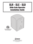
USAutomatic
STAR
High Quality Low Voltage
Vehicle Swing Gate Operator
Solar or AC Charged
STAR I
Single Swing Gate Operator
STAR II Dual Swing Gate Operator
Installation/Owners Manual
PROUDLY MADE IN THE USA
WWW.USAUTOMATIC.COM
INTRODUCTION
This operator is intended to be installed on vehicular Class I or Class II gates as defined by
UL 325. Maximum gate load not to exceed 300 pounds.
PLEASE READ THIS ENTIRE MANUAL CAREFULLY PRIOR TO INSTALLATION.
In doing so, along with performance of the installation in step-by-step order, you
will achieve optimal results. We strongly recommend that all installation and
service personnel pay particularly close attention to the safety systems section of
this manual and UL325. In addition to the current sense feature that is provided,
other safety devices are necessary to make each particular installation as safe as
possible to reduce the risk of personal injury and/or property damage. A trained
and authorized service technician or the factory should be consulted for assistance.
Cautions - Very Important
!
"
Do not attempt to enter the gate area while the gate is moving. Wait until
the gate comes to a complete stop.
"!
Operate the gate only when it is fully visible, free of persons or obstructions,
and properly adjusted.
"
Do not allow children to play in the area of the gate. Do not allow anyone
to ride on the gate.
"
Do not allow children to play with the remote control or any other
activation device.
"
Do not attempt to "beat the gate" while the gate is opening or closing.
This is extremely dangerous.
"
Test the current sense feature and all safety devices regularly to insure
correct operation.
"
Study the entire Safety Section, paying particularly close attention to the
Entrapment zones on pages 24-26 and be aware of these areas not only during
use but also during any adjustments to the unit.
"
"
Other Safety Standards
All control stations should be located at least 6 feet from any moving part
of the gate or operator.
Do not ever install any control device where a user will be tempted to reach
through the gate or fence to activate a gate.
© USAutomatic, Inc., 2000
All rights reserved. No part of this may be reproduced by any means
without the expressed written consent of the publisher.
-1-
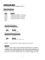
Table Of Contents
Page
Introduction......................................................................................1
Table of Contents.............................................................................2
General Requirements/Gate Qualifications & Applications ...........3
Importance of a Properly Designed Gate.........................................4
Mounting Site Review .....................................................................4
Parts Included List ...........................................................................5
Hinge Mount Tube Installation/Pull to Open ..................................6
Hinge Mount Tube Installation/Push to Open .................................7
Hinge Mount Tube Installation/Vertical Height..............................8
Preparation of Actuator....................................................................9
Actuator Installation........................................................................10
Mounting the Gate Bracket / Control Box Installation...................11
Master/Slave Dual Gate Wiring......................................................12
Charging Source Installation – Solar / AC .....................................13
Final Adjustments ...........................................................................14
Current Sense Adjust ......................................................................15
Limit Switches ................................................................................16
Circuit Board & Terminal Description ...........................................17
Function Jumper Settings................................................................18
Push to Open Modifications / Emergency Manual Release ...........19
Safety Section .............................................................................. 20-26
Troubleshooting ........................................................................... 27-30
Accessory Wiring Diagrams ........................................................ 31-37
Magnetic Wire Sensing Loops..................................................... 38-41
Warranty Statement .............................................................Back Cover
-2-
GENERAL REQUIREMENTS
General hand/tools such as combination wrenches, tape measure, level, clamps, etc. are
required. Your particular installation may require a drill or other hardware not provided.
Welding by a qualified welder is the recommended method of securing the linear actuator
mounts to the gate and hinge post. Bolt on brackets are an option, but they must be very
securely attached (i.e. carriage bolts with lock nuts and washers). Lag type bolts are not
recommended. Loose or unstable operator mounts will result in improper operation.
BATTERY REQUIRED FOR OPERATION (NOT INCLUDED).
We recommend a 12-volt deep cycle marine battery. The cable harness supplied
with the operator is designed for bolt type adapters such as ones found on most
marine batteries.
IMPORTANT CAUTIONS:
1. Do not perform any welding with the actuator cable plugged into the control
board or the battery connected. Serious damage to the control board and/or
battery will occur if attempted.
GATE QUALIFICATIONS/APPLICATIONS
GATE LENGTH/WEIGHT
This gate operator is rated for vehicular class I and class II swing gates up to 12 feet in
length and up to 300 pounds in weight as defined by UL325. If your gate exceeds either one
of these limits, please consult a qualified technician or the factory for alternative solutions.
(Example: convert one 20' gate into two 10' gates and use dual gate operators.)
Note:
The total gate opening normally cannot exceed 110 degrees.
Consult a service technician or the factory if greater opening is required.
GATE CYCLES PER DAY
Solar charged systems should not exceed 25 complete open/close cycles per day
without additional solar panels. This actuator type opener, whether AC or Solar
charged, should never be used in applications which exceed 100 complete open/close cycles
per day. Cycles can be decreased by holding the gate open during high cycle time periods. If
more cycles are required, a high traffic gate opener should be used.
-3-
IMPORTANCE OF A PROPERLY DESIGNED GATE
As a general rule a gate, which is to be automatically operated, must be stronger and
smoother than one, which will be manually operated. Since the gate is a major component
of the system, great care and concern must be given to the gate design.
A GATE OPERATOR CANNOT OVERCOME A POORLY DESIGNED GATE.
A. Does the gate swing smoothly without binds or excessive resistance? Swing gates
should swing level and plumb to prevent the operator from having to lift the gate open
or closed. Swing gates should not require a wheel to support them. Wheels usually
create drag, which will cause operator problems. A wheel is generally a sign of a
weak hinge system or a weak gate frame.
B. Is the gate frame of substantial strength without excessive weight? Will the frame
withstand normal wind load conditions without sway or vibration? Will the gate hit
the catch correctly without being hand-guided or lifted into the catch?
C. Are the hinges suited for the number of cycles expected per day? We recommend
bearing type hinges to reduce friction drag.
D. Will a reinforcement brace be required to attach the operator to the gate or does a
suitable cross member exist in the gate design?
If any of these problems exist, they must be corrected to achieve a reliable automatic gate
system.
MOUNTING SITE REVIEW
Installers should ask themselves these questions prior to installation and predetermine the
solution to any problems, which may occur.
A. Does sufficient space exist for mounting and future servicing of the operator and
control box?
B. Will the unit push the gate open to the outside or pull the gate open to the inside?
C. How will the actuator mounts be secured at the hinge and to the gate?
D. How will the control box be mounted securely enough to support the weight of the
battery and can it be located within 8 feet to prevent splicing of the actuator cable?
E. How will power be brought to the control box if AC charged?
F. How and where will the solar panel mount if solar charged so that optimum sunlight is
received?
G. How will exterior control wiring, if any, be brought to the control box?
H. Have all safety concerns been addressed? (See Safety Section Pgs. 20-26)
-4-
PARTS INCLUDED
*Actuator Arm with 8 foot of cable
Cabinet with Control Board
and Receiver
With Bracket
Battery
Charger
OR
SOLAR PANEL
*GATE BRACKET
2” x 2” x 12”
*TUBE
1 ¼” x 1 ¼” x 3 1/8”
*TUBE
*1-MANUAL RELEASE PIN
AND CLIP
*1-BOLT
½” X 2”
*2-LOCKNUT
½”
*3-WASHER
½”
*1-BOLT
½” X 4 ½”
2-PLACARDS
•
•
•
*For Star II quantity is doubled.
Additionally, 30’ of Master/Slave Actuator cable provided with the STAR II
Placards should be visible from inside and outside of gate.
NOTE: 12 Volt DC deep cycle marine battery required. (Not Included)
-5-
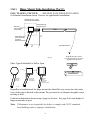
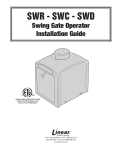
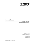
STEP 1
Hinge Mount Tube Installation (Part 1)
PULL TO OPEN / TOP VIEW
(SEE NEXT PAGE FOR PUSH TO OPEN)
(Left-handed installation shown. Reverse for right-handed installation)
Optional masonry column
Concrete fill recommended.
Dimensions from
hinge pivot point
Steel Post
4" min. diameter
1/4" thick min.
Gate
8"
Hinge Mount Tube
(cut as necessary
to achieve
dimensions shown)
6"
Gate Open Direction
Fig. 1A
Other Typical Methods For Pull to Open
Hinge Mount Tube must be
level in all directions for proper
alignment and operation.
LEVEL
Thick Plate
Thick Plate
Round post
saddle cut
tube for fit.
Thin wall post
add support to
prevent twisting.
LEVEL
Wood post
Bolt on.
1/2" carriage
bolts with
washers & locknuts.
Fig. 1B
Regardless of method used, the hinge mount tube should be very secure since the entire
force of the gate is directed to this mount. The post must be of adequate strength to resist
twisting as well.
Conform to dimensions shown at top of page in all cases. See page 8 to locate height of
hinge mount tube on post.
Note: USAutomatic is not responsible for failure to comply with UL325 standards,
local building codes or improper installations.
-6-
STEP 1
Hinge Mount Tube Installation (Part 1)
PUSH TO OPEN / TOP VIEW (SEE PREVIOUS PAGE FOR PULL TO OPEN)
(Left-handed installation shown. Reverse for right-handed installation)
Fig. 1D
Gate Open Direction
Optional masonry column.
Concrete fill recommended.
Dimensions from
hinge pivot point
Steel Post
4" min. diameter
1/4" thick min.
Gate
6"
Hinge Mount Tube
(cut as necessary to achieve
dimensions shown.)
8"
Hinge Mount Tube must be
Other Typical Methods for Pull to Open
level in all directions for proper
alignment and operation.
Thick Plate
LEVEL
Fig. 1E
Thick Plate
LEVEL
Thin wall post
add support to
prevent twisting.
Thick plates
Round post
saddle cut
tube for fit.
Wood post
Bolt on.
1/2" carriage bolts
with washers and locknuts.
Regardless of method used, the hinge mount tube should be very secure since the
entire force of the gate is directed to this mount. The post must be of adequate
strength to resist twisting as well.
Conform to dimensions shown at top of page in all cases. See page 8 to locate
height of hinge mount tube on post.
Note: USAutomatic is not responsible for failure to comply with UL325 standards,
local building codes or improper installations.
-7-
Hinge Mount Tube Installation (Part 2)
STEP 1
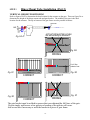
VERTICAL HEIGHT POSITIONING
Refer to figures 2B-2F to determine the best location for the actuator on the gate. Then use figure 2A to
determine the height of the hinge mount tube and gate bracket. The middle of the gate is the ideal
location for the actuator. The top or bottom of the gate frame are also possible locations.
gate bracket
5/8"
center line
Hinge
Mount
Tube
ACTUATOR MUST BE LEVEL!
Fig. 2A cable
Use above drawing for dimensions.
Fig. 2B
WRONG
2"x1/2" Bar
Added to Gate
Fig. 2C
Fig. 2D
CORRECT
CORRECT
Fig. 2F
Fig. 2E
WRONG
CORRECT
The gate bracket must be welded in an area that can withstand the full force of the gate.
Do not simply weld across a few pickets or bending of the pickets will occur.
Add a cross bar if necessary or weld the bracket to a piece of gate frame.
-8-
STEP 2
Prepare Actuator for Installation
Assemble the actuator to the extension tube as shown in figure 3A.
3 1/8"
extension
tube
1/2" x 2" Bolt
Actuator
Cylinder
1/2" locknut
(tighten firmly)
Fig. 3A
actuator cable
Now assemble the actuator to the gate bracket as shown in figure 3B
1/2" Manual Release Pin
1/2" Washer / Spacers
gate bracket
Fig. 3B
Bracket must pivot freely
-9-
STEP 3
Actuator Installation
Mount the actuator to the hinge mount tube as shown in Figure 4B.
Support the free end of the unit while mounting.
1/2" x 4 1/2" Bolt
Actuator
Cylinder
1/2" washers
Hinge
Mount
Tube
1/2" locknut
Tighten firmly. Do not overtighten.
Actuator must pivot freely.
Fig. 4B
actuator cable
Do not permanently mount the actuator upside down. Mount only as shown in the
illustrations.
NOTE: With Push to Open or right hand applications, the actuators may temporarily be
mounted upside down for ease of limit adjustments.
Open the gate to the desired OPEN position and block in place to secure the gate.
NOTE: The total opening cannot exceed 110 degrees. Consult a service technician or the
factory if greater opening is required.
Clamp the gate bracket to the gate at the previously determined point and weld to gate. Be
sure that your gate does not move while clamping. The location of the gate will set your
open position. The cylinder will be level if all steps were performed accurately.
Weld while clamped
Gate Secured in desired
OPEN position
WELD
Fig. 5A
-10-
STEP 3
Mounting of Gate Bracket (PUSH to Open Only)
Close the gate to the desired CLOSED position and block in place to secure the gate.
NOTE: The total opening can not exceed 110 degrees. Consult a service technician or the
factory if greater opening is required.
Clamp the gate bracket to the previously determined point and weld to gate. Be sure that
your gate does not move while clamping. The location of the gate will set your closed
position. The cylinder will be level if all steps were performed accurately.
Weld while clamped
Gate secured in desired
CLOSED position
Fig. 5B
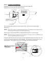
STEP 4
Mounting Control Box
Mount the control box at the determined location. The actuator cable is 8' in length. Keep
this in mind when choosing the location. If the cable must be lengthened, use proper wiring
and connectors in watertight boxes or control board damage may result (see drawing on page
12). If mounting holes must be drilled, be careful not to get drill shavings on the control
board. If welding, be careful not to damage the control board with excessive heat. After box
has been securely mounted, run the actuator cable into the control box through the hole in
the bottom tray and plug securely into control board.
NOTE: Push to open installations requires a USAutomatic adapter for each actuator.
See page 19 for more details.
Sprinkler
WRONG
Fig. 6A
Do not mount in areas by automatic sprinklers, or flood-prone areas. It is important that the
control board, control devices, and the battery compartment remain dry.
-11-
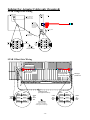
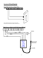
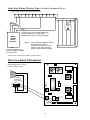
Splicing For Actuator Cable (only if required)
STAR I Single Gate Wiring
CONTROL BOX
Fig. 6B
Factory cable plug
cut off at 12" and
separate five wires.
Hinge
Post
Splice all 5
wires in water
tight box. Wires
should continue
as 5 separate
conductors.
Factory Cable
5 Conductor Cable
(Sold separately)
Cable
from
board
Red
Red
Black
Black
Green
Green
White
Orange
Cable
to
Junction Box
White
Orange
Cable
from
Control
Box
Use only approved
wire nuts or crimp
connectors. Connections
must be good and water tight.
Red
Black
Red
Black
Green
Green
White
Orange
White
Orange
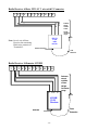
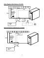
STAR II Dual Gate Wiring
Master Unit plug
Slave unit plug with
12" of cable
Slave Unit Cable
Cut off plug at 12"
for control box splice
Rain tight
junction box
DRIVEWAY
Cable
from
board
Red
Black
Red
Black
Green
Green
White
Orange
White
Orange
5 Conductor Cable
(30' supplied with Star II)
Cable
to
Slave
Unit
Cable
from
Control
Box
Use only approved
wire nuts or crimp
connectors. Connections
must be good and water tight.
-12-
Red
Black
Red
Black
Green
Green
White
Orange
White
Orange
Cable
to
Slave
Unit
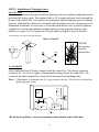
STEP 5 Installation of Charging Source
SOLAR PANEL
Locate and mount the solar panel bracket so that the panel faces southwest and maintains the
preformed 45-degree angle. The standard cable is 10' in length and must feed in through the
bottom of the control box. Pay attention to the distance when determining you’re mounting
location. Although the cable can be extended with watertight connectors, charging power is
diminished. Sometimes it is necessary to locate the panel farther away to achieve optimum
sunlight, but consider that optimum sunlight might not mean optimum charging if the
distance is to great. Use #16 gauge wire or larger and keep length as short as possible.
Assemble panel to bracket with supplied hardware.
Star I or Star II
BATTERY
+
red
black
West
North
WRONG
Do not place
Panel in
Shaded area
East
South
AC CHARGER
Locate and install the AC battery charger inside the control box. The charger requires a
receptacle for 110-volt AC supply: recommended location is inside the control box. The
receptacle should be installed by a licensed electrician per local building codes.
Note: USAutomatic recommends an AC surge protector on the 110-volt line be utilized in
lightning prone areas.
RECEIVER
CONTROL
BOARD
red
+
black
-
CHARGER
BATTERY
Fig. 7B
*Do not hook up battery wires from actuator/control board cable at this time.
-13-
STEP 6
Making Final Adjustments
In order to make final adjustments, a signal device such as a radio control should be used.
The control board is equipped with a pushbutton for this purpose. The button is designed to
give an open/close signal. The gate will open if closed or close if in the open position. A
signal in mid-travel will stop the gate.
•
If your unit was purchased with a radio receiver, it is important that you change the dipswitch code
settings on your receiver and on all of your transmitters. Please read the instructions found with your
transmitter or consult a dealer for assistance.
IMPORTANT NOTES
1.
Locate the actuator cable plug and be aware that you may need to disconnect it if the
cylinder over travels the desired stop points. You should be able to stop the motor
with a signal from your device without having to disconnect the plug, but in cases of
incorrect wiring, the plug can be used as an emergency power shut-off.
2.
Locate the sensitivity adjustment. We intentionally set the sensor at a highly
sensitive setting. This may need to be adjusted to achieve gate movement without
tripping the sensitivity circuit and causing the gate to reverse direction. See page 15
for details.
3.
Study the limit switch section and instructions on adjusting the limit switches prior
to battery hook up. See page 18 for details.
USAUTOMATIC STAR CONTROL
BOARD
Slave Actuator
CLOSE
0
10
10
0
Star II only
15 AMP
ADJUSTMENT
TIMER
SLAVE
CLOSE
LIMIT
Black Leads
OFF
ON
CLOSE TIMER
OPEN
LIMIT
+
Red Leads
PUSH
BUTTON
LED
MASTER
OPEN
LIMIT
RESET
MODE
Battery
CLOSE
LIMIT
LED
SINGLE
-
Master Actuator
15 AMP
DUAL
OPEN/CLOSE
PUSHBUTTON
+12V
OUTPUT GND
ENTRAPMENT
SIREN OUTPUT
RECEIVER
INPUT
GN
D
CLOSE
INPUT
GND
FREE
EXIT
SAFETY
OPEN GND STOP REVERSE
INPUT
GND +12V
If you have an understanding of the current sense feature, how to disconnect the actuator plug
in an emergency, and how to adjust the limit switches, then proceed to hook up the battery
leads and connect the plug to the board. The red battery lead goes to the positive + terminal
on the battery and the black lead goes to the negative - terminal on the battery.
-14-
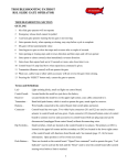
Current Sense Adjust
USAUTOMATIC STAR CONTROL
BOARD
CLOSE
SENSITIVITY
0
10 0
Adjusted by
Qualified Service Personnel
10
15 AMP
ADJUSTMENT
TIMER
SLAVE
CLOSE
LIMIT
5
OFF
ON
CLOSE TIMER
2
OPEN
LIMIT
8
0
10
PUSH
BUTTON
LED
MASTER
CLOSE
LIMIT
OPEN
LIMIT
LED
RESET
MODE
SINGLE
minimum reverse
sensitivity or
increase force
15 AMP
DUAL
Maximum reverse
Sensitivity or
decrease force
OPEN/CLOSE
PUSHBUTTON
+12V
OUTPUT GND
ENTRAPMENT
SIREN OUTPUT
RECEIVER
INPUT
GN
D
CLOSE
INPUT
FREE
EXIT
SAFETY
OPEN
GND INPUT GND STOP REVERSE
Reset
GND +12V
#!Adjust the current sensor so that the gate reverses when it hits a solid object. Do
not turn the dial beyond the stop points at 0 and 10.
#!If current sensor is activated twice before reaching a fully open or close position
the operator will stop operating and require a manual reset using the reset button
on the control board.
#!Remember if the gate reverses direction when operating without hitting and obstruction,
then minimizing sensitivity (increasing pressure) may be required. Do not increase any
more than necessary.
CAUTION: To reduce the risk of injury, USAutomatic strongly recommends the installation
of additional safety devices such as Photo Eye Sensors and Safety Edges.
Consult an authorized installing dealer or the factory for a complete explanation
of options and see the Safety Section of this manual on pages 20 to 26.
-15-
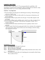
LIMIT SWITCHES
The limit switch adjustments are located on the side of the actuator. Remove the dust plug
to make adjustments. The normal settings from the factory allow for 12" of travel (approx.
70° opening). You will most likely have to adjust the limits for your installation. The
adjustments are labeled "Extend" and "Retract" on the dust plug. A 7/32” socket or nut
driver is required.
NOTE:
ALL ADJUSTMENTS SHOULD BE MADE IN THE MID TRAVEL (1/2 OPEN)
POSITION. DO NOT FORCE THE ADJUSTMENT SCREWS TO TURN
BEYOND THEIR MAXIMUM TRAVEL! FORCING WILL DAMAGE THE LIMIT
ASSEMBLY. REMOVE THE ADJUSTMENT TOOL AFTER EACH
ADJUSTMENT.
Side view of Actuator:
Actuator
Cylinder
Retract
Extend
actuator cable
The following will assist you. Shown below are adjustments for pull to open installations.
To extend more or close gate more.
Turn the extend adjust counter clockwise.
To extend less or close gate less.
Turn the extend adjust clockwise.
To retract more or open gate more.
Turn the retract adjust clockwise.
To retract less or open gate less.
Turn the retract adjust counter clockwise.
• Remember if the gate reverses direction without hitting an obstruction, then minimizing
sensitivity (increasing pressure) may be required. Do not increase any more than necessary.
-16-
Circuit Board & Terminal Description
USAUTOMATIC STAR CONTROL
BOARD
SENSITIVITY
0
CLOSE
10
10
0
15 AMP
ADJUSTMENT
TIMER
SLAVE
CLOSE
LIMIT
OFF
ON
CLOSE TIMER
OPEN
LIMIT
PUSH
BUTTON
LED
MASTER
CLOSE
LIMIT
OPEN
LIMIT
LED
RESET
MODE
SINGLE
15 AMP
DUAL
OPEN/CLOSE
PUSHBUTTON
+12V
OUTPUT
ENTRAPMENT
SIREN OUTPUT
GND +12V
TERMINAL
1
2
3
4
5
6
7
8
9
10
11
12
1
GND
RECEIVER
INPUT
2
3
4
GN
D
5
FREE
EXIT
SAFETY
OPEN
GND INPUT GND STOP REVERSE
CLOSE
INPUT
6
7
8
9
10 11 12
DESCRIPTION
+ 12 volt DC Output
Maximum current output 1.5 amp (1500 milliamps)
Common Ground Input
Receiver Input. (normally open)
Push button, radio control, keypad, etc.
Not used
Common Ground Input
Close input (normally open)
Not used
Common Ground Input
Free Exit/Open Input (normally open contacts)free exit loop input or any hold
open input such as a 7-day timer, telephone access unit, or maintain contact switch
(normally open contacts). These devices open the gate and will prevent the gate
from closing if the contact is maintained. Once the contacts have been released,
the gate can be closed with a closing signal device or the automatic close timer
feature.
Common Ground Input
Safety Stop (normally open). Stops a moving gate.
Safety Reverse (normally open) Secondary Entrapment Device Input
-17-
Function Jumper Settings
USAUTOMATIC STAR CONTROL BOARD
MADE IN USA
CLOSE
0
10
10
0
15 AMP
ADJUSTMENT
OFF
ON
TIMER
SLAVE
CLOSE
LIMIT
OFF
ON
CLOSE TIMER
OPEN
LIMIT
CLOSE TIMER
Factory Settings
PUSH
BUTTON
LED
MASTER
CLOSE
LIMIT
MODE
OPEN
LIMIT
LED
RESET
MODE
SINGLE
DUAL
SINGLE
15 AMP
DUAL
OPEN/CLOSE
PUSHBUTTON
+12V
OUTPUT
ENTRAPMENT
SIREN OUTPUT
GND
RECEIVER
INPUT
GND +12V
Factory settings are shown in bold italic type
S3
Automatic close timer circuit
ON
Timer to close is activated
OFF
Timer to close is disabled (Factory setting)
S2
Mode Select (SINGLE/DUAL)
SINGLE
DUAL
Single Gate Jumper Setting (Factory setting)
Dual Gate Jumper Setting
-18-
CLOSE
GND INPUT
FREE
EXIT
SAFETY
OPEN
GND INPUT GND STOP REVERSE
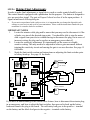
Push to Open Cable Modifications
Preferred Method
Cable Plug (sold separately)
Adapter
Plug
Connector
Male
Adapter Actuator
Plug
Cable
Connector
Plug
Female
Battery +
Battery To
Actuator
Control Board
Optional Method
Red
Black
Red/stripe
Black/stripe
Green
White
Orange
+ Battery
-- Battery
Red/stripe
Black/stripe
Green
White
Orange
Cut approximately 8” from
plug and reconnect with
suitable wire nuts or crimp
connectors as shown.
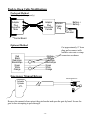
Emergency Manual Release
Manual Release Pin
Actuator
Cylinder
or
Remove the manual release pin at the gate bracket and open the gate by hand. Secure the
gate before attempting to pass through.
-19-
SAFETY SECTION
USAutomatic gate operators are manufactured to meet or exceed all UL325 Vehicular
Class I and Class II swing gate standards.
UL325 identifies four different classes of gate operators these classes are listed below:
Class I: Residential vehicular gate operator- A vehicular gate operator (or system) intended
for use in a home of one to four single family dwellings or a garage or parking area
associated therewith.
Class II: Commercial/General access vehicular gate operator- A vehicular gate operator (or
system) intended for use in a commercial location or building such as multi-family
housing unit (five or more single family units), hotel garages, retail store, or other
buildings servicing the general public.
Class III: Industrial/Limited access vehicular gate operator- A vehicular gate operator (or
system) intended for use in an industrial location or building such as a factory or
loading dock area or other locations not intended to serve the general public.
Class IV: Restricted Access vehicular gate operator- A vehicular gate operator (or system)
intended for use in a guarded industrial location or building such as an airport
security area or other restricted access locations not servicing the general public, in
which unauthorized access is prevented via supervision by security personnel.
Star I and Star II gate operators are intended to be installed as Class I or Class II vehicular
gate operators, and the maximum load of each gate leaf should not exceed 300 pounds with a
length not to exceed twelve feet.
SECONDARY ENTRAPMENT DEVICES
USAutomatic has designed all control boards with secondary entrapment device inputs and
Secondary safety devices must be installed with all installations. USAutomatic recommends
the use of the following devices and has provided herein instructions for the connection of
such devices.
NOTE:
USAutomatic recommends that these devices be CONNECTED after proper gate
installation and operation has been verified. Then connect one device and verify
proper operation before installing the next device.
-20-
SAFETY SECTION
Recommended Secondary Entrapment Devices
Contact Safety Devices:
Manufacturer - Miller Edge
Model
Description
MGR20
MGS20
ME120
MG020
ME123
ME110
ME111
3 sided protection fitted for 2” round frame
3 sided protection fitted for 2” square frame
1-sided protection attaches to flat surface
1-sided protection attaches to flat surface
1-sided protection attaches to flat surface
Non-Contact Safety Device:
Manufacturer – EMX Industries INC.
Model
Description
IRB-325
+12vdc Photo Eye
Siren (Entrapment Alarm) Devices:
Manufacturer – Signaling Systems
Model
Description
PZ
Piezoelectric siren, 128db +12vdc
NOTE:
For information about installation or applications, consult factory.
SERVICE
All gate operators require periodic checking and adjustments by a qualified
technician of the control mechanism for force (load), speed and sensitivity. All
external accessories and secondary safety devices must be checked. Secondary
safety devices need to be checked at least once a month for proper operation.
-21-
SAFETY SECTION
INSTALLATION
Install the gate operator when:
#!The operator is appropriate for the construction of the gate and the usage class is
correct for the installation.
#!All exposed pinch points are eliminated or guarded.
#!Only install on vehicle gates, pedestrians must be supplied with a separate access
opening.
#!The gate is installed in a location where enough space is supplied between adjacent
structures and the gate that when opening or closing the chance of entrapment is
reduced.
#!Swing gates shall not open into public access areas.
#!The gate is properly installed and swings freely in both directions. Do not over adjust
the sensitivity adjustment to compensate for an improper gate installation.
#!Locate all controls at least six feet away from the gate to eliminate the chance of the
person operating the gate from coming in contact with the moving gate. Do not install
external buttons, which can be used to operate the gate within the reach of children.
#!All placards must be installed one on each side of the gate visible in the gate area.
#!Contact sensors used for secondary entrapment safety devices and their wiring must
be installed in a manner protects them from mechanical damage.
#!Non-Contact sensors used for secondary entrapment safety devices must be located
so that the signal from the transmitter to the receiver is not interfered with by
adjacent structures. All exposed wiring must also be protected from mechanical
damage.
-22-
SAFETY SECTION
WARNING: TO REDUCE THE RISK OF INJURY OR DEATH
1.
2.
READ AND FOLLOW ALL INSTRUCTIONS
Never let children operate or play with gate controls. Keep remote control away
from children.
3.
Always keep people and objects away from the gate.
4.
NO ONE SHOULD CROSS THE PATH OF A MOVING GATE.
5.
Test gate operator monthly. The gate must stop and reverse directions upon
contacting a rigid object or when the secondary entrapment device is activated.
6.
After all adjustments have been made to the limit switches, sensitivity (current
sense) circuit, secondary entrapment devices and all other external devices
installed the safety devices must be checked again. Failure to adjust and retest
the gate operator can increase the risk of injury or death.
7.
Verify that the emergency release (manual release) pin can be easily removed.
This should only be checked when power is disconnected from the operator.
8.
KEEP GATES PROPERLY MAINTAINED. Read the user manual and have a
qualified service technician make repairs to the gate hardware.
9.
THE ENTRANCE IS TO BE USED BY VEHICLES ONLY. Pedestrians must
use a separate entrance.
10. SAVE THESE INSTRUCTIONS
-23-
SAFETY SECTION
All safety features required by UL 325 are incorporated in the capabilities of all
USAutomatic Control boards and should be utilized, including but not limited to, safety
edges, photo electric eyes, reverse sensing, and motion sensing.
Cautions - Very Important
Do not attempt to enter the gate area while the gate is moving. Wait until the gate
#!
comes to a complete stop.
Operate the gate only when it is fully visible, free of persons or obstructions, and
#!
properly adjusted.
Do not allow children to play in the area of the gate. Do not allow anyone to ride
#!
on the gate.
Do not allow children to play with the remote control or any other activation device.
#!
Do not attempt to "beat the gate" while the gate is opening or closing. This is
#!
extremely dangerous.
Test the current sense feature and all safety devices regularly to insure correct
#!
operation.
#!Study this entire Safety Section paying particularly close attention to the entrapment
zones shown below and be aware of these areas not on during use but also during
any adjustments to the unit.
ENTRAPMENT ZONES
Zone 1
Zone 2
Zone 3
Zone 4
Zone 5
The leading edge of the gate & catch post.
Between the gate and hinge post.
The arc of the gate or gate path.
The space between the gate when open and any obstruction such as fence, wall,
landscaping, etc.
(Not shown) the point where two bi-parting gates come together when closing.
This is similar to Zone 1.
-24-
SAFETY SECTION
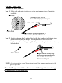
Remedies for Safety Concerns
Zone 1 Safety edge and photo electric eyes are the most common types of protection
available.
Reflector
Photo Eye Unit wire to
Secondary Entrapment Input
Catch Post
U-Shaped Safety Edge wire to
Secondary Entrapment Input
Zone 2 A safety edge may also be utilized here but the best remedy is to eliminate pinch
points when designing the hinges. Most injuries at this point result from
negligence, such as reaching through the hinge area or the gate to activate a button,
keyswitch, etc.
Catch Post
Single or dual safety edge
as required. Edges should
be wired to Secondary
Entrapment Input.
NOTE: All control stations should be located at least 6 feet from any moving part of the
gate or operator.
Never install any control device where a user will be tempted to reach through
the gate or fence to activate a gate.
-25-
SAFETY SECTION
Remedies for Safety Concerns
Zone 3
Safety edges are the best protection. A photo eye may also be used. For vehicle
traffic, magnetic vehicle detectors and wire sensing loops are preferred.
Reflector
Photo Eye Unit I wire to
Secondary Entrapment Input
Beam
Catch Post
Safety Edges on
bottom rail of gate.
Wire to Secondary
Entrapment Input.
U-Shaped
Safety Edge
Wired to Secondary
Entrapment Input
Reflector
Zone 4
Photo Eye Unit 2 wire to
Secondary Entrapment Input
Beam
This area is best protected with a photo eye wired to Safety reverse input
(Secondary Entrapment). The beam should be installed parallel to the gate in the
open position or along the obstructing wall or fence.
Zone 5
Wall or Fence Obstruction
B
E
A
M
Photo Eye Unit
Wire to Secondary Entrapment Input.
Reflector
Safety edges and photo eyes are the most common types of protection available.
Photo Eye Unit wire to
Secondary Entrapment Input
Reflector
Beam
Single or Dual Safety Edges wire to
Secondary Entrapment Input
Every installation is unique and it is the installer's responsibility to recognize and remedy all
safety concerns. Please consult a qualified dealer or the factory for a complete explanation
of the remedies shown above and additional tips pertaining to your installation.
-26-
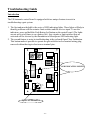
Troubleshooting Guide
Introduction
The USAutomatic control board is equipped with two unique features to assist in
troubleshooting a gate system.
1. The first and most helpful is the series of LED indicating lights. These lights will help to
identify problems with the actuator limit switches and the receiver input. To use the
indicators, press and hold the Push Button Led button on the control board. (The lights
are not active at all times to save battery life). Any circuits or limit switches that are
activated will be obvious by the illumination of the adjacent LED indicating light.
2. The second feature to assist in troubleshooting is the on board Open/Close Pushbutton.
This button makes it possible to operate the gate with the twelve terminal wiring plug
removed without having to short across terminal pins.
USAUTOMATIC STAR CONTROL
BOARD
CLOSE
0
10 0
10
15 AMP
ADJUSTMENT
TIMER
SLAVE
CLOSE
LIMIT
OFF
ON
CLOSE TIMER
OPEN
LIMIT
PUSH
BUTTON
LED
MASTER
CLOSE
LIMIT
OPEN
LIMIT
LED
RESET
MODE
SINGLE
15 AMP
DUAL
OPEN/CLOSE
PUSHBUTTON
+12V
OUTPUT GND
ENTRAPMENT
SIREN OUTPUT
RECEIVER
INPUT
GN
D
CLOSE
INPUT
GND +12V
Open/Close Pushbutton
-27-
FREE
EXIT
SAFETY
OPEN
GND INPUT GND STOP REVERSE
LED INDICATING LIGHTS
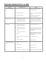
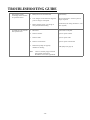
TROUBLESHOOTING GUIDE
SYMPTOM
1. Gate stops and reverses
direction in mid-travel.
2. Gate travels OK but after
closing, opens back up.
3. Gate doesn't move at all.
POSSIBLE CAUSE
REMEDY
a.
Current sense feature may be set too
sensitive.
Readjust- see page 15.
CAUTION: Sensitivity should be
sensitive enough to avoid injury.
b.
Gate operator is not plumb & level.
Remount hinge mount tube or gate
bracket.
c.
Gate or hinges are binding or are not
plumb and level.
Repair gate and readjust all actuator and
board settings.
d.
Low battery voltage.
Check battery/at least 12.5 volts DC.
e.
Control board is defective.
Replace control board.
f.
Shaft seal on actuator is binding due to
dryness. This usually occurs in colder
weather or first cycle in the morning.
Spray stainless actuator shaft with silicone
spray lube or spread a very light film of
all-purpose grease on shaft.
a.
Too much travel distance on closing cycle.
Readjust closing limit switch
See page 16.
b.
Actuator cable damaged or loose
connections.
Check actuator plug at control board and
cable for nicks or tears.
c.
Control board is defective.
Replace control board.
a.
Blown fuse
Replace if blown with 15-amp max.
b.
Loose or incorrect battery
connections or voltage.
Check battery connections, polarity
and voltage/at least 12.5 volts DC.
c.
Actuator cable damaged or
loose connection.
Check actuator plug at control board
and cable for nicks or tears.
d.
Actuator limit switch assembly
defective.
Replace or repair actuator.
e.
Control board is defective.
Replace control board.
f.
A control device such as a pushbutton, remote control, keyswitch,
etc. is shorted, which will lock up
the circuit board.
Remove signal wires from these devices one
at a time until board will activate.
-28-
TROUBLESHOOTING GUIDE
SYMPTOM
4.
Gate will not open with
remote control transmitter.
POSSIBLE CAUSE
REMEDY
a.
Improper code settings or wiring.
Check the code switches in the transmitter &
receiver. Verify that they are identical.
Check wiring of receiver.
b.
Weak transmitter battery.
Replace battery. LED light should illuminate
on remote.
c.
Poor antenna connection.
Check all connections and/or raise the
antenna to avoid metal objects.
5.
Gate activates open or
close for no reason.
a.
A shorted signal is coming into the
control board form an external
control device such as a remote
transmitter, pushbutton, key pad,
etc.
Check all transmitters and pushbuttons
for a stuck button. Remove signal wires
from control board one at a time until unit
returns to normal. Replace defective device
or wires.
6.
Automatic close timer will not
close the gate.
a.
An opening device such as a
button, keypad, phone unit, or
exit loop detector is shorted.
Remove each device from the system one at
a time until gate times out to close.
b.
A safety device such as a safety
loop detector or safety edge is
shorted.
Remove each device from the system one at
a time until gate times out to close. Use on
board indicating lights to assist in locating
the shorted circuit.
c.
A wire from one of these devices
is shorted.
Test cables by removing one at a time until
timer times out and gate closes. Use on
board indicating lights to assist in locating
the shorted circuit.
d.
Close timer jumper not properly installed or
missing.
Install jumper (see page 18)
e.
Defective control board.
Replace control board.
a.
Hinge mount tube dimensions are not
correct.
Remount hinge mount tube per instructions.
b.
Hinge post is weak.
Replace or reinforce post.
c.
Gate design is weak.
Replace or reinforce gate.
d.
Gate bracket is not mounted secure enough.
Remount bracket and reinforce surrounding
area.
7.
Gate jerks excessively when
activated and bounces during
cycle.
-29-
TROUBLESHOOTING GUIDE
8.
9.
Gate began to operate
increasingly slower and does
not operate at all now.
On a dual gate, only one unit
will open and close.
a.
Battery has one or more dead cells.
Replace battery.
b.
If AC charged, circuit breaker has tripped or
power to charger is interrupted.
Check circuit breaker. Check for power at
charger receptacle.
c.
Battery charging system (AC charger or
solar panel) is not functioning.
Consult factory for testing instructions. (Test
meter required).
a.
Blown fuse
Replace with 15-amp max.
b.
Defective actuator.
Repair or replace actuator.
c.
Defective cable.
Repair or replace cable.
d.
Defective control board.
Repair or replace control board.
e.
Master/Slave jumper not properly
installed or is missing.
Install jumper (see page 18)
Note:
Reverse actuator plugs on board
and actuator locations to
determine exact cause of problem.
-30-
Accessory Wiring Diagrams
Single Button Station to Open/Close
1
2
3
4
5
6
7
8
9
10 11 12
This configuration will give the gate an open signal
if the gate is closed and a close signal if the gate is open.
Radio Receiver Multi-Code 1099-40/Linear DRG-LV
1
2
3
4
5
6
7
8
9
10 11 12
antenna
gray
Height
Increases
range
gray
black
red
DRG-LV
Or
1099-40
12 volt
Radio
Receiver
Antenna mounts
outside of box
Coax cable
-31-
Radio Receiver Allister 9931-LV 3 wire with F Connector
1
2
3
4
5
6
7
8
9
10
11
12
black
white
red
Antenna
mount
outside
of box.
Height
increases
range.
9931-LV
12 volt
radio
receiver
Note: On a 4 wire Allister
Receiver the remaining
Black wire connects to
Terminal #2.
antenna connector
coax
extension
Radio Receiver Liftmaster 412 HM
1
2
3
4
5
6
7
8
9
10 11 12
Antenna
mount
outside
of box.
#1
#2 #3
#4
Height
Increases
range
412 HM
12-24
Receiver
Coax
extension
antenna
-32-
Radio Receiver Linear DRA-F 12 Volt
1
2
3
4
5
6
7
8
9
10 11 12
Two conductor wire from receiver
Antenna
mounts
outside
of box.
Silver conductor
Gold conductor
Com
NO
NC
Height
increases
Range
DRA-F
12 volt
Receiver
Coax
extension
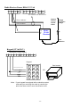
Keypad (12 Volt D.C.)
Momentary Contact Signal
1
2
3
4
5
6
7
8
9
10
11
12
Keypad
1
2
3
4
5
6
7
8
9
*
0
#
Card reader
Normally open relay contact
Common relay contact
12 volt -
OR
12 volt +
Note: If your keypad is equipped with a maintain contact
code and you are using the code to override the
auto close timer circuit, move the #3 wire to #9.
-33-
Telephone Access Unit Wiring Signal or Hold Open Signal
(Hold open circuit with timer to close override)
1
2
3
4
5
6
7
8
9
10 11 12
Normally open contacts from any device
such as a Free Exit Loop Detector,
maintain contact keyswitch, toggle switch,
7 day timer, telephone access unit, etc.
When the switch contacts close, the gate will
open and remain open until the contacts are
released. The close timer or any close signal
can now activate the gate.
Photo Eye Wiring for Secondary Entrapment Device
+12 volt Photo Eye
1
2
3
4
5
6
7
8
9
10 11 12
Orange/Blue
Shown for Secondary Entrapment device
For safety stop, move black wire to pin 11.
For free exit move black wire to pin 9.
Brown
Black
White- not used/cap off
*Stop circuit wiring also available, consult factory
Safety Edge Wiring (Wired Type) Secondary Entrapment Device
1
2
3
4
5
6
7
8
9
10
11
12
to Edge
*Stop circuit wiring also available, consult factory
-34-
Safety Edge Wiring (Wireless Type) Secondary Entrapment Device
Safety Edge Transmitter & Radio Receiver
1
2
3
4
5
6
7
8
9
10
11
12
GATE
Red
Black
Gray
Gray
Model
1099-40
Radio
Receiver
G
A
T
E
E
D
G
E
This receiver is for safety edge only.
Another receiver is required if a
transmitter is used to open the gate.
Note:
Use coax antenna to
locate antenna outside
of control box.
The transmitter battery will be
drained if the edge is
compressed continuously.
Design your gate catch to
avoid contact with the edge.
*Stop circuit wiring also available, consult factory
Siren Secondary Entrapment
USAUTOMATIC STAR CONTROL
BOARD
Output designed for +12vdc
Sirens less than 1 amp.
CLOSE
0
10 0
10
15 AMP
+12vdc
siren
ADJUSTMENT
TIMER
SLAVE
CLOSE
LIMIT
OFF
ON
CLOSE TIMER
Secondary
Entrapment
Siren Wiring
OPEN
LIMIT
PUSH
BUTTON
LED
MASTER
+12 volt
ground
CLOSE
LIMIT
OPEN
LIMIT
LED
RESET
MODE
SINGL
E
15 AMP
DUAL
OPEN/CLOSE
PUSHBUTTON
+12V
OUTPU
T
ENTRAPMENT
SIREN OUTPUT
GND +12V
-35-
GND RECEIVE
R
INPUT
GN
D
CLOSE
INPUT
FREE
EXIT
GND OPEN GN
INPUT
SAFETY
STOP REVERSE
Safety Magnetic Vehicle Detector 12 Volt DC
1
2
3
4
5
6
7
8
9
10
11
12
Yellow
White
Blue
To Earth
Ground or
Chassis
Ground
Black
Gray
Brown
Gray
Brown
Dual
Wire
Loops
Safety
Loop
Free Exit Magnetic Vehicle Detector 12 Volt DC
1
2
3
4
5
6
7
8
9
Yellow
White
Black
Blue
To Earth
Ground or
Chassis
Ground
Brown
Gray
Opening
Loop
-36-
10
11
12
Probe Type Free Exit Magnetic Detector 1
2
3
4
5
6
7
MFM-376 LC Kit
8
9
10
11
12
Power Input
N.C.
Probe buried
at drive.
COM.
{
See Mfgr.'s
Installation
Instructions
for Probe
Wiring
N.O.
}
D-376 Board
NOTE: This type of detector senses moving vehicles only. It should
be utilized as an opening device only. If used as a safety
device, the gate will close if the vehicle stops and possible
damage will result.
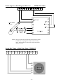
Seven-Day Timer to Hold Gate Open - TH800-12
1
2
3
4
5
6
7
8
9
10
11
12
#5
#4
#3
#2
#1
-37-
3:54
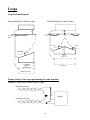
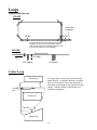
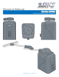
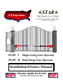
Loops
Loop Position Diagram
Single Swing Gate with 2 Loops
Dual Swing Gate with 2 Loops
5'
5'
Control
Box
Control
Box
Master Unit
Gate Path
Slave Unit
3' min.
Gate Path
Gate Path
3' m
7-8'
3' min.
in.
6' minimum
distance
between loops
6' minimum
6'
distance
between loops
Optional 3rd Loop
Optional 3rd Loop
Proper wiring of two loops performing the same function.
Example: Inside and Outside Safety Loops
Leads from 1st Loop
B
R
O
W
N
Leads from 2nd Loop
GRAY
-38-
Detector
Loops
Typical Loop Saw cut
TOP VIEW
Lead in slot
to operator
1/8" Min
1/4" Min
Corners should be cross-cut as shown for stress relief.
45 degrees is maximum turn angle allowed. Sawcut
width must be at least 1/8" for recommended wire. Lead
in slot must be at least 1/4" for twisted leads.
SIDE VIEW
Pavement Surface
1/4" min. backfill
1 1/2" depth
Siliconized
caulk
preferred
3/16" Sawcut
1/4" Sawcut
Center Loop
External Loop
5'
Control
Box
For larger gates, a loop can be placed directly
under the hate. A separate detector is required.
The loop will only be active when the gate is
fully open and will ignore the signal at all other
points. Consult a dealer or the factory for a
complete explanation.
Center Loop
Gate Path
3' m
in.
Internal Loop
-39-
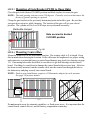
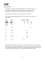
Loops
Loop Size Chart
The loop size is based on the width of the driveway. If the driveway is 14'
wide, the loop would be a 6'x6', the minimum. This is determined by
subtracting 4' off of each side of the drive, which would leave you 6'.
See chart below for number of turns per loop size, plus lead in.
The loop itself should contain between 90 & 125 feet of wire in the loop,
plus lead in.
Drive
Width
Loop
Size
Number of Turns
2
3
14' &
Under
6' x 6'
96'
16'
6' x 8'
112'
18'
6' x 10'
96'
20'
6' x 12'
108'
22'
6' x 14'
120'
24'
6' x 16'
132'
26'
6' x 18'
4
96'
The location of the loop is also important. If a loop is located too close to the gate, it
will detect the gate itself, giving false operation. If the loop is too far away from the
gate a small vehicle might not be detected. Loops should be approximately 5' from the
center line of a gate when closed. See Loop Position on previous 2 pages.
-40-
Loops
Other Loop Detector Facts
1. Always clean saw cuts thoroughly with water, air or brush to remove all debris prior to installing wire.
2. Recommended loop wire is TFFN #16 gauge stranded wire. It is available at electric supply
distributors.
3. No splices are permitted in the loop or loop leads. One continuous wire should be used.
4. Lead wires should be twisted a minimum of 4 twists per foot to eliminate false sensing. Twists should
begin at the edge of the loop and continue to detector.
5. Do not use metal or sharp objects to push the loop wire into the saw cut. The slightest nick or cut in the
insulation will cause the loop to ground out and malfunction. To test for shorts, use a megohmeter or
"Megger" between either loop lead and earth ground with both leads disconnected from the detector.
The resistance should be greater than 50 megohms.
6. Use siliconized caulk for backfill. Gray for concrete, black for asphalt. 25-Year life rating is preferred.
7. Never set adjacent loops on the same frequency. False activation will occur.
8. Almost all brands of detectors have an external or internal sensitivity adjustment. Usually the factory
setting is sufficient if internal adjust type. Be very careful and use extreme caution when decreasing
sensitivity.
9. Most false activations are caused by an improperly installed loop or a shorted loop. The loop should be
tested and validity determined before adjusting sensitivity. See # 5 above.
10. Most detectors used in the gate business are fail-safe. This means that if the loop fails, the gate will be
given a continuous signal. When power is disconnected from a detector, the signal output is also given.
11. ASB, or automatic sensitivity boost is now available on most detectors. This feature should be
activated if large truck or trailer traffic is likely.
To: USAutomatic
419 Southfork
Suite D
Lewisville, TX 75057
-41-
Star I
Star II
Limited 5 Year Warranty
USAutomatic
The Star Gate Operator is warranted to be free of defects in materials or workmanship for a period of 5 years
from date of purchase on the electronic control board and 12months on all other components. Any part,
parts, or complete unit found to be defective within this period will, at the manufacturer's option be repaired
or replaced at no charge if returned freight prepaid. New or factory rebuilt replacement parts are warranted
for the remaining portion of the original warranty period. The manufacturer will pay for standard ground
freight on the return of the repaired or replaced items under this warranty. The manufacturer will not be
responsible for field service or labor charges incurred in the removal or replacement of defective parts.
Furthermore, the manufacturer will not be responsible for incidental or consequential damages.
This warranty is in lieu of all other warranties expressed or implied and shall be considered void if damage
was due to improper use or installation, connection to an improper power source, or if caused by fire, flood,
lightning and other acts of nature, or by vehicles or vandalism.
This warranty gives you specific legal rights, and you may have other rights, which vary from state to state.
Some states do not allow limitations or exclusions of implied warranties so these may not apply to you.
Keep this portion for your records
Model:
Serial Number*:
Date of Purchase:
Purchased from:
CUT HERE
RETURN THIS PORTION TO:
USAutomatic
419 Southfork, Suite D
Lewisville, Texas 75057
Toll Free 1-888-204-0174
Model:
Serial #:
Name:
Address:
City:
Date of Purchase:
Purchased from:
State:
Zip:
*Serial number can be found by removing cover and looking on control board.