Download TROUBLESHOOTING PATRIOT RSL SLIDE GATE OPERATOR
Transcript
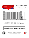
TROUBLESHOOTING PATRIOT
RSL SLIDE GATE OPERATOR
TROUBLESHOOTING SECTION
OUTLINE
1
My slide gate operator will not operate
2
Emergency release knob cannot be pulled
3
I can hear gate operator running but my gate is not moving:
4
Gate operates slowly when opening or closing, may stop before cycle is complete:
5
My gate will not automatically close:
6
Gate begins to open or close but stops and reverses after a couple of seconds.
7
Gate opening or closing stops and reverses direction and then stops and will not operate
8
Gate opens or closes correctly then immediately reverses direction:
9
Gate closes then opens back up in 10 seconds or more, auto close timer is on
10 Control board 15 amp fuse blows when open/close command is given.
11 Transmitter (Remote control) will not operate the gate.
12 Photo eye, safety loop or other safety accessory will not reverse the gate when closing.
13 Pressing the “RESET” button only, causes the gate to operate.
Terms and Definitions
Led -
Light emitting diode, small red lights on control board.
Control board-
Located inside the metal box just above the battery.
Receiver -
Located inside the metal box in the upper right corner, coax cable connected to it.
Transmitter -
Hand held push button, which is used to operate the gate, sends signal to receiver.
Harness -
Wire bundle connected to the control board, limit switch plate and motor.
Connector -
Control board has two types. Two white 8-pin connectors (X1 and X2) are used to connect
actuator to control board and one green 12-pin connector (J2) (located bottom center of control
board) to connect receiver and accessories to control board. Both are plug type and can be
disconnected (unplugged from control board) without disconnecting wires.
Dip Switches -
Small switches, which are located on the control board in two places. The primary set DS1 is
located in the upper left corner and the secondary set DS2 are located in the lower right corner
of the control board with functions listed beside each. See manual (page 15, 16) for more
information. Open position is off or switch not closed.
Push Buttons -
Three are located on the control board. “Open/Close command” used to operate the gate, “Led
Indicator” used to activate the leds and the “Reset” used to reset the control board after current
sensing twice before a limit is reached.
1
TROUBLESHOOTING PATRIOT
RSL SLIDE GATE OPERATOR
Limit Switch Plate –
Located on top of the operator, holds the two limit switches and also holds the limit nuts
in there adjusted position.
Limit Nut -
Two limit nuts are located on the top of the operator; the limit plate is spring loaded and must
be depressed before adjusting the limit nut. After limit nut has been adjusted make certain that
the limit plate fully engages the limit nut to keep it from rotating.
Gate Chain -
This is the long chain connected to the gate and travels through the operator.
Drive Chain -
This is the short chain that connects the gear motor to the manual release shaft.
1.
Slide gate operator will not operate:
STEP 1 Remove control box cover locate the “Open/Close Command” push button and press it to
operate the gate.
STEP 2 Press the “Reset” push button located above the open close command, then push the
“open/close command” push button to operate the gate.
STEP 3 When pressing the “open/close command” push button, listen for a clicking sound, if click is
heard then verify: The 15-amp fuse located on the control board is good if not replace it using
the spare located on the control board. Also check the dipswitches (3 and 4) for correct switch
settings based on where the harness is connected to the control board (Master or Slave). If
switches and fuse are good and clicking sound is heard the battery needs to be load tested to
determine its condition. Charge or replace depending on results.
STEP 4 Press and hold the “Led Indicator” push button and observe all of the red leds (see page 18 for
location):
a. If the two limit leds located below the actuator plug are both on the operator will not
operate. Verify that only one or no limit lights are on. If both limit lights are on adjust
limit nuts to the correct location.
b. If any of the leds in the lower left corner of the control board are on then this must be
corrected. Locate the accessory, which is activated, and repair or replace. Disconnecting
this device will allow the operator to work, without the disconnected accessory function.
STEP 5 Disconnect the green J2 connector. Once disconnected, press the “open/close command”
button. If gate operates go to step 4 b above.
STEP 6 Verify that DS1 switch 8 is off.
STEP 7 Call the factory for more information if the above steps have not worked.
2.
Emergency release knob cannot be pulled:
STEP 1 If the emergency release knob cannot be pulled first verify that it is not already pulled, by
trying to roll the gate. If gate will not move try to pull the emergency release knob while
agitating the gate (shake gate in direction of travel).
STEP 2 Emergency release knob that is difficult to pull represents something is in a bind. Check the
gate wheels and guide rollers. Verify the chain is on all the rollers and not twisted or over tight.
NOTE: DO NOT ATTEMPT TO MODIFY ANY SCREWS ON THE DRIVE SHAFT.
2
TROUBLESHOOTING PATRIOT
RSL SLIDE GATE OPERATOR
3.
I can hear gate operator running but my gate is not moving:
STEP 1 The most likely cause is the emergency manual release knob is pulled out. To correct open the
emergency release cover and push knob in, it may be necessary to roll gate while pushing the
knob in. The knob must be pushed in all the way and it may be necessary to remove the cover
to verify. When fully pushed in the space between the plastic safety disk and the shaft collar
should be about ¼”.
STEP 2 Other causes could be the gate chain is disconnected, the drive chain on the gear motor is
disconnected or one of the sprockets is freewheeling. Identify any of these by removing the
cover and inspecting and correct as necessary.
4.
Gate operates slowly when opening or closing, may stop before cycle is complete:
NOTE: When the gate is running slow the reason is low battery voltage, two things need to be
considered. Battery condition needs to be checked a load test is needed (replace or charge) and
determine what caused the battery to become discharged.
STEP 1 Determine which situation your operator falls into below:
Solar charged, ensure that you have a deep cycle battery installed and if accessories are
connected (keypads, loop detectors, any device powered by the battery) verify that the current
draw needed to power them does not exceed the charging power of the solar panel. Verify that
solar panel leads are connected to the battery correctly; panel is facing a southwest direction
and is not located in a completely shaded area. Inspect panel surface and wires for damage.
Test solar panel for correct voltage and current output, disconnect panel wires from battery and
using a DC voltmeter measure the dc voltage (should measure about 22 volts) and the dc
current (should read about 250 ma) in the peak sun period. If either, of these readings is
incorrect panel maybe defective.
If none of the above check bad then remove battery and have it load tested at a battery shop.
Replace if bad.
AC charged, ensure that you have a deep cycle battery rated at a minimum of 60 amp-hour
installed. If accessories are connected (keypads, loop detectors, any device powered by the
battery) verify that the current draw needed to power them does not exceed the charging power
of the charger. Verify that charger leads are connected to the battery correctly; charger is
connected to an approved 110 VAC receptacle. Inspect charger and wires for corrosion or
damage.
NOTE: The USAutomatic multi stage charger does not output any voltage when disconnected from the
battery, you cannot check charger by disconnecting from battery and measuring voltage output.
To check charger output disconnect from battery, measure battery voltage and note. Reconnect
charger and monitor battery voltage it should rise above the battery voltage noted above.
STEP 2 The charger has led indicators (lights) on the faceplate, observe the leds that are on or not and
refer to the troubleshooting directions furnished with the charger for definitions of different led
indicators.
STEP 3 If none of the above check bad then remove battery and have it load tested at a battery shop.
Replace if bad.
3
TROUBLESHOOTING PATRIOT
RSL SLIDE GATE OPERATOR
5.
My gate will not automatically close:
NOTE: If DS1 switch 1 is on and switch 2 is off then the gate should automatically close from any
position, but if switch 2 is also on the gate will only automatically close if the “open limit” led
(both “open limit” leds for dual gate) is on.
STEP 1 Locate the “Open/Close Command “ push button; press the button to verify that the gate will
close. If gate closes correctly then proceed to the steps below.
STEP 2 Verify that DS1 switch 1 is on. If not turn it on and recheck gate operation. If gate remains
open continue with step 3.
STEP 3 If your installation is a single gate, then only DS1 switch 3 or 4 can be on. If both are on the
gate will not automatically close. Turn off the one that is not being used and recheck gate
operation.
STEP 4 Locate the “Led Indicator” push button and depress and hold. While pushing the button inspect
the led indicators located just below the X1, X2 (master, slave) actuator plugs, note which leds
are on. Read note below.
NOTE: The two leds located below the X1, X2 actuator plug when on represent the closure of the limit
switch. If the left led is on then the gate should be in the open position, if the led on the right is
on then the gate should be in the closed position. If DS1 switch 9 (operating direction reverse)
is on then this is reversed. If the led for the open position is not on when the gate is fully
opened then the auto close will not work if DS1 switch 2 is on. The limit switches need to be
adjusted or DS1 switch 2 needs to be turned off. If gate still remains open go to step 5.
STEP 5 Locate the “Led Indicator” push button and depress and hold. While pushing the button inspect
the led indicators located on the control board (lower left corner) and note which ones are on.
If any leds are on disconnect the green J2 connector from the control board. Press the
“Open/Close Command “ push button to close the gate, and then press the button again to open
the gate fully and verify the automatic close is working.
STEP 6 If gate automatically closes correctly then the accessory connected to the J2 connector that is
activated (led is on) needs to be repaired.
6.
Gate begins to open or close but stops and reverses after a couple of seconds.
STEP 1 Remove gate operator cover and locate the Patriot control board. Locate the sensitivity
adjustment (see page 12) potentiometer located on the control board. The white center is
adjustable and needs to be turned in a clockwise direction.
STEP 2 Normally a setting of 5 will operate most gates; if your gate requires a setting above 6 there is a
good chance that your gate has a problem, which needs to be corrected. Possible causes are
incorrect alignment, something is interfering with the gate, guide rollers are binding, gate not
level or the gate chain is to tight. Identify and correct problem.
STEP 3 Other causes could be a safety device connected that is activated. Locate the “Led Indicator”
push button and press and hold operate the gate and note any leds that come on. If led comes on
identify the accessory connected to that input and correct the accessory problem.
STEP 4 Contact the factory for further information.
4
TROUBLESHOOTING PATRIOT
RSL SLIDE GATE OPERATOR
7.
Gate opening or closing stops and reverses direction and then stops and will not operate
STEP 1 This is most likely caused by an incorrect sensitivity adjustment. It could also be caused by an
obstruction located in the path of the gate.
STEP 2 Open the emergency manual release cover and pull the release knob. Then roll the gate fully
open and closed to verify that it is rolling freely. If gate is moving freely then the sensitivity
adjustment needs to be checked.
STEP 3 Remove the cover and locate the sensitivity adjustment on the control board. The Master and
Slave both need to be checked even if only one is being used. If the setting is above 6 verify
again that the gate is moving freely
8.
Gate opens or closes correctly then immediately reverses direction:
STEP 1 This is most likely caused by an incorrect limit switch adjustment, which is causing the gate to
travel to far and the operator to current sense. The limit switch adjustments are located on the
limit plate. Remove the gate operator cover and locate the limit plate and limit nuts.
STEP 2 Adjust the limit nut so that it is closer to the limit switch for the gate position being worked on.
This will cause the limit nut to contact the limit switch earlier, which will stop the gate earlier
than before. This needs to be done until the gate stops at the desired position. See note below.
STEP 3 It might be necessary to verify limit switch operation. To do this locate the “Led Indicator”
push button and hold in. Then depress the limit switch lever and observe the limit leds located
on the control board. The led should come on when the limit switch lever is depressed and the
“Led Indicator” push button is depressed.
NOTE: If DS1 switch 9 is turned on, then the open and close led lights are reversed. Open led
represents the closed position and the close led represents the open position.
STEP 4 If the led lights will not come on then contact the factory.
9.
Gate closes then opens back up in 10 seconds or more, auto close timer is on
STEP 1 This is most likely caused by an incorrect DS1 switch 9 setting. When standing on the inside of
the property and looking out of the gate which side of the drive is the gate operator installed
on? If it is on the right side then DS1 switch 9 should be in the off position. If operator is on
the left side of the drive then it should be in the on position.
STEP 2 If this does not correct the problem then the limit wires are connected incorrectly. Locate the
limit switches and the orange and white wires connected to them. The white wire should be
connected to the switch closest to the gate.
STEP 3 If the gate still operates incorrectly contact the factory.
10.
Control board 15 amp fuse blows when open/close command is given.
STEP 1 Fuses blow primarily for one reason, the gate cannot move. Causes might be something
keeping the gate from moving, the gate is trying to move in the wrong direction due to
incorrect limit switch setting or there might be a wiring problem.
STEP 2 See problem number 8 above and verify.
STEP 3 Press the “led indicator” push button and hold it in, observe the led lights and determine if the
open limit or close limit led is on. Then determine if the correct led is on for the gate position.
5
TROUBLESHOOTING PATRIOT
RSL SLIDE GATE OPERATOR
For example if the left led is on that is the open limit and the gate should be in the open
position. The right led represents the closed position.
See note under problem 7 above.
STEP 4 If the open limit led is on and the gate is closed if a command to operate is given the gate will
try to close more, which can blow a fuse. If the close limit led is on and the gate is opened a
command to operate will try to open the gate more, which can blow a fuse. In either case the
limit switches need to be adjusted and then the cause for them becoming misadjusted needs to
be determined.
STEP 5 Another possible cause is a bad brake on the gear motor. If the brake is on the motor cannot
turn and the fuse will blow. It is possible for low battery voltage to cause this so the battery
needs to be checked. If battery load tested good then contact the factory.
STEP 6 If the gear motor brake is the cause the brake can be disconnected to verify. Please contact
factory for further troubleshooting and return information.
11.
Transmitter will not operate the gate
STEP 1 Verify the 9-volt battery in the transmitter is good. Also verify that the dipswitches inside the
transmitter and receiver are set to match each other. Remove the receiver cover by squeezing
the sides and the switches are located inside. Remove the transmitter cover and locate the
switches.
STEP 2 Remove the gate operator cover and locate the Patriot control board. Locate the “Led
Indicator” push button and the “Push Button Input” led. Push the “led indicator” push button
and hold, then press the transmitter button and observe the “push button led”. The led should
come on while the transmitter button is depressed.
STEP 3 If the “Push Button Led” did not come on then make sure that the green J2 connector on the
control board is securely connected. Remove the receiver cover by squeezing the sides and the
switches are located inside.
STEP 4 If the “Push Button Input” led in step 1 did come on and the gate did not operate then locate
the “Open/Close Command” button located at the bottom center of the Patriot control board.
Press the “Open/Close Command” button and note gate operation.
STEP 5 If the gate did not operate in step 3 verify that the 15-amp fuse on the Patriot control board
adjacent to the actuator plug being used is not blown, (a fuse can be blown and look good)
replacing is the best way to verify fuse is good.
STEP 6 If the gate did not operate in step 3 and the fuse was good in step 4 then most likely a safety
accessory connected to the green J2 connector is active. Verify this by depressing the “Led
Indicator” push button and observe the leds located in the lower left corner of the Patriot
control board. If a light is on identify the accessory connected to the corresponding J2
connector pin and correct the problem.
STEP 7 Other causes are possible, both the open and close limit leds are on at the same time, if so
adjust limit switches. Control board could be defective; battery could be too weak to operate
the gate. Please call the factory for help identifying the cause.
6
TROUBLESHOOTING PATRIOT
RSL SLIDE GATE OPERATOR
12.
Photo-eye, safety loop or other safety accessory will not reverse the gate when closing or hold
the gate open
STEP 1 The first thing to check is the accessory wiring. The accessory needs power (+12vdc) wired to
battery positive terminal or to J2 pin 1 on the Patriot control board. It also needs ground, which
can be wired to the battery or to J2 pin 2 or 7 on the Patriot control board. The other two
connections are the “N/O and Common ground”. The common ground can be connected to the
battery or to J2 pin 2 or 7 on the Patriot control board. The N/O connection must be connected
to J2 pin 11 “Safety Loop / Reversing Edge Input”. If the accessory is connected as described
above it should reverse a closing gate or hold a gate open if the accessory is activated.
STEP 2 Now to determine if the accessory is working correctly and that the Patriot control board is
receiving the signal locate the “Led Indicator” push button and the “Safety Loop / Reversing
Edge Input” led (located in the lower left corner of the Patriot control board).
STEP 3 Press and hold the “led indicator” push button and observe the “Safety Loop / Reversing Edge
Input” led. Activate the accessory in question (if photo-eye break the beam) if the accessory is
working properly the led light should come on when the device is activated. If the device does
not turn on the led light then check wiring, J2 connector connection at the Patriot control
board. If wiring is good then the accessory is not operating correctly. Repair accessory and
retest.
STEP 4 If the “Safety Loop / Reversing Edge Input” led comes on and the gate does not reverse
direction when closing, call the factory for other possible causes and return information.
13.
Pressing the “RESET” button only, causes the gate to operate
STEP 1 This problem is probably due to a bad receiver. First locate the “Led Indicator” push button on
the Patriot control board. Then locate the “Push Button Input” led located in the lower left
corner of the Patriot control board.
STEP 2 Press the “Led Indicator” button and observe the “Push Button Input” led. If the light comes on
then the receiver relay is stuck closed and needs to be repaired or replaced.
STEP 3 If the “Push Button Input” led does not come on, call the factory for further troubleshooting
and return information.
7


