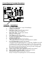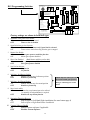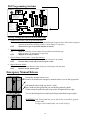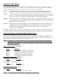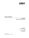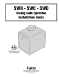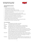
1
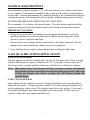
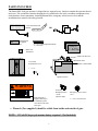
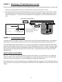
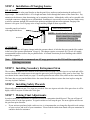
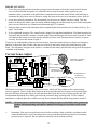
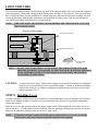
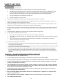
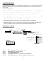
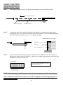
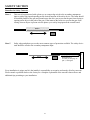
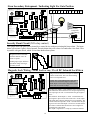
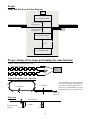
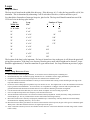
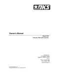
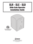
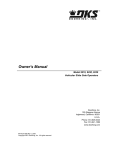
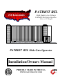
USAutomatic
PATRIOT RSL
High Quality Low Voltage
Vehicular Slide Gate Operator
Solar or AC Charged
PATRIOT RSL Slide Gate Operator
Installation/Owners Manual
PROUDLY MADE IN THE USA
WWW.USAUTOMATIC.COM
INTRODUCTION
This operator is intended to be installed on vehicular Class I or Class II gates as defined by
UL 325. Maximum gate load not to exceed 600 pounds.
PLEASE READ THIS ENTIRE MANUAL CAREFULLY PRIOR TO INSTALLATION.
In doing so, along with performance of the installation in step-by-step order, you
will achieve optimal results. We strongly recommend that all installation and
service personnel pay particularly close attention to the safety systems section of
this manual and UL 325. In addition to the current sense feature that is provided,
other safety devices are necessary to make each particular installation as safe as
possible to reduce the risk of personal injury and/or property damage. A trained
and authorized service technician or the factory should be consulted for assistance.
Cautions - Very Important
Do not attempt to enter the gate area while the gate is moving. Wait until
the gate comes to a complete stop.
Operate the gate only when it is fully visible, free of persons or
obstructions, and properly adjusted.
Do not allow children to play in the area of the gate. Do not allow anyone
to ride on the gate.
Do not allow children to play with the remote control or any other
activation device.
Do not attempt to "beat the gate" while the gate is opening or closing.
This is extremely dangerous.
Test the current sense feature and all safety devices regularly to insure
correct operation.
Study the entire Safety Section, paying particularly close attention to the
Entrapment zones on page 17-21 and be aware of these areas not only during
use but also during any adjustments to the unit.
Other Safety Standards
All control stations should be located at least 6 feet from any moving part
of the gate or operator.
Do not ever install any control device where a user will be tempted to
reach through the gate or fence to activate a gate.
© USAutomatic, Inc., 2001 rev N/C
All rights reserved. No part of this may be reproduced by any means
without the expressed written consent of the publisher.
1
Table Of Contents
Page
Introduction......................................................................................1
Table of Contents.............................................................................2
General Requirements/Gate Qualifications & Applications ...........3
Importance of a Properly Designed Gate.........................................4
Mounting Site Review .....................................................................4
Parts Included List ...........................................................................5
Operator Illustration/Description.....................................................6
Mounting Operator...........................................................................7
Mounting Operator /Post Mount Installation...................................8
Pad Mount Installation.....................................................................9
Mounting Chain Brackets/Connecting Chain.................................10
Installation of Charging Source ......................................................11
Installation of Secondary Entrapment Siren/Safety Placards .........11
Final Adjustments ........................................................................ 11,12
Current Sense Adjustment ..............................................................12
Limit Switches/Installing Cover .....................................................13
Circuit Board & Terminal Description ...........................................14
Function of Programming Switch Settings.................................. 15-16
Emergency Manual Release............................................................16
Safety Section .............................................................................. 17-21
Troubleshooting Introduction .........................................................22
Troubleshooting Guide ................................................................ 23-25
Accessory Wiring Diagrams ........................................................ 26-30
Magnetic Wire Sensing Loops..................................................... 31-32
Warranty Statement / Mail in Registration..........................Back Cover
2
GENERAL REQUIREMENTS
General hand/tools such as wrenches [7/16, 3/4], tape measure, level, clamps, chain cutter,
etc. are required. Your particular installation may require a drill, welder or other hardware
not provided. Concrete pad mounting by a qualified installer is the recommended method of
securing the operator. Post mounting is also acceptable, additional support may be needed.
BATTERY REQUIRED FOR OPERATION (NOT INCLUDED).
We recommend a 12-volt deep cycle marine battery. The cable harness supplied with the
operator is designed for bolt type adapters such as ones found on most marine batteries.
IMPORTANT CAUTIONS:
1. Do not test or operate this unit without first ensuring that all hardware is correctly
installed, limit nuts are securely locked in place with the limit locking plate and all
objects are clear of sprockets and chain.
2.
Do not perform any welding with the control board or the battery connected. Serious
damage to the control board and/or battery can occur if attempted.
3. Loose clothing can get caught in chain and sprockets resulting in bodily harm.
GATE QUALIFICATIONS/APPLICATIONS
GATE LENGTH/WEIGHT
This gate operator is rated for vehicular class I or class II slide gates up to 24 feet in length
and up to 600 pounds in weight as defined by UL325. If your gate exceeds either one of
these limits, please consult a qualified technician or the factory for alternative solutions.
Note:
High quality rollers with bearings will allow your gate to operate with minimal
drag (minimal friction) and will decrease the load on the gate operator. Many type
of slide gate designs exist. Choose a design that will decrease friction and
required torque.
GATE CYCLES PER DAY
Solar charged systems should not exceed 15 complete open/close cycles per day without
additional solar panels. This gate operator, whether AC or Solar charged, should never be
used in applications, which exceed 100 complete open/close cycles per day. Cycles can be
decreased by holding the gate open during high cycle time periods. If more cycles are
required, a high traffic gate opener should be used.
3
IMPORTANCE OF A PROPERLY DESIGNED GATE
As a general rule, a gate, which is to be automatically operated, must be stronger and
smoother than one, which will be manually operated. Since the gate is a major
component of the system, great care and concern must be given to the gate design.
A GATE OPERATOR CANNOT OVERCOME A POORLY DESIGNED GATE.
A.
B.
C.
D.
Does the gate slide smoothly without binds or excessive resistance? Slide gates
should slide level and plumb if possible to prevent the operator from having to pull
the gate up or down grade when opening or closing. Low quality wheels and rollers
usually create drag, which will cause operator problems. The use of high quality
bearing wheels and rollers are highly recommended.
Is the gate frame of substantial strength without excessive weight?
Will the frame withstand normal wind load conditions without sway or vibration?
Will the gate hit the catch correctly without being hand-guided or pushed into the
catch?
Are the bearings / wheels suited for the number of cycles expected per day?
Is the track area designed to keep dirt and rocks from obstructing the gate
movement?
If any of these problems exist, they must be corrected to achieve a reliable automatic gate
system.
MOUNTING SITE REVIEW
Installers should ask themselves these questions prior to installation and predetermine the
solution to any problems, which may occur.
A.
Does sufficient space exist for mounting and future servicing of the operator?
B.
*Will the unit open the gate by sliding to the left or the right? (see page 12 note #4)
C.
How will the chain brackets attach to the gate?
D.
How will the operator be mounted (on a pad or on a post)?
E.
How will the charging unit (AC or Solar) be brought to the control box?
F.
How and where will the solar panel mount if solar charged, so that optimum
sunlight is received?
G.
How will control wiring, if any, be brought to the control box?
H.
Have all safety concerns been addressed? (See Safety Section Pgs. 17-21)
NOTE: *Standing on the operator side of the gate, an operator installed to the left of the drive is a left
hand installation, an operator installed to the right is a right hand installation.
4
PARTS INCLUDED
The Patriot RSL slide gate operator is shipped in two separate boxes. One box contains the operator chassis
and cover. The second box contains charging device (with bracket for solar), secondary entrapment siren,
chain brackets, chain, transmitter, chain adjustment bolts, emergency release access cover and the
installation/user manual with safety placards.
5 watt Solar Panel and
Bracket
Chain Bracket
2 supplied
2”x6” (1/2” hole)
Battery
Charger
OR
2- ½” x 6” Chain Adjustment Bolts
4- ½ inch Nuts
CHAIN #41
3 – 10’ boxes
4 – Master links
1 – Multi-code
Transmitter
Multi code Receiver
Gear motor
UV treated
Polyethylene Cover
Patriot Control Board
4 – ¼” bolts
Operator Chassis
! WARNING
A MOVING GATE HAS THE POTENTIAL OF INFLICTING SERIOUS INJURY OR DEATH
Persons are to keep clear! The gate is able to be moved without prior warning.
Do not let children operate the gate or play in the gate area.
Persons are to operate the gate only when the gate area is in sight and free of people and obstructions.
Safety Placards 2
supplied. Placards to
be installed in plain
view and on both sides
of the gate.
Secondary
Entrapment Siren
+12vdc
2 push in snaps
Emergency release access
cover
1 – cover, screw and nut
• Placards (Two supplied) should be visible from inside and outside of gate.
NOTE: 12 Volt DC deep cycle marine battery required. (Not Included)
5
Operator Illustration and Descriptions
TOP VIEW
Gate
Output drive sprocket
Chain rollers
Gate bracket
Chain adjustment bolt
Limit Plate assembly
Limit adjustment cams
Radio receiver
Gear motor
Pillow block bearings
Safety disk
Emergency manual release locking bar
Emergency release knob
Illustration 1
FRONT VIEW
Drive chain/Gear motor
Emergency
release knob
Patriot control board
Emergency manual
Release locking bar
Cover bolt holes
4 plcs
Post mount sleeve
Illustration 2
REAR VIEW
Output drive sprocket
Battery
Compartment
Chain rollers
Chain
Pad mounting holes
Illustration 3
Note:
USAutomatic is not responsible for failure to comply with UL325 standards,
local building codes or improper installations.
6
Mounting Operator
NOTE: Do not mount in areas by automatic sprinklers, or flood-prone areas. It is important
that the control board, control devices, and the battery compartment remain dry.
Correct Installation
Incorrect Installation
GATE
GATE
Illustration 4
Illustration 5
Correct Installation
Incorrect Installation
Illustration 6
Illustration 7
2.00 inches
1.75 – 2.00 inches
3.25 - 3.50 inches
Post or pad mount
Correct dimensions for installed operator.
Illustration 8
7
Mounting Operator
PAD MOUNT:
The operator base has four predrilled holes and four access holes, which are covered with press in hole plugs. These holes
are sized to accommodate ½ anchor bolts and the plugged hole will accept a standard size ¾ inch socket. Keep the
operator parallel with the gate while securing. See illustrations 9,13 and 14 for dimensions.
POST MOUNT:
The operator base is equipped with a four-inch post receiver located on the bottom of the base. This receiver
will accept a square or round four-inch post. Keep the operator parallel with the gate and level while securing
in place. See illustration 10 for dimensions.
Set the operator in place (pad or post). Ensure that the chain bolts once installed will be properly aligned with the chain
rollers, see illustrations 4 – 8. Once alignment is verified secure operator in place using bolts for pad installation and
welding for post installation. Keep the operator parallel with the gate while securing in place.
Anchor bolt
access holes
(4 places).
Use with pad
mount or
post mount
with frame.
Reciever
Post
Receiver post located on
bottom of operator base.
Illustration 9
NOTE: Regardless of mounting method ensure that operator base does not extend into the
driveway area, where damage from traffic could occur.
STEP 1
Post Mount Installation
POST SPECIFICATIONS
Steel post is an optional mounting method. The type of post the operator is designed to handle is a 4 inch round or square
thick wall post. The operator can be installed directly onto the post or a steel frame can be constructed on the top of post.
If the method chosen is to construct a frame see dimensions in pad mount section (Illustrations 13,14) for bolt locations
and size. If the direct post mount option is chosen use the dimensions that follow to install, also consider that additional
bracing might be needed.
POST LOCATION TO GATE EDGE AND HOLE PREPARATION
GATE BOTTOM VIEW
4” steel post
(round or square)
8.75 inches
(measured from gate
edge to post edge.)
8.75 inches (measured from
operator edge to post edge)
When determining post location ensure
that the operator’s outer edge is a safe
distance away from the drive to avoid
damage from traffic.
See illustration 13 for operator base
overall dimensions.
Illustration 10
Post must be parallel to gate edge. Hole depth should be at least 36 inches and bell shaped to reduce operator movement to
a minimum. The post must be concreted in place
NOTE: Remember to mount the operator high enough above ground level so that the post
and operator can be welded securely.
8
STEP 1
Pad Mount Installation
CONCRETE PAD CONSTRUCTION
The mounting foundation must be very stable and of sufficient strength to prevent any movement. Mounting
site must be clear of flooding.
TOP VIEW PAD
Cross Section View
4 inch minimum
20” MINIMUM
24 inch minimum
Illustration 12
24 inch minimum
Illustration 11
28” MINIMUM
Illustration shown is for dirt surface area. Surface areas of different material may require different pad
dimensions.
When determining pad location
ensure that the operator’s outer
edge is a safe distance away
from the driveway to avoid
damage from traffic.
CONCRETE PAD LOCATION TO GATE
GATE TOP VIEW
20” MINIMUM
Maximum Distance between gate
edge and pad edge 2.0”
Optimum 1.75”
Illustration 13
28” MINIMUM
CONCRETE PAD ANCHOR BOLT LOCATION
Concrete pad top view measures 20” x 28”. This allows for 4” of concrete between the anchor bolts and the
outer edge of the pad. Use the drawing below to locate the four anchor bolts.
4 inches
TOP VIEW PAD
Gate Side
Locate anchor boltholes on gate
side corners using these dimensions.
4 inches
20” MINIMUM
12 inches
This hole is for ¾ electrical conduit
use dimensions shown.
3.3 inches
20 inches
1 inch
Illustration 14
28” MINIMUM
Note: USAutomatic is not responsible for failure to comply with UL325 standards, local
building codes or improper installations.
9
STEP 2 Mounting of Chain Brackets to Gate
With the operator securely mounted use the following procedure to locate and install gate brackets to gate ends.
1.
Install the chain adjustment bolt into the chain bracket as shown in illustration 15 below.
2. Slide the gate fully open. Using the diagram below locate the correct position for the gate bracket. Clamp
the bracket in place and repeat for gate in the fully closed position. Before welding gate brackets in place
refer to illustrations 4 – 8 to ensure correct installation. Once alignment is correct weld chain brackets in
place.
TOP VIEW (GATE FRAME 2”)
Outer nut
Chain Bracket
Inner nut
Chain Adjustment Bolt
½” Nut (2 plcs)
Illustration 15
Install chain adjustment bolts as
shown to allow for maximum
tension adjustment.
Illustration 16
STEP 3 Connecting Chain
Using the master links supplied connect one end of chain to one of the chain adjustment bolts. Use additional
master links to connect chain together as needed to route chain through the operator (See Illustration 3,16).
In most installations the chain will have to be cut to the desired length. To determine the desired chain length
loosen the chain adjustment bolts to allow for maximum adjustment (illustration 15). Pull the emergency release
knob to allow the chain to roll freely through the operator. Pull the chain to mate up with the remaining chain
adjustment bolt and mark link that needs to be cut. Once link is cut install master link and connect to chain
adjustment bolt.
CHAIN TENSION ADJUSTMENT
The outer ½ inch nut on the chain adjustment bolt adjust chain tension, it is important not to over tighten the
chain or premature wear will result. It is also important not to allow the chain to be to loose. Once the chain
tension is correct secure the inner ½ inch nut by tightening it against the chain bracket.
Once chain tension is correct and all nuts have been tightened push the emergency release knob back in place. It
may be necessary to roll the gate while pushing in on the knob, once the alignment is correct the knob will slide
in place.
10
STEP 4 Installation of Charging Source
SOLAR PANEL
Locate and mount the solar panel bracket so that the panel faces southwest and maintains the preformed 45degree angle. The standard cable is 10' in length and must feed in through the bottom of the control box. Pay
attention to the distance when determining you’re mounting location. Although the cable can be extended with
watertight connectors, charging power is diminished. Sometimes it is necessary to locate the panel farther away
to achieve optimum sunlight, but consider that optimum sunlight might not mean optimum charging if the
distance is too great. Use #16 gauge wire or larger and keep length as short as possible.
Panel facing southwest
Assemble panel(s) to bracket
with supplied hardware.
Red wire +
NOTE: Avoid shaded areas if possible.
Panels should face southwest
for optimum charging. See
explanation above for details.
Black wire Deep cycle
Battery
AC CHARGER
Locate and install the AC battery charger inside the operator chassis. A hole has been pre-punched for conduit
in the base of the operator (Illustration 14 page 9). The charger requires a receptacle for 110-volt AC supply;
recommended location is above the pre-punched hole. A licensed electrician per local building codes should
install the receptacle.
Note:
USAutomatic recommends an AC surge protector on the 110-volt line especially in
lightning prone areas.
STEP 5 Installing Secondary Entrapment Siren
The secondary entrapment siren connects to the control board (see page 30). This siren is very loud and will be
activated anytime the current sense circuit stops the gate twice prior to reaching a fully open or close limit. The
reset button on the control board (see page 12) must be pushed to turn off the siren, and reset the control board.
The frame has two pre-punched holes below the control board use these to secure the siren in place using the
two snap in plastic fasteners.
STEP 6 Installing Safety Placards
Mount safety placards on gate. Two signs are provided. Place one sign on each side of the gate where it will be
highly visible to anyone on either side of the gate.
STEP 7 Making Final Adjustments
In order to make final adjustments, a signal device such as a transmitter should be used. The gate will open if
closed or close if in the open position. A signal in mid-travel will stop the gate. The next signal would reverse
the gate from prior direction.
•
If your unit was purchased with a radio receiver, it is important that you change the dipswitch code settings
on your receiver and on all of your transmitters. Please read the instructions found with your transmitter or
consult a dealer for assistance.
11
IMPORTANT NOTES
1. Locate the power plug and be aware that you may need to disconnect it from the circuit board if the gate
over travels the desired stop points. You should be able to stop the motor with a signal from your
transmitter, blue reset button or the push button command located on the control board without having to
disconnect the plug, but in cases of incorrect wiring, the plug can be used as an emergency power shut-off.
2. Locate the sensitivity adjustment. We intentionally set the sensor at a highly sensitive setting. This may
need to be adjusted to achieve gate movement without tripping the current sensitivity circuit and causing the
gate to reverse direction. See current sense adjustment page 12 for details.
3. Study the limit switch section and instructions on adjusting the limit switches prior to battery hook up. See
page 13 for details.
4. Left or right hand operation. The control board is shipped for right hand installation, if left hand operation is
desired the dipswitch (DS1) number 9 located on the control board upper left corner must be turned on. This
will eliminate the need to rewire the operator and allow all auto close functions and accessories to operate
correctly. See note at the bottom of page 4.
If you have an understanding of the current sense feature, how to disconnect the power plug in an emergency,
and how to adjust the limit switches, then proceed to hook up the battery leads and connect the plug to the
board. The red battery lead goes to the positive + terminal on the battery and the black lead goes to the negative
- terminal on the battery.
Current Sense Adjust
USAutomatic
PATRIOT CONTROL BOARD
Timer
Sensitivity
5
5
0
10
0
CURRENT SENSE
ADJUSTMENT
DS1
SW-1
SW-2
SW-3
SW-4
SW-5
SW-6
SW-7
SW-8
SW-9
SW-10
10
0
TIMER TO CLOSE
ADJUSTMENT
DS1 SWITCH SETTINGS
O
N
1
2
3
4
5
6
7
8
9
10
5
MADE IN USA
FACTORY SETTINGS
AUTO CLOSE TIMER DISABLE
TIMER TO CLOSE WILL ACTIVATE ON LIMIT ONLY
MASTER GATE ENABLE BOTH ON FOR DUAL
SLAVE GATE ENABLE
NOT USED
SOFT START/STOP RETRACT ENABLE
SOFT START/STOP EXTEND ENABLE
STOP CIRCUIT ENABLE
OPERATING DIRECTION REVERSE
CUSTOM SOFTWARE ENABLE
15
15
OFF
ON
ON
OFF
OFF
OFF
OFF
OFF
OFF
OFF
Maximum Reverse
Sensitivity or
Decrease Pressure
LED INDICATOR
S2
J2 INDICATORS
1-
+12V OUT 1.5 AMP MAX
2-
COMMON GROUND
3-
PUSH BUTTON INPUT
4-
OPEN SAFETY EDGE
5-
CLOSE INPUT
6-
SECONDARY ENTRAPMENT DEVICE INPUT
78-
10
Adjusted by Qualified
Service Technician
Minimum Reverse
Sensitivity or
Increase Pressure
COMMON GROUND
STOP CIRCUIT INPUT N/C
9-
FREE EXIT / OPEN INPUT
10-
UNDER GATE / CENTER LOOP INPUT
11-
SAFETY LOOP / REVERSING EDGE INPUT
12-
MOTION DETECTOR INPUT
1
2
3
4
RESET
S1
Vehicular Gate Operator
Class I or Class II per UL325
Gate Weight Max. Load: 650 lbs.
1
2
3
4
5
6
7
8
9 10 11 12
J2
OPEN/CLOSE
COMMAND
Entrapment
Siren Output
C
O
M
M
O
N
G
N
D
S
O
L
O
N
O
I
D
L
O
C
K
C
O
M
M
O
N
G
N
D
M
A
G
L
O
C
K
S
E
C
U
R
I
T
Y
O SOLONOID LOCK ENABLE
N MAGNETIC LOCK ENABLE
SECURITY SHUNT ENABLE
MOTION DETECTOR ENABLE
RESET
S
H
U
N
T
The Patriot circuit board is equipped with a piezo buzzer, which will beep whenever the current sensing
circuit is triggered. There is a time delay between the beep and when the current sense circuit actually stops
the gate, this delay allows the effects of wind and other none fixed objects not to falsely stop the gate. The
recommended adjustment for a sliding gate would be to hear the beep on startup only. If a less sensitive
installation is required adjust the current sensor up. Do not turn the dial beyond the stop points at 0 and 10.
NOTE:
•
If current sensor is activated twice before reaching an open or closed limit switch position the
operator will stop operating and require a manual reset using the reset button on the control
board.
Remember if the gate reverses direction twice before reaching a limit switch the reset button on the
control board must be reset. If no obstructions were present then minimizing sensitivity (increasing
pressure) may be required. Do not minimize sensitivity any more than necessary.
12
LIMIT SWITCHES
The limit switch adjustments are located on the top shelf of the operator. Remove the cover from the operator to
make adjustments. The normal settings from the factory allow for about 15 feet of travel. You will most likely
have to adjust the limits for your installation. To adjust limits press down on the limit plate assembly, this will
release the limit plate from the limit adjustment cams and allow the cams to turn. Turn the limit adjustment
cam, which corresponds to the direction you want to adjust.
NOTE:
WHEN THE LIMIT ADJUSTMENT CAM DEPRESSES THE LIMIT SWITCH ACTUATOR
THE GATE WILL STOP.
Top view of the operator
Close Limit Cam Nut
Limit Plate Assembly
Limit Switches
Open Limit Cam Nut
Limit switch
actuator
NOTE:
DO NOT ADJUST THE LIMIT CAM NUTS PAST THE LIMIT SWITCH ACTUATOR
ARM.THIS MAY RESULT IN DAMAGE TO THE LIMIT SWITCH. ENSURE THE LIMIT
PLATE ASSEMBLY SNAPS INTO THE GROOVES ON THE LIMIT ADJUSTMENT
CAMS PRIOR TO OPERATION.
CAUTION: To reduce the risk of injury, USAutomatic strongly recommends the installation of additional
safety devices such as Photo Eye Sensors and Safety Edges. Consult an authorized installing
dealer or the factory for a complete explanation of options and see the Safety Section of this
manual on pages 17 to 21.
STEP 8 Installing Cover
Locate the emergency release access cover (round cover with USAutomatic logo), the shoulder screw and nut.
Install screw through emergency release access cover and install onto operator cover using the supplied nut.
Tighten nut securely.
Place the cover over the operator with the emergency release knob visible through the access hole. Secure in
place using the 4 – ¼” bolts and flat washers supplied. Slide the locking bar through slot cut below access hole
and secure to emergency manual release access cover, using a lock.
NOTE:
USAutomatic strongly recommends the Emergency manual release access cover be securely
locked in place using the locking bar and pad lock (pad lock not supplied)
13
Circuit Board & Terminal Description
Patriot Control Board
USAutomatic
MADE IN USA
PATRIOT CONTROL BOARD
Timer
Sensitivity
5
5
0
10
0
CURRENT SENSE
ADJUSTMENT
DS1
O
N
1
2
3
4
5
6
7
8
9
10
SW-1
SW-2
SW-3
SW-4
SW-5
SW-6
SW-7
SW-8
SW-9
SW-10
10
TIMER TO CLOSE
ADJUSTMENT
DS1 SWITCH SETTINGS
FACTORY SETTINGS
AUTO CLOSE TIMER DISABLE
TIMER TO CLOSE WILL ACTIVATE ON LIMIT ONLY
MASTER GATE ENABLE
BOTH ON FOR DUAL
SLAVE GATE ENABLE
NOT USED
SOFT START/STOP RETRACT ENABLE
SOFT START/STOP EXTEND ENABLE
STOP CIRCUIT ENABLE
OPERATING DIRECTION REVERSE
CUSTOM SOFTWARE ENABLE
15
15
OFF
ON
ON
OFF
OFF
OFF
OFF
OFF
OFF
OFF
LED INDICATOR
S2
J2 INDICATORS
1-
+12V OUT 1.5 AMP MAX
2-
COMMON GROUND
3-
PUSH BUTTON INPUT
4-
OPEN SAFETY EDGE
5-
CLOSE INPUT
6-
SECONDARY ENTRAPMENT DEVICE INPUT
78-
COMMON GROUND
STOP CIRCUIT INPUT N/C
9-
FREE EXIT / OPEN INPUT
10-
UNDER GATE / CENTER LOOP INPUT
11-
SAFETY LOOP / REVERSING EDGE INPUT
12-
MOTION DETECTOR INPUT
1
2
3
4
RESET
S1
Vehicular Gate Operator
Class I or Class II per UL325
Gate Weight Max. Load: 650 lbs.
1
2
3
4
5
6
7
8
9 10 11 12
J2
OPEN/CLOSE
COMMAND
Entrapment
Siren Output
C
O
M
M
O
N
G
N
D
O
U
T
P
U
T
+
1
2
V
S
O
L
O
N
O
I
D
L
O
C
K
C
O
M
M
O
N
G
N
D
M
A
G
L
O
C
K
S
E
C
U
R
I
T
Y
O SOLONOID LOCK ENABLE
N MAGNETIC LOCK ENABLE
SECURITY SHUNT ENABLE
MOTION DETECTOR ENABLE
S
H
U
N
T
TERMINAL DESCRIPTION
1
+ 12 volt DC Output.
*Maximum current output 1.5 amp (1500 milliamps)
2
Common Ground Input
3
Push Button Input. (normally open contacts)
Push button, radio control, keypad, etc.
4
Open Safety Edge (normally open contacts)
(Stops gate while opening)
5
Close Input (normally open contacts)
6
Secondary Entrapment Input (normally open contacts)
7
Common Ground Input
8
Stop Circuit Input (normally closed contacts)
* DS1 switch #8 must be on for stop circuit function to be enabled.
9
Free Exit/Open Input (normally open contacts)
Loop input or any hold open input such as a 7-day timer, telephone access unit,
or maintain contact switch (normally open contacts). These devices open the
gate and will prevent the gate from closing if the contact is maintained. Once
the contacts have been released, the gate can be closed with a closing signal
device or the automatic close timer feature.
10
Center Loop or Under Gate Loop Input (normally open contacts)
11
Safety Loop/Reversing Edge Input (normally open contacts)
12
Motion Detector Input (normally open contacts)
(Stops a closed gate from opening)(Active on close limit only)
14
DS1 Programming Switches
USAutomatic
MADE IN USA
PATRIOT CONTROL BOARD
Timer
Sensitivity
5
5
0
10
0
CURRENT SENSE
ADJUSTMENT
DS1
DS1 SWITCH SETTINGS
O
N
1
2
3
4
5
6
7
8
9
10
SW-1
SW-2
SW-3
SW-4
SW-5
SW-6
SW-7
SW-8
SW-9
SW-10
10
TIMER TO CLOSE
ADJUSTMENT
FACTORY SETTINGS
AUTO CLOSE TIMER DISABLE
TIMER TO CLOSE WILL ACTIVATE ON LIMIT ONLY
MASTER GATE ENABLE BOTH ON FOR DUAL
SLAVE GATE ENABLE
NOT USED
SOFT START/STOP RETRACT ENABLE
SOFT START/STOP EXTEND ENABLE
STOP CIRCUIT ENABLE
OPERATING DIRECTION REVERSE
CUSTOM SOFTWARE ENABLE
15
15
OFF
ON
ON
OFF
OFF
OFF
OFF
OFF
OFF
OFF
LED INDICATOR
S2
J2 INDICATORS
1-
+12V OUT 1.5 AMP MAX
2-
COMMON GROUND
3-
PUSH BUTTON INPUT
45-
OPEN SAFETY EDGE
CLOSE INPUT
6-
SECONDARY ENTRAPMENT DEVICE INPUT
7-
COMMON GROUND
8-
STOP CIRCUIT INPUT N/C
9-
FREE EXIT / OPEN INPUT
10-
UNDER GATE / CENTER LOOP INPUT
11-
SAFETY LOOP / REVERSING EDGE INPUT
12-
MOTION DETECTOR INPUT
1
2
3
4
RESET
S1
Vehicular Gate Operator
Class I or Class II per UL325
Gate Weight Max. Load: 650 lbs.
1
2
3
4
5
6
7
8
9 10 11 12
J2
OPEN/CLOSE
COMMAND
Entrapment
Siren Output
C
O
M
M
O
N
G
N
D
O
U
T
P
U
T
+
1
2
V
S
O
L
O
N
O
I
D
L
O
C
K
C
O
M
M
O
N
G
N
D
M
A
G
L
O
C
K
S
E
C
U
R
I
T
Y
O SOLONOID LOCK ENABLE
N MAGNETIC LOCK ENABLE
SECURITY SHUNT ENABLE
MOTION DETECTOR ENABLE
S
H
U
N
T
Factory settings are shown in bold italic type
1
Automatic close timer circuit enable
ON
Timer to close is activated
OFF
Timer to close is disabled
2
Open limit timer to close function
ON
Timer to close activates only if open limit is activated
OFF
Timer to close works from any point the gate is stopped
3
Master Gate Enable
ON
Master gate operator enabled to function
OFF
Master gate operator disabled
4
Slave Gate Enabled
(Both Master and Slave on for dual)
ON
Slave gate operator enabled to function
OFF
Slave gate operator disabled
5
Not Used at this time
No function
ON
OFF
No function
6
Soft Start / Soft Retract Enable
ON
Enables soft start/stop for Retract position
OFF
Disables soft start/stop
7
Soft Start / Soft Extend Enable
ON
Enables soft start/stop for extend position
OFF
Disables soft start/stop
NOTE: Soft start and stop are not
to be used on Slide gate operators.
Doing so will damage the control
board.
8
Stop circuit enable
ON
Allows for a stop button input to be utilized
* a normally closed pushbutton is required
OFF
Disables the stop button function
9
Operating Direction Reverse
ON
Push to Open or Left Hand Slider installation (See note bottom page 4)
OFF
Pull to Open or Right Hand Slider Installation
10 Custom Software Enable
ON
Enables Custom software if applicable
OFF
Disables Custom Software
15
DS2 Programming Switches
USAutomatic
MADE IN USA
PATRIOT CONTROL BOARD
Timer
Sensitivity
5
0
5
10
0
CURRENT SENSE
ADJUSTMENT
DS1
DS1 SWITCH SETTINGS
O
N
1
2
3
4
5
6
7
8
9
10
SW-1
SW-2
SW-3
SW-4
SW-5
SW-6
SW-7
SW-8
SW-9
SW-10
10
TIMER TO CLOSE
ADJUSTMENT
FACTORY SETTINGS
AUTO CLOSE TIMER DISABLE
TIMER TO CLOSE WILL ACTIVATE ON LIMIT ONLY
MASTER GATE ENABLE BOTH ON FOR DUAL
SLAVE GATE ENABLE
NOT USED
SOFT START/STOP RETRACT ENABLE
SOFT START/STOP EXTEND ENABLE
STOP CIRCUIT ENABLE
OPERATING DIRECTION REVERSE
CUSTOM SOFTWARE ENABLE
15
15
OFF
ON
ON
OFF
OFF
OFF
OFF
OFF
OFF
OFF
LED INDICATOR
S2
J2 INDICATORS
12-
+12V OUT 1.5 AMP MAX
COMMON GROUND
3-
PUSH BUTTON INPUT
4-
OPEN SAFETY EDGE
5-
CLOSE INPUT
6-
SECONDARY ENTRAPMENT DEVICE INPUT
78-
COMMON GROUND
STOP CIRCUIT INPUT N/C
9-
FREE EXIT / OPEN INPUT
10-
UNDER GATE / CENTER LOOP INPUT
11-
SAFETY LOOP / REVERSING EDGE INPUT
12-
MOTION DETECTOR INPUT
1
2
3
4
RESET
S1
Vehicular Gate Operator
Class I or Class II per UL325
Gate Weight Max. Load: 650 lbs.
1
2
3
4
5
6
7
8
9 10 11 12
J2
OPEN/CLOSE
COMMAND
Entrapment
Siren Output
C
O
M
M
O
N
G
N
D
O
U
T
P
U
T
+
1
2
V
S
O
L
O
N
O
I
D
L
O
C
K
C
O
M
M
O
N
M
A
G
L
O
C
K
G
N
D
S
E
C
U
R
I
T
Y
O SOLONOID LOCK ENABLE
N MAGNETIC LOCK ENABLE
SECURITY SHUNT ENABLE
MOTION DETECTOR ENABLE
S
H
U
N
T
Factory settings are shown in bold italic type
1
Solenoid lock enable / Gate in operation indicator
ON
Solenoid lock output energizes half second before gate begins to move and remains energized
until four seconds after reaching a limit (+12Vdc output 1.5 amp max)
OFF
Solenoid lock / gate in operation indicator is inactive
2
Magnetic lock enable
ON
Magnetic lock relay is active and will release half second before gate
begins to open (+12 vdc output 1.5 amp max)
OFF
Magnetic lock relay is inactive
3
Security Shunt Circuit Enable / Open Gate Indicator
ON
Security shunt circuit relay is active (closed circuit)(wire in parallel)
OFF
Security shunt circuit relay is inactive (open circuit)
4
Motion Detector Enable
ON
Activates motion detector input (if input is activated gate will not open)
OFF
Disables motion detector input
Emergency Manual Release
Emergency manual release cover
Remove lock and rotate emergency manual release cover to the up position.
Pull manual release knob out (about ¾ inch)
Once knob has been pulled the gate can then be pushed by hand.
If knob cannot be pulled the gate may need to be agitated left or right.
To reset the knob push in on knob and roll gate until knob snaps in place.
WARNING: Only insert hand into access hole as far as needed to grip the
release knob.
Trying to insert hand farther can result in injury.
16
SAFETY SECTION
USAutomatic gate operators are certified to UL325 Vehicular Class I and Class II slide gate standards.
UL325 identifies four different classes of gate operators. These classes are listed below:
Class I:
Residential vehicular gate operator- a vehicular gate operator (or system) intended for use in a
home of one to four single family dwellings or a garage or parking area associated therewith.
Class II:
Commercial/General access vehicular gate operator- a vehicular gate operator (or system) intended
for use in a commercial location or building such as multi-family housing unit (five or more single
family units), hotel garages, retail store, or other buildings servicing the general public.
Class III:
Industrial/Limited access vehicular gate operator- a vehicular gate operator (or system) intended for
use in an industrial location or building such as a factory or loading dock area or other locations not
intended to serve the general public.
Class IV:
Restricted Access vehicular gate operator- a vehicular gate operator (or system) intended for use in
a guarded industrial location or building such as an airport security area or other restricted access
locations not servicing the general public, in which unauthorized access is prevented via
supervision by security personnel.
The Patriot slide gate operator is designed and intended for use on Class I or Class II vehicular gate installations.
The maximum load of each gate leaf should not exceed 600 pounds with a length not to exceed twenty-four feet.
SECONDARY ENTRAPMENT DEVICES
USAutomatic has designed all control boards with secondary entrapment device inputs and secondary safety
devices must be installed with all installations. USAutomatic recommends the use of the following devices and
has provided herein instructions for the connection of such devices.
NOTE: USAutomatic recommends that these devices be CONNECTED after proper gate installation and
operation has been verified. Then connect one device and verify proper operation before installing
the next device. Ensure that power is disconnected from the control board prior to connecting any
wires to the control board.
Contact Safety Devices: Safety Edges
Manufacturer - Miller Edge
Description
Model
MGR20
3 sided protection fitted for 2” round frame
MGS20
3 sided protection fitted for 2” square frame
ME120
1-sided protection attaches to flat surface
MG020
1-sided protection attaches to flat surface
ME123
1-sided protection attaches to flat surface
Non-Contact Safety Device: Photo Eyes
Manufacturer – EMX Industries INC.
Model
Description
IRB-325
+12vdc Photo Eye
Manufacturer – Allen-Bradley
Description
Model
42GRU-9001
+12vdc Photo Eye
Entrapment Alarm Devices: Sirens
Manufacturer – USAutomatic
Model
Description
W12b-3
Piezoelectric siren, 108db +12vdc
NOTE:
For information about installation or applications, consult factory
17
SAFETY SECTION
INSTALLATION
a)
Install the gate operator only when:
1)
The operator is appropriate for the construction of the gate and the usage class of the gate,
2)
All openings of a horizontal slide gate are guarded or screened from the bottom of the gate to a minimum of 4 feet
(1.2m) above the ground to prevent a 2 ¼ inch (57.15mm) diameter sphere from passing through the openings
anywhere in the gate, and in that portion of the adjacent fence that the gate covers in the open position,
3)
All exposed pinch points are eliminated or guarded, and
4)
Guarding is supplied for exposed rollers.
b)
Only install on vehicular gates, pedestrians must be supplied with a separate access opening.
c)
The gate is installed in a location where enough space is supplied between adjacent structures and the gate so that when
opening or closing the chance of entrapment is reduced.
d)
The gate must be properly installed and work freely in both directions prior to the installation of the gate operator. Do not
minimize the sensitivity adjustment to compensate for an improper gate installation.
e)
Locate all controls at least six feet away from the gate to eliminate the chance of the person operating the gate from coming
in contact with the moving gate. Do not install external buttons, which can be used to operate the gate within the reach of
children.
f)
All placards must be installed one on each side of the gate and be visible in the gate area.
g)
For gate operators utilizing a non-contact sensor:
1)
2)
3)
h)
See instructions on the placement of non-contact sensors for each type of application,
Care shall be exercised to reduce the risk of nuisance tripping, such as when a vehicle, trips the sensor while the gate is
moving, and
One or more non-contact sensors shall be located where the risk of entrapment or obstruction exist, such as the
perimeter reachable by a moving gate or barrier.
For gate operators utilizing a contact sensor:
1) One or more contact sensors shall be located at the leading edge, trailing edge, and post mounted both inside and outside
of a vehicular horizontal slide gate.
2) A hardwired contact sensor shall be located and it’s wiring arranged so that the communication between the sensor and the
gate operator is not subjected to mechanical damage.
3) A wireless contact sensor such as one that transmits radio frequency (RF) signals to the gate operator for entrapment
protection functions shall be located where the transmission of the signals are not obstructed or impeded by building
structures, natural landscaping or similar obstruction. A wireless contact sensor shall function under the intended end-use
conditions.
WARNING: TO REDUCE THE RISK OF INJURY OR DEATH
1.
READ AND FOLLOW ALL INSTRUCTIONS
2.
Never let children operate or play with gate controls. Keep remote control away from children.
3.
Always keep people and objects away from the gate. NO ONE SHOULD CROSS THE PATH OF A MOVING GATE.
4.
Test gate operator monthly. The gate must stop and reverse directions upon contacting a rigid object or when the
secondary entrapment device is activated.
5.
After all adjustments have been made to the limit switches, sensitivity (current sense) circuit, secondary entrapment
devices and all other external devices installed the safety devices must be checked again. Failure to adjust and retest
the gate operator can increase the risk of injury or death.
6.
Verify that the emergency release (manual release) knob can be pulled easily. This should only be checked when
power is disconnected from the operator.
7.
KEEP GATES PROPERLY MAINTAINED. Read the user manual and have a qualified service technician make
repairs to the gate hardware.
8.
THE ENTRANCE IS TO BE USED BY VEHICLES ONLY. Pedestrians must use a separate entrance.
9.
SAVE THESE INSTRUCTIONS
18
SAFETY SECTION
All safety features required by UL 325 are incorporated in the capabilities of all USAutomatic Control boards
and should be utilized, including but not limited to, safety edges, photo electric eyes, reverse sensing, and
motion sensing.
Cautions - Very Important
!"Do not attempt to enter the gate area while the gate is moving. Wait until the gate comes to a complete stop.
!"Operate the gate only when it is fully visible, free of persons or obstructions, and properly adjusted.
!"Do not allow children to play in the area of the gate. Do not allow anyone to ride on the gate.
!"Do not allow children to play with the remote control or any other activation device. Do not attempt to "beat
the gate" while the gate is opening or closing. This is extremely dangerous.
!"Test the current sense feature and all safety devices regularly to insure correct operation.
Study this entire Safety Section paying particularly close attention to the entrapment zones shown below
!"
and be aware of these areas not on during use but also during any adjustments to the unit.
ENTRAPMENT ZONES
TOP VIEW
Zone 1
Zone 2
Zone 4
Zone 5
LEADING EDGE GATE VIEW
Gate Rollers
Fence
SIDE VIEW
Gate Leading Edge
Zone 3
Zone 1
Zone 2
Zone 3
Zone 4
Zone 5
The leading edge of the gate & fence post.
Between the gate and fence pocket.
The gate track and wheel.
The path the gate travels across the drive. (traffic area)
The path the gate travels when opening (back track gate area)
19
Zone 2
SAFETY SECTION
Remedies for Safety Concerns
Zone 1
Safety edges and photo electric eyes are the most common types of protection available.
Direction of Gate Travel
Contact Safety Edge
Zone 2
Photo Eye Beam
A safety edge may also be utilized here but the best remedy is to eliminate pinch points when
designing the gate. Most injuries at this point result from negligence, such as reaching through the
gate to activate a button, key switch, etc., or riding the gate open.
LEADING EDGE GATE VIEW
Gate Rollers
Zone 2
Fence
Gate Leading Edge
Zone 3
This area is best protected with proper gate construction and installation. Care must be taken to
minimize the exposed wheel to track area. A photo-eye or contact edge might also work in this area
depending on your gate construction.
SIDE VIEW
See page 18 under installation a. 3 and 4
for more information.
Zone 3
NOTE: All control stations should be located at least 6 feet from any moving part of the gate or operator.
Never install any control device where a user will be tempted to reach through the gate or
fence to activate a gate.
20
SAFETY SECTION
Remedies for Safety Concerns
Zone 4
This area is best protected with a photo eye or contact edge wired to the secondary entrapment
input or safety loop input depending on the desired function of the safety device. The beam should
be installed parallel to the gate and extend across the drive area to prevent the gate from closing or
opening on an object in the path of the gate. If the intent of the beam is to prevent the gate from
closing when an object is present wire the photo eye to safety loop input on the control board.
Zone 4
Zone 5
Safety edges and photo eyes are the most common types of protection available. The safety device
used should be wired to the secondary entrapment input.
GATE
Entrapment area
see safety section page 18
part a, 1 through 4.
O
B
J
E
C
T
Every installation is unique and it is the installer's responsibility to recognize and remedy all safety concerns.
Please consult a qualified dealer or the factory for a complete explanation of the remedies shown above and
additional tips pertaining to your installation.
21
SERVICE
All gate operators require periodic checking and adjustments by a qualified technician of the control
mechanism for force (load), speed and sensitivity. All external accessories and secondary safety
devices must be checked. Secondary safety devices need to be checked at least once a month for
proper operation.
Periodic checking is also advised for the following:
1.
2.
3.
4.
5.
6.
7.
Battery cells water level. (use distilled water if needed)
Wheels and gate rollers for wear and grease if necessary.
Bolts for correct tightness.
Inspect weld points for cracks or other defects.
Inspect wiring for cuts, nicks or other defects.
Inspect drive chain and sprockets for tension and wear. Adjust or replace as necessary.
Time to open or close the gate, this will be first indication of a battery or charging problem.
Troubleshooting Introduction
The USAutomatic control board is equipped with three unique features to assist in
troubleshooting a gate system.
1. The first and most helpful is the series of LED indicating lights. These lights will help to
identify problems with the limit switches and all control circuits. To use the indicators,
press and hold the LED indicator button on the control board. (The lights are not active at
all times to save battery life). Any circuits or limit switches that are activated will be
identified by the illumination of the adjacent LED indicating light.
2. The second feature to assist in troubleshooting is the current sense beeper. The beeper
will sound anytime the current sense circuit is activated. This is useful in detecting a
false reverse due to an improper or too sensitive current reverse setting or a gate that is
requiring excessive force to move.
3. The third feature to assist in troubleshooting is the on board open/close command
pushbutton. This button makes it possible to operate the gate with the twelve terminal
wiring plug removed without having to short across terminal pins.
Current Sense Beeper
USAutomatic
MADE IN USA
PATRIOT CONTROL BOARD
Timer
Sensitivity
5
5
0
10
0
CURRENT SENSE
ADJUSTMENT
DS1
O
N
1
2
3
4
5
6
7
8
9
10
LED indicator button
SW-1
SW-2
SW-3
SW-4
SW-5
SW-6
SW-7
SW-8
SW-9
SW-10
10
TIMER TO CLOSE
ADJUSTMENT
DS1 SWITCH SETTINGS
FACTORY SETTINGS
AUTO CLOSE TIMER DISABLE
TIMER TO CLOSE WILL ACTIVATE ON LIMIT ONLY
MASTER GATE ENABLE
BOTH ON FOR DUAL
SLAVE GATE ENABLE
NOT USED
SOFT START/STOP RETRACT ENABLE
SOFT START/STOP EXTEND ENABLE
STOP CIRCUIT ENABLE
OPERATING DIRECTION REVERSE
CUSTOM SOFTWARE ENABLE
15
15
OFF
ON
ON
OFF
OFF
OFF
OFF
OFF
OFF
OFF
Master Open limit
LED INDICATOR
S2
LED indicators for master /
Slave limits.
J2 INDICATORS
LED indicators J2
1-
+12V OUT 1.5 AMP MAX
2-
COMMON GROUND
3-
PUSH BUTTON INPUT
4-
OPEN SAFETY EDGE
5-
CLOSE INPUT
6-
SECONDARY ENTRAPMENT DEVICE INPUT
7-
COMMON GROUND
8-
Open/Close command
push button
Master Close limit
Slave Open limit
STOP CIRCUIT INPUT N/C
9-
FREE EXIT / OPEN INPUT
10-
UNDER GATE / CENTER LOOP INPUT
11-
SAFETY LOOP / REVERSING EDGE INPUT
12-
MOTION DETECTOR INPUT
1
2
3
4
RESET
S1
Vehicular Gate Operator
Class I or Class II per UL325
Gate Weight Max. Load: 650 lbs.
1
2
3
4
5
6
7
8
9 10 11 12
J2
OPEN/CLOSE
COMMAND
Entrapment
Siren Output
22
C
O
M
M
O
N
G
N
D
O
U
T
P
U
T
+
1
2
V
S
O
L
O
N
O
I
D
L
O
C
K
C
O
M
M
O
N
G
N
D
M
A
G
L
O
C
K
S
E
C
U
R
I
T
Y
S
H
U
N
T
O SOLONOID LOCK ENABLE
N MAGNETIC LOCK ENABLE
SECURITY SHUNT ENABLE
MOTION DETECTOR ENABLE
Slave Close limit
TROUBLESHOOTING GUIDE
SYMPTOM
1. Gate stops and reverses
direction in mid-travel.
*If this happens twice before
engaging either limit switch
the operator will shut down
and need to be reset.
2. Gate travels OK but after
fully opening or closing
reverses direction.
3. Gate doesn't move at all.
POSSIBLE CAUSE
REMEDY
a.
Current sense feature may be set too
sensitive. Listen for on board beeper to
verify. Beep indicates current sense
circuit activated.
Readjust- see page 12.
CAUTION: Sensitivity should be sensitive
enough to avoid injury.
b.
Gate operator is not plumb & level.
Remount operator or chain brackets. See
page 9.
c.
Gate or rollers are binding or are not
plumb and level.
Repair gate and readjust limits and board
settings.
d.
Control board is defective.
Replace control board.
a.
Too much travel distance on opening or
closing cycle. Causing current sense to
activate.
Readjust appropriate limit switch
See page 13.
b.
Wiring harness damaged or loose
Check actuator plug at control board and
cable for nicks or tears.
c.
Control board is defective.
Replace control board.
d.
Free exit false activating.
Depress LED push button and hold, watch
Led lights to determine which input is
activating, correct as necessary.
a.
Current sense circuit activated twice prior to
reaching fully open or close position.
Reset control board using reset button on
control board.
b.
DS1 switch settings
Verify switch 3 or 4 is on.
(Both 3 & 4 for a dual gate)
c.
Blown fuse
Replace if blown with 15-amp max.
d.
Limit switches misadjusted (if open and
close limit lights are on at the same time
control board will not operate).
Depress S2 and verify correct limit lights are
on (D1,D2,D3,D4) readjust if necessary
e.
Loose or incorrect battery connections or
voltage.
Check battery connections, polarity and
voltage/at least 12.5 vdc.
f.
Wiring harness damaged or has loose
connection.
Check actuator plug at control board and
cable for nicks or tears.
g.
Control board is defective.
Replace control board.
h.
A control device such as a push-button,
remote control, keyswitch, etc. is shorted,
which will lock up the circuit board.
Depress LED push button and hold, watch
Led lights to determine which input is
activating, correct as necessary.
23
TROUBLESHOOTING GUIDE
SYMPTOM
4.
Gate will not open with
remote control transmitter.
Press open/close push button
to verify control board is
good.
5. Gate activates open or close
for no reason.
6.
Automatic close timer will not
close the gate.
POSSIBLE CAUSE
a.
REMEDY
Check receiver wiring and receiver
b.
Use on board open/close command button, if
gate operates.
Improper code settings or wiring.
b.
Weak transmitter battery.
Replace battery. LED light should illuminate
on remote.
c.
Poor antenna connection.
Check all connections and/or raise the
antenna to avoid metal objects.
a.
A shorted signal is coming into the control
board from an external control device such
as a remote transmitter, pushbutton, key pad,
etc.
b.
Receiving signal from another transmitter
Check all transmitters and pushbuttons for a
stuck button.
Depress LED push button and hold, watch
Led lights to determine which input is
activating, correct as necessary.
Try changing transmitter and receiver
dipswitch settings.
a.
DS 1 switch setting
Check switch 1 to verify it is on.
c.
An opening device such as a button, keypad,
phone unit, or exit loop detector is shorted.
Depress LED push button and hold, watch
Led lights to determine which input is
activating, correct as necessary.
d.
A safety device such as a safety loop
detector or safety edge is shorted.
Depress LED push button and hold, watch
Led lights to determine which input is
activating, correct as necessary.
e.
DS 1 switch setting
f.
Primary or secondary entrapment circuit
activated
g.
Defective control board.
a.
Gate rollers are not correct.
Check rollers and track.
b.
Chain is incorrect.
Check chain and routing.
c.
Gate design is weak.
Replace or reinforce gate.
a.
Extreme bind on shaft
Gate needs to be moved by hand while
pulling on emergency release knob
simultaneously.
b.
Knob already pulled
Try and roll gate manually, if able to roll
push knob back in, gate needs to be
rolled while pushing in on the knob.
Check the code switches in the transmitter &
receiver. Verify that they are identical.
Ensure that switch 2 and 9 are set correctly
Activate gate using a manual device
(transmitter, exit probe etc.)
Replace control board.
7.
Gate jerks excessively when
activated and bounces during
cycle.
8. Emergency release knob
cannot be pulled.
24
TROUBLESHOOTING GUIDE
9.
Gate began to operate
increasingly slower and does
not operate at all now.
10. On a dual gate, only one unit
will open and close.
a.
Battery has one or more dead cells.
Replace battery.
b.
If AC charged, circuit breaker has tripped or
power to charger is interrupted.
Check circuit breaker. Check for power at
charger receptacle.
c.
Battery charging system (AC charger or
solar panel) is not functioning.
Consult factory for testing instructions. (Test
meter required).
a.
Blown fuse
Replace with 15-amp max.
b.
DS 1 switch settings
Verify switch 3 and 4 are in the on position
(Both 3 & 4 for a dual gate)
c.
Wiring to the slave gate is damaged.
25
Check wiring and correct
Accessory Wiring Diagrams
NOTE:
Ensure that battery power is disconnected from the control board before wiring accessories to
the control board.
Single Button Station to Open/Close
1
2
3
4
5
6
7
8
9
10 11 12
3 Button Station Wiring
Note: Program function switch DS1 #8 must be in the on position for stop button control
1
2
3
4
5
6
7
8
9
10 11 12
Open
Close
Stop
Ground
Seven Day Timer to Hold Gate Open – TH800-12
1
2
3
4
5
6
7
8
9
10 11 12
#1
#2
#3
#4
#5
8:00 am
Probe Type Free Exit Magnetic Detector
Wiring shown for MFM sensors Model # MFM-D376 LC
1
2
3
4
5
6
7
8
9
10 11 12
NOTE:
Power Input
N/C
N/O
Common
This type of detector senses moving vehicles only. It
should be utilized as an opening device only. If used as
a safety device, the gate will close if the vehicle stops
and possible damage will result.
D-376 Board
See mfgr.’s installation instructions
for probe wiring.
26
Radio Receiver Multi-Code 1099-40/Linear DRG-LV
1
2
3
4
5
6
7
8
9
10 11 12
Gray
Black
Gray
DRG-LV or 1099-40
12 volt
Radio receiver
8’ Coax extension
Red (+12vdc to receiver)
Radio Receiver Allister 9931-LV 3 wire with F Connector
1
2
3
4
5
6
7
8
9
NOTE: On 4 wire Allister receiver the
Remaining black wire connects
To terminal #2.
10 11 12
Black
9931-LV
+12v
Radio receiver
White
8’ Coax extension
Red
Radio Receiver Liftmaster 412 HM
1
2
3
4
5
6
7
8
9
10 11 12
#4
#3
#2
#1
412 HM
+12-24 v
Receiver
8’ Coax extension
DRA-F
+12 v
Receiver
8’ Coax extension
Radio Receiver Linear DRA-F 12 Volt
1
2
3
4
5
6
7
8
9
10 11 12
N/O
Com
Silver Conductor
ground
Gold Conductor
+12vdc
Two conductor wire from receiver
Albano Receiver: (Long Range) Single Channel
1
2
3
4
5
6
7
8
9
10 11 12
Pin 2 on receiver
Pin 1, 3 on receiver
Pin 8 on receiver
27
Antenna coax shield must be
connected to receiver pin 1
Keypad (12 Volt D.C.)
Card reader
(Momentary Contact Signal)
1
2
3
4
5
6
7
8
9
10 11 12
N/O relay
Common relay contact
-12 volt or ground
+12 volt
NOTE: The N/O relay can also
be wired to pin # 3. The keypad
would act exactly like a push
button transmitter when code was
entered. Maintain open pin # 9.
Keypad
1
2
3
4
5
6
7
8
9
*
0
#
or
Telephone Access Unit Wiring Signal or Hold Open Signal
(Hold open circuit with timer to close override)
1
2
3
4
5
6
7
8
9
10 11 12
Normally open contacts from any device such as a
Free Exit Loop, Maintain Contact Key switch, 7Day Timer, Telephone Access Unit etc.
When the switch contacts close, the gate will open
and remain open until the contacts are released.
The Close Timer or any close signal will only
operate after the switch contacts open.
Photo Eye Wiring for Secondary Entrapment Device
(+12 volt Photo Eye) Wiring shown for Allen Bradley Model # 42GRU-9001
1
2
3
4
5
6
7
8
9
10 11 12
Orange
Blue
Black
Brown
White-not used
Cap off
!" Stop circuit wiring also available, consult factory
Safety Edge Wiring (Wired Type) Secondary Entrapment Device
1
2
3
4
5
6
7
8
9
10 11 12
To Ground
To Edge
!"
Stop circuit wiring also available, consult factory
28
Safety Edge Wiring (Wireless Type) Secondary Entrapment Device
(Safety Edge Transmitter & Radio Receiver)
1
2
3
4
5
6
7
8
9
G
A
T
E
10 11 12
Gray
Gray
Black
Red
Wireless
Radio
Receiver
E
D
G
E
This receiver is for Safety edge only.
Another receiver is required if a
Transmitter is used to open the gate
Wireless transmitter
connected to gate
contact edge.
NOTE: Transmitter battery will be drained if
Contact edge on gate is depressed constantly.
!"Stop circuit wiring also available, consult factory
Safety Loop Magnetic Vehicle Detector 12 Volt DC
Wiring shown for Reno Model # BX-LP or BX-LP-SS detector
1
2
3
4
5
6
N/O or
Output A or B
Collector
7
8
9
(See Wiring Note Below)
10 11 12
Blue
Yellow
(not used SS model)
Safety Loop
Safety Loop
Safety Loop
Brown Gray
Gray
White (Earth or Chassis ground)
Black
Brown
Dual wired loops
Free Exit Loop Magnetic Vehicle Detector 12 Volt DC
Wiring shown for Reno Model # BX-LP or BX-LP-SS detector
1
2
3
4
5
6
7
8
9
N/O or
Output A or B
Collector
Wiring Note: When using the
SS model detector connect
detector pins 2 (“power –“)
5 and 9(“Output A, B Emitter”)
Together.
10 11 12
Blue
Yellow (not used SS model)
White (Earth or Chassis ground)
Open Loop
Brown
Connect the detector pin
corresponding to “output A or B
Collector” to the desired pin on
the control board.
Gray
Black
Safety Loop Magnetic Vehicle Detector 12 Volt DC
Wiring shown for Diablo Model # DSP-5LP detector
1
2
3
4
5
6
7
8
9
10 11 12
Loop
Loop
N/o
Relay
Common
Common
Power
+
29
Siren Secondary Entrapment / Indicating Light For Gate Position
Light illuminates anytime gate is not closed (4 second delay)
USAutomatic
MADE IN USA
PATRIOT CONTROL BOARD
5
5
0
10
SW-1
SW-2
SW-3
SW-4
SW-5
SW-6
SW-7
SW-8
SW-9
SW-10
3
6
7
8
9
10 11 12
FACTORY SETTINGS
AUTO CLOSE TIMER DISABLE
TIMER TO CLOSE WILL ACTIVATE ON LIMIT ONLY
MASTER GATE ENABLE
SLAVE GATE ENABLE BOTH ON FOR DUAL
NOT USED
SOFT START/STOP RETRACT ENABLE
SOFT START/STOP EXTEND ENABLE
STOP CIRCUIT ENABLE
OPERATING DIRECTION REVERSE
CUSTOM SOFTWARE ENABLE
OFF
ON
ON
OFF
OFF
OFF
OFF
OFF
OFF
OFF
15
15
+12vdc
siren
J2 INDICATORS
1-
+12V OUT 1.5 AMP MAX
2-
COMMON GROUND
3-
PUSH BUTTON INPUT
4-
OPEN SAFETY EDGE
5-
CLOSE INPUT
6-
SECONDARY ENTRAPMENT DEVICE INPUT
8-
5
LED INDICATOR
S2
7-
4
TIMER TO CLOSE
ADJUSTMENT
ADJUSTMENT
DS1 SWITCH SETTINGS
O
N
2
10
0
CURRENT SENSE
DS1
1
2
3
4
5
6
7
8
9
10
1
Timer
Sensitivity
COMMON GROUND
STOP CIRCUIT INPUT N/C
9-
FREE EXIT / OPEN INPUT
10-
UNDER GATE / CENTER LOOP INPUT
11-
SAFETY LOOP / REVERSING EDGE INPUT
12-
MOTION DETECTOR INPUT
1
2
3
4
RESET
S1
1
2
3
4
5
6
7
8
9 10 11 12
C
O
M
M
O
N
Vehicular Gate Operator
J2
Class I or Class II per UL325
OPEN/CLOSE
COMMAND
Gate Weight Max. Load: 650 lbs.
G
N
D
Entrapment
Siren Output
S
O
L
O
N
O
I
D
L
O
C
K
O
U
T
P
U
T
+
1
2
V
C
O
M
M
O
N
M
A
G
L
O
C
K
S
E
C
U
R
I
T
Y
G
N
D
O SOLONOID LOCK ENABLE
N MAGNETIC LOCK ENABLE
SECURITY SHUNT ENABLE
MOTION DETECTOR ENABLE
S
H
U
N
T
Security Shunt Circuit (N/O relay contact)
S
e
c
u
r
i
t
y
S
h
u
n
t
Secondary
Entrapment
Siren Wiring
+12 volt
ground
This option allows the gate to be activated by a control device without activating the home alarm. The home
alarm will activate if gate is forced opened. Security shunt relay will release 4 seconds after close limit. Wire
in parallel with gate switch, which is wired into home alarm system.
Program function switch DS2
switch #3 must be “ON” for
circuit to operate.
S
e
c
u
r
i
t
y
Leading edge of gate and fence
post shown using closed type
proximity switch.
S
h
u
n
t
Magnetic Lock Wiring / Stone Lock or any 12 volt DC Solenoid Lock/Siren
USAutomatic
Sensitivity
5
0
O
N
5
10
CURRENT SENSE
ADJUSTMENT
DS1
1
2
3
4
5
6
7
8
9
0
10
TIMER TO CLOSE
ADJUSTMENT
DS1 SWITCH SETTINGS
SETTINGS
SW-1
SW-2
SW-3
SW-4
SW-5
SW-6
SW-7
SW-8
SW-9
Mag lock and Solenoid lock outputs are labeled
On the circuit board. Take care when running
wires to avoid pinch areas.
MADE IN USA
Timer
PATRIOT CONTROL BOARD
FACTORY
AUTO CLOSE TIMER DISABLE
TIMER TO CLOSE WILLBOTH
ACTIVATE
ON LIMIT ONLY
ON FOR DUAL
MASTER GATE ENABLE
SLAVE GATE ENABLE
NOT USED
SOFT START/STOP RETRACT ENABLE
SOFT START/STOP EXTEND ENABLE
STOP CIRCUIT ENABLE
OPERATING DIRECTION REVERSE
15
15
OFF
ON
ON
OFF
OFF
OFF
OFF
OFF
OFF
NOTE: The corresponding DS2 switch must be
turned on for the desired output to function.
Both outputs can be used as long as the current
draw does not exceed 1.5 amps.
LED INDICATOR
S2
J2 INDICATORS
12-
+12V OUT 1.5 AMP MAX
COMMON GROUND
3-
PUSH BUTTON INPUT
4-
OPEN SAFETY EDGE
5-
CLOSE INPUT
6-
SECONDARY ENTRAPMENT DEVICE INPUT
7-
COMMON GROUND
8-
STOP CIRCUIT INPUT N/C
9-
1
2
3
4
FREE EXIT / OPEN INPUT
10-
UNDER GATE / CENTER LOOP INPUT
11-
SAFETY LOOP / REVERSING EDGE INPUT
RESET
S1
Vehicular Gate Operator
Class I or Class II per
UL325
Gate
Weight Max. Load: 650
lbs
1
2
3
4
5
6
7
8
9 10 11 12
J2
OPEN/CLOSE
COMMAND
Entrapment
Siren Output
C
O
M
M
O
N
G
N
D
O
U
T
P
U
T
+
1
2
V
S
O
L
O
N
O
I
D
L
O
C
C
O
M
M
O
N
G
N
D
M
A
G
L
O
C
K
S
E
C
U
R
I
T
Y
O SOLONOID LOCK ENABLE
N MAGNETIC LOCK ENABLE
SECURITY SHUNT ENABLE
MOTION DETECTOR
S
H
U
N
T
The Mag lock outputs +12vdc when the gate is on the closed
limit. When the control board receives an open input the mag
lock output goes to 0vdc .5 seconds before the gate begins to
move.
The Solenoid / Siren output is +12vdc 1 second before the
gate begins to open or close from a limit. The +12vdc output
will remain until a limit is reached plus a 4 second delay. The
control board will output the +12vdc 1 second before the gate
begins to move and will output +12vdc for 4 seconds after the
gate limit is reached. This also allows a siren or light to be
operated prior to movement.
The output is regulated to 1.5 amps by a autoreset able fuse.
30
Loops
Safety and Exit Loop Position Diagram
OUT
6 X 12 SAFETY LOOP
Loop located 4 feet
from gate track
GATE IN OPEN POSITION
Gate track
Loop located 4 feet
from gate track
Operator
6 X 12 SAFETY LOOP
8 feet
6 X 12 EXIT LOOP
Drive 20 feet
Proper wiring of two loops performing the same function
Example: Inside and Outside Safety Loops
Lead from first loop
Brown
Detector
Lead from second loop
Gray
Typical Loop Saw cut - top view
¼” minimum
1/8” minimum
Corners should be cross-cut as shown for
stress relief. 45 degrees is maximum turn
angle allowed. Sawcut width must be at
least 1/8” for recommended wire.Lead in
slot must be at least ¼” for twisted leads.
Lead in slot
to operator
Side view
Pavement srface
¼” minimum backfill
1 ½” Depth
Siliconized caulk
preferred
3/16” Sawcut
¼” Sawcut
31
Loops
Loop Size Chart
The loop size is based on the width of the driveway. If the driveway is 14' wide, the loop would be a 6'x6', the
minimum. This is determined by subtracting 4' off of each side of the drive, which would leave you 6'.
See chart below for number of turns per loop size, plus lead in. The loop itself should contain between 90 &
125 feet of wire in the loop, plus lead in.
Drive
Width Size
Loop
Size
14' & Under
6' x 6'
96’
16'
6' x 8'
112'
18'
6' x 10'
96'
20'
6' x 12'
108'
22'
6' x 14'
120'
24'
6' x 16'
132'
26'
6' x 18'
96'
28'
6' x 20'
104'
30'
6' x 22'
112'
32'
6' x 24'
120'
2
Number of Turns
3
4
The location of the loop is also important. If a loop is located too close to the gate, it will detect the gate itself,
giving false operation. If the loop is too far away from the gate a small vehicle might not be detected. Loops
should be approximately 5' from the centerline of a gate when closed. See Loop Position on previous 3 pages.
Loops
Other Loop Detector Facts
1.
2.
3.
4.
Always clean saw cuts thoroughly with water, air or brush to remove all debris prior to installing wire.
Recommended loop wire is TFFN #16 gauge stranded wire. It is available at electric supply distributors.
No splices are permitted in the loop or loop leads. One continuous wire should be used.
Lead wires should be twisted a minimum of 4 twists per foot to eliminate false sensing. Twists should begin at the edge of the
loop and continue to detector.
5. Do not use metal or sharp objects to push the loop wire into the saw cut. The slightest nick or cut in the insulation will cause the
loop to ground out and malfunction. To test for shorts, use a megohmeter or "Megger" between either loop lead and earth
ground with both leads disconnected from the detector. The resistance should be greater than 50 megohms.
6. Use siliconized caulk for backfill. Gray for concrete, black for asphalt. 25-Year life rating is preferred.
7. Never set adjacent loops on the same frequency. False activation will occur.
8. Almost all brands of detectors have an external or internal sensitivity adjustment. Usually the factory setting is sufficient if
internal adjust type. Be very careful and use extreme caution when decreasing sensitivity.
9. Most false activations are caused by an improperly installed loop or a shorted loop. The loop should be tested and validity
determined before adjusting sensitivity. See # 5 above.
10. Most detectors used in the gate business are fail-safe. This means that if the loop fails, the gate will be given a continuous signal.
When power is disconnected from a detector, the signal output is also given.
1 1 . ASB, or automatic sensitivity boost is now available on most detectors. This feature should be activated if large truck or trailer
traffic is likely.
32
PATRIOT RSL
USAutomatic
Limited 5 Year
Warranty
The PATRIOT RSL Slide Gate Operator is warranted to be free of defects in materials or workmanship for
a period of 5 years from date of purchase on the electronic control board and 12months on all other
components.
Any part, parts, or complete unit found to be defective within this period will, at the
manufacturer's option be repaired or replaced at no charge if returned freight prepaid. New or factory
rebuilt replacement parts are warranted for the remaining portion of the original warranty period. The
manufacturer will pay for standard ground freight on the return of the repaired or replaced items under this
warranty. The manufacturer will not be responsible for field service or labor charges incurred in the
removal or replacement of defective parts. Furthermore, the manufacturer will not be responsible for
incidental or consequential damages.
This warranty is in lieu of all other warranties expressed or implied and shall be considered void if damage
was due to improper use or installation, connection to an improper power source, or if caused by fire, flood,
lightning and other acts of nature, or by vehicles or vandalism.
This warranty gives you specific legal rights, and you may have other rights which vary from state to state.
Some states do not allow limitations or exclusions of implied warranties so these may not apply to you.
Keep this portion for your records
Serial Number*:
Model:
Purchased from:
Date of Purchase:
CUT HERE
RETURN THIS PORTION TO:
USAutomatic
118 Hillside
Lewisville, Texas 75057
Toll Free 1-888-204-0174
Model:
Serial #:
Name:
Address:
City:
Date of Purchase:
Purchased from:
State:
Zip:
* Serial number can be found by removing cover and looking on control board.