1
User’s Guide
For
Compulite R&D
Documentation Version 21
August 1999
Table of Contents
Part 1 - General
Chapter 1 Introduction .........................................................................................................1-1
Using this User’s Guide .................................................................................................... 1-3
Setting up Photon ........................................................................................................ 1-3
New users ................................................................................................................... 1-3
Common Terms ................................................................................................................ 1-3
Editing terms............................................................................................................... 1-3
Playback terms ............................................................................................................ 1-4
Text conventions...............................................................................................................1-4
Output Level Conventions................................................................................................. 1-4
Chapter 2 General Operation ................................................................................................ 2-1
The Editor Section ............................................................................................................ 2-2
F keys .........................................................................................................................2-2
Programming memories............................................................................................... 2-2
Editor color key........................................................................................................... 2-3
Editor error trapping.................................................................................................... 2-3
Clearing the editor ....................................................................................................... 2-3
A/B Crossfader .................................................................................................................2-3
Controllers........................................................................................................................ 2-5
Soft Keys.......................................................................................................................... 2-6
Assigning the default mode.......................................................................................... 2-6
Assigning a temporary mode........................................................................................ 2-6
Using the Soft Keys for playback control ..................................................................... 2-7
Color code for Soft Key LEDs ..................................................................................... 2-7
Examining controller assignments................................................................................ 2-7
General Master .................................................................................................................2-8
Menus .............................................................................................................................. 2-8
Accessing menus......................................................................................................... 2-8
Exiting the menu mode.............................................................................................. 2-10
Text & the Alphanumeric Keyboard................................................................................ 2-10
A page of text............................................................................................................ 2-10
Erasing text ............................................................................................................... 2-11
Using the text keyboard for programming .................................................................. 2-11
Getting Help ................................................................................................................... 2-12
System Status ................................................................................................................. 2-12
Color key for System Status....................................................................................... 2-12
What to do in case of disconnection ........................................................................... 2-12
Disabling a device ..................................................................................................... 2-13
Chapter 3 Displays ............................................................................................................... 3-1
Overview.......................................................................................................................... 3-2
Display Control ................................................................................................................3-2
Display Formats................................................................................................................3-2
Selecting display formats............................................................................................. 3-3
The Stage Display............................................................................................................. 3-3
Customizing the display format ................................................................................... 3-3
The Playback Display ....................................................................................................... 3-4
Messages and Commands ................................................................................................. 3-4
Output Color Key.............................................................................................................. 3-5
The X-Fade Exam Display ................................................................................................ 3-5
Exam Displays..................................................................................................................3-5
ii
Chapter 4 Quick Start........................................................................................................... 4-1
Setting Up Photon ............................................................................................................ 4-2
Configuring Photon .......................................................................................................... 4-2
Patching ........................................................................................................................... 4-3
Patching dimmers to channels ..................................................................................... 4-3
Patching scrollers to channels...................................................................................... 4-3
Selecting channels & assigning intensity ........................................................................... 4-4
Selecting scrollers & assigning frames .............................................................................. 4-4
Programming Memories ................................................................................................... 4-4
Playback Memories on A/B .............................................................................................. 4-5
Playback Chasers.............................................................................................................. 4-5
Recording a Show File...................................................................................................... 4-5
Part 2 - Basic Editing
Chapter 5 Selecting and Editing Channels & Scrollers.......................................................... 5-1
Selecting Channels ........................................................................................................... 5-2
Selecting a single channel............................................................................................ 5-2
Selecting nonsequential channels................................................................................. 5-2
Selecting a range of channels....................................................................................... 5-3
Reselecting the last channel selection .......................................................................... 5-3
Grabbing channels in the editor and on stage ............................................................... 5-4
Assigning Intensity Levels ................................................................................................ 5-4
Dimmer level assignments using @ ............................................................................. 5-4
Repeating an intensity assignment ............................................................................... 5-5
Releasing a Channel from the Editor ................................................................................. 5-5
Selecting and Editing Scrollers ......................................................................................... 5-6
Color code for scroller channels .................................................................................. 5-6
Assigning frame values .............................................................................................. 5-7
Chapter 6 Programming Memories....................................................................................... 6-1
Programming Memories ................................................................................................... 6-2
Displays ........................................................................................................................... 6-3
Programming with Channels............................................................................................. 6-3
Programming with Scrollers.............................................................................................. 6-4
Using the Copy Function .................................................................................................. 6-4
Copying channel intensities from the editor ................................................................. 6-4
Copying channel intensities from a memory................................................................. 6-5
Copying scroller frames from the editor....................................................................... 6-5
Copying scroller frames from a memory...................................................................... 6-5
Programming a Blackout Cue ........................................................................................... 6-6
Sequential Memory Programming..................................................................................... 6-6
Using the Call Function .................................................................................................... 6-7
Using Call to store the current lighting state................................................................. 6-7
Using Call and controller assignments ......................................................................... 6-8
Merging selected output sources .................................................................................. 6-8
Editing after Call......................................................................................................... 6-9
Calling A/B................................................................................................................. 6-9
Call and the General Master ........................................................................................ 6-9
Examining Memories & Channels................................................................................... 6-11
Examining memories................................................................................................. 6-11
Examining channels .................................................................................................. 6-12
Text for Memories.......................................................................................................... 6-14
Programming in Blind Mode........................................................................................... 6-14
Resetting the blind editor........................................................................................... 6-15
Fade Times..................................................................................................................... 6-15
Assigning fade times while programming memories .................................................. 6-16
iii
Assigning fade times to a range of memories ............................................................. 6-16
Assigning fade times to non-sequential memories ...................................................... 6-17
Modifying time assignments...................................................................................... 6-17
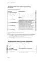
Converting Memories to Editor Groups ........................................................................... 6-18
Converting a memory when the editor is empty.......................................................... 6-18
Converting a memory to a group when the editor is active.......................................... 6-19
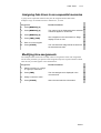
Inserting a Memory......................................................................................................... 6-20
Memory Operations in the Editor ....................................................................................6-20
Renaming and exchanging memories ......................................................................... 6-20
Copying memories ................................................................................................... 6-21
Erasing memories...................................................................................................... 6-22
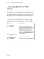
The Memory Operations menu........................................................................................ 6-23
Renaming memories.................................................................................................. 6-23
Copying a memory .................................................................................................... 6-24
Deleting memories ....................................................................................................6-24
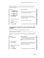
Mask .............................................................................................................................. 6-25
Selecting a mask........................................................................................................ 6-25
Selecting a range of masks.........................................................................................6-25
Assigning a mask to a controller ................................................................................ 6-26
Selecting channels from assignments .........................................................................6-26
Chapter 7 Loops & Links ..................................................................................................... 7-1
Loops ............................................................................................................................... 7-2
Programming an automatic continuous Loop................................................................ 7-3
Programming a manual continuous Loop ..................................................................... 7-3
Programming a manual Loop....................................................................................... 7-4
Programming a finite Loop .......................................................................................... 7-4
Programming an autofollow Loop................................................................................ 7-5
Programming a follow-on cue...................................................................................... 7-5
Erasing Loop assignments ........................................................................................... 7-5
Erasing an autofollow Loop assignment ....................................................................... 7-6
Link.................................................................................................................................. 7-7
Programming a Link between two memories................................................................ 7-7
Programming a Link among a group of memories ........................................................ 7-7
Erasing a Link assignment ........................................................................................... 7-8
Viewing Links............................................................................................................. 7-8
Chapter 8 Modifying Memories............................................................................................ 8-1
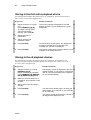
Basic Memory Modification.............................................................................................. 8-2
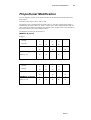
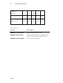
Proportional Modification ................................................................................................. 8-3
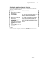
Using STORE STORE...................................................................................................... 8-5
STORE STORE modes................................................................................................ 8-5
Storing to the first active playback device .................................................................... 8-6
Storing to the all playback devices ............................................................................... 8-6
Storing to selected playback devices ............................................................................ 8-7
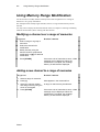
Using Memory Range Modification .................................................................................. 8-8
Modifying a channel over a range of memories ............................................................ 8-8
Adding a new channel to a range of memories.............................................................. 8-8
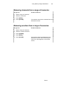
Releasing channels from a range of memories.............................................................. 8-9
Releasing scrollers from a range of memories .............................................................. 8-9
Releasing Channels & Scrollers ...................................................................................... 8-10
Releasing channels .................................................................................................... 8-10
Releasing scrollers.....................................................................................................8-10
iv
Part 3 - File Mangement and Printing
Chapter 9 Data Storage, Retrieval, & Printing ...................................................................... 9-1
Recording Show Files....................................................................................................... 9-2
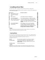
Loading show files............................................................................................................ 9-3
Load options ............................................................................................................... 9-3
Warning Difference..................................................................................................... 9-4
Deleting Show Files.......................................................................................................... 9-5
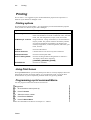
Printing ............................................................................................................................ 9-6
Printing options........................................................................................................... 9-6
Using Print Screen ...................................................................................................... 9-6
Programming a print command Macro......................................................................... 9-6
Part 4 - Playback
Chapter 10 The Crossfader................................................................................................. 10-1
Overview........................................................................................................................ 10-2
Displays.................................................................................................................... 10-2
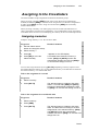
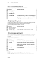
Assigning to the Crossfaders........................................................................................... 10-3
Assigning memories.................................................................................................. 10-3
Assigning editor groups............................................................................................. 10-4
Freeing assignments ....................................................................................................... 10-4
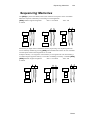
Sequencing Memories..................................................................................................... 10-5
The Playback Keys ......................................................................................................... 10-6
Automatic Go............................................................................................................ 10-6
Exiting a continuous automatic or manual Loop......................................................... 10-7
Modifying the Fade Rate................................................................................................. 10-7
Moving the crossfaders manually............................................................................... 10-7
Using the Wheel........................................................................................................ 10-7
Chapter 11 Controllers & Chasers ...................................................................................... 11-1
Overview........................................................................................................................ 11-2
Displays.................................................................................................................... 11-2
Assign mode ............................................................................................................. 11-4
Controller LEDs........................................................................................................ 11-4
Assigning Memories....................................................................................................... 11-4
Assigning a range of memories to sequential controllers ............................................ 11-5
Assigning an unspecified range of memories to sequential controllers ....................... 11-5
Assigning Masks....................................................................................................... 11-5
Assigning Editor Groups................................................................................................. 11-6
Assigning channels ................................................................................................... 11-6
Assigning Scrollers......................................................................................................... 11-8
Adding text to a grp assignment................................................................................. 11-8
Examining a Controller Assignment................................................................................ 11-9
Freeing Controller Assignments...................................................................................... 11-9
Freeing multiple controller assignments................................................................... 11-10
Freeing all controller assignments............................................................................ 11-10
Using ‘Go Controller’................................................................................................... 11-11
Fade times with ‘Go Controller’ .............................................................................. 11-11
Chasers ........................................................................................................................ 11-12
Chaser displays ....................................................................................................... 11-12
Assigning chasers to controllers............................................................................. 11-14
Playing back chasers ............................................................................................... 11-15
Modifying the chaser rate ........................................................................................ 11-16
v
Assigning Controllers as Submasters............................................................................. 11-18
Assigning controllers as inhibit submasters .............................................................. 11-18
Submastering playback devices................................................................................ 11-18
Sound-to-Light ............................................................................................................. 11-20
Turning on sound-to-light ........................................................................................ 11-20
Turning off Sound-to-Light .................................................................................... 11-21
Sound-to-Light display ............................................................................................ 11-21
Controller response.................................................................................................. 11-21
Part 5 - Advanced Topics
Chapter 12 Events.............................................................................................................. 12-1
Overview........................................................................................................................ 12-2
The Event Menu ............................................................................................................. 12-2
Programming an Event .............................................................................................. 12-3
Adding operations to an Event ................................................................................... 12-3
Deleting an Event ...................................................................................................... 12-4
Adding text to an Event ............................................................................................. 12-4
Examining Events ..................................................................................................... 12-5
Operating Events ............................................................................................................ 12-5
Assigning an Event to a memory................................................................................ 12-5
Erasing an Event from a memory............................................................................... 12-6
Operating an Event using the editor ........................................................................... 12-6
Chapter 13 Effect ............................................................................................................... 13-1
Overview........................................................................................................................ 13-2
Programming an Effect ................................................................................................... 13-2
Using the editor output .............................................................................................. 13-2
Using the editor and playback devices........................................................................13-3
Assigning a pattern.................................................................................................... 13-3
Modifying Effects ........................................................................................................... 13-4
Modifying steps......................................................................................................... 13-4
Removing channels from a step ................................................................................. 13-4
Modifying step time .................................................................................................. 13-5
Inserting a step .......................................................................................................... 13-6
Deleting a step........................................................................................................... 13-6
Assigning Loops to Effects.............................................................................................. 13-7
Re-assigning an automatic continuous loop to Effects ................................................ 13-7
Adding text..................................................................................................................... 13-7
Deleting an Effect ........................................................................................................... 13-8
Copying an Effect ........................................................................................................... 13-8
Playing Back Effects....................................................................................................... 13-9
Examining Effects........................................................................................................... 13-9
Viewing the Effect list ............................................................................................... 13-9
Examining an Effect .................................................................................................. 13-9
Chapter 14 Snaps ............................................................................................................... 14-1
Overview........................................................................................................................ 14-2
Programming a Snap....................................................................................................... 14-2
Adding Text to Snaps...................................................................................................... 14-3
Examining Snaps ............................................................................................................ 14-3
Viewing the snap list ................................................................................................. 14-3
Examining a selected Snap ........................................................................................ 14-3
Erasing Snaps ................................................................................................................. 14-4
Operating Snaps.............................................................................................................. 14-6
Operating Snaps in non-forcing mode ........................................................................ 14-6
Operating Snaps in forcing mode ............................................................................... 14-7
Using Snap to clear all assignments ........................................................................... 14-7
vi
Chapter 15 Macros............................................................................................................. 15-1
Overview........................................................................................................................ 15-2
The Macro Menu............................................................................................................ 15-2
Programming Macros ................................................................................................ 15-3
Modifying Macros..................................................................................................... 15-4
Linking Macros......................................................................................................... 15-4
Dedicated function Macros........................................................................................ 15-5
Adding text to Macros............................................................................................... 15-6
Deleting Macros........................................................................................................ 15-7
Last 40 keypresses..................................................................................................... 15-7
Using Teach Macro ........................................................................................................ 15-8
Programming with Teach Macro................................................................................ 15-9
Operating Macros ........................................................................................................... 15-9
Operating Macros Using Soft Keys............................................................................ 15-9
Operating Macros using the numeric keypad............................................................ 15-10
Part 6 - System Configuration and
Patching
Chapter 16 System Configuration....................................................................................... 16-1
Accessing Service Tools ................................................................................................. 16-2
Configuring in Service Tools .......................................................................................... 16-2
Passcode ................................................................................................................... 16-3
Navigating in the Config System ............................................................................... 16-3
System Type ............................................................................................................. 16-3
CRT number ............................................................................................................. 16-3
Configuring control capacity ..................................................................................... 16-4
Special functions....................................................................................................... 16-4
Special Numbers ....................................................................................................... 16-6
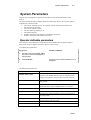
System Parameters.......................................................................................................... 16-7
Operator definable parameters ................................................................................... 16-7
Print menu screen...................................................................................................... 16-8
Chapter 17 Channel and Scroller Patching.......................................................................... 17-1
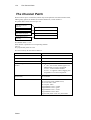
The Channel Patch.......................................................................................................... 17-2
Patching dimmers to channels ................................................................................... 17-3
Patching dimmers to scrollers.................................................................................... 17-3
Patching channels to dimmers................................................................................... 17-4
Clearing patch assignments ....................................................................................... 17-5
Restoring the default patch ........................................................................................ 17-6
Proportional patching ................................................................................................ 17-6
Exchanging dimmers................................................................................................. 17-7
Assigning dimmer curves .......................................................................................... 17-7
Disabling General Master control .............................................................................. 17-9
Enabling General master control.............................................................................. 17-10
Examining soft patch assignments ........................................................................... 17-10
Viewing free dimmers............................................................................................. 17-11
The Scroller Patch ........................................................................................................ 17-12
Selecting a scroller .................................................................................................. 17-13
Patching scrollers to control channels ...................................................................... 17-13
Patching DMX addresses to scrollers....................................................................... 17-14
Defining a dark gel frame........................................................................................ 17-14
Changing the number of frames............................................................................... 17-15
Setting up frames .................................................................................................... 17-15
Copying the scroller setup ....................................................................................... 17-16
vii
Part 7 - Communication Interfaces
Chapter 18 MIDI In/Out..................................................................................................... 18-1
Configuring the System for MIDI.................................................................................... 18-2
Configuring for MIDI in Service Tools ...................................................................... 18-2
Defining the MIDI channel in System Parameters ...................................................... 18-2
Enabling/Disabling MIDI................................................................................................ 18-3
Turning MIDI on....................................................................................................... 18-3
Turning MIDI off ...................................................................................................... 18-3
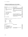
The MIDI Menu ............................................................................................................. 18-3
Enabling and disabling keys and controllers............................................................... 18-4
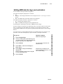
Editing MIDI data for keys and controllers................................................................. 18-5
MIDI Macro ................................................................................................................... 18-6
MIDI Sync...................................................................................................................... 18-6
Setting up MIDI Sync in the master console............................................................... 18-7
Setting up MIDI sync in the slave console.................................................................. 18-7
Enabling/disabling MIDI Sync................................................................................... 18-7
Standard MIDI Codes ..................................................................................................... 18-8
Chapter 19 SMPTE ............................................................................................................ 19-1
Configuring the system for SMPTE................................................................................. 19-2
Configuring the SMPTE/DMX Input connector. ........................................................ 19-2
Configuring the number of frames ............................................................................. 19-3
Teaching SMPTE Time................................................................................................... 19-3
Starting at a selected Event ........................................................................................ 19-4
Exiting the teach function ..........................................................................................19-4
Manual assignment and editing the SMPTE code............................................................. 19-5
Erasing a SMPTE time code ...................................................................................... 19-5
Playback with SMPTE .................................................................................................... 19-6
Exiting SMPTE playback........................................................................................... 19-6
Chapter 20 DMX Input ...................................................................................................... 20-1
Configuring Photon for DMX Input ................................................................................ 20-2
The DMX Input patch ..................................................................................................... 20-3
Patching input channels ............................................................................................. 20-3
Clearing Input patch assignments............................................................................... 20-4
Returning to the default patch .................................................................................... 20-4
Examining DMX input assignments........................................................................... 20-5
Assigning Macros to DMX input ............................................................................... 20-5
Canceling a Macro assignment .................................................................................. 20-6
DMX Input and patch 999............................................................................................... 20-6
Ignoring Patch 999 .................................................................................................... 20-6
Using DMX Input under Patch 999............................................................................ 20-6
Part 10 - Appendices
Appendix A Service Tools................................................................................................... A-1
Accessing Service Tools .................................................................................................. A-2
Main Menu...................................................................................................................... A-2
Diagnostics...................................................................................................................... A-3
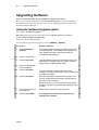
Upgrading Software ......................................................................................................... A-4
Using the Software Upgrade option ............................................................................ A-4
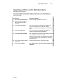
Upgrading software under Disk Operations................................................................. A-5
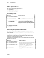
Disk Operations ............................................................................................................... A-6
Formatting disks......................................................................................................... A-6
Recording the system configuration ............................................................................ A-6
Loading the system configuration ............................................................................... A-7
viii
Appendix B Patch 999 .........................................................................................................B-1
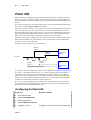
Patch 999 .........................................................................................................................B-2
Configuring for Patch 999 ...........................................................................................B-2
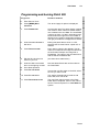
Programming and burning Patch 999 ...........................................................................B-3
Editing the file on a PC ...............................................................................................B-4
Color key for Patch 999...............................................................................................B-5
Examining Patch 999 ..................................................................................................B-5
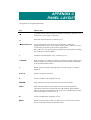
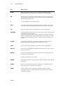
Appendix C Panel Layout ....................................................................................................C-1
Appendix D Photon as Backup for 3B Systems.................................................................... D-1
Overview......................................................................................................................... D-2
Output ............................................................................................................................. D-2
CHAPTER 1
INTRODUCTION
This User’s Guide contains 20 chapters and 3 appendices. The User’s Guide is divided
into 8 parts.
Part 1 - General
•
•
Chapter 1 Introduction
Chapter 2 General Operation
A concise overview of operational features, such as the Editor, Playback Devices, Soft
Keys, Display Formats, and On Line Help.
•
Chapter 3 Displays
Descriptions of the different displays available in Photon and operating instructions
for Display control.
•
Chapter 4 Quick Start
This chapter provides operating instructions for the most basic functions on Photon.
Its purpose is to provide quick instruction to operators familiar with lighting consoles.
Part 2 – Basic Programming
•
Chapter 5 Selecting and Editing Channels and Scrollers
Operating instructions for basic channel and scroller selection, advanced selection
sequences, and assigning dimmer and frame values.
•
Chapter 6 Programming Memories
Basic programming functions, including using the Call function, how to convert
memories to editor groups, assigning Fade Times, programming in Blind mode, and
inserting memories.
•
Chapter 7 Loops & Links
Programming memories with Loops to run as Chasers on the controllers or on the
crossfader. Linking non-sequential memories.
•
Chapter 8 Memory Modification
Operating instructions for basic memory modification, quick modification for
memories assigned to playback devices using the STORE STORE function, and Delta
tracking modification.
Part 3 – File Management and Printing
•
Chapter 9 Data Storage, Retrieval, & Printing
How to Record and Load show files, and Printing options.
Part 4 - Playback
•
Chapter 10 The A/B Crossfader
Making assignments to the A/B crossfader, playback using automatic Go commands
or manual operation, and automatic Rate control.
•
Chapter 11 Controllers
Assigning memories, groups, and Chasers to the Controllers. Using the automatic Go
and manual playback operations. Rate control for Chasers.
Part 5 – Advanced Topics
•
Channel 12 Event
Program events to operate multiple assignment and playback commands. Events can
1-2
Using this User’s Guide
be operated when assigned to memories sequencing on the A/B crossfader, in the
editor, or using SMPTE.
•
Chapter 13 Effect
Program Effects in the Effect menu. Steps comprise an Effect. Effects can be assigned
various chaser pattrers.
•
Chapter 14 Snap
Store ‘snapshots’ of all playback device assignments and their fade status. Snaps are
analogous to preset pages for Controllers. Photon supports 99 Snaps.
•
Chapter 15 Macros
Photon supports up to 999 Macros. Operating instructions for programming Macros
blind, in the Macro menu, or live using the Teach macro function.
Part 6 – System Configuration and Patching
•
Chapter 16 System Configuration
General system Configuration in Service Tools and using operator definable system
parameters in the System Parameters menu.
•
Chapter 17 Channel and Scroller Patching
The Channel Patch provides functions for soft patching dimmers and channels,
assigning dimmer curves, assigning proportional levels to dimmers, examining patch
assignments. The Scroller Patch provides easy functions for setting up frames,
assigning control channels to scrollers, and copying scroller set ups.
Part 7- Communication Protocols
•
Chapter 18 MIDI
Enable MIDI communication and edit MIDI codes in the MIDI menu. The MIDI
synch option allows a second lighting console to synchronize crossfade operations
with the main console.
•
Chapter 19 SMPTE
Assign SMPTE time codes to Events using the live Teach function and enable Photon
for automatic operation using SMPTE transmission.
•
Chapter 20 DMX Input
Patch DMX Input channels to operate local console channels or macros.
Appendices
•
Appendix A Service Tools
Operating instructions for disk formatting, the Hardware diagnostics tool, and
software upgrade functions in Service Tools.
•
Appendix B Patch 999
Instructions for editing Patch 999, which allows logical channel patching.
•
Appendix C Panel Layout
Short descriptions of all panel keys. The keys are arranged alphabetically.
Photon
Using this User’s Guide
1-3
Using this User’s Guide
Setting up Photon
If you are setting up the system for the first time, you may want to consult Chapter 16
System Configuration and Chapter 17 Channel Patching
New users
If you are new to lighting consoles or are unfamiliar with Compulite consoles, familiarize
yourself with the information in chapters 2 – 11. These chapters provide you with general
information and give you the building blocks to create and modify memories (cues), and
play them back. Chapters 12 – 20 deal with more advanced functions.
Common Terms
Three major capabilities are basic to lighting consoles: editing, playback, and patching.
Editing is the ability to select channel and scrollers, assign intensity and parameter values,
and record the resulting stage picture as a memory or cue. All functions related to the
playback structure of the show, such as event assignments, snaps, loops, and links are part
of the editing functions.
Playback is the ability to replay all the show data that you have created while editing.
Playback can be manual and automatic.
Patching includes all of the patching functions, which instruct the system how to
communicate with conventional projectors, color scrollers, other DMX512 protocol
elements, and moving lights that are controlled by the lighting console.
Editing terms
• Channel - The control channel for DMX512 devices, which are not moving devices.
These include conventional projectors, color scrollers, smoke machines, etc.
• Intensity - Dimmer intensity of channels.
• Present or active (in the editor) - Channels that are displayed in white. Everything
present/active in the editor is included when recording a memory.
• Selected (in the editor) - Channels that are displayed in red and therefore can be
assigned intensity or scroller values.
• Memory - is analogous to cue. The group in the editor, comprising the lighting state
on-stage, is stored as a memory. Memories are then played back.
• Value - The numerical value assigned to a parameter or a dimmer.
• Store - Save the information in the editor.
• Erase - Delete selected data.
• Modify - Change stored information and fade rates.
• Frame - Scroller frame.
Photon
1-4
Text conventions
Playback terms
• Go - Initiate an automatic crossfade, controller fade, or chaser run.
• Hold - Stop any fade or chaser in progress.
• Multifade - Initiate a fade to the next memory in sequence before the fade in progress
is complete.
• End Stop - When crossfaders or the controllers are at either 0% or 100%.
• Off the End Stop- When the crossfaders or the controllers are at more than 0% or less
than 100%.
• Rate - The rate at which channels fade in or out during a crossfade. The rate at which a
chaser runs.
• Step - Manually moving from the current memory to the next memory of a chaser.
• Sequence - The numerical sequencing of the memories on the A/B or C/D crossfaders.
Text conventions
•
Panel [KEYS] are in square brackets, all caps, and bold.
•
Messages are in italics.
•
# refers to a number entered on the numeric keypad.
•
Command line refers to the sequence of keystrokes executed and displayed in the gray
line at the bottom of the display monitor. The keystrokes in the command line are
represented in italics.
•
Prompt line refers to prompts occurring in menus; these are italicized.
•
Desk, console, and system are used interchangeably.
Output Level Conventions
Photon uses the HTP (Highest Takes Precedence) convention for dimmer channels.
Scroller frames are subject to a rigid control hierarchy.
The Editor always overrides any other control devices.
Photon
CHAPTER 2
GENERAL OPERATION
This chapter includes:
The Editor Section
F keys
Programming memories
Editor color key
Editor error trapping
Clearing the editor
Parameter Control
The wheels
A/B Crossfader
Controllers
Soft Keys
Assigning the default mode
Assigning a temporary mode
Using the Soft Keys for playback control
Color code for Soft Key LEDs
General Master
Menus
Accessing menus
Exiting the menu mode
Text & the Alphanumeric Keyboard
A page of text
Erasing text
Using the text keyboard for programming
Locking/unlocking the keyboard
On-line Help
System Status
2-2
The Editor Section
The Editor Section
Editing keys are used to:
•
Select channels
•
Assign intensity
•
Program memories
•
Manipulate the display.
•
Assign memory attributes such as Loops and Links.
Most keys are single purpose keys. Some keys however access two different functions. The
function in the lower half of the key is accessed using the [SHIFT] key.
The numeric keypad is used for number selections. Some selections may be done on the
Soft Keys.
Keystrokes appear in the yellow command line at the bottom of the display.
Selected channels appear in red. Channels displayed in red are may be assigned values.
Channels displayed in white are present in the editor, but not currently selected. They are
included in any memory that is recorded.
The Editor operates in Live and the Blind modes. In Live mode any alterations made to the
stage picture are visible on stage. In Blind mode, memories are programmed or modified
without any interruption of the active stage picture.
F keys
The Function (F) keys are multi-purpose soft keys, generally used while working in menus.
When the system is not in menu mode, F1-F5 offer immediate access to Macros 1-5. F6
accesses the rest of the macros. In menu mode these keys access the convenient menu
functions and options. These keys are also used for Delta application and editing SMPTE
time codes.
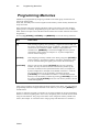
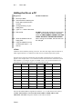
Programming memories
Memories are programmed by selecting channels and assigning intensity or scrollers frame
values and then storing the resulting stage picture as a memory.
Each memory may be programmed for the following information:
•
Fade in and out time, from 'cut' to 999.9 seconds.
•
Delay, wait -in, and wait out time, from 'cut' to 999.9 seconds.
•
An automatic follow-on memory created by using the loop function.
•
Loops containing any number of memories.
•
Links between non-sequential memories.
•
Event assignments that automatically operate multiple functions
•
Text
Photon
A/B Crossfader
2-3
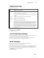
Editor color key
Color
Status
Red field
Channels selected in the editor. Channels displayed in red can be
assigned intensity levels and, if controlling scrollers, frame values.
White field
Channels that are present in the editor. When storing an editor group as
a memory the channels displayed in white and red are included in the
memory.
Dark blue
Channels selected under memory modification (see Chapter 8
Modifying Memories).
Editor error trapping
Photon has efficient error trapping, meaning that you cannot go too far wrong. An illegal
key press is immediately recognized. If you make a mistake the system displays messages
such as Illegal Number or Invalid Sequence.
To get rid of this message and continue working, press the correct key. The correct
keystroke clears the error and allows the operation to continue.
Clearing the editor
You can clear the editor by pressing either [RESET] or [CLEAR].
Using RESET
Press [RESET] once to fade out the channels in the editor in Default Fade Time. The
Default Fade Time can be modified in the System Parameters menu. (See Chapter 16 System Configuration).
Press [RESET] twice to bump out the channels in the editor.
Using CLEAR
[CLEAR] works as a regressive clear function.
Press [CLEAR] once- the command line clears, leaving only the selection mode (channel
or memory).
Press [CLEAR] [CLEAR] - the output of selected channels (displayed in red) are cleared.
Press [CLEAR] [CLEAR] [CLEAR] - the selection mode is cleared from the command
line. The editor is now idle.
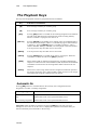
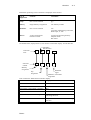
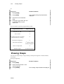
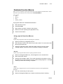
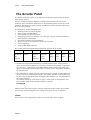
A/B Crossfader
The A/B crossfader is the playback crossfader of the system.
Memories assigned to A/B crossfade, sequencing in numerical order, when either an
automatic Go command is received or the crossfade is performed manually.
Photon
2-4
A/B Crossfader
Fades are executed automatically by pressing [GO] , fading according to prerecorded fade
rates, or by manual movement of the crossfader. The crossfade rate can be overridden at
any point in the fade progression by using the rate wheel.
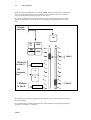
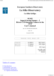
The A/B crossfader area of the console consists of: the A fader and the B fader, an LED
display for each fader that shows their current assignments, assignment keys and control
keys.
Crossfade
control keys
GO
GO
TO
HOLD
10
SEQ
AUTO
BACK
LEDdisplay
for fader A
A/B
Assignment
keys
A
B
LEDdisplay
for fader B
A
B
0
9
1
8
2
7
3
6
4
5
5
4
6
3
7
2
8
1
9
0
10
fader A
fader B
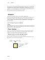
Figure 1 The A/B crossfader area
The Playback area of the Stage display (display formats 1 and 3) shows the current status of
the A/B crossfader.
The X-Fade Exam is a display dedicated to the A/B crossfader and is generally used during
playback. (see Chapter 3 – Displays)
Photon
Controllers
2-5
The A/B crossfader supports memory Loops, Links, and Event assignments.
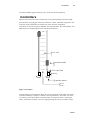
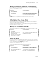
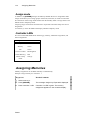
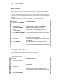
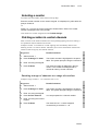
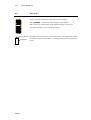
Controllers
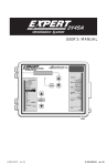
Photon has 20 controllers. Each controller has an associated Soft Key and colored LED.
The controllers accept groups of channels, memories, Chaser, and Effect assignments. The
controller position determines the output level of the controller assignments.
Controllers can also be assigned to submaster the controller banks, the A/B crossfader, and
DMX Input or as inhibit submasters for channels and memories.
10
9
8
7
6
5
level scale
4
3
2
Controller handle
1
0
color coded LED
Soft Key
1
2
controller number
level
scale
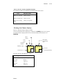
Figure 2 Controllers
Colored LEDs provide information about the type of assignment and the fade status of the
Controllers/Soft Keys. Example: Controller 1 is assigned a chaser. The chaser is on hold
(not running). The LED under the controller blinks red. When the chaser is running the
LED is red and does not blink. If you are stepping through the chaser, the LED is orange.
Photon
2-6
Soft Keys
Soft Keys
The Soft Keys have 3 modes.
Mode
What the Mode does
Assign mode
Allows the assignment of groups of channels, memories, or chasers to
controllers.
A fade function fades the controller assignment up and down.
The Soft Keys are also used for Go commands and to flash the assignment.
10 simultaneous chaser assignments can be made. Chasers are assigned in
hard run mode or soft run mode and are easily switched from one mode to
the other. There is a special dedicated chaser display.
Controllers can be assigned as inhibitive submasters or can submaster the
upper bank of controllers, lower bank of controllers, A/B, and DMX Input
channels.
Macro mode
Direct access to 40 Macros.
Snap mode
Direct access to 20 Snaps with 2 snap functions modes - non-forcing
(additive) and forcing (override)
Assigning the default mode
The Soft Key default mode is assigned by a double hit on [ASSIGN], [SNAP], or
[MACRO].
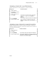
Assigning a temporary mode
You can temporarily change the Soft Key mode with a single hit on any of the mode keys.
The temporary mode is valid until the one of the Soft Keys is pressed; then the Soft Keys
return to the default mode. Temporary modes are preceded by an asterisk (*) the LED
display.
Example: The default mode is Assign. You want to go, temporarily, to Macro mode in
order to operate Macro 11. Press [MACRO] then SK11. The Soft Key mode returns to
Assign mode.
Each mode has a secondary function that is accessed by pressing [SHIFT].
Mode
SHIFT function
Assign
Fade memory or group assignment from the controller level to FL or to 0.
Manual stepping for chaser assignment.
Macro
Accesses macros 21 - 40.
Snap
Operates Snap in forcing (override) mode.
Photon
Soft Keys
2-7
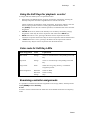
Using the Soft Keys for playback control
In Assign mode the Soft Keys have 4 operational modes:
1.
Flash mode is the default function for group and memory assignments. Pressing the
Soft Key bumps the controller assignment from its current level to full.
Chaser Go/Hold is the default for chaser assignments. Pressing the Soft Key starts the
chaser. Pressing it while a chaser is running stops and blacks out the chaser.
The [SHIFT] accesses the Go Controller operation, an automatic fade of the controller
assignment.
2.
LATCH When active (LED on) the Soft Keys are on/off keys for memory and grp
assignments. Latch may be used in conjunction with either of the SOLO keys.
3.
SOLO When this is active, pressing a SK blacks out the output from all of the
controllers except the selected one. May be used in conjunction with the latch function.
4.
– SOLO When this is active, pressing a SK blacks out the output of the selected
controller only. May be used in conjunction with the latch function.
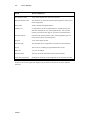
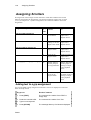
Color code for Soft Key LEDs
Mode/Assignment
Color
Explanation
Macro mode
Orange
There is a recorded macro corresponding to the Soft
Key.
Snap mode
Orange
There is a recorded snap corresponding to the Soft
Key.
Assign mode
Green
When there is a group, memory, or submaster
assignment present.
Chaser assignment
Red blink
Red solid
Orange
Chaser on Hold
Chaser running
Step
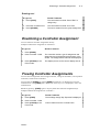
Examining controller assignments
It is possible to examine all controller assignments in the Assign, Macro, and Snap modes:
Press [EXAM] and the Soft Key.
¾Note
In order to use the exam function the mode must be the default mode and not a temporary
mode.
Photon
2-8
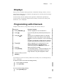
General Master
General Master
The General Master controls the overall dimmer output of the console.
The General Master fader has a blackout key, which turns off all dimmer outputs in the
system. The GM blackout key can be disabled in the System Parameters menu.
The level of the General Master is displayed in the upper right corner of the display. The
maximum level of the GM can be set to 100 or 200, in Service Tools/Config sys/F3.
Channels can be removed from General Master control. This is useful when using scrollers
and DMX devices such as smoke machines. (See Chapter 17 Channel and Scroller
Management)
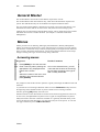
Menus
Menus provide tools for Patching, defining System Parameters, Memory Management,
Macros, and other special functions. The F (Function) keys are used to access the options
and functions in each menu. Easy to follow prompts guide you through all menu functions.
Once you have opened the selected menu, you will notice that the functions of the F keys
change according to the type of task currently being addressed.
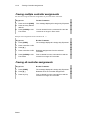
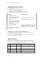
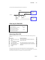
Accessing menus
Keypresses
Results/Comments
1. Press [MENU] to view the menu list.
2. Enter a menu by either pressing the
appropriate F key, displayed at the
bottom of the screen.
Or
Select the number of the menu, as it
appears in the numbered list and
press [ENTER]
Once in the selected menu, you will
notice that the functions of the soft (F)
keys change according to the type of
task currently addressed.
The prompt line asks all the relevant questions to guide you through the different tasks and
functions. .
If you make an error entering information while in a menu F6 Restart usually returns to
the beginning of the command chain. If you have made an error entering a number
selection, pressing [CE] usually clears the error.
Number selections in the menu mode are entered on the numeric keypad of the console or,
in some cases, the alphanumeric keyboard. Text is typed on an alphanumeric keyboard.
Many menus have more than 5 functions available. It is generally assumed that if you do
not see the function under discussion, you will page until you see the option. To view the
next page of functions press: F6 More Function
Photon
Menus
2-9
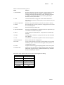
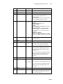
Photon contains the following menus:
Menu
Purpose
1. Channel Patch
Dimmer management includes soft patch, assigning dimmer curves,
defining proportional patch per dimmer, exchanging dimmers,
enabling or disabling General Master control. and testing channels
or dimmers. Patching for DMX input. Examining patching for
dimmers, channels, and scrollers.
2. Load
Load show files from a floppy disk. All the data contained in a
show file can be loaded or selected parts, such as Libraries only and
Macros only.
3. Memory Operations
Rename, copy, delete memories, and clear the console’s memory.
5. Record
Recording Photon’s memory contents to a floppy disk or to the hard
disk. File management.
7. Printer
Generate hard copy of show data.
8. System Parameters
General system information is displayed. There are options that you
can redefine to customize the system.
9. Macro
Create, modify, and delete Macros. Assign Macros to DMX input
channels.
10. Effect
Program Effects. Effects are a group of chaser steps with selectable
chase patterns.
11. Test
Test channels. Test dimmers regardless of their channel soft patch.
14. Delete Play/Act
Delete shows files from a floppy disk.
20. Scroller
Assign control channels to scrollers, fine tune frame set ups, enable
the dark gel option. This menu does not appear if the system is not
configured for scrollers.
21. Event
Program Events that trigger multiple playback events in the system.
23. MIDI In/Out
Enable keys and controllers for MIDI communication. Edit default
MIDI codes. Program macros of MIDI command strings. Enable or
disable the MIDI Synch function.
Some of the F key functions may be carried out on the keypad as in editing:
F Key in menu
Thru
KEYPAD
[ ]
Channel
[CHANNEL]
Store
[STORE]
Memory
[MEMORY]
Next
[+]
Previous
[-]
Æ
Photon
2-10
Text & the Alphanumeric Keyboard
Exiting the menu mode
Pressing [RESET] exits the menu mode and resets the menu you have just exited. Press
once to return to menu list. The second press returns you to stage display.
[MENU] also exits the menu mode. Pressing this key exits the menu you are working on
without, in most cases, resetting the menu editor.
If for example, you are busy in the Macro menu and you must temporarily exit the menu,
exit by pressing [MENU] returning to stage display. When you want to return to the Macro
menu, press [MENU] to return to the point from which you exited the Macro menu and
continue working.
You can exit the following menus without resetting the menu editor:
• Channel Patch
• Macro
• Scroller Patch
Text & the Alphanumeric Keyboard
Text is typed on the alphanumeric keyboard.
You can add text to Macros, memories, to show files when recording to the diskette, to
Snaps, Events, controller group assignments, and even leave a note for the second shift
crew.
Operating instructions for adding text to the above mentioned items are included in the
sections dealing with those subjects.
A page of text
One page is available for text typed on the alphanumeric keyboard. This is useful for
recording any notes about special rigging, color changes during interval, cue synopsis, any
special comments pertaining to the show, etc.
If the blue text page contains text it is the first display to come up when the system is
turned on. This makes a convenient place to leave notes and messages for the next shift
crew.
To create a page of text:
Keypresses
Results/Comments
1. Press [TEXT] [TEXT]
A blank blue screen is displayed. This is the text page.
2. Type the text on the
alphanumeric keyboard
3. Press [STORE]
¾Note
If there is text on the Text p age, you can access the page by pressing Insert on the
alphanumeric keyboard.
Photon
Text & the Alphanumeric Keyboard
2-11
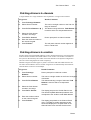
Erasing text
The [ERASE] key is used to erase text.
Example: Delete the text from the Text page.
Keypresses
Results/Comments
1. Press [TEXT]
2. Press [TEXT]
The blue Text page is displayed/
3. Press [ERASE]
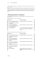
Using the text keyboard for programming
The text keyboard can be used to program memories. .
The keyboard equivalents are:
a – Text
o – On*
S – Status*
b – block*
p – Part*
T – SMPTE
c – Channel
q – Memory
@ - intensity
d - Page Down
r - Rem Dim*
^ - Except*
e – Effect
s – Store
[ - +@*
f – Full
t – Time
] - @*
g – Mask
u - page up 2
Bs – CE
h – Help
v - (not used)
spacebar – clear
i - Teach Macro
w – Wait
% - flash
j - Move Fade*
x – Exam
& - +1 store
k – Link
y - (not used)
>- →
l - Loop
z – Zero
Tab – Stage
m – Menu
E – Event
Del – Erase
n – Snap
F – Frame
Esc - reset during editing,
after inserting text to
memories, etc. use ESC to
exit text mode.
* These keys are not used with Photon.
Locking and unlocking the keyboard
The alphanumeric keyboard has a lock to prevent unintentional editing. Activate the lock
by pressing Alt A. Unlock the keyboard for editing functions by pressing Alt A again. This
lock does not affect the functioning of the alphanumeric keyboard when [TEXT] is selected
on the console.
¾Note
To use the Print Screen function on the text keyboard, you must first “unlock” the
keyboard.
Photon
2-12
Getting Help
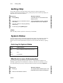
Getting Help
On-line help contains a short description of each of the keys and the important key
sequences. When the help window is open, pressing a key on the console only displays its
help and does not execute its function.
Keypresses
Results/Comments
1. Press [HELP]
A window opens in the middle of the
display screen.
2. Press any key you would like to know
more about.
A short explanation and any relevant
keystroke sequences are displayed.
3. You can continue in Help by pressing
another key.
4. To exit help, press [HELP] again.
¾Note
When the Help window is open the console keys are disabled!
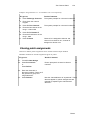
System Status
You can check the status of connected peripherals from panel. The peripherals include the
Submaster Wing, the Macro Extension Keyboard, the Remote Control, the Wire/less
Remote Control, and the alphanumeric keyboard. You are notified if the battery is getting
low.
Color key for System Status
Color
What it means
Blue
Device installed and functioning correctly.
Red
Fault
White
Not installed
What to do in case of disconnection
If a peripheral is physically disconnected or there is a communication problem a red
blinking S, appearing in the command line, notifies you that there is a problem. You can
turn off the blinking S by going to the System Status window and selecting F2 Ignore.
Keypresses
Results/Comments
1. Press [•]
The System Status window opens. The
peripheral devices status is displayed.
2. Press F1 and select the device
Photon
System Status
2-13
3. Press F2 Ignore
4. Press [STAGE] or [CLEAR] to return
to the editor.
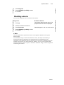
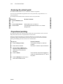
Disabling a device
You can also disable any device connected to the console.
Keypresses
Results/Comments
1. Press [•]
The System Status window opens. The
peripheral devices status is displayed.
2. Press F1 and select the device
3. Press F3 Disable
Disabled appear in red next to the device.
4. Press [STAGE] or [CLEAR] to return
to the editor.
¾Note
When the alphanumeric keyboard is locked it is designated as Disabled in the System
Status window.
If the Submaster Wing is disconnected from the console, the output from the Wing is
moved to the editor and the Status error message blinks in the command line. The
assignments to the Submaster Wing are retained. If you reconnect the Submaster Wing, the
situation is the same as prior to the disconnect. However, if you go to the System Status
window and tell the console to ignore or disable the Submaster Wing, all of the assignments
on the Wing are released.
Photon
CHAPTER 3
DISPLAYS
This chapter includes:
Overview
Display Control
Display Formats
Selecting display options
Customizing the display format
The Stage Display
The Playback Display
Messages and Commands
Output Color Key
The X-Fade Exam Display
Exam Displays
3-2
Overview
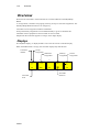
Overview
All the parameters of the system are displayed on a video display monitor. There are 9
display formats to chose from.
The area at the top of the screen is reserved for messages, Blind mode flag, MIDI status,
and the General Master level. The area at the bottom of the screen houses the command
line, a clock, and the last stored memory or the last memory entered into the editor. The
command and message areas are common to all of the display formats.
When viewing the Stage display, which shows the active output, a color code helps you
differentiate between the different output sources.
Display Control
The following keys are used for display control:
Key
What it does
[STAGE]
Access the Display Format options. Return to the Stage Display from most
Exam displays.
[PAGE UP]
Go to the next page.
[PAGE DN]
Go to the previous page. Access this key using [SHIFT].
[MENU]
Toggle the display between the Menu list and Stage mode.
[+]
Go to the next item. Example: Go from memory 2 exam to memory 3 exam.
[-]
Go to the previous item. Example: Go from memory 3 exam to memory 2
exam.
Display Formats
0.
Channel display only. The display includes scroller frames. The color of the channel or
scroller number displayed depends on the origin of the data, whether it derives from
the A/B crossfaders, a controller, the editor, or tracking.
1.
Channel and playback. The playback display includes controller status and A/B status.
2.
X-fade Exam shows the incoming and outgoing memories, a list of the next memories
in sequence, controller/chaser status, chaser assignments, A/B fade rate, and previous
memory on A/B.
3.
X-fade and playback.
In addition to the 4 main display options, the `Status Window' section of display formats
offers further display configurations.
Photon
The Stage Display
3-3
Selecting display formats
The display option framed in red is the current display.
Keypresses
Results/Comments
1. Press [STAGE]
The display format options are shown on the
CRT.
2. Enter the number of the display
you want on the numeric keypad.
The display jumps to the selected format.
or
Keypresses
Results/Comments
1. Press [STAGE]
The display format options are shown on the
monitor.
2. Press F1 until the display format
that you want is framed in red.
3. Press [STAGE]
The display jumps to the selected format.
The Stage Display
The Stage display formats for channels are formats 0 and 1.
The channel number, intensity, and frame number (if the channel number also serves a
scroller) are shown. Channel displays are display formats 0 and 3.
Customizing the display format
There are 4 additional options for customizing the display formats. The options appear in
the Status Window to the right of the display options.
Display
What it shows
Stage Scrlr
A special display area for scroller information. The basic channel display
will no longer show frame information, but scroller channels will still be
marked with an 's'. Under the channel display, the special scroller display
shows the scroller channel number, the dimmer intensity (if any), and the
frame status.
Assign channels
Channels that have assignments (are used in memories) are displayed in
sequential order. This option also influences the display when selecting
channels. Example: Assume that you have not programmed any memories
yet. Select channels 1, 5, 10, 15. If you have chosen the assign channels
option, that is how they will appear on the screen. In the default format the
display would look like this:
1 5 10
15.
Jump display
The display automatically jumps to the page where the selected channel
appears.
SQZ (squeeze)
display
This option is available only if the Stage Scrlr option is active and the
scrollers are displayed separately. This provides more lines for displaying
channels.
Photon
3-4
The Playback Display
Keypresses
Results/Comments
1. Press [STAGE]
2. Press F2 to move the
cursor to your selection.
The cursor points to the options.
3. Press F3
The option is selected, highlighted in the Status
Window. The display format options are updated with
the selected status.
The Playback Display
The Playback Display is available on display formats 1 and 3.
The playback display shows the A/B crossfader status. The information on the crossfader
includes the current and incoming assignments, the fade rate, loop information, and the
Auto status for Event operation. There is a dynamic display of a running crossfade.
When the 20 controllers are in Assign mode the level of the controllers in percentage and
the type of assignment are displayed.
Assignment
Display
Memory
Memory number
Grp
grp
Chaser
First and last memories of the chaser assignment
Soft chaser is marked with an ‘s’
Submaster
sub
When the Soft Key mode is Macro or Snap the controller display area is labeled according
to the mode. The first 5 characters of the text for the Macros and Snaps are displayed.
Messages and Commands
Messages appear at the top of the screen on the Stage display:
•
•
•
•
•
•
•
Messages
The Blind mode flag
MIDI status
MIDI synch status
Grand Master level
SMPTE time code
The Teach Macro flag
The yellow line at the bottom of the screen houses:
• The command line - The command line echoes the keypresses and contains up to 40
characters.
• The clock
• Delta flag
• The last memory recorded (L) or entered (E) into the editor.
Photon
Output Color Key
3-5
Output Color Key
The color key for channels is:
Color
Output source and status
Red
Selected channels, active in the editor, addressable by the wheel or keypad.
White
Channels that are present in the editor, but not selected. Channels appearing in
white are included when storing a memory.
Green
Scroller frame values appear in green when the scroller is selected or active in
the editor.
Dark blue
A memory entered to the editor for memory modification..
Light brown
Output deriving from a controller.
Light blue
Output deriving from the A/B playback.
Gray
Tracking scrollers. DMX Input channels.
Yellow
Match. This only appears in special circumstances. When the editor level of a
channel that has been stored using STORE STORE is different than the level of
the output source. Example: Channel 1 is output from controller 1. The
controller level is 25%. Channel 1 was selected in the editor at Full intensity
then stored. The editor does not release channel 1. So as not to cause a jump in
the light on stage. the editor retains channel 1 at Full intensity displayed in
yellow. Moving the controller 1 to match the editor level releases the channel
from editor control.
To view the color key press [HELP].
Press [HELP] a second time to exit.
The X-Fade Exam Display
The X-Fade Exam appears in display formats 2 and 3. This display shows a short memory
list of the next few memories sequencing on the A/B crossfader.
Bar graph representations of the A/B crossfader dynamically display the progress of a
crossfade. In display format 6 there is an expanded chaser display.
Exam Displays
There are 2 types of Exam displays: strong displays and weak displays.
Weak displays are cleared by any subsequent keypress.
Strong displays remain on the screen and you can continue to work keeping the display on
view. An example of a strong display is the selected channel exam. Example: you can exam
channel 1 and then perform a memory range modification while viewing channel 1 exam.
Press [STAGE] to exit strong exam displays.
Exam displays include:
Photon
3-6
Exam Displays
Exam
What is displayed
Free channels exam
A list of the channels not used in any memory.
Selected channel exam
The memories in which the selected channel appears, intensity and
frame assignments.
Track sheet
Tracks channels through memories...
Memory list
A sequential list of all recorded memories, including loop, link,
fade time information, text, and assigned Events. You view the
memory list from the first page or start from a selected memory.
Selected memory
Channels with intensity/frame values, time assignments, parts (if
used) and text for the selected memory.
Snap list
A list of the Snaps and text.
Selected Snap
The playback device assignments recorded in the selected Snap.
Events
The Event list, including assigned SMPTE time codes.
Effect list
A List of all Effects.
Selected Effect
The steps and time information for the selected Effect.
Controller assignments
Information pertaining to the assignment on the selected controller.
Sequences for accessing the exam displays may be found in the discussion of the different
functions.
Photon
CHAPTER 4
QUICK START
This chapter includes:
Setting Up Photon
Configuring Photon
Patching
Patching dimmers to channels
Patching scrollers to channels
Selecting Channels
Selecting channels & assigning intensity
Selecting scrollers & assigning frames
Programming Memories
Playback Memories on A/B
Playback Chasers
Recording a Show File
4-2
Setting Up Photon
Setting Up Photon
1. Connect the alphanumeric keyboard and the monitor to the appropriate ports
on the back panel.
2. Connect the DMX lead to the output port.
3. Plug the power cable into a power source.
4. Press and hold the [CE] and [CLEAR] keys while switching on the console.
5. Release the [CE] and [CLEAR] keys. Photon goes through its boot up process
and finally displays the main Service Tools menu.
6. The next step is configuring Photon.
Configuring Photon
You must tell Photon how many dimmers and channels, and scrollers you are running.
The instructions below treat this subject at its simplest level. For more information see
Chapter 16 System Configuration.
1. Looking at the main Service Tools menu, press F3 Config System.
2. Enter the number of channels, dimmers, and scrollers that you will be running.
3. Press F6 Enter & exit.
4. Press F6 Store configuration.
5. Switch off Photon.
6. Switch on Photon.
7. When the main Service Tools menu is displayed, press F1 Cold Start.
Photon
Patching
4-3
Patching
All the menus have easy to follow prompts that guide you through the various functions.
Patching should be done before recording any memories.
Photon has 2 Patch menus:
•
Channel Patch (menu 1) - Soft patch dimmers to channels, assign dimmer curves,
assign proportional patch, exchange dimmers, examine patch assignments,
enable/disable General Master control, patch DMX Input.
•
Scroller Patch (menu 20) - Patch scrollers to control channels, determine dark gel
assignments, fine tune gel string placement.
Patching dimmers to channels
1. Go to the Channel Patch menu – [MENU] [1] [ENTER].
2. Press F1 Assign Dimmers.
3. Enter a dimmer number in answer to the prompt.
4. Press F3 To Channel.
5. Enter a channel number in answer to the prompt.
6. Press F1 Store.
See Chapter 17 - Channel and Scroller Patching, for further information.
Patching scrollers to channels
1. Go to the Scroller Patch menu - – [MENU] [20] [ENTER].
2. Select a scroller by entering the scroller number on the numeric keypad or by [+]
and [-] to move the cursor (the colored bar) to the scroller you want.
3. Press F1 Assign To Channel.
4. Enter the channel number in answer to the prompt.
5. Press F1 Store.
See Chapter 17 - Channel and Scroller Patching, for further information.
Photon
4-4
Selecting channels & assigning intensity
Selecting channels & assigning
intensity
1. Press [CHANNEL].
2. Select the channel number on the numeric keypad.
3. Use the dimmer wheel or press [FULL], [ON]. You can also press [@] and assign
an intensity on the numeric keypad.
See Chapter 5 - Selecting & Editing Channels and Scrollers, for more information.
Selecting scrollers & assigning frames
1. Press [CHANNEL].
2. Select the channel number on the numeric keypad.
3. Optional – Assign dimmer intensity.
4. Press [FRAME] and use the wheel to scroll the gel ribbon or assign a frame on the
numeric keypad.
See Chapter 5 - Selecting & Editing Channels and Scrollers, for more information.
Programming Memories
1. Select channels using the numeric keypad.
2. Assign intensity using the dimmer wheel or press [@] and assign an intensity
value using the numeric keypad.
3. Select a scroller channel.
4. Press [FRAME] and use the wheel to scroll the gel ribbon or assign a frame on the
numeric keypad.
5. Press [MEMORY] or press [=]. (See Special Functions in Chapter 16.)
6. Enter the memory number using the numeric keypad.
7. Make fade time assignments by selecting the time in, time out, wait in, wait out, or
delay and entering the time assignment on the numeric keypad.
Press [TIME #] for time in.
Press [TIME] [TIME #] for time out.
Press [WAIT #] for delay.
Press [WAIT] [WAIT #] for wait in.
Press [WAIT] [WAIT] [WAIT #] for wait out.
8. Press [STORE].
9. Press [RESET] to clear the editor or continue editing without resetting the editor.
See Chapter 6 - Programming Memories, for further information.
Photon
Playback Memories on A/B
4-5
Playback Memories on A/B
1. Select a memory by pressing [MEMORY] and the memory number.
2. Press A or B. It is recommended to assign the memory to the inactive fader; if the
fader is at A assign the memory to B, if the fader is at B assign the memory to A.
3. Move the fader so the memory is active on stage.
4. Press [SEQ]. The next memory is now on board.
5. Press [GO] to begin the crossfade from the active memory to the memory on
board.
See Chapter 10 - The Crossfader, for further information.
Playback Chasers
1. Chasers are played back on the controllers.
2. Select a range of memories - [MEMORY] [#
assignment, select the first memory only.
Æ#]. If the first memory has a loop
3. Select the chaser playback mode by pressing [HARD] or [SOFT].
4. Press the Soft Key, for one of the controllers. The SK LED flashes red.
5. Raise the controller handle.
6. Press [GO] to start the chaser.
See Chapter 11 - Controllers, for further information.
Recording a Show File
1. Put a formatted diskette in the floppy drive.
2. Press [MENU] [5] [ENTER] to go to the Record menu.
3. Press F1 Play/Act.
4. Enter a number for the show file using the numeric keypad.
5. Optional – Press F2 Text and type a label on the alphanumeric keyboard.
6. Press F1 Press.
7. Press F1 Yes.
See Chapter 9 - Data Storage and Retrieval.
Photon
CHAPTER 5
SELECTING AND EDITING
CHANNELS & SCROLLERS
This chapter includes:
Selecting channels
Selecting single channels
Selecting non-sequential channels
Selecting a range of channels
Excluding channels from the range selection
Reselecting the last channel selection
Grabbing channels in the editor and on-stage
Assigning intensity levels
Dimmer level assignments using @
Repeating an intensity assignment
Releasing a channel from the editor.
Selecting and Editing Scrollers
Assigning frame values
Releasing a scroller from a memory
5-2
Selecting Channels
Selecting Channels
Single channels, groups of non-sequential channels, and a range of sequential channels
can be selected.
There are special selection sequences that grab channels that are present in the editor
together with channels active on stage.
There are several series of keystrokes to select one or more than one channel at a time.
These keystrokes may be combined in any way lending great versatility to channel
selection.
There are quite a few key combinations that can be used for channel selection. The object
of the different key sequences is to make rapid selection possible.
The Wheel is used for intensity levels and scroller frame selection. Intensity and scroller
frames may also be assigned on the numeric keypad.
If the Number Selection default is Channel, it is unnecessary to press [CHANNEL] before
selecting the first channel number. The Number Selection default can also be Memory.
Selecting a single channel
Keypresses
Results/Comments
1. Press [CHANNEL]
Skip this step if the numeric selection default is
channel
2. Enter the channel number
on the numeric keypad.
3. Press [+] or [] to
continue channel
selection.
When a new channel is selected, the previous selection is now displayed in white to
indicate its presence in the editor. The newly selected, currently active channel number
appears in red and may be assigned a dimmer level and scroller frame.
Selecting nonsequential channels
Keypresses
Results/Comments
1. Press [CHANNEL]
Skip this step if the Number Selection default
is Channel
2. Enter the channel number on
the keypad.
3. Press [CHANNEL]
4. Enter the channel number on
the keypad.
5. Repeat steps 3 and 4 as
required.
Photon
This acts as an “and” key.
Selecting Channels
5-3
Selecting a range of channels
Keypresses
Results/Comments
1. Press [CHANNEL]
Skip this step if the numeric selection default
is channel
2. Enter the first channel of the
range on the keypad.
3. Press [→].
This singles a range selection.
4. Enter the last channel in the
range, on the keypad.
Reselecting the last channel selection
For editing speed Photon offers a sequence that reselects the last of group of channels that
were selected (displayed in red) in the editor.
Keypresses
Results/Comments
1. Press [CHANNEL]
2. Press [•]
Any channels that were selected and/or active
in the editor are selected and appear in red;
thus they are addressable by the wheel.
Grabbing channels in the editor and on stage
The are some specialized channel selection key sequences that allow you to grab channels
that are in the editor and “on stage” (their output derives from a playback device).
In the examples below, channels 1, 5, 8, and 20 are present in the editor.
• (CHANNEL) [5] [→] [→] [8] selects channels 5 and 8. If there are channels within
the selected range, whose output originates from A/B or the controllers they are also
selected when using this sequence.
• (CHANNEL] [→] [→] selects all the channels present in the editor and on stage.
This selection tool is useful when universally modifying all the channels contained in a
memory. Example: you want to add 10% to all the intensity assignments in memory 1.
The keypress sequence is: [MEM 1] [CHAN [→ →] [wheel].
• [5] [→] [→] selects channels 5, 8, and 20 and any channels on-stage.
• (CHANNEL) [1] [→] selects all the channels (from channel 1 to the last channel) in
the system.
• (CHANNEL) [1] [→] [8] selects all the channels included in the range.
Photon
5-4
Assigning Intensity Levels
Assigning Intensity Levels
After selecting channels use the [@] key and the numeric keypad, the Dimmer wheel, or
using the absolute intensity assignment keys [FULL] and [ZERO] to assign dimmer
levels.
[FULL] brings the dimmer to 100% intensity.
[ZERO] forces the channel to 0% output.
[ON] assigns 50%. Accessed with the [SHIFT] key..
Dimmer level assignments using @
When using the [@] key, entering a single digit is understood as a whole decimal number
(4 is 40%, 6 is 60%, etc.). If subdecimal intensity assignments, use the dot (4.5 = 45%,
etc.).
If the system is defined 'USA' enter 45 on the keypad to obtain 45% and enter 60 on the
keypad to obtain 60%. (See Chapter 16 System Configuration)
Example: Assign 70% intensity to channel 5.
Keypresses
Results/Comments
1. Press [CHANNEL]
Skip this step if the numeric selection default is
channel
2. Select 5 on the keypad.
3. Press [@].
Int appears in the command line after the channel
selection and channel 5 is displayed in red.
4. Press 7
If the system is defined
as USA, press 70.
70 is displayed under the channel number on the
channel display.
Example: Assign 73% intensity to channel 5.
Keypresses
Results/Comments
1. Press [CHANNEL]
Skip this step if the numeric selection default
is channel
2. Select 5 on the numeric
keypad.
3. Press [@].
Int appears in the command line after the
channel selection and channel 5 is displayed
in red.
4. Press [7] [•] [3]
If the system is defined as
USA, press [7] and [3].
73 is displayed under the channel number on
the channel display.
Photon
Releasing a Channel from the Editor
5-5
Repeating an intensity assignment
You can repeat the last intensity assignment.
Example: Assign 33% to channel 1 and repeat the level assignment to the next channel
you select. In the example below the intensity on channel 1 is repeated for channel 8.
Keypresses
Results/Comments
1. Select channel 1.
2. Assign intensity level at 33%
using the dimmer wheel.
You can also assign the level on the keypad.
3. Select channel 8.
4. Press [•] (dot)
33% intensity is assigned to channel 8.
Releasing a Channel from the Editor
Select channels and remove them from the editor. The channel/s can be bumped out or
faded out.
Keypresses
Results/Comments
1. Select the channel.
2. Press [RELEASE]
The channel faders down. When it reaches
0% it is released from the editor.
Or
Keypresses
Results/Comments
1. Select the channel.
2. Press [ERASE]
The channel bumps out.
Photon
5-6
Selecting and Editing Scrollers
Selecting and Editing Scrollers
If you have taken advantage of the Scroller Patch (see Chapter 17), scrollers are addressed
by the channel number of the lighting fixture on which they are mounted.
The channel display shows a small 's' next to the channel number, indicating that this
channel is a two parameter channel; One parameter being intensity and the other the
scroller frame number.
The channel area of the Stage Display shows the channel and associated scroller
information. Underneath the intensity level, the current frame position of the scroller is
shown.
Color code for scroller channels
Color
What it means
Dark gray
Tracking
Red
Scroller channels selected in the editor. The frame value is displayed
in green.
White
Scroller channels present in the editor. The frame value is displayed in
green.
Blue or
orange
Scroller channels output from A/B or controllers. The frame value is
displayed in green.
Assigning frame values
Frames can be assigned using the numeric keypad or the wheel. If you use the wheel to
assign frame values, it is not necessary to press [FRAME].
When using the numeric keypad:
If the system is configured for at least 10 frames, you must enter frame 1 as 01.
If the system is configured for at least 20 frames, you must enter frame 2 as 02.
If the system is configured for at least 30 frames, you must enter frame 3 as 03.
Partial frames can also be entered on the numeric keypad.
Examples: [FRAME] [1] [•] [6] or [FRAME] [11] [•] [8].
Photon
Selecting and Editing Scrollers
5-7
In the example below channel 5 is the control channel. Assign frame 11.
Keypresses
Results/Comments
1. Select channel 5.
2. Optional–assign intensity.
3. Press [FRAME]
The frame value is displayed in green,
meaning that the scroller is selected in the
editor and is ready for a value assignment. If
intensity is assigned the channel number is
displayed in red. If no intensity is assigned
only the ‘s’ denoting scroller is displayed in
red.
4. Enter 11 on the keypad.
5. To assign a different frame
value, press [FRAME] again
and enter a frame number.
¾Note
Instead of step 5 [+] and [-] can be used to go to the next or previous scroller frame.
Photon
CHAPTER 6
PROGRAMMING MEMORIES
This chapter includes:
Resetting the editor
Programming with channels
Programming with scrollers
Sequential memory programming
Programming a blackout cue
Using the Call function
Using call to store the current lighting state
Using call and assignments to program memories
Merging selected output sources in the editor
Editing after call
Calling the split crossfader
Call and the general master
Examining memories & channels
Examining memories
Examining channels
Text for memories
Programming in blind mode
Clearing the blind editor
Fade times
Assigning fade times to a memory
Assigning fade times to a range of memories
Assigning fade times to non-sequential memories
Modifying time assignments
Converting memories to editor groups
Inserting a memory
Memory operations in the editor
Memory Operations menu
Mask
6-2
Programming Memories
Programming Memories
Memories are programmed by assigning a number to the editor group of channels and
storing the lighting state.
Fade, wait, and delay times can be assigned to each memory. Other memory attributes are
Loops and Links.
Select channels and assign intensity/parameter values in the editor. Store the resulting
lighting state as a memory. Programming using the editor can be done in Live or Blind
mode. (Refer to Chapter 5 for information about channel and scroller selections and values
assignments.)
The keys [=], [STORE], [+1STORE], and [MEMORY] are used for storing memories.
Key
What it does
[=]
After creating a lighting start, pressing [=] signals the console that you
are ready to record the ediotr group is a memory. After [=] is pressed the
console waits for a memory number. Memory is displayed in the
command line. [MEMORY] is used instead of [=] when the system is
confiugred as USA System (see Chapter 16 – System Configuration
/Service Tools/Config Sys).
[STORE]
After assigning a memory number to the editor group press [STORE] to
save the memory. All channels remain in the editor, displayed in white.
You can continue editing the lighting state to form the next memory.
[+1STORE]
This key can be used instead of [STORE]. Do not enter a memory
number. This key increments the last stored memory number by the
increment as defined in the System Paraemters menu (see Chapter 16
System Configuration). Example: If the default increment is 1 and the
last recorded memory is 20, the memory recorded by pressing
[+1STORE] is 21. If the defautl increment is 5 and the last recorded
memory is 20, the memory recorded by pressing [+1STORE] is 25. The
key sequence [=] [+] [STORE] enters the next memory number; the last
stored memory plus 1.
After storing a memory the participating channels remain in the editor. You can continue
programming memories using the channels in the editor or you can press [RESET] and
clearthe editor.
Groups or memories assigned to controllers or the A/B crossfader can be used as building
blocks to construct a lighting state. In this case, the lighting state is entered into the editor
using the Call function. The group in the editor is then assigned a memory number and
stored. (See Chapter 11 to find out how to assign groups and memories to Controllers.)
Photon
Displays
6-3
Displays
When you store a memory Photon generates a confirmation message: Memory # Stored.
If the memory number that you assigned to the lighting state is already used, the message
Memory Exists is displayed.
The last memory stored is displayed at the right of the command line preceded by L.
The last memory is temporarily replaced when a memory converted to an editor group.
Instead of L #, E# is displayed.
Programming with Channels
Example: Select channel 1, assign 45% intensity, and record as memory 1.
Keypresses
Results/Comments
1. Press [CHANNEL] [1]
channel 1 appears in the command line.
2. Press [@]
If you use the {dimmer} wheel skip this step and
step 3.
3. Press [4] [•] [5]
Entering 4 on the keypad results in an intensity
assignment of 40%. Use •(dot) to enter intensity
less than a round 10. Example: 4.5 is an intensity of
45%.
If system is configured for USA enter the intensity
number without the decimal point (e.g. enter 45).
4. Press [=]
Memory appears in the command line. If the
system configuration is for USA (Service
Tools/config sys) press MEMORY instead of =.
5. Press [1]
Select the memory number.
6. Press [STORE]
The message Memory 1 Stored is displayed. The
channels are retained in the editor, but are no
longer selected. They are displayed in white.
7. Continue editing or press
[RESET]
If you attempt to record to a memory number that is already in use, the message Memory
Exists is displayed.
If you do not want to overwrite the existing memory:
1. Enter a different number.
2. Press [STORE]
To overwrite the existing memory:
1. Press [STORE] again.
Photon
6-4
Programming with Scrollers
Programming with Scrollers
The example below uses the numeric keypad to assign the frame number. You can,
however, address the scroller using the the wheel. Using the wheel obviates pressing
[FRAME].
Example: select scroller channel 10, set the dimmer level to 100%, set the scroller frame
at 2, and record as memory 2.
Keypresses
Results/Comments
1. Select channel 10
2. Press [FULL]
Channel 10’s dimmer is at 100%.
3. Press [FRAME]
If you elect to assign the frame value using
the wheel, skip steps 3 and 4.
4. Enter 02 on the keypad.
Enter the frame number as 2 digits.
5. Press [=]
Memory appears in the command line. If the
system configuration is for USA you can
press [MEMORY] instead of [=].
6. Enter 2 on the keypad
The message Memory 2 Stored! is
displayed. The editor is not cleared.
7. Press [STORE]
Using the Copy Function
The Copy function allows you to copy channel intensity assignments and scroller frame
assignments from values in the editor and from values stored in memories.
Copying channel intensities from the editor
Example: Copy the intensity value assigned to channel 5 to channels 20 – 25. The
example below assumes that channel 5 has an intensity in the editor.
Keypresses
1. Select channels 20
Æ 25.
Results/Comments
These are the target channels.
2. Press [COPY]
Copy from appears in the command line.
3. Select channel 5.
Select the channel being copied from.
4. Press [ENTER]
The intensity is copied to channels 20 – 25.
Photon
Using the Copy Function
6-5
Copying channel intensities from a memory
Example: Copy the intensity value assigned to channel 5 in memory 3 to channels 20 – 25.
Keypresses
Results/Comments
1. Select channels 20 – 25.
Select the target channels.
2. Press [COPY]
Copy from appears in the command line.
3. Select memory 3.
4. Select channel 5.
Select the channel being copied from.
5. Press [ENTER]
The intensity is copied to channels 20 – 25.
Copying scroller frames from the editor
Example: Copy the frame assigned to scroller channel 5 to scroller channels 20 – 25. The
example below assumes that channel 5 is assigned a frame value in the editor.
Keypresses
1. Select channels 20
Æ 25.
Results/Comments
Select the target channels.
2. Press [FRAME]
3. Press [COPY]
Copy from appears in the command line.
4. Select channel 5.
Select the channel being copied from.
5. Press [ENTER]
The channel 5’s frame value is copied.
Copying scroller frames from a memory
Example: Copy frame assignments to channel 5 in memory 3 to scroller channels 20 – 25.
Keypresses
Results/Comments
1. Select channels 20 – 25.
Select the target channels.
2. Press [FRAME]
3. Press [COPY]
Copy from appears in the command line.
4. Select memory 3
5. Select channel 5.
Select the channel being copied from.
6. Press [ENTER]
The channel 5’s assignment is copied.
Photon
6-6
Programming a Blackout Cue
Programming a Blackout Cue
Blackout cues are created by recording a memory when the editor is empty. This can be
done in live or blind mode.
In the Memory List in the text column, blackout cues are automatically given the texzt
‘Blackout’.
When you examine blackout memories the message This Memory is a Blackout’ is
displayed.
Example: Record memory 8.5 as a blackout.
Keypresses
Results/Comments
1. Press [RESET]
All channels are cleared from the editor and
the editor is in idle mode.
2. Press [=] [ 8] [•] [5]
3. Press [STORE]
Sequential Memory Programming
Storing a memory does not, as you have seen, automatically clear the editor. This permits
building memories sequentially, using the channels left in the editor to program the next
memory..
Example: Program a memory with channel 1. After storing the memory channel 1 is
retained in the editor. Now program the next memory by adding a few channels to the
current editor.
Keypresses
Results/Comments
1. Select channel 1 and assign
intensity.
2. Press [=] [1] [STORE] to
store the memory.
3. Select channels 8
Channel 1 remains in the editor.
Æ 10.
4. Assign intensity values.
When the wheel is moved the selected
channels are displayed in red.
5. Press [+1STORE]
Or
Press [=] [2] [STORE]
¾Note
Channels that are selected in the editor (displayed in red) remain selected after
storing a memory using [+1STORE].
Photon
Using the Call Function
6-7
Using the Call Function
The Call function merges all or part of the console’s output in the editor and store it as a
memory. Merged output becomes an editor group. This editor group can be modified or
recorded as a new memory.
Some ways to use the Call function are:
• Merge the output from the crossfader, controllers, and editor and store as a memory.
• Merge the output from selected playback devices only and store as a memory.
• Merge the entire output or selected output.
• Merge DMX input
After storing the editor group the participating channels are either released from the editor
or retained in the editor. The editor retains control of channels whose release will cause a
change in the current lighting state. This occurs when the channel is active in the editor
only or if it has been called to the editor from a playback device and modified. Channels
that have been called into the editor from a playback device (A/B and controllers) and not
modified are released from the editor after [STORE] is pressed because this does not
change the lighting state.
To remain in the current lighting state, after storing the merged output, assign the new
memory to the crossfader and press [RESET]. To revert to the lighting state previous to
storing the merged output just press [RESET].
This discussion presumes that a memory or group is assigned to crossfader. See Chapter
10 for assigning memories and groups to the A/B crossfader.
Using Call to store the current lighting state
Assume that the console’s output is a memory active on A. After making some
modifications to the lighting state you decide to store the resulting stage picture as a new
memory.
Keypresses
Results/Comments
1. Assign a memory to A and
move the both crossfader
handles to the top end stop.
2. Press [CALL]
Call appears in the command line.
3. Select and modify channels in
the memory on A. Select new
channels and assign values.
4. Select a memory number on
the keypad.
Memory appears in the command line and
the console is waiting for a memory number.
5. Press [STORE]
The new memory is stored. The editor is not
released in order to retain the stage picture.
¾Tip
You can press [+1STORE] if you wish to record to the next memory number plus the
increment defined in the System Parameters menu or [+] and [STORE] to store the last
recorded memory plus 1.
Photon
6-8
Using the Call Function
Using Call and controller assignments
You can use Controller assignments as building blocks to create a lighting state and record
the lighting state as a memory. . (See Chapter 11 for information about assigning
memories and groups to Controllers).
Example: A three-color cyclorama wash is assigned to Controllers 1 - 3. By combining the
3 colors at different levels, you create the desired color. You now want to record this as
memory 5. There is no other output from any other playback device or from the editor.
Keypresses
Results/Comments
1. Create a lighting state using the
controller assignments.
2. Press [CALL]
Call appears in the command line.
3. Press 5 on the keypad.
The entire console output is entered to the
editor and appears in white. Memory
appears in the command line.
4. Press [STORE]
The message: Mem 3 Stored is displayed.
The editor is released.
¾Note
Values entering the editor via call always override the editor values of channels held in
common.
Merging selected output sources
Pressing the key associated with a specific output source calls the assignment to the editor.
More than one selection may be pressed in sequence. After collecting all the output, store
the result using the usual memory recording procedure
Use this function when you only want to Call some of the active playback devices.
Example: A three-color cyclorama wash is assigned to controllers 1 – 3. By combining the
3 colors at different levels, you create the desired color. . There are also active assignments
on A, and controllers 11 - 15. You want to record only the cyclorama wash, output from
controllers 1, 2, and 3, as memory 5.
Keypresses
Results/Comments
1. Press [CALL]
2. Press the controller 1's SK
The output from controller 1 is turned into
an editor group.
3. Press the controller 2's SK
The output from controller 2 joins the editor
group.
4. Press the controller 3's SK
The output from controller 3 joins the editor
group.
5. Press [=] [5] or [MEMORY] [5]
6. Press [STORE]
Photon
The merged output from controllers 1, 2,
and 3 are stored as memory 5. The editor is
retained.
Using the Call Function
6-9
Editing after Call
All of the output merged in the editor is available for further editing. The editor is not
released after storing the memory.
Keypresses
Results/Comments
1. Press [CALL]
All active output is merged as an editor
group.
2. Press [ENTER]
3. Select and modify channels.
4. Press [=] [#]or [MEMORY] [#]
Set the system to memory record mode
and select a number.
5. Press [STORE]
The editor is not released.
Calling A/B
When the A/B is split (A is off its end stop and so is B) using Call brings the the sum of
the crossfader to the editor.
Æ
Example: Crossfader A is at 50% and the output of A is channels 1 5 at 35%.
Crossfader B is at 60% and the output of B is channels 33 40 at 25%.
Æ
Keypresses
Results/Comments
1. Press [CALL]
2. Press [A]
The sum of the output of crossfaders A and B
becomes a group in the editor. Therefore, the
editor now contains channels 1
5 at 35% and
channels 33
40 at 25%.
Æ
Æ
Call and the General Master
There is an additional Call function using the General Master level. The discussion below
assumes that the maximum G.M. level is set to 100%, if the maximum G.M. level is set to
200% the same rules still apply.
When the General Master is less than 100% and you press [CALL], the console output
enters the editor forced to the General Master level. You can store the result as a memory.
This function can be used only when merging the entire output. It cannot be used when
merging the output from selected playback devices.
Photon
6-10
Using the Call Function
Programming a new memory using the G.M. level
Example: Mem 1 contains channels 1 thru 7 @ Full. Channel 9 is assigned to controller 5.
Mem 1 is on A, at its upper end stop, and active on stage. Controller 5 is at 50%; therefore
the output on channel 9 is 50%. Move the General Master to 50%. The G.M. display is
now red and shows 50%.
Keypresses
Results/Comments
1. Press [CALL]
2. Press [→]
The G.M. is forced to 100%; the G.M. level is
displayed in red and flashes. The console is
waiting for a memory number.
3. Enter a memory number
and press [STORE]
Referring to the above example, the resulting
memory will be channels 1 thru 7 @ 50 and
channel 9 @ 25. The G.M. returns to its true
level and is no longer forced to 100%. If there
were any channels in the editor, they are not
released so as not to cause a sudden change in
the stage picture.
¾Note
When you are storing to a new memory number or a memory that is not active on board,
the editor clears, and the forcing 100% of the G.M. is canceled, i.e. the G.M. is at 50%.
Storing to the currently active memory
Example: Memory 1 is active on A. You want to modify memory 1 by adding all the other
active asignments and reducing the intensity levels by 20%.
Keypresses
Results/Comments
1. Set G.M. level to 80%.
2. Press [CALL]
Enables the call function.
3. Press [→]
The G.M. is forced to 100%; the G.M. display is
displayed in red and flashes.
4. Enter the 1 on the keypad.
5. Press [STORE]
The message Memory 1 on Board is dsplayed.
6. Press [STORE]
The message Memory 1 Stored is displayed.
The G.M continues flashing.
¾Note
When you are storing to the active memory and the fader handle is not at its full limit, the
G.M. remains at forced 100% and the editor is not cleared. To avoid a jump in the light
return the fader its Full end stop, return the G.M. to 100%, and clear the editor.
Photon
Examining Memories & Channels
6-11
Examining Memories & Channels
[PAGE UP] and [PAGE DN] page the channels in the Exam.
Use [+] and [] to view the next or previous memory or channel.
Press [STAGE] to exit Exam displays and return to the current display format.
Examining memories
There are two memory Exams available: the Memory List and selected memories.
The Memory List is a sequential list of memories.
Examining selected memories shows the channels in the memory. Part, loop, and time
assignments.
Viewing the memory list
The Memory List shows Loop, Link, and time assignments. The text column displays any
text labels for the memory and Event assignments. The character before each memory
shows the generic contents of the memory:
Keypresses
Results/Comments
1. Press [MEMORY]
2. Press [EXAM]
The Memory List is displayed starting from
the first memory.
3. Press [PAGE DN] to page
through the memory list.
You can exam the Memory List beginning from any memory. Example: View the Memory
List starting from memory 55.
Keypresses
Results/Comments
1. Press [MEMORY] and enter 55
on the keypad.
Æ
2. Press [ ]
3. Press [EXAM]
The Memory List is displayed starting from
memory 55.
4. Press [PAGE UP] or [PAGE
DN] to page.
Photon
6-12
Examining Memories & Channels
Examining a selected memory
Keypresses
Results/Comments
1. Press [MEMORY]
2. Select the memory you want to
examine
3. Press [EXAM]
The display includes channels with intensity and
scrollers, fade times, Event assignments, and
text.
4. Press [+] or [-] to view the next
or previous memory.
The intensity levels are color coded to show the
change from the previously examined memory.
–
–
Color Key for Memory Exam
The color code is displayed at the bottom of the Exam screen
Color
What it means
Yellow
Intensity increased
Brown
Intensity decreased
Orange
No change
Examining channels
There are 4 channel displays:
•
Free channels - Channels not used in any memories
•
Assigned channels - Channels used in memories
•
Selected channels – A list of the channel assignment in memories and its intensity,
and scroller levels.
•
Track sheet - Tracks all the channels through all the memories.
Viewing free or assigned channels
Keypresses
Results/Comments
1. Press [CHANNEL]
2. Press [EXAM]
A list of channels that are not used in any
memory is displayed.
3. Press [EXAM]again
A list of channels used in the memories is
displayed.
Photon
Examining Memories & Channels
6-13
Viewing a selected channel
Keypresses
Results/Comments
1. Press [CHANNEL]
2. Enter the channel number on
the numeric keypad.
A list of the memories where the channel
appears and its the intensity and scroller frames
(if present) is displayed.
3. Press [EXAM]
Viewing the tracksheet
Use [PAGE UP] and [PAGE DN] and the arrow keys on the alphanumeric keyboard to
move around this display.
Keypresses
Results/Comments
1. Press [CHANNEL]
2. Press [MEMORY]
3. Press [EXAM]
The track sheet is displayed starting from the
first assigned channel and the first memory.
You can also view the track sheet beginning from a selected channel.
Keypresses
Results/Comments
1. Press [CHANNEL] and enter
a number on the keypad.
2. Press [MEMORY]
3. Press [EXAM]
The track sheet is displayed starting from the
selected channel.
Other sequences are:
Æ
[CHANNEL] [#] [Æ] [#] [MEMORY] [EXAM]
[CHANNEL] [#] [ ] [MEMORY] [EXAM]
[CHANNEL] [MEMORY] [#] [EXAM]
Photon
6-14
Text for Memories
Text for Memories
You can attach text label to memories, thus creating a 'cue sheet'. This text can be a short
cue line, a page number, a score reference number, etc. You can enter approximately 40
characters.
Example: You want to add a text label to Memory 25.
Keypresses
Results/Comments
1. Select memory 25.
2. Press [TEXT]
Text appears in the command line.
3. Type 'house lights up.
interval'
All typing is done on the alphanumeric keyboard.
4. Press [STORE]
The text is displayed in the last column in the
Memory List.
Programming in Blind Mode
Photon contains a blind editor.
When switching to Blind mode the channels present in the live editor are captured and
displayed in blind mode.
If the channels captured from the live editor are not required in the blind editor press
[RESET], while in blind mode, to release them from the blind editor. This does not affect
the live stage output, as it only clears the blind editor and not the live editor.
During Blind editing, any modification done to the channels that were transferred from
the live editor does not affect the same channels that are still present in the live editor
Example: Program memory 7 in Blind mode with channels 2 - 8.
Keypresses
Results/Comments
1. Press [BLIND]
Blind, on a red field, is displayed in the top center of
the screen.
2. Select channels 2 → 8.
3. Assign intensity values
4. Press [=] [7]
5. Press [STORE]
6. Press [BLIND]
Photon
Exit blind mode. The stage output reappears in the
display. The blind editor is not cleared.
Fade Times
6-15
Resetting the blind editor
Exiting Blind mode does not clear the Blind Editor. All channels active in Blind mode are
retained in the Blind editor until it is reset.
Keypresses
Results/Comments
1. Before exiting Blind
mode, press [RESET]
The channels present in the blind editor are
released.
Fade Times
Time-in, time-out, delay, wait-in, and wait-out times may be assigned to memories. All
fade times are counted from the Go command on the A/B crossfader. If no time
assignments are recorded, the editor automatically assigns the Memory Default Time, as
defined in the System Parameters menu (see Chapter 16 System Configuration).
If no time-out assignment is made the memory fading out will automatically adopt, as fade
out time, the fade in time of the incoming memory.
Example: If memory 4 has a 6 count time-in assignment and memory 3 has no time-out
assignment; memory 3 will fade out in 6 counts when crossfading from memory 3 to
memory 4.
Press [0] or [•] for a CUT (bump) fade time.
Use [•] to enter fractional times like 1.5 seconds, 0.5 seconds, etc.
The keys used to assign fade times are: [TIME] and [WAIT]
Keypress
Time Assignment
[TIME]
Time – in
When a go command is received, all the channels fading to
a higher intensity begin their fade. The fade takes place in
the assigned time.
[TIME] [TIME]
Time – out
When a go command is received, all the channels fading to
a lower intensity begin their fade. The fade takes place in
the assigned time.
[WAIT]
Delay
Delay applies to the entire crossfade. The same effect can be
achieved by assigning both a wait-in and wait-out time.
[WAIT] [WAIT]
Wait – in
When a go command is received, all the channels fading to
a higher intensity begin to count the assigned wait-in time
before beginning their fade.
[WAIT] [WAIT] [WAIT]
Wait – out
When a go command is received, all the channels fading to
a lower intensity begin to count the assigned wait –out time
before beginning their fade.
Photon
6-16
Fade Times
Assigning fade times while programming
memories
Example: Store memory 7 with fade times.
Keypresses
Results/Comments
1. Create a lighting state.
2. Press [=] [7]
3. Press [TIME] [6]
The message Memory 7 Stored is displayed and
time-i is displayed in the command line. The
incoming channels in memory 7 will fade up in 6
seconds.
4. Press [TIME] [8]
time-o is displayed in the command line. The
channels fading to a lesser intensity, when
crossfading between memory 6 and memory 37
take 8 seconds to complete their fade.
5. Press [WAIT] [WAIT] [2] wait-in is displayed in the command line. The
incoming channels in memory 7 will wait 2
seconds before beginning their fade.
6. Press [WAIT] [2]
wait-o is displayed in the command line. The
channels fading to a lesser intensity, when
crossfading between memory 6 and memory 7,
will wait 2 seconds to beginning their fade.
7. Press [STORE]
The message Memory 7 Stored is displayed.
You can assign a Delay time instead of steps 5 and 6
¾
Tip
If you have neglected to enter the fade time assignments before pressing [STORE]:
1. Press [TIME] or [WAIT]. The command line displays the last recorded
memory number. Enter the desired fade time.
2. Press [STORE] and record the memory with its time assignments.
Assigning fade times to a range of memories
Identical fade times can be assigned to a range or a group of memories
Example: Assign a 10 second time-in to memories 1 → 6.
Keypresses
Results/Comments
1. Select memories 1 → 6
2. Press [TIME]
time-i is displayed in the command line.
3. Enter 10 on the keypad.
4. Press [STORE]
Photon
The new fade time assignments are stored to the
selected range of memories.
Fade Times
6-17
Assigning fade times to non-sequential memories
A group of non-sequential memories may also be assigned identical fade times.
Example: assign 10 seconds time-out to memories 2, 6, and 8.
Keypresses
Results/Comments
1. Press [MEMORY] [2]
2. Press [MEMORY] [6]
The memory list is displayed and the selected
memories appear on a red field.
3. Press [MEMORY] [8]
4. Press [TIME] [TIME]
time-o appears in the command line. Stage
display is now on view.
5. Enter 10 on the keypad.
6. Press [STORE]
The new fade time assignments are stored to
the selected memories.
Modifying time assignments
The example below shows how to modify a time-in assignment. Other time assignments
use the same procedure; just press the time assignment keys the requisite number of times
until the unit you need appears in the command line
Keypresses
Results/Comments
1. Select a memory or a range
or a group of memories.
2. Press [TIME]
The time assignment is displayed in the
command line.
3. Assign a new time value.
4. Press [STORE]
Store the new fade time information.
Photon
6-18
Converting Memories to Editor Groups
Converting Memories to Editor
Groups
Memories can be converted to groups in the editor and used as building blocks for new
memories.
The key sequences for converting a memory to an editor group are dictated by whether the
editor is empty or not.
The intensity and scroller values in memories converted to an editor group overwrite any
editor values for channels in common. Example: You are converting memory 1 to an
editor group. In memory 1 channel 5 is at 80%. Channel 5 is ain the editor at 35%. When
you convert memory 1 to an editor group, channel 5 receives the 80% intensity level from
the memory.
Converting a memory when the editor is empty
Example: Convert memory 4 to a group in the editor, edit, and store the lighting state as
memory 5.
Keypresses
Results/Comments
1. Select memory 4.
2. Press [ENTER]
The contents of mem 4 (channels and
intensity/scroller assignments) are converted
to group in the editor. The channels are
displayed in white. Notice that after pressing
[ENTER], Memory 4 disappears from the
command line. This assures that you are
working on an editor group and not a memory.
The last memory display is rplaced by the
memory entered. E # is displayed to the right
of the command line.
3. Select and edit channels.
4. Press [=]
Memory is in the command line.
5. Enter 5 on the keypad.
6. Press [STORE
The message Memory 5 Stored is displayed.
One or more memories can be converted to an editor group.
Photon
Converting Memories to Editor Groups
6-19
Example: Convert memory 4, 5, 6, and 7 to a group in the editor, edit, and store the
lighting state as memory 5. Notice that you must select each memory and not use the
range selection sequence.
Keypresses
Results/Comments
1. Press [MEMORY] [4]
2. Press [MEMORY] [5]
The memory list is displayed and the selected
memories appear on a red field.
3. Press [MEMORY] [6]
4. Press [MEMORY] [7]
5. Press [ENTER]
The contents of mem 4 (channels and
intensity/scroller assignments) are converted
to group in the editor.
6. Select and edit channels.
7. Press [=]
Memory is in the command line.
8. Enter 5 on the numeric
keypad.
9. Press [STORE]
The message Memory 5 Stored is displayed.
Converting a memory to a group when the editor
is active
If the editor is active you must use a slightly different key sequence.
Parameter and intensity values from the converted memory override the values for
channels currently active in the editor.
Example: You want to use memory 2 as a building block to create memory 6. Memory 2 is
channels 2 - 6 at 65%. Channels 2 - 6 at 50% are present in the editor and displayed in
red.
Keypresses
Results/Comments
1. Press [ENTER]
The channels selected in the editor (highlighted
in red) turn white indicating that they are
present, but not addressable until selected
again.
2. Select memory 2.
3. Press [ENTER]
The selected memory is converted to an editor
group. The intenisty value for the selected
channels are forced to 65%.
4. Continue editing the group
of channels.
5. Press [=] [6]
6. Press [STORE]
The message Memory 6 Stored is displayed.
Photon
6-20
Inserting a Memory
Inserting a Memory
Example: Insert a memory between memories 3 and 4.
Keypresses
Results/Comments
1. Create a lighting state.
2. Press [=]
Memory appears in the command line.
3. Press [3 [•] [5]
4. Press [STORE]
Memory 3.5 is inserted between memories 3 and 4.
¾
Tip
If the memory being inserted between memories 3 and 4 is an outgrowth of 3 (for
instance), create your lighting state by using the sequence [MEMORY] [3] [ENTER],
edit, and then follow steps 3 – 4.
Memory Operations in the Editor
Memories can be copied, renamed, and erased in the editor or in the Memory Operations
menu. These operations cannot be carried out on memories that are assigned to controllers
or A/B cannot be erased even if the playback device is not active. You must free the
assignment before attempting to copy, rename, or echanged a memory.
Renaming and exchanging memories
You can give a new number to a memory if the new number is not in use. If the new
number is in used by another memory, the memories are exchanged.
Time assignments, text, Loops, Event assignments, and Parts remain intact.
Example: Rename memory 5 as memory 10. At present there is no memory 10.
Keypresses
Results/Comments
1. Select memory 5.
2. Press [=]
Change to
Æ appears in the command line.
3. Press [MEMORY] [10]
4. Press [STORE]
Photon
The message Memory 10 Stored is displayed. The
contents of memory 5 have been renamed as
memory 10. Memory 5 no longer appears in the
Memory List.
Memory Operations in the Editor
6-21
Exchanging memories switches the contents of 2 memories.
Example: Memory 5 is channel 5 @ 30. Memory 10 is channel 10 @ Full. when the
memories are exchanged Memory 5 is channel 10 @Full and memory 10 is channel 5 @
30.
Keypresses
Results/Comments
1. Select memory 5.
2. Press [=]
Change to
Æ appears in the command line.
3. Press [MEMORY] [10]
4. Press [STORE
The message Memory 10 Stored is displayed.
The contents of memory 5 and memory 10 are
exchanged.
Copying memories
You can copy the contents of a memory to a new memory.
Only channels, and their intensity or frame values are copied. This does not copy time
assignments, Loops, or Event Assignments.
To copy a memory including any time assignments, text, Loops, and Event Assignments,
perform the copy function in the Memory Operations menu.
Example: Copy memory 2 to memory 8.
Keypresses
Results/Comments
1. Select memory 2.
2. Press [ENTER]
The channels with their intensity/frame values
appear as an editor group.
3. Press [=]
4. Enter 8 on the keypad.
5. Press [STORE]
Only the contents of the memory (channels,
intensity assignments, scroller values,) are
copied.
¾
Note
If the new memory number that you have selected is in use, the message Memory Exists is
generated. You can overwrite by pressing [STORE] again.
Photon
6-22
Memory Operations in the Editor
Erasing memories
Single memories, non-sequential groups of memories, and a range of memories can be
erased.
The system always asks for confirmation when erasing memories.
Erasing a single memory
Keypresses
Results/Comments
1. Press [MEMORY] and enter
the memory number on the
keypad
2. Press [ERASE]
The message Are You Sure?? is displayed.
3. Press [ERASE]
The message Memory(s) Deleted is
displayed.
Erasing a group of non-sequential memories
Keypresses
Results/Comments
1. Press [MEMORY] and enter
the memory number on the
keypad
2. Repeat step 1, selecting all
the memories for erasure.
The memory list is now displayed. The
selected memories appear on a red field.
Repeat this step as many times as needed.
3. Press [ERASE]
The message Are You Sure?? is displayed.
4. Press [ERASE]
The message Memory(s) Deleted is
displayed.
Erasing a range of sequential memories
Keypresses
Results/Comments
1. Select a range of
memories.
2. Press [ERASE]
The message Are You Sure?? is displayed.
3. Press [ERASE]
The message Memory(s) Deleted is
displayed.
Photon
The Memory Operations menu
6-23
The Memory Operations menu
The Memory Operations menu is menu number 3.
The Rename, Copy, Exchange, and Delete memories are functions that may be carried out
in the Memory Operations menu as well as in the editor.
The memory list is displayed in this menu, so all the necessary information for carrying
out these different functions is available on screen.
Use [PAGE UP] and [PAGE DN] to page the Memory List.
The behavior of these functions, in the editor and in the Memory Operations menu is
basically identical except for the copy memory operation.
Renaming memories
Individual memories or a range of memories can be renamed.
Renaming a memory transfers all the information, including all channel, scroller, time,
text, Loops, and Event Assignments.
Renaming or copying a memory clears any link assignments.
Example: Rename the range of memories 1 - 10 as memories 101 - 110.
Keypresses
Results/Comments
1. [F1] Rename Memory
The prompt Rename memory # appears.
2. Enter 1 on the numeric
keypad.
3. Press [F2] Thru Memory
Æ
You can press [ ] on the console panel instead
of [F2]. The console prompts for the last
memory in the range selection.
4. Enter the last memory of
the range, in this example
– 10.
5. Press [F1] As Memory #
The prompt As memory # appears.
6. Enter 101 on the numeric
keypad.
Enter the first number of the new range.
7. Press [F1] Store
The system asks for confirmation of the store
command with the prompt Are you sure?
8. Press [F1] Yes
A window opens at the bottom of the screen,
showing the results of the rename function.
Memory numbers 1
10 no longer appear in
the Memory List.
Æ
Photon
6-24
The Memory Operations menu
Copying a memory
This function copies the contents from the selected memory to a new memory number. The
new memory is a replica of the original memory; all memroy attributes are copied except
Links.
You can copy single memories or a range of memories. If you want to copy memory 1 to
memory 100, 2 to 101, and 3 to 102, it is necessary to enter only memory 100 when
answering the prompt for the new memory number. The system automatically copies the
range of memories in sequential order.
If you copy a range of memories that includes sub-decimal memories the new memories
retain the sub-decimal format. Example: copying the range of memories 2, 3, 3.5, 4, and 6
to memory 10, results in memories 10, 11, 11.5, 12, and 14.
Keypresses
Results/Comments
1. Press [F2] Copy Mem
The prompt Copy mem # appears.
2. Enter the number of the
memory you want to copy.
3. Optional – select a range
of memories.
4. Press [F1] To Mem #
You are prompted to enter the new memory
number.
5. Press [F1] Store
The prompt Are You Sure ??? appears. Check
that you have entered the information correctly.
6. Press [F1] Yes
A window opens at the bottom of the screen,
showing the results of the copy function.
Deleting memories
Delete single memories or a range of memories.
Keypresses
Results/Comments
1. Press [F3] Delete
Select the delete function. The system prompts
you for the memory number.
2. Enter the number on the
numeric keypad.
3. Optional – select a range of
memories.
4. Press [F1] Store
The prompt Are You Sure ??? appears.
5. Press [F1] Yes
The selected memory/range of memories is
deleted.
Photon
Mask
6-25
Deleting all the memories
The Clear Console option deletes all memories. Be sure to record the current memories if
you want to save them.
Keypresses
Results/Comments
1. Press [F5] Clear Console
A reminder to record your show is displayed.
2. Press [F1] Yes
All the memories are deleted and you are
returned to the Main Menu screen.
Mask
Mask is a channel selection function. The Mask function accesses memories and selects
the channels included in the selected memory. Only channels are selected. Intensity and
scroller frames are ignored. If some of the channels are already active in the editor their
levels will not be affected. You can edit the entire selection as a group or select specific
channels for modification.
Mask is used to create groups of channels. Example: Memory 800 includes all of the
channels that comprise the blue backlight. Select all of the blue backlight by accessing the
memory 800 using the Mask function.
Controllers accept mask assignments as groups.
[MASK] shares a key with [FRAME]. Access [MASK] using [SHIFT].
Selecting a mask
Example: Memory 2 consists of channel 2 - 8 and channels 13 - 16.
Keypresses
Results/Comments
1. Press [MASK] [2]
This selects memory 2
2. Press [@] and assign
intensity on the keypad
Or
Use the Dimmer wheel
Assigning intensity selects all the channels in
memory 2 (they appear in red).
Selecting a range of masks
Example: Select the channels in memories 2
Æ 6.
Keypresses
Results/Comments
1. Press [MASK] [2]
Select the first mask of the range.
Æ
2. Press [ ]
3. Press [MASK] [6]
4. Assign intensity
All the channels contained in memories 2
selected in the editor.
Æ 6 are
Photon
6-26
Mask
Assigning a mask to a controller
Keypresses
Results/Comments
1. Press [MASK] [#]
Select mask.
2. Press [ASSIGN]
3. Press the [SK]
A mask controller assignment is designated as grp.
Selecting channels from assignments
If a memory is assigned to any crossfader or controller the following key sequence selects
the channels included in the assignment and put them under editor control.
Keypresses
Results/Comments
1. Press [MASK]
2. Press [ASSIGN]
Ascertain that the controllers are in assign mode.
3. Press [SK] or [A] or [B]
The channels assigned to the source are now
selected as a group in the editor. You can proceed
to edit the editor group.
Photon
Chapter 7
LOOPS & LINKS
This chapter includes:
Loops
Programming an automatic continuous Loop
Programming a manual continuous Loop
Programming a finite Loop
Programming an autofollow Loop
Programming a follow-on cue
Erasing Loop assignments
Erasing an autofollow Loop assignment
Links
Programming a Link between 2 memories
Programming Links among a group of memories
Erasing a Link assignment
Viewing Links
7-2
Loops
Loops
The Loop function strings together a series of numerically sequential memories for
repetitive playback. Loops may contain any number of memories.
Loops are played back on the A/B fader and are assigned to controllers as chasers. Part Qs
and Event assignments in Loops are supported only when the Loop is played back on the
A/B crossfader.
Loop information is displayed in the memory sheet, the playback area of the stage exam,
and the x-fade exam display
There are 5 types of Loops:
Type of Loop
What it does
Automatic continuous Loop
The Loop runs an infinite number of times. The
crossfades from memory to memory are automatic.
Manual continuous Loop
The Loop runs an infinite number of times, but each
memory waits for a go command.
Manual Loop
A manual Loop advances from memory to memory by a
manual Go command for each memory within the Loop.
Finite Loop
The Loop is programmed to run a specified number of
times.
Auto follow Loop
A second Loop is Linked to the preceding finite Loop.
Follow-on cue
A single Loop between memories creates a follow on
cue.
Delay time is useful with Loops. Assigning a delay time to a memory in a Loop determines
how long the previous memory remains on-stage before crossfading to the next memory in
the Loop.
To select a range of memories:
Press [MEMORY] [#] [ ] [#].
Æ
Photon
Loops
7-3
Programming an automatic continuous Loop
An automatic continuous Loop runs continuously on its playback fader assignment until
some action is taken (see Chapter 10 The A/B Crossfader and Chapter 11 Controllers)
Example: Program a Loop from memory 12 to 16
Keypresses
Results/Comments
1. Press [MEMORY] and
enter 12 on the keypad.
The Loop begins with the crossfade to memory 12.
2. Press [→]
3. Select the last memory
in the Loop; in this
example – 16.
4. Press [LOOP]
The memory range and Loop appear in the
command line.
5. Press [STORE]
The Memory List displays a dash (-), denoting an
automatic continuous Loop.
¾Note
If the memory already has a Loop assignment, the warning message Loop Exists appears.
To override, simply press [STORE] once more.
Programming a manual continuous Loop
A manual continuous Loop completes one entire Loop and then stops. The next Go
command crossfades to the first memory of the Loop..
Keypresses
Results/Comments
1. Select a range of
memories
2. Press [LOOP]
3. Press [LOOP]
<*> appears next to Loop In the command line
denoting a manual continuous Loop.
4. Press [STORE]
Store the assignment. An asterisk (*) is displayed
in the Memory List next to the initial memory of
the Loop.
Photon
7-4
Loops
Programming a manual Loop
A manual Loop advances from memory to memory by a manual Go command for each
memory within the Loop. When the last memory of Loop is reached, the next Go
command crossfades to the first memory of the Loop. This is analogous to stepping
through a sequence of memories assigned to a chaser (See Chapter 11 – Controllers).
Keypresses
Results/Comments
1. Select a range of
memories
2. Press [LOOP]
Æ
3. Press [ ]
*1* appears next to Loop In the command line
denoting a manual Loop.
4. Press [STORE]
Store the assignment. An asterisk (*) is displayed
in the Memory List next to the initial memory of
the Loop.
Programming a finite Loop
Finite Loops run the allotted number of times and then stop. When a finite Loop running
on A/B completes its run, the next Go command crossfades to the memory following the
Loop sequence. When the finite Loop is assigned as a chaser, it runs the allotted number
of times and stops. The next Go command for the chaser activates the Loop again.
Up to 250 Loops are allowed.
Example: Assign a Loop to run 5 times and then stop.
Keypresses
Results/Comments
1. Select a range of
memories
2. Press [LOOP]
3. Enter 5 on the keypad.
Specify that the selected range of memories
Loops 5 times before stopping.
4. Press [STORE]
The number of Loops is displayed in the Memory
List next to the initial memory of the Loop.
Photon
Loops
7-5
Programming an autofollow Loop
An autofollow Loop is a Loop Linked to a preceding finite Loop. It begins its Loop when
the finite Loop is complete. The second Loop in the autofollow Loop sequence can be any
type of Loop.
Example: After memories 1 through 5 complete their final Loop, memories 6 through 10
will begin their Loop without any action on part of the board operator.
Keypresses
Results/Comments
1. Program a finite Loop for
memories 1
5.
Æ
2. Program any type Loop
for memories 6
10.
Æ
3. Select memory 1
4. Press [LOOP]
5. Press [+]
The command line reads Auto Loop.
6. Press [STORE]
The warning message Loop Exists is displayed
7. Press [STORE]
The icon >> >> is added to the Loop information in
the memory list.
Programming a follow-on cue
Utilize the Loop function to create a follow on cue. The Loop assignment automatically
fades to the next memory in sequence.
Example: Program memory 12 as a follow-on to memory 11. Pressing [GO] crossfades to
memory 11. Upon completion of the fade, the crossfade to memory 12 begins
automatically. When memory 12 completes its fade the Loop sequence is complete.
Keypresses
Results/Comments
1. Select memory 11.
2. Press [LOOP]
3. Press [STORE]
1 is displayed in the Memory List as the Loop
assignment memory for memory 11.
Erasing Loop assignments
Keypresses
Results/Comments
1. Select the first memory
of the Loop.
2. Press [LOOP]
3. Press [ERASE]
The message Memory # Stored is displayed. If the
Loop is assigned, the message Memory On Board
is displayed; press [ERASE] again to confirm the
command.
Photon
7-6
Loops
Erasing an autofollow Loop assignment
This cancels only the autofollow Loop, leaving the basic Loop assignment intact.
Keypresses
Results/Comments
1. Select the first memory
of the autofollow Loop
assignment.
2. Press [LOOP]
3. Press [+]
Loop Auto follow is displayed in the command line.
4. Press [ERASE]
Both memory ranges retain their Loop
assignments. The Link between them is canceled.
Photon
Link
7-7
Link
This function allows Linkage of two or more memories to playback sequentially regardless
of numerical sequence. Linked sequences are supported on the A/B crossfader.
An example of the use of Links is when a range of memories, used as a chaser is assigned
to run on a controller. You do not want this range of memories functioning as a chaser to
sequence on the A/B crossfader. Link the memory immediately preceding the chaser
sequence and the memory immediately following the chaser sequence. Example: memory
20 is Linked to memory 31. Memory 31 follows memory 20 skipping any memories
recorded between these two memories. Memory 32 continues the sequence after memory
31.
When a Link and a Loop are assigned to the same memory, the Link overrides the Loop.
Programming a Link between two memories
Example: Link memories 20 and 30.
Keypresses
Results/Comments
1. Select memory 20
2. Press [LINK ]
3. Select memory 30.
4. Press [STORE]
If the memory already has a Loop assignment, the
warning message Loop Exists appears. To override,
simply press [STORE] once more. In Memory List,
30 is in the Link column for memory 20.
Programming a Link among a group of memories
Example: Link memories 1, 10, 3, and 12.
Keypresses
Results/Comments
1. Select memory 1.
2. Select memory 10
The Memory List is displayed. Selected memories
appear on a red field.
3. Select memory 3
4. Select memory 12
5. Press [LINK]
Creates a Link from mem 1 to mem 10 to mem 3 to
mem 12.
6. Press [STORE]
The Links are displayed in the Memory List.
Photon
7-8
Link
Erasing a Link assignment
Keypresses
Results/Comments
1. Select memory with the
Link assignment.
2. Press [LINK]
Select the Link function.
3. Press [ERASE]
The Link assignment is canceled. Memory #
Stored is displayed.
Viewing Links
Keypresses
Results/Comments
1. Press [LINK]
2. Press [EXAM]
Photon
The Memory List is displayed exactly as it will run
on the playback.
CHAPTER 8
MODIFYING MEMORIES
This chapter includes:
Basic memory modification
Proportional modification
Using STORE STORE
STORE STORE modes
Storing to the first active playback device
Storing to the all playback devices
Storing to selected playback devices
Memory Range modification
Modifying a channel over a range of memories
Modifying a scroller assignment
Adding a new channel to a range of memories
Releasing channels from a range of memories
Releasing channels and scrollers
8-2
Basic Memory Modification
Basic Memory Modification
Basic memory modification is calling a stored memory the memory to the editor,
modifying, and storing the memory again.
Channels under memory modification are displayed in dark blue. The selected memory
number remains in the command line.
This function may be executed in live or blind modes.
Keypresses
Results/Comments
1. Select the memory for
modification.
2. Press [CHANNEL]
The memory is live on stage unless you are
working in Blind editing. The channels
contained in the selected memory are
displayed in dark blue.
3. Select channels and modify
4. Press [STORE]
If the modified memory is not present in any
other location on the board, such as A/B or
a controller, the message: Memory #
Stored is displayed. To clear the editor
press [RESET].
If the memory that you are attempting to store is assigned somewhere on the board, the
message: Memory On Board is displayed.
Press [STORE] again to overwrite the memory. The editor clears when the memory is
stored.
If you have converted a memory to an editor group (see Chapter 6 Programming Memories)
you can store to the same memory number.
Example: Modify memory 1.
Keypresses
Results/Comments
1. Select memory 1.
2. Press [ENTER]
Memory 1 is converted to a group in the editor. E1
is displayed instead L# (Last memory stored).
3. Modify the group.
4. Press [=]
Memory is added to the command line.
5. Press [ENTER]
1 appears in the command line, referencing E.
6. Press [STORE]
The message Memory 1 Stored is displayed.
Photon
Proportional Modification
8-3
Proportional Modification
You can capture a memory on the wheel and fade its channels proportionally against the
stage output. .
The wheel value range is from –100 to +200.
The memory level is reached when the wheel value is +100. The original stage output is
reached when the wheel value is 0. There is a pause in the wheel function at the 0 and 100
value. This pause notifies you that the stage output is at its original value or the channels in
the selected memory are at their memory value.
The keypress sequence for this function is:
[MEMORY #] [wheel]
Example:
active output
channel
1
2
3
4
50
10
20
FL
1
2
3
4
5
20
--
40
--
FL
[MEMORY #] [wheel]
1
2
3
4
5
wheel to –30
20
10
--
FL
--
1
2
3
4
50
10
20
FL
1
2
3
4
5
20
--
40
--
FL
[MEMORY #] [wheel]
1
2
3
4
5
wheel to +50
35
10
30
FL
50
intensity
Memory
Table 1 wheel value less than 0
active output
channel
intensity
memory
Table 2 wheel value between 0 and +100
Photon
8-4
Proportional Modification
Active output
Channel
2
3
4
10
20
FL
1
2
3
4
5
20
--
40
--
FL
[MEMORY #] [wheel]
1
2
3
4
5
wheel to +150
70
10
90
FL
FL
Intensity
Memory
1
50
Table 3 wheel value greater than 100
Other sequences are:
Sequence
What happens
[MEMORY #] [wheel] [FULL]
The wheel value is bumped to +100.
[MEMORY #] [wheel] [ON]
The wheel value is bumped to +50 (default) or the
value set for ON in the System Parameters menu.
[MEMORY #] [wheel] [ZERO]
The wheel value is bumped to 0.
Photon
Using STORE STORE
8-5
Using STORE STORE
To work through this section see Chapter 10 the A/B Crossfader. You need to know how to
assign memories to A/B.
STORE STORE modifies memory and group assignments on the active playback devices,
giving Photon the ability to quickly modify an entire lighting picture even if the look is
composed of different playback assignments. (See Chapters 10 and 11 for assigning
memories and groups to playback devices.)
The most prevalent use of the STORE STORE method is modifying memories on the A/B
crossfader after the basic memories have been recorded. STORE STORE also allows you to
update all active controller output.
When there are channels in the editor pressing [STORE] opens the Store Store window.
This window shows where, to which playback devices, the information in the editor will be
stored. The affected playback devices are displayed in red.
STORE STORE modes
STORE STORE has two different modes. The toggle Store to first active fader, in the
System Parameters menu, determines the mode.
1.
Store to the first active fader: Yes
The editor contents are stored to the first active playback fader or controller. The
system first looks at the A/B crossfader and then controllers beginning at controller 1.
2.
Store to the first active fader: No
The store is executed wherever relevant.
Example: Channel 2 is present in the active memory on A/B and also active in
controller assignments for controllers 1 and 8. Channel 2 is present in the editor at
80%. The editor value for channel 2 is stored in A/B and controllers 1 and 8 when the
store command is confirmed.
¾Note
When using [STORE] [STORE], new channels (channels not assigned to any of the
output sources) are stored to the first active playback device only.
Photon
8-6
Using STORE STORE
Storing to the first active playback device
The example below modifies the memory active on crossfader A. The Store Store mode is,
Store to the first active fader toggled to Yes.
Keypresses
Results/Comments
1. Assign a memory or a group
to A:
Press [MEMORY] [#] [A]
To assign a group: select
channels and assign
intensity, then press [A]
The memory number is displayed in the LED
display for fader A. grp is displayed for a group
assignment.
2. Select channels for
modification.
3. Assign intensity and
parameter values.
4. Press [STORE]
The Store Store window opens. The assignment
on fader A is displayed on a blue field. The
message Are you sure? is displayed.
5. Press [STORE]
The window closes and the editor is stored, in this
example, to the assignment on A.
Storing to the all playback devices
The example below modifies the memory active on crossfader A, on controller 6, and
controller 10. Each assignment includes channel 100. The Store Store mode, Store to the
first active fader is toggled to No.
Keypresses
Results/Comments
1. Assign a memory to A: Press
[MEMORY] [#] [A]
Assign memories to controllers:
Press [MEMORY] [#] [ASSIGN]
[SK 6] [MEMORY] [#] [SK10]
The memory number is displayed in the LED
display for fader A. The LEDs for controllers 6
and 10 is red and the assignment is appears
on the controller display.
2. Make sure that the faders for A,
controller 6, and controller 10 are
at 100%.
3. Select channel 100 and assign
intensity.
4. Press [STORE]
The Store Store window opens, showing the
assignments on A, controller 6, and controller
10 on a red field.
5. Press [STORE]
The window closes and the editor is stored to
all assignments displayed in red.
Photon
Using STORE STORE
8-7
Storing to selected playback devices
You can select the playback device where you want to store the editor. The Store Store
toggle does not influence this function.
Keypresses
Results/Comments
1. Select channels and assign
intensity values.
2. Press [STORE]
The Store Store window opens showing all of
the active assignments on the playback
devices.
3. Select where you want the
store to occur
To store to the crossfader
press: [ASSIGN] [A] or
[ASSIGN] [B].
To store to a controller press
[ASSIGN] and the controller
[SK].
The playback device, displayed in the store
window, turns brown when pressed. This
means that the data in the editor has been
stored to the assignment on selected playback
device. More than 1 playback device can be
selected.
4. Press [CLEAR] to return the
editor to idle.
¾Note
To store to more than 1 assignment, you must press [ASSIGN] between each selection.
Photon
8-8
Using Memory Range Modification
Using Memory Range Modification
Use this function to modify channel intensity and scroller assignments over a range of
memories or in a group of memories.
The examples below modify single channels, however a range of channels may also be
selected.
You may want to display the Selected Channel exam (see Chapter 5 Selecting and Editing
Channels and Scrollers) when working with this function.
Modifying a channel over a range of memories
Keypresses
Results/Comments
1. Select a range or a group of
memories.
2. Select the channel/s for
modification.
3. Modify intensity using the
dimmer wheel for proportional
modification or [@] for absolute
modification.
4. Press [STORE]
If there are a lot of memories to store, a Wait
message may be displayed. When the
modification is complete, the message
Memory # # Stored is displayed.
Æ
Adding a new channel to a range of memories
Keypresses
Results/Comments
1. Select a range of memories.
2. Press [+]
New appears in the command line.
3. Select the channel number
and assign intensity using the
wheel or the keypad.
A range of channels may be selected.
4. Press [STORE]
If there are a lot of memories to store, a Wait
message may be displayed. When the
modification is complete, the message
Memory # # Stored is displayed.
Æ
Photon
Using Memory Range Modification
8-9
Releasing channels from a range of memories
Keypresses
Results/Comments
1. Select a range of memories.
2. Select the channel/s.
3. Press [ZERO]
4. Press [STORE]
The selected channel/s are released from the
selected memories.
Releasing scrollers from a range of memories
Keypresses
Results/Comments
1. Select a range of memories.
2. Select the scroller channel/s
3. Press [FRAME]
4. Press [ZERO]
5. Press [STORE]
The scroller values are released from the
selected memories. When examining the
channel no value appears in the scroller
column.
Photon
8-10
Releasing Channels & Scrollers
Releasing Channels & Scrollers
This function can be used in Live or Blind mode.
Releasing channels
Use the following sequence to release channels and scrollers from 1 selected memory.
Keypresses
1. Select a memory.
2. Select the channel you want to release.
3. Press [ZERO], use the dimmer wheel and wheel down to 0%, or press
[RELEASE]
4. Press [STORE]
Releasing scrollers
Scrollers can be released from memories. After releasing a scroller from a memory, frame
values will be determined by the tracking. Releasing a scroller must be done via memory
modification.
Keypresses
Results/Comments
1. Select the memory for
modification.
2. Select the scroller channel.
Channels that have both intensity and frame
assignments appear in dark blue. Channels
that have only scroller frame assignments
appear in white. The frame values appear in
green.
3. Press [FRAME]
You now have access to the scroller.
4. Press [ERASE] or [RELEASE]
The frame is released from the memory.
5. Press [STORE]
Photon
CHAPTER 9
DATA STORAGE, RETRIEVAL, &
PRINTING
This chapter includes:
Recording Show Files
Loading a Show File
Loading parts of the show file
Warning difference
Deleting Show Files
Printing
Printing options
Using Print Screen
Programming a print command Macro
9-2
Recording Show Files
Recording Show Files
Shows are recorded in the Record menu - menu 5.
The entire contents of the system memory, including memories, channel patch, scroller
assignments, Macros, etc. are recorded onto a 1.44 Mb floppy diskette. Each show file
must be given a number. The play number is usually written in this format: ###.#. A text
label may be attached to the show file. A date and time stamp is automatically appended to
the show file.
Frequently recording your show as you work is a good habit to adopt. This insures against
losing your data in case of a system error or any other drastic accident. Recording to a
diskette takes only a few minutes and can save hours of work.
If you attempt to record and there is no diskette in the disk drive or if the diskette is
damaged the system displays the message Bad Diskette.
If the diskette is write protected the message reads Diskette Protected. Correct the error
and continue the recording procedure.
The print option (F2) prints the list of files on the diskette contents.
Keypresses
Results/Comments
1. Insert a formatted diskette in
the disk drive.
2. Go to the Record menu.
The contents of the diskette are displayed. If
there is no diskette in the disk drive or if the
diskette is damaged the system displays the
message Bad Diskette.
3. Press F1 Play/Act
The prompt Enter Play # In Format xxx.x is
displayed.
4. Enter the show file number
on the numeric keypad.
The show file can be up to 3 whole digits and
a decimal number. Examples: 333.1, 28.2,
1.5, 0.3. A time and date stamp is
automatically included.
5. Press F2 Text and type text
on the keyboard.
This is optional.
6. Press F1 Store
The message Are you sure? is displayed.
7. Press F1 Yes
A progress bar is displayed while the disk
drive is active. When the recording is
complete, the message Record Complete is
generated.
If you are recording over a play number already in use the message: "Play Exists" is
displayed.
To overwrite the data recorded on that play number press:
F1 YES again to confirm the command.
Photon
Loading show files
9-3
Loading show files
The Load menu, menu 2, manages loading show files stored on the floppy disk.
Entering this function automatically activates the disk drive, which reads and displays the
files stored on the diskette.
Keypresses
Results/Comments
1. Insert diskette with the
show files to the disk
drive.
2. Go to menu 2.
The diskette contents are displayed.
3. Press F1 Play/Act #
The console prompts for a show file number.
4. Enter the desired show file
on the numeric keypad.
If you have made an error in entering the play
number, the message "Bad Play Number"
appears. Start again and enter the correct play
number.
5. Press F1 All diskette
The message Are you sure? is displayed.
6. Press F1 Yes
A Wait message is displayed. After load is
complete the Memory List is displayed. If the
show file does not contain memories the
message reads No Memories Loaded.
¾Note
If there are memories on board during load, the memory numbers in the file that are
identical to the memories already on board do not load.
Load options
You may choose to load only portions of the show file. This is a very versatile function,
saving much editing time by allowing different shows to share a common patch or mix
output, transferring libraries and macros from show to show, etc.
The different options are:
F1 All
All of the data contained in the show file is loaded.
F2 Patch Only
Load the patch tables only. Patch tables include
Channel Patch (including the DMX Input Patch) and
Scroller Patch.
F5 Macro Only
Load only the Macros.
¾Note
Shows that were recorded on Photon can be loaded to Spark and Spark 4D. Only
memories are loaded. Snaps, Macros, and Events (Auto Assignments) are ignored.
Photon
9-4
Loading show files
Warning Difference
If the show file was recorded under a system configuration different than the current one,
the WARNING DIFFERENCE window is displayed when you attempt to load the show.
The WARNING DIFFERENCE window displays the current system and the show file. A
list of all the tables (Scroller Table, Channel Patch, and Input Patch) is also displayed. The
Patch tables are affected when loading under Warning Difference. You can choose how to
handle loading the Patch tables, see below.
As a rule of thumb, if the item is larger in the show data than it is in the current system
configuration, then Clear and Don't Load are the choices. If the item is larger in the
current system configuration than the on the disk then Merge and Don't Load are the
options.
Keypresses
Results/Comments
1. Use F2 ↑↓ to select options.
2. Use F3 to toggle between the choices
Merge/Clear and Don't Load.
3. Press F1 LOAD
The load operation is executed.
Don’t
Load
None of the information contained in the show file pertaining to the specific
patch table is loaded. Example: The configuration in the show files is 512
channels. The current system configuration is 420 channels. No information
from the Channel Patch is loaded. The default Channel Patch will be present
after the load is complete.
Clear
When the configuration recorded in the show file is larger than the Photon’s
current configuration, the extraneous data is cleared. Example: the
configuration in the show files is 512 channels. The current system
configuration is 420 channels. All channels and related soft patch greater than
420 channels is not loaded.
Merge
When the configuration recorded in the show file is smaller than the Photon’s
current configuration, the data contained in the show file is merged into the
current configuration. Example: the configuration in the show files is 376
channels. The current system configuration is 420 channels. All channels and
related soft patch up to channel 420 is loaded.
¾Note
It is always expedient to load The System Configuration (see appendix A Service Tools Disk Operations) before loading show files and avoid loading under WARNING
DIFFERENCE, as differences in the toggles in Special Functions and the entries in
Special Numbers also influence the console’s function.
Photon
Deleting Show Files
9-5
Deleting Show Files
Delete Play/Act is menu number 14. Use this menu to delete show files recorded on floppy
disk.
Keypresses
Results/Comments
1. Make sure the diskette is in the
disk /drive.
2. Go to the Delete Play/Act menu
3. Press F1 Play/Act
The prompt asks for the show file number.
4. Enter the file number on the
keypad.
5. Press F1 Delete
The message Are You Sure? is displayed.
6. Press F1 Yes.
The show file is deleted.
Photon
9-6
Printing
Printing
This is menu 7. It is suggested to print for documentation purposes and a printout is a
lifesaver if your diskette is damaged or lost.
Printing options
The Printer menu is menu number 7. It is suggested to print for documentation purposes
and a printout is a lifesaver if your disk is damaged.
Options
What it prints
F1 Memory sheet
This is the memory list (cue sheet) displayed as Memory
Exam. The memories are listed in numerical order, with fade
times, text, Part assignments, Loops, Links, and Events.
F2 Memory/s contents
Single memories, a range of memories, or all the memories
may be printed. The printout contains the memory number,
all spots and parameters assignments, all channels and
intensity assignments, scroller assignments, fade times, part
times, and text.
F3 Macro
Print all of the macros.
F4 Free Channels
Channels that are not used in any of the memories.
F5 Channel Patch
Print the Channel patch table.
F6 F1 Tracking Sheet
Print the tracking of channel assignments in memories –
the display shown when requesting
[CHANNEL] [MEMORY] [EXAM].
F6 F2 Effect/s
Print the list of Effects.
Using Print Screen
Pressing Print Screen on your text keyboard prints what is currently displayed. Since the
text keyboard can also be used for editing, it is provided with a lock. To use the Print
Screen function on you text keyboard, you must unlock it by pressing ALT A.
Programming a print command Macro
You can program a macro that works as Print Screen.
Keypresses
1. Go to the Macro menu (menu 9).
2. Press F1 Create.
3. Select the macro number.
4. Press F6 and F4 Print
5. Press F1 Store Macro.
For more information on Macros see Chapter 15 – Macros.
Photon
CHAPTER 10
THE CROSSFADER
This chapter includes:
Overview
Displays
Assigning Memories to the Crossfader
Sequencing Memories
Assigning the Editor to the Crossfader
Freeing assignments
Playback
Automatic Go
Exiting a Loop
Modifying the Fade Rate
Moving the crossfader manually
Using the Wheel
10-2
Overview
Overview
The A/B crossfader is a split crossfader, which accepts memory assignments, loop
assignments, and editor group assignments..
A and B each have an LED display that shows the current and incoming memories.
When both A and B are at the top end stop, A is the active fader at 100%. When both A and
B are at the bottom end stop, B is the active fader at 100%. When A and B are not at the
end stops they both influence the output.
Memories are played back in numerical sequence. When [SEQ] is enabled (LED on)
memories are played back in sequential order. The crossfader supports links between nonsequential memories.
Crossfades can be executed manually, by moving the faders, or automatically. The
crossfade rate derives from the fade time assignments in the memories. The crossfade rate
can be manually overridden with the Rate wheel.
The automatic crossfade commands include Go, GOTO (multifade), Backfade, and Hold.
The crossfaders support Auto Event assignments (see Chapter 12 Event).
Displays
Output from the A/B crossfader is displayed on Stage display in blue.
Information pertaining to the A/B crossfader appears in the Playback Display. The
Playback display is part of display formats 1, 3, 5, and 7. The information includes:
•
The current memory
•
The next memory
•
Loop information
•
Link information
•
Fade time assignments
•
Fade Rate status
•
Auto Event status
•
Dynamic display of fade progress.
An expanded crossfader display is available on the X-Fade Exam (display formats 2 and 3).
The X-fade Exam format is usually used during playback. The display includes:
•
A bar graph that tracks the fade’s progress
•
A list of the next memories
•
Previous memory
•
Loop information
•
Fade Rate status
•
Controller/Chaser status.
Photon
Assigning to the Crossfaders
10-3
Assigning to the Crossfaders
The A/B crossfader accepts assignments of memories and editor groups.
When you assign a memory [SEQ] and the Auto Assign function are automatically
enabled; the LED for [SEQ] is on and the Auto Assign Led is on. When the assignment is
an editor group [SEQ] and Auto Assign are not functional. [SEQ] can be manually
disabled and enabled.
When you assign a memory or an editor group to the active fader (the fader that is at
100%), the memory becomes active immediately. It is recommended to assign the memory
to the fader that is not active to avoid bumping in a memory as this can cause lamp burnout.
Assigning memories
Example: Assign memory 1 to A. B is the active fader.
Keypresses
Results/Comments
1. Set both faders at their
bottom end stop (B is active).
2. Select memory 1.
3. Press [A]
1 appears on A’s LED display.
4. Press [GO] or move the
faders manually.
A crossfade from blackout to memory 1
occurs. [SEQ] and [AUTO] function are
automatically enabled; the LED for [SEQ] is
on and the Auto Assign Led is on.
You can also assign memories by using [GO TO]. Depending on the key sequence used
this method fades the memory in 1 second (default fade time), in the fade time recorded for
the selected memory, or in selected fade time.
Fade to the assignment in 1 second
Keypresses
Results/Comments
1. Select a memory.
2. Press [GO TO]
The selected memory is faded to the active
fader in 1 second fade. [SEQ] and [AUTO]
function are automatically enabled; the LED
for [SEQ] is on and the Auto Assign Led is on.
Fade to the assignment in recorded fade time
Keypresses
Results/Comments
1. Select a memory.
2. Press [TIME]
3. Press [GO TO]
The selected memory is faded to the active
fader. The fade rate is according to the time
assignments in the selected memory. [SEQ]
and [AUTO] function are automatically
enabled; the LED for [SEQ] is on and the Auto
Assign Led is on.
Photon
10-4
Freeing assignments
Fade to the assignment in selected fade time
Example: Assign memory 1 to the free fader in an 8 second fade.
Keypresses
Results/Comments
1. Select memory 1.
2. Press [TIME]
3. Press [8] on the
numeric keypad.
4. Press [GO TO]
The selected memory is faded to the active fader. The
fade rate is according to the time selected. [SEQ] and
[AUTO] function are automatically enabled; the LED
for [SEQ] is on and the Auto Assign Led is on.
Assigning editor groups
You can assign the channels in the editor to A or B. The LED display shows grp when the
assignment is the editor group. All the channels in the editor are assigned.
Only manual fading can be used with Grp assignments.
Keypresses
Results/Comments
1. Channels and assign
intensity or frames.
2. Press [A] or [B]
Grp is displayed in the LED window for A or B.
Freeing assignments
When an assignment is freed, the channels output in the assignment blacks out. If they are
active in the editor or on a controller their output bumps to the level determined in that
assignment.
Example: Free the assignment from A.
Keypresses
Results/Comments
1. Press [FREE]
The message Assign Key Expected is displayed.
2. Press [A]
The assignment is released. The channels released
from A blackout or if they are active in the editor or on a
controller output at the level of that assignment. The
console is still in Free mode; Free is still displayed in
the command line.
3. Press [B]
The console is still in Free mode; Free is still displayed
in the command line.
4. Press [CLEAR] to
exit Free mode
¾Note
[SEQ] is disabled when the memory assignment on either A or B is freed.
[SEQ] and [AUTO] are disabled when the assignments from both A and B are freed.
Photon
Sequencing Memories
10-5
Sequencing Memories
The [SEQ] key must be enabled (LED on) for memories to sequence on the crossfaders.
Memories sequence numerically or according to Link assignments.
After 1st crossfade
[SEQ] enabled: Original assignment
crossfade
1
After 2nd
3
2
A
A
A
B
B
B
2
4
3
Sometimes you might want to disable the memory sequencing. The sequencing function
can be manually disabled by pressing [SEQ]. When disabled the LED is off. All crossfades
now take place between the assignments on A and B.
Example: Memory 1 is assigned to A and memory 2 is assigned to B. You want memory 1
to remain assigned opposite memory 2 even after crossfading to memory 2. Disable [SEQ]
After 1st crossfade
[SEQ] disabled: Original assignment
crossfade
1
2
After 2nd
1
2
A
A
A
B
B
B
1
2
Photon
10-6
The Playback Keys
The Playback Keys
The keys used for playback control are grouped around the crossfaders.
Key
Function or Command
[A]
Press to assign a memory or an editor group.
[B]
Press to assign a memory or an editor group.
[GO]
Pressing [GO] initiates a crossfade to the incoming assignment. The duration
and look of the fade depends on the fade times of the incoming memory.
While a crossfade is in progress, the LED is on.
[GO TO]
Pressing [GOTO], in the middle of a crossfade, begins an immediate fade to
the next memory. Example: if there is a crossfade in progress from memory 1
to memory 2, pressing [GOTO] begins a crossfade to memory 3. This is
called a multifade. During a multifade, nult is displayed in the LED window.
You can press this key more than once in succession.
[BACK]
You can press this key more than once in succession.
[HOLD]
Pressing [HOLD] halts a crossfade at any point in its progress. When the
crossfade is on Hold, the LED of the [GO] key flashes.
[SEQ]
When enable (LED on) memories assigned to the crossfader automatically
sequence in numerical order. When disabled (LED off) manual and automatic
crossfaders are between the current assignments and the memories do not
sequence.
[AUTO]
When active (Auto Assign LED on) Events assigned to memories operate as
the memory sequences on the A/B crossfader. When not active (Auto Assign
LED off) Events assigned to memories do not operate.
Automatic Go
Pressing [GO] initiates a crossfade between the currently active assignment and the
assignment “on board” (incoming assignment):
Incoming assignment
Fade time
A memory
Assigned fade times
Grp
Default Fade Time in the System Parameters menu
No incoming assignment
Default Fade Time in the System Parameters menu
Important! When the faders are off their end pressing [GO] does not work. The error
message Go has no time or Go direction? Is displayed. To perform an automatic fade, you
must first manually return the faders to the end stop.
Photon
Modifying the Fade Rate
10-7
Exiting a continuous automatic or manual Loop
When you are running a continuous automatic (infinite) loop or a continuous manual loop
on A/B you must manually exit the loop.
Keypresses
Results/Comments
1. Press [MEMORY]
2. Press [GO TO]
¾Tip
An immediate crossfade to the memory
following the loop is initiated. The crossfade
occurs in the recorded memory time.
Make a Macro for this key sequence to provide a single press exit from Loops.
Modifying the Fade Rate
You can manually take over the fade rate during a fade with the crossfaders and the rate
wheel or preset a fade rate using the rate wheel.
The default fade rate is the fade times recorded in the incoming assignment. The default is
displayed as MEM on the playback display.
Moving the crossfaders manually
When a fade is in progress you can change the fade rate by manually “capturing” the fade.
Keypresses
Results/Comments
1. Press [GO]
2. Move the faders until you
overtake the fade.
When you have captured the fade the LED
on [GO] is extinguished.
3. Continue moving the faders
until the fade is complete.
Using the Wheel
You can use the wheel to modify the fade time. Using the wheel allows you to override the
rate of a fade in progress or preset a modified rate time. Modified rate times remain in force
for all crossfades as long as the [RATE A/B] key is enabled.
The wheel’s range is from ‘cut’ to ‘hold’.
As long as the LED of the key is on, the wheel accesses the fade rate.
Keypresses
Results/Comments
1. Press [A/B RATE]
The key’s LED is on. The fade rate in the
Playback display is shown on a blue field.
2. Use the wheel to modify the
crossfade rate.
The modified rate fade is appears in
percentage on the Playback display.
Photon
10-8
Modifying the Fade Rate
Returning to MEM time
Keypresses
Results/Comments
1. Press [A/B RATE]
The key’s LED goes off. The fade rate is
displayed on a gray background.
2. Press on [GO] or [BACK]
The crossfade is executed in memory time. MEM
is displayed on the Playback display.
Photon
CHAPTER 11
CONTROLLERS & CHASERS
This chapter includes:
Overview
Displays
Assign mode
Controller LEDs
Assigning memories
Assigning masks
Assigning Editor Groups
Assigning channels
Assigning scrollers
Adding text to a grp assignment
Examining a Controller Assignment
Freeing Assignments
Freeing multiple controller assignments
Freeing all controller assignments
Using ‘Go Controller’
Fade times with ‘Go Controller’
Chasers
Chaser displays
Assigning chasers to controllers
Playing back chasers
Modifying the chaser rate
Assigning Controllers as Submasters
Assigning controllers as inhibit submasters
Sound-to-Light
Turning on sound-to-light
Turning off Sound-to-Light
Sound-to-Light display
Controller response
11-2
Overview
Overview
Photon has 20 Controllers. Each controller has a colored LED and a Soft Key/Bump
Button.
In Assign mode, controllers accept group, memory, and up to 10 chaser assignments. The
Soft Key/Bump Button functions as an Assign key.
Controllers can be assigned as inhibitive submasters.
Group and memory assignments can be faded manually or given an automatic Go
command. Chasers playback in hard run mode or soft run mode.
Output from the controllers appears in orange on the Stage display.
Displays
The Playback display, in display formats 1 and 3 has an area for Controller display.
When the default mode is Assign, the controller display may look like this:
Controller
number
Group
assignment
Memory
assignment
Submaster
assignment
1
grp
2
3
sub
7
4
100
FL
up
FL
5
1
5
FL
Controller
level
Photon
00%
Auto fade
direction
FL
Chaser
assignment
Overview
11-3
Information pertaining to the Controllers is displayed on the monitor.
Type of
assignments
Contents
On
Group
One or more channels
grp
Memory
Single memory assignments
The memory number
Submaster
One or more channels
sub
Text when submastering controllers,
DMX input, or A/B
Chasers
A range of memories
Chaser run mode
Current and incoming memory
Playback mode
Run status
monitor
The XFade Exam, display format 3, also contains a Controller display. It looks like this:
Automatic
fade direction
Controller
level
controller
number
FL
FL
zr
FL
1
2
3
3
5
grp
sub
Pup
Memory
assignment
Submaster
Upper
Submaster Controllers
assignment
Color code for the XFade Exam controller display:
Grp
assignment
What
Display color
Controllers 1 – 5 and 11 – 15
Blue
Controllers 6 – 10 and 16 – 20
White
Assignments to odd number controllers
Red
Assignments to odd number controllers
White
Automatic fade of controller assignment
Red on a gray field with an arrow
indicating direction.
Automatic fade on Hold
Gray on a red field with an arrow indicating
direction.
Photon
11-4
Assigning Memories
Assign mode
A double hit on [ASSIGN] changes the Soft Keys default function to Assignment mode.
Assign mode allows you to assign groups of channels, memories, or masks to controllers.
The discussion of the Assign mode assumes that the Soft Key mode is Assign either as the
default mode or temporary mode.
Assigning ranges of memories and channels to sequential controllers bumps out current
assignments.
An asterisk (*) on the SK Mode LED display indicates temporary mode.
Controller LEDs
The color coded LEDs differentiate between grp, memory, submaster assignments, and
chaser assignments.
Assignment
LED
Grp
Green
Memory
Green
Sub
Green
Chaser on Hold
Blinking Red
Chaser Running
Red
Chaser in Step
mode
Orange
Assigning Memories
Memory assignments can be faded manually or automatically.
Example: Assign memory 4 to controller .1
Keypresses
Results/Comments
1. Select memory 4.
2.
Press [ASSIGN]
3. Press controller 1’s SK.
Photon
The message Assign Key Expected is displayed.
Controller 1’s LED is green. The memory
assignment appears on the controller display.
Assigning Memories
11-5
Assigning a range of memories to sequential
controllers
Example: Assign memories 30 - 35 to controllers 6 - 11.
Keypresses
1. Select memories 30
2.
Æ 35.
Press [ASSIGN
3. Press controller 6’s SK.
Results/Comments
The message Assign Key Expected is displayed.
Memory 30 is assigned to controller 6, memory
31 to controller 7, etc.
Assigning an unspecified range of memories to
sequential controllers
Example: Assign memory 17 to controller 7, memory 18 to controller 8, memory 19 to
controller 9, until all the available controllers have been assigned.
Keypresses
Results/Comments
1. Select Memory 17 as the
starting memory.
Æ
2. Press [ ]
It is unnecessary to select the last memory in
the range, as this cannot exceed the number
of controllers.
3.
The message Assign Key Expected is
displayed.
Press [ASSIGN]
4. Press the controller 7’s SK.
Memory 17 is assigned to controller 7,
memory 18 to controller 8, and so on finishing
with memory 30 assigned to controller 20.
Assigning Masks
Use Mask to assign the channels in a memory as a group assignment.
Example: Assign the channels in memory 1 as a group assignment to controller 7.
Keypresses
Results/Comments
1. Press [MASK]
2. Enter 1 on the keypad.
3.
Press [ASSIGN]
4. Press the controller 7’s SK.
Photon
The message Assign Key Expected is
displayed.
The assignment is recognized as a group. Grp
appears on the controller display.
11-6
Assigning Editor Groups
Assigning Editor Groups
Channels can be assigned to controllers.
When channels are assigned without specifying a dimmer intensity; you can fade the
dimmer of the channel from 0% (or the current output) to Full.
Channels may be assigned with a specified dimmer intensity. In this case, the specified
dimmer intensity is reached when the controller is at 100%.
Assigning channels
Example: Assign channels 30 - 35 to controller 6.
Keypresses
Results/Comments
1. Select channels 30 – 35
2.
Press [ASSIGN]
3. Press controller 6’s SK.
The message Assign Key Expected is displayed.
The controller LED is lit (green) and grp appears
on the controller display. Raising the controller
fades the channels their the current output to Full.
Adding a channel to a grp
Example: Add channel 36 to the group of channels already assigned to controller 6.
Keypresses
Results/Comments
1. Select channel 36
2.
Press [ASSIGN]
3. Press controller 6’s SK.
¾Note
The message Assign Key Expected is displayed.
Channel 36 is added to the group of channels
already resident in controller 6
If a channel is added or removed from a memory assigned to a controller, the assignment
becomes a group of channels. The original memory remains unchanged.
Removing a channel from a grp
Example: Remove channel 34 from the group of channels resident in controller 6.
Keypresses
Results/Comments
1. Select channel 34.
2. Press [ZERO]
3. Press [ASSIGN]
The message Assign Key Expected is displayed.
4. Press controller 6’s SK.
Channel 34 is removed from the group on
controller 6.
Photon
Assigning Editor Groups
11-7
Assigning a channel with a specified intensity
Example: Assign channel 1 at 45% and channels 3 - 8 at 50% to controller 7.
Keypresses
Results/Comments
1. Select channel 1.
2. Press [@4.5 or use the
dimmer wheel
3. Select channels 3
Æ8
4. Press [ON]
The editor now contains channel 1 @ 45 and
channels 3
8 @ 50. (Access [ON] with
[SHIFT])
5.
The message Assign Key Expected is displayed.
Press [ASSIGN]
6. Press controller 7’s SK.
Æ
When controller 7 is raised to its upper limit
channel 1 is output at 45% and channels 3
at 50%.
Æ8
Assigning a range of channels to sequential controllers
Example: Assign channel 40 to controller 8, channel 41 to controller 9, channel 42 to
controller 10, channel 43 to controller 11, until all the controllers from 8 to controller 20
have single channels assignments.
Keypresses
Results/Comments
1. Select channel 40
Æ
2. Press [ ]
3.
Press [ASSIGN]
4. Press controller 8’s SK.
Photon
The message Assign Key Expected is displayed.
Channel 40 is assigned to controller 8, channel 41
to controller 9, channel 42 to controller 10, etc. Grp
is shown on the controller display.
11-8
Assigning Scrollers
Assigning Scrollers
The keypresses used to assign scroller channels to Controllers influence the scroller
behavior when fading the assignments. The System Parameters toggle Jump on Fade
yes/no (see Chapter 16 – System Configuration) also influences behavior of scroller
assignments.
Assignment Sequence
Jump Move controller
on
from 0%
Fade
Fade controller to
0%
[CHAN #] [FRAME] [ASSIGN] [SK]
Yes
Scroller jumps to
the last frame.
Jumps to tracking or
output from a
playback device
No
Scrolls from
Scrolls to tracking or
tracking or current output from a
output to last frame. playback device
Yes
Jumps to the
assigned frame.
Jumps to tracking or
output from a
playback device
No
Scrolls to the
assigned frame.
Scrolls to tracking or
output from a
playback device
Yes
Dimmer fades up. Dimmer fades down.
Scroller jumps to
Scroller jumps to
the assigned frame. tracking or output
from a playback
device.
No
Dimmer fades up.
Scrolls to the
assigned frame.
[CHAN #] [FRAME] [#] [ASSIGN] [SK]
[CHAN #] [@] [#] [FRAME] [#] [ASSIGN] [SK]
Dimmer fades down.
The frame scrolls to
tracking or output
from a playback
device
Adding text to a grp assignment
Text can be added to group assigned to controllers. The text is displayed in Controller
Exam and Snap Exam.
Keypresses
Results/Comments
1. Press [TEXT]
The command line reads: Press TEXT or
Assign Key!
2. Press the controller’s SK.
The command line reads: Pot # Text
3. Type on text keyboard.
4. Press [STORE]
Photon
The message Memory Pot Stored is displayed.
Examining a Controller Assignment
11-9
Erasing text
Keypresses
Results/Comments
1. Press [TEXT]
The command line reads: Press TEXT or
Assign Key!
2. Press the controller’s SK.
The command line reads: Pot # Text
3. Press [ERASE]
The text is erased from the group assignment.
Examining a Controller Assignment
You can examine controller assignments directly.
Example: Examine the assignment on controller 7.
Keypresses
Results/Comments
1. Press [EXAM]
2. Press controller 7’s SK.
The controller number, type of assignment and
assignment text is displayed at the bottom of the
screen. The assignment’s channels are displayed.
3. Press [STAGE] to exit
Exam mode.
The display returns to the current display format.
Freeing Controller Assignments
You can free an assignment from a single controller, a range of controllers, non-sequential
controllers, and all of the controllers.
You can lock the [FREE] key. When [FREE] is locked Free is displayed in red in the
command line. Lock [FREE] with a double hit on the key. Free is displayed in red in the
command line.
Release by pressing [FREE] again or any key other than controller assignment keys.
Example: Release the assignment on controller 7.
Keypresses
Results/Comments
1. Press [FREE]
The message Assign Key Expected is displayed.
2. Press controller 7’s SK.
3. Press [CLEAR] to exit
Free mode.
Photon
Free is cleared from the command line.
11-10
Freeing Controller Assignments
Freeing multiple controller assignments
You can free a range of controller assignments or just some of the controllers.
Keypresses
Results/Comments
1. Press and hold [FREE]
The message displayed is Assign Key Expected
2. Press as many SKs as
desired.
3. Press [CLEAR] to exit
Free mode.
Free is cleared from the command line and the
console is no longer in Free mode.
Example: Free assignments from controllers 2
Æ9
Keypresses
Results/Comments
1. Press [FREE]
The message displayed is Assign Key Expected
2. Press controller 2’s SK.
Æ
3. Press [ ]
4. Press controller 9’s SK.
Releases assignments from the selected
controllers.
5. Press [CLEAR] to exit
Free mode.
Free is cleared from the command line and the
console is no longer in Free mode.
Freeing all controller assignments
Keypresses
Results/Comments
1. Press [FREE]
The message displayed is Assign Key Expected
2. Press [ ]
Releases all of the controller assignments.
3. Press any key
Free is cleared from the command line and the
console is no longer in Free mode.
Æ
Photon
Using ‘Go Controller’
11-11
Using ‘Go Controller’
You can initiate an automatic fade for grp and memory assignments. The fade occurs
regardless of the controller level. The direction of the fade appears on the controller
displays.
Controller Position
What happens
Controller at 0%
Assignment fades to Full. Initiating a fade after the
assignment has already faded to Full reverses the
fade direction.
Controller at 100%
Assignment fades to 0%. Initiating a fade after the
assignment has already faded to Full reverses the
fade direction.
Controller at a level other than
0% or 100%
Assignment fades to Full. Initiating a fade after the
assignment has already faded to Full reverses the
fade direction. The fade completes at the controller
level.
When an assignment has been faded with this method, the controller does not control it
anymore. To regain control you must move the controller handle to recapture the
assignment. Example: You initiated a fade with the controller handle at 50%. The
assignment faded to Full and is displayed as such on the Stage display. If you move the
controller handle to 0, the assignment remains at Full. You must move the controller
handle to Full regain control.
Keypresses
Results/Comments
1. Press [ASSIGN]
Skip this step if the SK default mode is Assign.
2. Press [SHIFT]
Go/Stp is shown on the controller display under
the mode.
3. Press a [SK]
The controller assignment fades according to the
table above.
4. To stop and hold the fade
press [SHIFT] and [SK]
5. To restart the fade press
[SHIFT] and [SK]
¾Note
More than one controller can fade at the same time. Press [SHIFT] followed by any
number of Soft Keys.
Fade times with ‘Go Controller’
A memory assignment fades up according to its recorded time-in and down according to
its recorded time-out. If there is no time-out assignment the memory fades down according
to its time-in.
If a memory has a wait-in assignment the fade begins after the assigned wait time. During
the wait period Wait is displayed in gray on a red background on the Controller display.
Photon
11-12
Chasers
If a memory has a wait-out assignment the fade automatically begins a reverse fade after
the assigned wait-out time. During the wait period Wait is displayed in gray on a red
background on the Controller display. Example: Memory 1 fade times are time-in 5 and
wait-out 3. The controller handle is at 0%. Initiate a fade. The memory fades to Full in 5
seconds, waits 3 seconds and fades back to 0 in 5 seconds.
A group of channels fades in the Default Memory Time.
Chasers
Chasers can be assigned to and run on 10 controllers simultaneously.
There are 2 playback modes for chasers: hard and soft. Hard chasers automatically step
from memory to memory in 1/10 of recorded memory time. Soft chasers fade from
memory to memory in recorded memory time. All time elements are implemented – timein, time-out, delay, wait–in, wait–out. Chasers run automatically or can be stepped
through manually.
Chasers can also be run using Sound-to-Light input.
Chasers are assigned to controllers in Assign mode.
¾Note
The controller handle must be off its 0 end stop when running a chaser that includes the
dimmer parameter. Chasers that include parameters other than dimmer parameter are not
dependent on the controller handle position.
Chaser displays
There are two displays that provide chaser information. The Assign mode controller
display shows all of the chaser assignments. The dedicated chaser controller display
provides more detailed information pertaining to chaser status.
Chasers on the controller (Assign) display
The first and last memories in the chaser range are displayed,
If the assignment is a soft chaser a small s appears next to the controller number. If the
assignment is a hard chaser nothing is displayed.
Soft
chaser
Controller
number
1s
1
8
FL
Photon
Last memory
in chaser
Controller
level
1st memory
in chaser
Chasers
11-13
Color code for chaser playback display
The controller number color indicates the playback status of the chaser.
Color
Playback status
Black on a red field
Chaser running
Red on a black field
Chaser on hold
Black on an orange
field
Chaser in step mode
Viewing the Chaser display
There is a dedicated Chaser display available.
Access the dedicated Chaser display by a double hit on [HARD]. There are 10 squares
provided for chaser display. Return to the controller display with a double hit on
[ASSIGN].
Hard
chaser
Controller
level
Controller
number
Memory range
Chaser rate
11
1
Q1
Soft chaser
current fade
time
FL hard
Æ3
MEM
c 2
n 3
The color code for soft chasers time display is:
Time assignment
Color
Time-In
Light orange
Time-Out
Brown
Wait-In
Light red
Wait-Out
Dark red
Delay
Light red
Photon
16
3
20
Q 20
MEM
3
Æ 25
Current
c 2
n 3
Incoming memory
11-14
Chasers
Assigning chasers to controllers
You can assign a memory loop or a range of memories as a chaser. When assigning a
memory loop as a chaser, select only the first memory of the loop.
Memory loops that are automatic continuous loops keep running until some action is taken
to stop them.
Memory loops that are manual continuous loops behave like automatic continuous loops.
Memory loops that are finite loops run the specified number of times and then stop.
Memory range assignments behave like automatic continuous loops.
Example: Assign memory loop 5
Æ 8 as a hard chaser to controller 7.
Keypresses
Results/Comments
1. Select memory 5.
2. Press [HARD]
The command line: Hard Assign Key Expected.
3. Press the controller 7’s SK.
The controller LED blinks red indicating a
chaser assignment on hold.
Example: Assign memory loop 5
Æ 8 as a soft chaser to controller 7.
Keypresses
Results/Comments
1. Select memory 5.
2. Press [SOFT]
The command line: Soft Assign Key Expected.
3. Press the controller 7’s SK.
The controller LED blinks red indicating a
chaser assignment on hold.
Example: Assign memory range 5
Æ 8 as a hard chaser to controller 7.
Keypresses
Results/Comments
1. Select memories: [MEMORY]
[5
8]
Æ
2. Press [HARD]
The command line: Soft Assign Key
Expected.
3. Press the controller 7’s SK.
The controller LED blinks red indicating a
chaser assignment on hold.
Example: Assign memory range 5
Æ 8 as a soft chaser to controller 7.
Keypresses
Results/Comments
1. Select memories: [MEMORY]
[5
8]
Æ
2. Press [SOFT]
The command line: Soft Assign Key
Expected.
3. Press the controller 7’s SK.
The controller LED blinks red.
Photon
Chasers
11-15
You can also assign 10 whole memory numbers to a chaser by selecting the first memory
only. Example: Assign memories 21 29 as a soft chaser.
Æ
Keypresses
Results/Comments
1. Select 21
2. Press [SOFT]
The command line: Soft Assign Key Expected.
3. Press the controller SK. The controller LED blinks red indicating a chaser
assignment on hold.
¾Note
If there are intermediate memories in this range (memory 21.5, 22.5, etc.) they are
included in this chaser.
Playing back chasers
Chaser playback can be either automatic or manual step mode.
When a running chaser is put on hold it stops and the dimmer of the channels
participating in the chaser are blacked out.
When a chaser is running and the controller handle is at 0% all parameters except dimmer
are output. For dimmer output the controller handle must be above 0.
Giving a Go command
You can manually fade the dimmer by giving the Go command and then brining up the
controller level.
Keypresses
Results/Comments
1. Press the [SK] to start the
chaser.
The controller LED stops blinking and is solid
red. The controller display and chasers
displays also indicate the chaser status.
Giving a Hold command
Keypresses
Results/Comments
1. Press the [SK] to stop the
chaser.
Stopping the chaser blacks out and releases
all the parameters participating in the chaser.
Stepping through the chaser
Keypresses
Results/Comments
1. Press and hold down [SHIFT]
2. Press the [SK].
3. Press the [SK] to advance to
the next step.
Photon
The chaser advances 1 step. The LED is
orange. The controller number is displayed in
orange.
11-16
Chasers
Exiting the step mode
Keypresses
Results/Comments
1. Press the [SK]
The chaser runs automatically. The controller LED is solid
red.
Or
Keypresses
Results/Comments
1. Double hit the [SK] The chaser is put on hold. The controller LED blinks red
indicating a chaser on hold.
Changing the playback mode
You can change the playback mode for an assigned chaser:
1. Press [HARD] or [SOFT]
2. Press the SK for the chaser. The new mode is displayed on the controller
display.
Modifying the chaser rate
The chaser rate can be modified on the fly. The modified chase rate can be stored.
The chaser rate is displayed on the dedicated Chaser. It is recommended to have the
Chaser display on view when modifying chase rates.
Use the wheel to modify the Chaser Rate. The rate is displayed in percentage. Moving the
wheel up increases the rate, the maximum rate being ‘cut’. Moving the wheel down slows
the rate, the lowest value being ‘hold’.
More than one chaser may be modified at the same time.
Keypresses
Results/Comments
1. Press [RATE CHASE]
The LED of the key is lit, indicating that the
rate wheel is now active. The message Assign
Key Expected is displayed.
2. Press the [SK] for the chaser The current chase rate, as shown on the
Chaser display, now appears on a blue field
you are going to modify.
3. Move the wheel
¾Note
The modified rate is displayed in percentage
on a blue field on the Chaser display.
To modify the Chase Rate for more than one chaser at the same time, press as many SKs
as desired. The current rates for all selected chasers are displayed on blue fields, meaning
that the wheel accesses all selected chasers.
Photon
Chasers
11-17
Modifying the rates for additional chasers
If you want to continue and modify the Chase Rate of another chaser without changing the
rate of the chaser you have just modified, you must re-select [CHASE RATE].
Example: Change the Chase Rate for the chaser running on controller 7 to 20%. Then
change the Chase Rate for the chaser running on controller 8 to Cut.
Keypresses
Results/Comments
1. Press [RATE CHASE]
The LED of the key is lit, indicating that the
rate wheel is now active.
2. Press controller 7’s [SK].
The current chase rate, as shown on the
Chaser display, now appears on a blue field
3. Turn the Rate wheel
counterclockwise until the
display shows 20%.
The modified rate is displayed in percentage
on a blue field on the Chaser display.
4. Press [RATE CHASE]
The new Chase rate is displayed in blue on a
gray field; it is no longer selected.
5. Press [RATE CHASE]
The LED of the key is lit, indicating that the
rate wheel is now active.
6. Press controller 8’s [SK]
The current chase rate, as shown on the
Chaser display, now appears on a blue field
7. Move the wheel until the
display shows ‘Cut’.
Storing the modified chase rate
You can store the modified chase rate. The modified rate is stored to the specific memory
loop or memory range.
Keypresses
Results/Comments
1. Press [RATE CHASE]
The LED of the key is lit, indicating that the
rate wheel is now active.
2. Press [SK] for chaser.
The current chase rate, as shown on the
Chaser display, now appears on a blue field
3. Modify the chase rate using
the Rate wheel.
4. Press [STORE]
Photon
The [RATE CHASE] LED is extinguished the
chase rate reverts to the normal display.
11-18
Assigning Controllers as Submasters
Returning to memory rate
Keypresses
Results/Comments
1. Press [RATE CHASE]
The LED of the key is lit, indicating that the
wheel is now active for chase rate.
2. Press the [SK]
The current chase rate is displayed on a blue
field
3. Turn the Rate wheel until the The modified rate is displayed in percentage
display shows MEM.
on a blue field on the Chaser display.
4. Press [RATE CHASE] to exit MEM is displayed in blue.
the function.
Assigning Controllers as Submasters
The Submaster option operates in Assign mode. It provides inhibit submasters for
memories and channels. Controllers can also be assigned to submaster the upper bank of
controllers, the lower bank of controllers, the A/B crossfader, and DMX input.
Assigning controllers as inhibit submasters
Controllers may be designated as inhibit submasters.
Memories can also be assigned to an inhibit submaster, however the assignment is
recognized as a group and submasters the channels included in the group. .
Keypresses
Results/Comments
1. Select the channels for assignment.
2. Press [SUBM]
3. Press the [S.K.] for submaster assignment. Sub is displayed on a gray field.
Submastering playback devices
Controllers can be assigned to submaster the upper controllers, the lower controllers, the
A/B crossfader and DMX input. [U/L/X] provides the submaster playback devices option.
Access this key using [SHIFT].
Submaster the Upper Bank of controllers
Keypresses
Results/Comments
1. Press [U/L/X]
Submaster UPPER (1 10) controllers is
displayed in the command line.
2. Press the [SK] for submaster
assignment.
Sub 1
10 on a red field is displayed on
the Controller display. Pup is displayed on
the XFade Exam.
Photon
Æ
Æ
Assigning Controllers as Submasters
11-19
Submaster the Lower Bank of controllers
Keypresses
Results/Comments
1. Press [U/L/X] [U/L/X]
Submaster LOWER (11 20) controllers is
displayed in the command line.
2. Press the [SK] for submaster
assignment.
Sub 11
20 on a red field is displayed on
the Controller display. Pdn is displayed on
the XFade Exam.
Æ
Æ
Submaster the A/B Crossfader
Keypresses
Results/Comments
1. Press [U/L/X] [U/L/X] [U/L/X]
Submaster A/B is displayed in the command
line.
3. Press the [SK] for submaster
assignment.
Sub A/B 10 on a red field is displayed on
the Controller display. a/b is displayed on
the XFade Exam.
Submaster DMX Input
Any number of the DMX Input channels can be assigned to the Submaster. The default is
all DMX Input channels. .
Keypresses
Results/Comments
1. Press U[U/L/X] [U/L/X] [U/L/X] Submaster DMX input
the command line.
[U/L/X]
Æ # is displayed in
2. Optional – enter a number
other than the default.
3. Press the [SK] for submaster
assignment.
Photon
Sub I # on a red field is displayed on the
Controller display.
11-20
Sound-to-Light
Sound-to-Light
To use the Sound-to-Light feature, your board must have the Sound-to-Light option
installed. Plug a sound source into the Audio connector on Photon’s back panel. The
connector uses 3 pin XLR connectors.
Sound-to-Light operates memory, group, and chaser assignments on controllers. Each
pulse operates 1 step of the chaser or flashes the memory or group assignment.
The Sound-to-Light must be enabled to allow controller response. Sound-to-Light response
can be enabled or disabled for all or some of the controllers.
Sound-to-light assignments are stored in snaps and thus recorded with the show data.
You can make a macro to enable and disable Sound-to-Light for automatic operation.
Turning on sound-to-light
Selected or all controllers respond to Sound-to-Light. Controllers can be enable for Soundto-Light only when there is an assignment present.
Programming 1 controller to respond
Keypresses
1.
Results/Comments
Assign a group, a
memory, or a chaser to a
controller.
2. Press [S/L ON]
3. Press the controller Soft
Key.
A controller that is listening to sound-to-light
displays a musical note icon.
Programming all controllers to respond
Keypresses
Results/Comments
1. Press [S/L ON]
Æ
A musical note icon is displayed for all
controllers.
2. Press [ ]
Programming selected controllers to respond
Example: Program controllers 1
Æ 8.
Keypresses
Results/Comments
1. Press [S/L ON]
S/L On appears in the command line.
2. Press controller 1’s SK
Æ
3. Press [ ]
4. Press controller 8’s SK
Photon
A musical note icon is displayed for controllers
1
8.
Æ
Sound-to-Light
11-21
Example: Program controllers 1, 3, 12, and 15.
Keypresses
Results/Comments
5. Press [S/L ON]
S/L On appears in the command line.
6. Press the SK for controller
1.
7. Press the SK for controller
3.
8. Press the SK for controller
12.
9. Press the SK for controller
15.
A musical note icon is displayed for
controllers 1, 3, 12, and 15.
Turning off Sound-to-Light
To turn off the Sound-to-Light function, use the key sequences described above.
Press [S/L Off] instead of [S/L On]. Access [S/L Off] with [SHIFT]
Sound-to-Light display
A controller that is listening to sound-to-light has a musical note icon on the controller
display and, if the assignment is a chaser, on the chaser display.
When the sound-to-light function is assigned to a controller, the musical icon is red. When
triggered the icon changes colors.
Controller response
Memory and group assignments
Sound-to-light triggers a flash for a group or memory assignment. Each time a pulse
within the response range is transmitted the controller assignment flashes. The light
remains on as long as the sound-to-light pulse falls within the tone response range. When
the pulse is outside of the response range the light output returns the level determined by
fader position.
Chasers
Chasers operation is identical to step operation. The initial response activates step 1 of the
chaser, the next pulse triggers step 2, and so on. Both hard and soft chasers are responsive
to sound-to-light.
To temporarily stop a chaser from responding
1. Press the [SK] as if you are putting the chaser on Hold.
2. To re-instate the chaser’s response, press the [SK] again as if you are giving
the Go command.
A chaser that is enabled for Sound-to-Light operation cannot be operated manually. If you
want to take over the chaser operation, you must disable the Sound-to-Light for that
controller.
Photon
CHAPTER 12
EVENTS
This chapter includes:
Overview
The Event menu
Programming an Event
Adding operations to an Event
Deleting an Event
Adding a text to an Event
Examining Events
Operating Events
Assigning an Event to a memory
Erasing an Event from a memory
Operating an Event using the editor
12-2
Overview
Overview
Events are a collection of functions that can be triggered using various methods:
• SMPTE time code assignments
• Operated in the editor
• Assigned to memories and operated automatically when the memory sequences on the
A/B crossfader.
Events include assignments and playback commands to A/B and controllers and Macro
operation.
The Auto key must be active (Auto On LED on) to operate Events assigned to memories.
Events are programmed in the Event Menu. Events can be numbered from 0.1 to 999.9.
The Event Menu
The options in the Event menu are:
• F2 Assign A/B: Assignments and commands to A/B – memory assignment, Go, or Hold.
• F4 Assign Cntrlr: Assignments and commands to controllers – assigning chasers (hard
chaser or soft chaser) and memories, Go, Hold. Events support more than 1 controller
assignment.
• F5 Macro: Only 1 Macro can be assigned to each Event.
Each Event can contain all of the operation options.
Assign To
Commands
Options
What Happens when the Event is
operated
A/B
Assign Mem #
Assign
The memory is assigned to the free fader.
Go
The memory is assigned to the free fader and a
crossfade is initiated from current assignment to
the assignment made using Event.
Controllers
Go
A Go command is given to the A/B crossfader.
Hold
A Hold command is given to the A/B
crossfader.
Assign Mem #
Assign Chaser
Thru Mem #
Select a range of memories for chaser
assignment.
Assign Cntrlr
Assign the selected memory to a controller.
Hard Chase
Soft Chase
Photon
Go Chaser
Gives a Go command to the chaser on
controller.
Go contrlr
Initiate a fade of the controller assignment.
Hold chs/cntr
Hold a running chaser or a controller fade.
Hard Chaser
Changes the Chaser mode form Soft to Hard.
Soft Chaser
Changes the Chaser mode form Hard to Soft.
The Event Menu
12-3
Programming an Event
Example: Program Event 3. Assign a range of memories (memories 8 - 10) as a chaser to
controller 20. The chaser starts to run on assignment.
Keypresses
Results/Comments
1. Press [MENU] [21] [ENTER]
You are now in the Event menu. If there are
no Events the message Event Empty is
displayed. Photon prompts for an Event
number.
2. Select 3 on the numeric keypad.
3. Press F4 Assign Cntrlr
The console prompts for a controller number.
4. Enter 20 on the keypad.
5. Press F1 Mem # To Assign
The system now prompts for the memory
number.
6. Enter 8 on the numeric keypad.
7. Press F1 Thru mem # or Press
[ ] and enter 10 on the keypad.
Æ
8. Press F3 Go Chaser
9. Press F1 Hard Chaser or F2
Soft Chaser
Event 3 is displayed in the Event List. The
Event menu returns to the main screen and
prompts for the next Event number.
Adding operations to an Event
Example: Add operation of Macro 12 to Event 3.
Keypresses
Results/Comments
1. Enter the Event number again,
in this example, 3.
2. Press F5 Macro
The system prompts for the Macro number
3. Press F6 Macro #
4. Enter 12 on the numeric keypad
5. Press F1 Store
Macro 12 is added to Event 3.
Photon
12-4
The Event Menu
Deleting an Event
You can delete an entire Event or selected assignments within the Event.
Example: Delete Event 3.
Keypresses
Results/Comments
1. Go to the Event menu.
The system prompts you to enter the Event number.
2. Press 3 on the keypad.
3. Press F1 Delete
4. Press F1 All
The Event is deleted and is no longer displayed in the
Event list.
Example: Delete the controller assignment from Event 3.
Keypresses
Results/Comments
1. Go to the Event menu.
The system prompts you to enter the Event number.
2. Press 3 on the keypad.
3. Press F1 Delete
4. Press F4 Cntrlr
The console prompts for a controller number since
there can be more than 1 controller assignment.
5. Press F1 Store
The controller assignment is deleted. Only the Macro
assignment remains.
Adding text to an Event
Text can be added to existing Events in the Event menu.
Keypresses
Results/Comments
1. Go to the Event menu.
2. Select the Event number.
3. Press F6 Text
4. Type the text on the
alphanumeric keyboard.
5. Press F1 Store
Photon
The text is displayed in the text column of the
Event List and, if the Event is assigned to a
memory, in the Memory List.
Operating Events
12-5
Examining Events
You can view the Event List while in the editor.
Keypresses
Results/Comments
1. Press [EVENT]
2. Press [EXAM
The Event List is displayed. If there are SMPTE
assignments they are also displayed.
Operating Events
There are three ways to operate Events:
1.
You can assign Events to memories. Crossfading, on A/B, to memories with Event
assignments triggers the Event.
2.
You can operate Events directly through the editor.
3.
Events can be assigned SMPTE time codes and operated via SMPTE. Photon has a
simple Teach Me function for assigning SMPTE time codes to Events (see Chapter 19
SMPTE). SMPTE time codes can also be programmed manually.
Assigning an Event to a memory
An Event can be assigned to more than 1 memory. This is useful if you have, for instance,
programmed an Event that gives a go command to a show curtain chaser assigned on a
controller. You will probably want this Event to operate each time the show curtain closes.
Therefore you could assign it to the preset, the intermission cue, and the memory that is active
when the final curtain is brought in.
Example: Assign Event 3 to memory 10.
Keypresses
Results/Comments
1. Select memory 10.
2. Select Event 3 – press
[EVENT] and enter 3 on
the keypad.
3. Press [STORE]
Event 3 is assigned to memory 10 and is thus
displayed on the memory list. Event 3 is operated
when the Go command, that begins the crossfade to
memory 10, is given.
¾Note
[AUTO] must be active (LED on) to operate Events sequencing on the A/B crossfader.
Events for A/B are ignored when operating the Event by sequencing on the A/B crossfader.
Photon
12-6
Operating Events
Erasing an Event from a memory
Example: Erase Event assignment from memory 10.
Keypresses
Results/Comments
1. Select memory 10.
2. Press [EVENT]
3. Press [ERASE]
The Event assignment for memory 10 is
erased.
Operating an Event using the editor
Events can be operated in the editor.
Keypresses
Results/Comments
1. Press [EVENT]
Event appears in the command line.
2.
Enter the Event number on the
keypad.
3. Press [ENTER]
Photon
The selected Event is triggered.
CHAPTER 13
EFFECT
This chapter includes:
Overview
Programming an Effect
Using the editor output
Using the editor and playback devices
Assigning a pattern
Modifying Effects
Modifying steps
Removing channels from a step
Modifying step time
Inserting a step
Deleting a step
Assigning Loops to Effects
Adding text
Deleting an Effect
Copying an Effect
Playing back Effects
Examining Effects
13-2
Overview
Overview
The console supports up to 99 Effects.
Effects, like chasers, are made up of a number of steps. Effects are programmed in the
Effect menu, by assigning channels to steps. An Effect can be assigned a chase pattern.
The default pattern is a hard chaser.
All of the channels in the step are output at the same intensity assignment. The intensity is
determined by the highest intensity assignment. Channels that were stored with a lower
intensity assignment are output during playback according to the highest level assigned in
the step.
Each step has a time assignment. The time assignment determines how long the step stays
on stage before the fade to the next step begins. The default time assignment is the same as
the Default Memory Time as assigned in the System Parameters menu.
Programming an Effect
A step is programmed using the editor and/or playback device output to assign to the step.
Step time assignments determine how long the step stays on stage before the fade to next
step begins. You can assign time to a step before beginning to program the step or when
modifying the step.
Using the editor output
Keypresses
Results/Comments
1. Go to the Effect menu.
2. Press F1 Editing Effect
The console prompts for an Effect number.
3. Enter the Effect number.
4. Press F1 Create Step
If no steps exist the default for this selection is 1. If
there are some steps the default is the next step.
5. Press F5 Time
You are prompted for a number.
6. Enter the step time.
7. Press F3 Select Channels
The console prompts for a channel number.
8. Select channels and assign
intensity.
Channels with intensity assignment are live on
stage.
9. Press F1 Step as Editor
The editor is recorded as step 1 and automatically
reset. The console prompts for the next step.
10. Repeat procedure for more
further steps
Photon
Programming an Effect
13-3
Using the editor and playback devices
Instead of selecting channels in the editor, a step may be created using the assignments on
the controllers and crossfaders.
Keypresses
Results/Comments
1. Go to the Effect menu.
2. Create a lighting state using
the assignments on the
playback devices.
3. Select channels and assign
intensity.
4. Press F1 Step As Stage
The lighting state, the entire board output, is
recorded as a step. Channels are released from the
editor.
Assigning a pattern
The last step in the process is assigning a pattern.
The default pattern is Step, which plays back like a hard chaser.
There are 5 patterns to choose from:
•
STEP (F1)- is a normal chase pattern. Each step is flashed in turn.
•
SHADOW (F2)- brings all the steps to their assigned levels one after the other and
then bumps all of the steps to zero at the same time.
•
BUILD (F3)- brings each step to its assigned level, one after the other, until all the
steps are on. Then each step is bumped out in turn to 0%.
•
RANDOM (F4)- flashes all the steps at random.
•
BOUNCE (F5)- runs forwards and backwards (example: 1 - 2 - 3 - 4 - 3 - 2 - 1 )
Keypresses
Results/Comments
1. After storing the last step,
press F5 Create Pattern
2. Select a pattern.
The selected pattern type is assigned and displayed.
Photon
13-4
Modifying Effects
Modifying Effects
All of the functions described below are found under the main option: F1 Editing
Effect.
Modifying steps
Steps are modified using the same procedure for creating steps, either in the editor or with
the stage outputs.
Keypresses
Results/Comments
1. Press F1 Editing Effect
You are prompted for the Effect number
2. Enter the Effect number on
the keypad.
3. Press F2 Modify Step
You are now prompted to enter the step number you
wish to modify.
4. Enter the step number on the
keypad.
5. Select channels.
6. Press F1 Step as Ed
or
Press F3 Step as Stage
To store the editor output only, choose this option.
To store the editor and stage output, choose this
option.
Removing channels from a step
Keypresses
Results/Comments
1. Press F1 Editing Effect
You are prompted for the Effect number
2. Select a channel.
3. Assign 0% intensity or press
[RELEASE]
Photon
Modifying Effects
13-5
Modifying step time
Keypresses
Results/Comments
1. Press F1 Editing Effect
2. Enter the Effect number on
the keypad.
3. Press F2 Modify Step
The console prompts for step number.
4. Enter the step number for
modification.
5. Press F4 Time
6. Enter the new time for the
selected step/s.
7. Press F1 Step as Editor
The modified step time is displayed under the time
column.
Modifying the time for a range of steps
Keypresses
Results/Comments
1. Press F1 Editing Effect
2. Enter the Effect number on
the numeric keypad.
3. Press F4 Modify Time
The console prompts for step number.
4. Enter the step number.
5. Press F1 Thru Step
The console prompts for step number.
6. Enter the step number.
7. Press F1 Time
8. Enter the new time for the
selected steps.
9. Press F1 Store
The modified step time is displayed under the time
column.
Photon
13-6
Modifying Effects
Inserting a step
Keypresses
Results/Comments
1. Press F1 Editing Effect
2. Enter the Effect number on
the keypad.
3. Press F3 Insert Step
The console prompts for a step number.
4. Program the step as
described above.
5. Store the step
The steps following the newly inserted step are
incremented by one whole number. Example: If a
step has been inserted between steps 3 and 4, step
4 will become step 5, step 5 will become step 6, and
so on.
Deleting a step
Keypresses
Results/Comments
1. Press F1 Editing Effect
The console prompts for an Effect number.
2. Enter the Effect number on the
numeric keypad.
3. Press F1 Delete Step
4. Enter the step number on the
numeric keypad.
5. Press F1 Store
Photon
You are prompted for the step number that you
want to delete.
Assigning Loops to Effects
13-7
Assigning Loops to Effects
The default loop assignment for Effects is an infinite loop; the Effect runs until something
is done to stop it.
A specific number of loops may be assigned to an Effect. This limits the number of times
an Effect runs after each GO command.
Keypresses
Results/Comments
1. Press F1 Editing Effect
The console prompts for an Effect number.
2. Enter the Effect number on the
keypad.
3. Press F6 More…
4. Press F2 No. of Loops
You are prompted for the number of loops.
5. Enter the number of loops on
the numeric keypad.
6. Press F1 Store
The number of loops appears in the menu header.
Re-assigning an automatic continuous loop to
Effects
Pressing F3 Autoloop returns the Effect’s loop assignment to automatic continuous loop,
which is the default assignment. The loop assignment is displayed as < -- > under Loop, in
the header.
Adding text
You can add a text label to Effects. .
Keypresses
1. Press [EFFECT] (on the Touch Screen).
2. Press [TEXT]
3. Type the label on the text keyboard.
4. Press [STORE]
Photon
13-8
Deleting an Effect
Deleting an Effect
A single Effect or a range of Effects may be deleted at the same time. .
Keypresses
Results/Comments
1. Press F2 Delete Effect
The list of Effects is displayed.
2. Select the range of Effects for
deletion.
3. Press F2 Thru Effect
Use this key to delete more than one Effect.
4. Select the range of Effects for
deletion.
5. Press F1 Store
¾Note
Deletes the selected Effects and terminates the
function.
The Delete and Copy functions appear on the first page of the Effect menu. If you are not
one the first page of the menu, you must exit the menu and enter the menu again to see the
first page.
Copying an Effect
An Effect may be copied as many times as desired. After copying an Effect, it can then be
modified.
Example: Copy Effect 2 to Effect 4.
Keypresses
1. Press F3 Copy Effect
2. Select 2
3. Press F1 To Effect #
4. Choose the new Effect number on the keypad, in this example press 4.
5. Press F1 Store
Photon
Playing Back Effects
13-9
Playing Back Effects
Effects are assigned and played back like chasers. They can be assigned as Hard chasers or
Soft chasers. Example: Assign Effect 3 to controller 5 as a soft chaser.
Keypresses
Results/Comments
1. Press [EFFECT] and enter 3
on the keypad.
2. Press [SOFT]
3. Press controller 5’s Bump
Button.
The LED blinks red indicating an assignment that
is on Hold. EFF is displayed on the controller LCD
display.
Examining Effects
You can view either the list of Effects that you have recorded or individual Effects. .
Viewing the Effect list
Keypresses
Results/Comments
1. Press [EFFECT]
2. Press [EXAM]
A list of recorded Effects is displayed.
3. Press [STAGE] to exit the
display.
Examining an Effect
Example: Examine Effect 3.
Keypresses
Results/Comments
1. Press [EFFECT]
2. Enter 3 on the keypad.
3. Press [EXAM]]
The steps, pattern, and time assignments are
displayed. The display is identical to what you see
in the Effect menu.
4. Press [STAGE] to exit the
display.
Photon
CHAPTER 14
SNAPS
This chapter includes:
Overview
Programming a Snap
Adding text to Snaps
Examining Snaps
Viewing the Snap list
Examining a selected Snap
Erasing Snaps
Operating Snaps
Operating Snaps in non-forcing mode
Operating Snaps in forcing mode
Using Snap to clear all assignments
14-2
Overview
Overview
Snaps are analogous to preset scenes. They are ‘snapshots’ of all playback device
assignments.
Snaps record A/B crossfader assignments and all types of controller assignments for
instantaneous recall. Snaps are recorded by making assignments to the crossfaders and
controllers and then recording the Snap. Snap stores all of the assignments, so be sure that
you have no extraneous crossfader or controller assignments.
Example of the use of snaps: assume you are running a show with 10 songs. 6 chasers are
used in each song. Assign the chasers for song number 1 to the controllers and record
Snap 1. Free the assignments, assign the chasers for song 2, and record Snap 2, etc.
During the show, use the snaps to assign the chasers when switching from song to song.
Snaps 1 - 20 can be operated via the controller Soft Keys in Snap mode (see below) or in
the editor. Snaps 21 - 99 are operated via the editor only.
The assignment type and run mode information is also recorded in the Snap. The run
mode information is displayed in the Snap Exam. The mode is generally represented by
letters.
Programming a Snap
Example: Snap 9 is:
Memory 1 on A. [SEQ] on.
Memories 15 20 Soft chaser on controller 1.
Memories 25 30 Soft chaser controller 2.
Channel 10 on controller 11.
Æ
Æ
Keypresses
Results/Comments
1. Select memory 1 and
press [A]
2. Press [SEQ]
3. Select memories 15
Æ 20
4. Press [SOFT] and assign
to controller 1.
5. Select memories 25
Æ 30
6. Press [SOFT] and assign
to controller 2.
7. Select channel 10 and
assign to controller 11.
8. Press [SNAP]
Snap is displayed in the command line.
9. Press 9 on the numeric
keypad.
10. Press [STORE]
¾Note
The message Snap 9 Stored is displayed. If snap
9 already exists, the message Snap Exists
appears. To overwrite press [STORE] again.
Instead of steps 9 and 10 you can press [+1STORE].
Photon
Adding Text to Snaps
14-3
Adding Text to Snaps
Text labels can be attached to snaps.
Keypresses
Results/Comments
1. Press [SNAP]
Snap is displayed in the command line.
2. Enter the Snap number on
the numeric keypad.
3. Press [TEXT]
4. Type the text on the
alphanumeric keypad.
5. Press [STORE]
Text for Snaps is displayed in all Snap exams.
The first 5 characters are displayed on the
Controller display in Soft Key Snap mode
Examining Snaps
There are 2 Snap Exams. The Snap List is a list of all the Snaps with their text labels.
Selected Snap Exams show all the playback device assignments stored in the Snap and
their run modes.
Viewing the snap list
Keypresses
Results/Comments
1. Press [SNAP]
Snap is displayed in the command line.
2. Press [EXAM]
A list of the snaps and any textual notes is
displayed. This is a strong Exam display.
Examining a selected Snap
Keypresses
Results/Comments
1. Press [SNAP]
Snap is displayed in the command line.
2. Select the snap on the
numeric keypad
3. Press [EXAM]
All information for the selected snap is displayed.
4. Press [+] or [-] to exam
the next or previous Snap.
Photon
14-4
Erasing Snaps
Or
Keypresses
Results/Comments
1. Press [EXAM]
The message Assign Key Expected is
displayed
2. Press [SNAP]
3. Press the SK of the desired
Snap.
4. Press [+] or [-] to exam the next
or previous Snap or press
another SK.
The run modes are generally represented by a letter:
Assignment Run mode
Represented by
Sequence on A/B
Q
Auto on A/B
A
Go chaser (the snap is recorded
when the chaser is running)
G
Hard chase assignment
C
Soft chase assignment
1st memory number
of chase assignment
Chaser in Step mode
S
Sound-to-Light
A musical note icon
Erasing Snaps
You can erase single snaps, a range of Snaps, all Snaps starting from a selected number,
or all Snaps.
Erasing a single Snap
Keypresses
Results/Comments
1. Press [SNAP]
2. Enter the Snap number on the
numeric keypad.
3. Press [ERASE]
Photon
The message Snap/s Deleted is displayed.
Erasing Snaps
Example: Erase Snaps 3
14-5
Æ 12.
Keypresses
Results/Comments
1. Press [SNAP]
2. Select the Snap range Press [3
12]
Æ
3. Press [ERASE]
The message Snap/s Deleted is displayed.
Example: Erase all Snaps starting from Snap 20
Keypresses
Results/Comments
1. Press [SNAP]
2. Enter 20 on the keypad.
Æ
3. Press [ ]
4. Press [ERASE]
The message Snap/s Deleted is displayed.
Example: Erase all Snaps
Keypresses
Results/Comments
1. Press [SNAP]
Æ
2. Press [ ]
3. Press [ERASE]
The message Snap/s Deleted is displayed.
Photon
14-6
Operating Snaps
Operating Snaps
There are two snap operation modes: non-forcing (additive) and forcing mode.
Snaps never force an assignment to A/B. Assigning a memory or group to A/B using snap
is permitted only when A/B is empty.
Snaps 1 – 20 can be operated using the SKs in Snap mode. All other Snaps are operated in
the editor.
Operating Snaps in non-forcing mode
A non-forcing mode Snap affects only controllers that are at 0%. If a controller is off the
end stop and assigned, its Snap assignment will “wait in the wings” until the fader is
returned to 0%. When a Snap assignment is “waiting in the wings” a yellow asterisk is
displayed next to the controller number and the fader number is yellow.
Example: In Snap 1 controller 8 has a group assignment. When the Snap is operated,
controller 8 already has an assignment and is at 80%. All the Snap assignments execute
(assuming the controllers are at 0%), except the assignment to controller 8; it waits until
controller 8 to is returned to 0%, then waiting Snap is assigned
Keypresses
Results/Comments
1. Press [SNAP]
Snap appears in the command line.
2. Enter the snap number on
the numeric keypad.
3. Press [ENTER]
'Snaps' all the assignments recorded in Snap 1
into their playback devices providing the
playback device is not controlling any current
output.
Snaps 1 – 20 can be operated using the Soft Keys in Snap mode.
Keypresses
Results/Comments
1. Press [SNAP]
Skip this step if the SK mode is Snap.
2. Press the SK of the Snap.
'Snaps' all the assignments recorded in the
selected Snap into their playback devices
providing the playback device is not controlling
any current output.
Photon
Operating Snaps
14-7
Operating Snaps in forcing mode
A forcing mode Snap affects all Controller assignments, regardless of their output level.
Referring to the example above, the group assignment to controller 8 bumps out the
assignment on controller 8 and is, of course, immediately active on-stage.
Unassigned Controllers in the Snap free current assignments regardless of their output
level. Example: Controllers 1 – 8 are currently assigned. Some of the controllers are active
and some are not. In the Snap controllers 1 – 8 have no assignments. When you operate
this Snap in forcing mode the assignments on controllers 1 – 8 are freed.
A/B assignments are not influenced by Snaps operated in forcing mode.
Keypresses
Results/Comments
1. Press [SNAP]
Snap appears in the command line.
2. Press [+]
3. Select the snap number on
the numeric keypad.
4. Press [ENTER]
'Snaps' all the assignments recorded in Snap 1
into place regardless of the playback devices’
output status.
Snaps 1 – 20 can be operated using the Soft Keys in Snap mode.
Keypresses
Results/Comments
1. Press [SNAP]
Skip this step if the SK mode is Snap.
2. Press and hold [SHIFT]
Snap + is displayed under the SK mode.
3. Press the SK of the Snap.
'Snaps' all the assignments recorded in the
selected Snap into place regardless of the
playback devices’ output status.
Using Snap to clear all assignments
You can use Snap to free controller and A/B assignments.
Keypresses
Results/Comments
1. Press [SNAP]
2. Press [0]
Snap Free all panel!! is displayed in the
command line. The message Are you Sure? is
displayed.
3. Press [ENTER]
All playback device assignments are freed.
Photon
CHAPTER 15
MACROS
This chapter includes:
Overview
The Macro menu
Programming Macros
Modifying Macros
Linking Macros
Dedicated function Macros
Adding text to Macros
Deleting Macros
Last 40 keypresses
Using Teach Macro
Programming with Teach Macro
Operating Macros
Operating Macros Using Soft Keys
Operating Macros using the numeric keypad
15-2
Overview
Overview
A Macro is a collection of keystrokes. Photon stores up to 999 Macros containing up to 40
keypresses each. Macros can include any keys on the board and are usually programmed
as shortcut keys for any sequences or functions that are frequently used. Wheel or
controller movements are not recognized by Macros.
Macros can be programmed blind in the Macro menu or live using the Teach Macro
function. The Teach Macro option allows making Macros for menu functions.
Macros may be operated manually in the editor or using the SKs in Macro mode (for
Macros 1 – 40 only) or triggered automatically via Events.
Macros can be embedded Events.
There are options in the Macro menu to create Macros for special functions. An example
of a Macro for a special function is Print. When activated this Macro works as Print
Screen does on an alphanumeric keyboard.
The system automatically prefixes a new Macro with the current SK mode. This ensures
that the Macro operates in the mode in which it was recorded. This is especially important
when Macros contain Soft Keys, since their function changes from mode to mode. After
Macro operation the default mode returns to its original state.
Example: Macro is the current default mode. Macro 5 was programmed in Assign mode
and consists of “go controller” commands; for instance, SK1, SK2. When the Macro was
programmed ‘assign assign” was automatically assigned as the first entries in Macro 5.
Obviously if this Macro had no mode assignment, operating it in Macro mode would
trigger Macros 1 and 2, instead of initiating a fade of the assignments on controller 1 and
controller 2. If desired, this prefix can be omitted by clearing the entries under the Modify
Macro option in the Macro menu.
The Macro Menu
The Macro menu is menu number 9.
Macro programming in the Macro menu is blind. You do not see the results of the
keypresses on stage.
The options available in the Macro menu are:
Create Macro.
Delete Macro.
Modify Macro.
Assign text to a Macro.
Assign Macros to DMX Input channels.
Store the last 40 keypresses as a Macro.
When you store a Macro it is added to the Macro list that appears in the Macro menu.
You can also view this list by pressing [F6] while in the editor.
[PAGE UP] and [PAGE DN] goes to the previous or next page in the Macro list.
Photon
The Macro Menu
15-3
Programming Macros
To select a Macro number, enter a 3-digit number on the keypad. Example: 003, 030, and
300.
You can also enter a 1 or 2 digit number on the keypad and finish the selection by pressing
[F1 Enter]. Example: [3] [F1 Enter], [30] [F1 Enter]. Use F keys F1 – F5 for direct
selection of numbers 1 – 5.
If you try to assign a Macro number that is already in use, the message Macro Exists is
displayed. You can either press [F6 Restart] and begin the sequence again or press [F1
Delete & Modify] to overwrite the Macro.
You can exit the Macro menu in the middle of programming without losing your work by
pressing [MENU]. Pressing [MENU] again returns you where you were.
For an example of a typical Macro see below. Macro 12 assigns the loop of memories 50 55 as a hard chaser to controller 5 and gives a Go command. It also gives a Go command
to a chaser assigned to controller 3. (memories 70 - 80).
Keypresses
Results/Comments
1. Press [MENU] [9] [ENTER]
You are now in the Macro menu.
2. Press F1 Create
3. Press F6 Macro #
The console prompts for the Macro number.
4. Press 012 on the numeric
keypad
or
Press 12 and F1 Enter.
A blue window with the Macro number opens.
5. Press [MEMORY] [50]
Select the loop of memories for assignment.
6. Press [HARD]
The selection is added to the Macro.
7. Press controller 5’s SK.
The selection is added to the Macro.
8. Press the controller’s SK,
which functions as a Go key.
The selection is added to the Macro.
9. Press controller 3’s SK key.
The selection is added to the Macro.
10. Press F1 Store Macro
Macro 12 is stored and is displayed in the
Macro list.
Photon
15-4
The Macro Menu
Modifying Macros
Modify Macros by deleting an erroneous entry or inserting a new entry. New entries are
inserted in front of the cursor.
Keypresses
Results/Comments
1. Go to the Macro menu.
2. Press F3 Modify
The prompt asks which Macro is to be
modified.
3. Enter the Macro number.
A window opens displaying the selected
Macro.
4. Use the arrows (F2 and F3)
to position the cursor over
the error for deletion or the
position for an additional
keypress.
5. If you are erasing an entry
press [CE].
If you are adding a keypress,
press it now.
6. Press F1 Store Macro
The modified Macro is displayed in the Macro
List.
Linking Macros
One Macro may be linked to another Macro. Linked Macros operate with a single
keypress.
Linked Macros must be the last entry in the Macro sequence.
Example: Macro 12 is linked to Macro 50.
Keypresses
Results/Comments
1. Press F1 Create
2. Press F6 Macro #
3. Enter the Macro number on
the keypad. In this case, 050.
4. Execute desired keystrokes
Remember that up to 40 keystrokes are
allowed and leave room for the linked Macro.
5. Press F6 More Function
6. Press F5 Macro #
This option permits linking a Macro. F6 is
added to the Macro sequence.
7. Enter the Macro number on
the keypad; in this case, 012.
8. Press F1 Store
Photon
Operating Macro 50 selects Macro 12 and
allows its operation.
The Macro Menu
15-5
Dedicated function Macros
Macros can be created for special system functions or for frequently used functions. These
dedicated special functions are accessed under F1 Create Macro.
They include:
• Load
• Record
• Print
• Memory dimmer
To program a Macro for the functions listed above:
1. Enter the Macro menu.
2. Press F1 Create.
3. Enter a Macro number in answer to the prompt.
4. Select the function pressing the appropriate F key.
5. Press F1 Store Macro.
Using special function Macros
Load
A Macro key assigned as Load saves opening the Load menu.
1. Select the Macro key designated as load.
2. Enter the play number of the show file you want to load. The current drive and
directory are referenced.
3. Press the Load Macro again. While the loading function is active a Wait
message appears. When the load is complete a message is displayed.
Record
A Macro key assigned as Record saves opening the Record menu.
1. Select the designated Macro key. Record appears in the command line.
2. Enter a show file number.
3. Press the Record Macro again. The current show data is recorded as a show
file.While the recording function is active a Wait message appears. A message
notifies you when the recording is complete.
Print
A Macro key, assigned as Print, can be used like Print Screen on the alphanumeric
keyboard.
1. Go to the screen that you want to print.
2. Select the designated Macro key. Hearts run while the printer is working.
Photon
15-6
The Macro Menu
Memory Dimmer
When the Photon is teamed with the Compulite digital dimmers frame controller. The
Memory Dimmer option provides a method for setting an emergency memory that takes
over in case of a communication break.
To teach the dimmers the emergency memory stage picture, follow the instructions below.
Please refer to the accompanying Dimmer literature for information on the communication
break mode.
Enter the Macro menu and create a Macro (Macro 5, for example) as follows:
Keypresses
Results/Comments
1. Press F1 Create Macro
2. Press F5
A window for Macro 5 opens.
3. Press F6 F6
F4 Memory Dimmer
If this option is not visible, press F6 More
Function to page through the options.
4. Press
F1 Store Macro
Stores Macro 5 as the emergency memory.
5. Press [RESET] [RESET]
Leave the Macro menu and return to live mode.
6. Build a lighting state.
7. Press [=]
Signals memory record mode. MEMORY
appears in the command line.
8. Press F5
The word Dimmer appears in the command line
after Memory.
9. Press [STORE]
The lighting state is now saved as a special
preset that is activated if there is a
communications break between the control board
and the dimmers.
Adding text to Macros
A text label, typed on the alphanumeric keyboard, may be added to a Macro. Text can be
typed before the Macro is created or added to an existing Macro.
Macro Text is displayed in the Macro List, on the controller display in Macro mode, and
in the Start Macro window.
Keypresses
Results/Comments
1. Go to the Macro menu.
2. Press F4 Text
3. Select a Macro.
The Macro number followed by a yellow text area
is displayed.
4. Type the text
5. Press F1 Store
6. Press F1 Store Macro
Photon
If the Macro exists, the console asks for a
confirmation command. If there is no Macro the
window opens and you can program a Macro now.
The Macro Menu
15-7
Deleting Macros
You can delete 1 Macro or a range of Macros.
Keypresses
Results/Comments
1. Go to the Macro menu.
2. Press F2 Delete
The system prompts you to enter the Macro you
wish to delete.
3. Enter a Macro number in
response to the prompt.
4. Optional – to delete a
range of Macros press
F2 Thru Macro # and
enter the Macro number.
5. Press F1 Store
The Macro is deleted from the Macro list.
Last 40 keypresses
The system collects the last 40 key presses in an unnamed Macro. This information is
especially useful if you have run into a problem, or suspect a bug, and wish to save the last
keypresses that might have caused the problem. This “Macro” is constantly changing as it
updates with each keypress.
Keypresses that come from the console are displayed in yellow. If you are using a Rigger
or a Universal Remote Control (UWR) the keypresses are displayed in blue. This color
code is displayed above the Last 40 Keys in the line labeled Devices.
In the editor, you can view the Last 40 keypresses may by pressing [F6].
You can store the last 40 keys as a Macro.
Keypresses
Results/Comments
1. Go to the Macro menu.
2. Press F6 --> 40 Keys.
3. Assign a Macro number.
4. Press F1 Store.
The Last 40 Keys Macro, as displayed at the head
of the Macro List, is now empty.
Photon
15-8
Using Teach Macro
Using Teach Macro
The Teach Macro function allows you to program Macros live, thus viewing the result of
each keypress included in the Macro.
The Teach Macro function also allows you to program Macros for menu functions.
Access [TEACH MACRO] using the [SHIFT] key.
It is important to remember that Macros are a collection of keystrokes. Any manual fader
or wheel movement is not included in a Macro.
Macros that are programmed using Teach Macro include the SK mode as described above.
The options in the Teach Macro window allow you to Store Macros, erase the Macro, and
temporarily disable Macro recording.
The options are available on the F keys and are as follows:
F1 (+1) STORE
The collection of keystrokes is stored as the last recorded
Macro + 1.
F2 MACRO #
Use this to assign a Macro number and then press F1 (+1)
STORE to store the Macro.
F3 TEXT
Press this key and then type text on the alphanumeric
keyboard.
F4 DISABLE
Temporarily disable the Teach Macro function. Any keys
pressed while the function is disabled will not be gathered
into the Macro. The Teach Macro flag blinks and is
displayed in dark blue while the function is disabled. Return
to the Teach Macro function by pressing [TEACH MACRO]
and F4 to re-enable the function.
F5 ERASE
Clear all of the keystrokes already collected. Erasing the
collected keypresses closes the Teach Macro function.
F6 EXIT
Close the Teach Macro window after enabling/disabling
Teach Macro or after viewing the contents. This does not
store the Macro!
You can view the Macro in progress without disabling the Teach Macro function.
1. Press [TEACH MACRO]. The Teach Macro window opens.
2. Press [TEACH MACRO] or F6 Exit. The Teach Macro window closes.
Photon
Operating Macros
15-9
Programming with Teach Macro
Keypresses
Results/Comments
1. Press [TEACH MACRO]
A window opens with the message Enter key to
start Teach Macro!
2. Press [ENTER]
“Teach Macro [e]” appears at the top of the
display. This flag flashes as long as the function
is active.
3. Build the keystroke
sequence for the Macro
All results are seen live on stage. Any key
pressed while this function is active is included in
the Macro.
4. Press [TEACH MACRO]
The Teach Macro window opens. The highest
recorded Macro number is displayed in red at the
bottom of this window.
5. Press [F1 (+1)Store
or
[F2] [enter a number] [F1]
Operating Macros
Macros can be operated via Events (see Chapter 12 Events), operated using DMX input
assignments (see Chapter 20 DMX Input), and triggered manually using the editor or the
Soft Keys in Macro mode.
F1 - F5 provide direct single press access to Macros 1 - 5. The Macro operates when the
key is pressed.
The SKs in Macro mode provide direct access to Macros 1 - 40.
Operating Macros Using Soft Keys
Macros 1 - 40 are automatically assigned to the controllers as they are programmed. There
are 2 pages of Macros; page 1 accesses Macros 1 – 20 and page 2 accesses Macros 21 –
40.
When the SKs are in Macro mode, an orange LED indicates the presence of a Macro.
The Macro mode display shows Soft Keys with Macros in orange. The first 5 characters of
the Macro text appear are displayed. If the mode is temporarily Macro, the display shows
the Macro list. This is identical to the display when pressing F6. Page this list using
[PAGE UP] and [PAGE DN].
Operate Macros 1 - 20
Keypresses
Results/Comments
1. Press [MACRO]
Skip this step if Macro is the SK default
mode or press this key to display the
Macros.
2. Press an SK to operate a Macro.
To operate Macro 6 press [SK 6],
Macro 12 [SK 12], etc.
Photon
15-10
Operating Macros
Operate Macros 21 - 40
Keypresses
Results/Comments
1. Press [MACRO]
Pressing this key displays the Macros.
You can skip this step if the SK default
mode is Macro unless you want to view
the Macro List.
2. Press and hold [SHIFT]
When SHIFT is pressed the display
shows 21 – 40 under the Mode on the
controller display.
3. Press an SK to operate a Macro
To operate Macro 26 press [SK
6], Macro 32 [SK 12], etc.
Operating Macros using the numeric keypad
When you select a Macro for operation, it is isolated in a window in the middle of the
screen and the command line displays Press F6 for start Macro! in red. The Macro
window closes automatically after 10 seconds. As long as the message is displayed in the
command line you can press [F6] to operate the Macro. If you press any other key the
Macro operation is aborted.
Keypresses
Results/Comments
1. Press [F6]
The Macro list is displayed. Page this
list using [PAGE UP] and [PAGE DN].
2. Enter the Macro number on the
numeric keypad.
The Macro is displayed in a window for
10 seconds. The command line reads
Press F6 for start Macro!
3. Press [F6]
The Macro is triggered.
Photon
CHAPTER 16
SYSTEM CONFIGURATION
This chapter includes:
Accessing Service Tools
Configuring in Service Tools
Navigating in the Config System
System Type
CRT number
Configuring control capacity
Special Functions
Special Numbers
System Parameters
Operator definable parameters
Print menu screen
16-2
Accessing Service Tools
Accessing Service Tools
1. Turn off the power
2. Press and hold down [CE] [CLEAR].
3. Turn the power back on.
4. After a few seconds, release the keys.
After running some self-tests, Service Tools main menu is displayed. The information on
the upper part of the screen shows the different sections of the program and EPROM. The
lower area of the screen shows the current F key functions.
Configuring in Service Tools
The system configuration as defined in Service Tools is saved in non-volatile memory and,
therefore, never changes unless new data is entered and saved.
There are 3 basic configuration areas:
F3 Control capacity – Define how many channels, scrollers, dimmers, DMX Input, and
the maximum level of the General Master.
F4 Special Functions – NOVRAM bit toggles define basic system operation and enable or
disable some functions.
F5 Special Numbers – Basic system configuration that requires numerical entries.
Keypresses
Results/Comments
1. Turn off the power.
2. Press and hold down [CE] and
[CLEAR]
3. Turn the power back on.
4. After a few seconds, release the
keys.
After running some self-tests, the Service
Tools main menu is displayed.
5. Press F3 Config System
The different components of the system
configuration are displayed.
6. Enter the passcode if necessary.
7. Choose one of the configuration
options.
Each category opens a pull down list.
8. Enter the new information.
9. Go to the next category and enter
the new information.
10. When the configuration is
complete, press F6 Enter & Exit.
Before storing the new information the
system asks for confirmation.
11. Press F6 to store the changes.
Important! Any change of configuration data necessitates cold starting the system. It is a
good habit to turn the power off and back on and then Cold Start after storing new system
configuration parameters.
To Cold Start the system:
Press F1 Cold Start on the Service Tools main menu.
Photon
Configuring in Service Tools
16-3
Passcode
The items under the Config System section (F3 from the main Service Tools menu) that
appear in red are protected by a pass code. This is to ensure that unauthorized personnel
do not have access to the System Configuration. The default is pass code needed to access
Special Functions and Special Numbers. The pass code can be obtained from your
Compulite distributor. You have the option to also protect the channels, dimmer, scroller
configuration. When bit W – Protect All (in Special Functions) is toggled to Yes, access to
the quantity configuration is subject to the pass code.
Navigating in the Config System
Use the F keys to move the cursor and to go to the different options:
•
F2 Down - moves the cursor down.
•
F3 Up - moves the cursor up.
•
F4 Enter & Next - enters the change and moves to the next option. Example: If you
are working in F4 Special Functions, pressing this key opens F5 Special
Numbers.
•
F5 Enter & Previous - enters the change and moves to the previous option.
Example: If you are working in F4 Special Functions, pressing this key opens F3
Channels.
•
After all the system configuration data has been entered, select F6 Enter & Exit.
Exit to the main screen of the Config Sys menu. If the configuration data has been
changed confirmation is requested. Press F6 again to confirm and store.
System Type
This is factory configured and cannot be changed.
CRT number
This is factory configured and cannot be changed. Photon supports 1 monitor only.
Photon
16-4
Configuring in Service Tools
Configuring control capacity
The control capacity limits are:
• 240 Channels. Channels must be divisible by 8.
• 48 Scrollers. Scrollers must be divisible by 4.
• 512 dimmers – dimmers must be divisible by 8.
• DMX Input is from 0 – 512 (see Chapter 20 - DMX Input)
• The General Master maximum level can be set to 100% or 200%.
Keypresses
Results/Comments
1. Access Service Tools.
2. If necessary, enter the passcode.
3. Press F3 Config System
The configuration options are displayed.
4. Press F3
A pull down list is displayed.
5. Select the item that you want to
modify, using F2 Down / F3 Up
6. Enter the number of channels,
scrollers, etc.
Confirmation is requested. If you have made
a configuration error an error message is
displayed. Correct the error and store again.
7. Press F6 Enter & Exit.
8. Press F6 Store Configuration to
confirm.
Changing the maximum General Master level
The General Master Maximum Level allows you to choose the maximum level of the
general master. It can be set at 100% or 200%.
When this item is highlighted, F1 Toggle becomes active. Toggle to select the maximum
level of the general master and store the selection.
Special functions
Special Functions is selection F4. This area is used to define general parameters of the
system. See the list of the NOVRAM toggles below. Spares are reserved for future use.
Use the arrows for selection and F1 to toggle the assignment.
Bit
Function
Toggles
Description
A-0
Spare
No
B-0
Printer Time-out
Long
Some printers work well with this bit set at
long. Others work with this bit set to short.
C-0
Master/Slave
Disable
not used for Photon
D-0
Backup System
No
not used for Photon
E-1
Printer Type
Photon
Use setting appropriate to your printer.
Configuring in Service Tools
Bit
Function
Toggles
16-5
Description
F-0
Spare
No
G-0
Spare
No
H-1
Multi cues
Enable
When Enabled a memory may be assigned
to more than one playback source
simultaneously.
When Disabled a memory can be assigned
to only 1 playback device at a time.
I-0
USA system
0 - No
Use [•] to enter intensity assignments.
Example:
[CHAN #] [@] [7] for 70%
4 [•] 5 for 45%.
It is necessary to press [=] when storing a
memory. Example:
[CHAN #] [@] [7] [=] [#] [STORE]
1- Yes
USA system set to yes permits these key
sequences:
[CHAN #] [@] [70]
[CHAN #] [@] [85] [MEM #] [STORE]
J-0
Patch 999
0 –No
1 - Yes
The console ignores /references Patch 999.
(see appendix D)
K-0
Spare
No
L-0
Old DMX Timing
0 - No
1 - Yes
Toggle between Enable old DMX protocol
timing or Disable. When disabled the
system uses new DMX protocol timing.
M-0
DMX Input
Disable
To use DMX input this bit must be enabled
and the number of DMX input must be
assigned in the previous option (system
configuration).
The system cannot be configured for both
SMPTE External and DMX Input at the
same time because they use the same
connector.
N-0
Spare
No
O-0
SMPTE External
0- Disabled
1 -Enabled
When using DMX input.
When using an external SMPTE generator.
The system cannot be configured for both
SMPTE External and DMX Input at the
same time.
P-0
Spare
No
Q-1
MIDI
Enable
Toggle to 0 to disable the MIDI function.
When disabled the MIDI menu does not
appear in the menu list.
Photon
16-6
Configuring in Service Tools
Bit
Function
Toggles
Description
Toggle to 1 to enable the MIDI function
R-0
Spare
No
S-0
Spare
No
T-0
Spare
No
U-1
Remote Designer
Enable
Toggle to 0 – Communication with the
Remote Designer is disabled.
Toggle to 1– Communication with the
Remote Designer is enabled.
V-0
Spare
No
W-0
Protect all
No
Toggle to 0 – All configuration options
require a passcode for Access to F3 Control
Capacity is protected by a pass code.
Toggle to 1 – Only Special Functions and
Special Numbers require a pass code for
access.
X-0
Force 360k. disk
No
Special Numbers
This area of the system configuration contains the following data:
•
Maximum number of frames for scrollers. (0-32)
•
Keyboard language 0 English
1 Swedish
2 Hungarian
3 French
4 German
•
SMPTE frames per second (up to 50)
•
Spare
•
Type of communication 0 DMX
1 CMX + DMX (CMX is not available)
2 C105
3 C105 + DMX
Photon
System Parameters
16-7
System Parameters
General system configuration options are also found in the System Parameters menu,
menu 8.
The upper System Parameters display shows the system type, Photon, and control capacity
configuration, which includes:
• The current show file (if any). The display includes the show file number, text,
date and time of recording.
• The current software version
• Current remaining memory in %
• The diskette capacity
• Number of channels and dimmers controlled by the system
• Number of scrollers controlled by the system
Operator definable parameters
The lower part of the display shows parameters whose default may be operator defined.
Some of the items are toggles and some require a numeric entry.
To redefine these parameters:
Keypresses
Results/Comments
1. Use the arrow keys (F2, F3, F4) to
move the cursor and highlight the
required item.
A prompt, such as Set Parameter To: is
displayed.
2. Press F1 Enter
The definable parameters are:
Item
What it does
Default memory time
The default fade time that is automatically assigned to
memories. The Default Memory Time is referenced when
fading grp assignments using the Go Controller function.
Default fade time
The time it will take the stage output to fade out RESET has
been pressed.
Midi i/o chan
Assign the MIDI channel where Photon receives/transmits
instructions if the optional MIDI hardware is installed.
Midi sync out channel
Assign the channel that transmits for MIDI synch.
G.M. Blackout
Enable or disable the General Master blackout key.
Non-dim level
Set the level at which a dimmer (set for a non-dim curve)
will jump to full.
On key
Set the level at which the ON key operates.
Time of day
Set the system's real time clock.
Date
Set the date.
Photon
16-8
System Parameters
Item
What it does
Scrlr jump on fade
When toggled to Yes, Scrollers jump to the incoming value at
the beginning of the crossfade.
When toggled to No, Scrollers fade to the incoming value.
Wire/less Designer
Enable or disable the use of the designer box.
Store to first active
Determine how the system handles the STORE STORE
function.
When toggled to Yes, the editor is stored to the first active
playback fader. The system first looks at A/B and then the
controllers starting from controller 1.
When toggled to No, any channel intensity modifications will
store to any and all relevant outputs.
Print menu screen
The print option (F6) operates as print screen. It is recommended to print for
documentation, as it contains important information such as the system configuration.
Photon
CHAPTER 17
CHANNEL AND SCROLLER
PATCHING
Included in this chapter:
The Channel Patch
Patching dimmers to channels
Patching dimmers to scrollers
Patching channels to dimmers
Clearing patch assignments
Restoring the default patch
Proportional patching
Exchanging dimmers
Assigning dimmer curves
Disabling General Master control
Examining soft patch assignments
View free dimmers
The Scroller Patch
Selecting a scroller
Patching scrollers to control channels
Patching DMX addresses to scrollers
Defining a dark gel frame
Changing the number of frames
Setting up frames
Copying the scroller setup
17-2
The Channel Patch
The Channel Patch
Photon controls up to 512 channels, which may be soft-patched. The Channel Patch menu,
offering many options for dimmer and channel definition, is menu number 1.
The patch table consists of 4 lines per row:
Dimmer number/ DMX or
CMX address.connector
information
DIM °
1
2
3
4
CH/SCR
1
2
3
4
%/CH
FL
FL
FL
FL
Curve
2
2
2
scr
Channel or scroller number
Proportional patch level or
scroller channel assignment
Assigned dimmer curve or
Scroller flag
The Default Patch is 1 to 1:
Each channel is patched to its corresponding dimmer
Curve 2
The proportional patch set to FL.
The color code key for the Channel Patch is:
Dimmer number under G.M. control
Black
Dimmer number not under G.M. control
Yellow
Default channel
Blue
Soft patch channel
Red on a white field
Scroller assignment - DMX address to
scroller
1st row –yellow – GM control disabled.
2nd row – the scroller number appears in a
different font in red on a white field.
3rd row – control channel number.
4th row - scr appears in blue, flagging this
assignment as a scroller assignment.
2 Parameter control channel (dimmer
and scroller)
An s, red on a white field, appears next to the
curve number.
Curves
curve 1 S-curve: red
curve 2 linear: brown (default curve)
curve 3 non-dim: violet
curve 4 park: white
programmable curve 5: yellow
programmable curve 6: green
programmable curve 7: violet
programmable curve 8: blue
proportional patch: violet on a yellow field
Photon
The Channel Patch
17-3
Patching dimmers to channels
A single dimmer or a range of dimmers can be patched to a single control channel.
Keypresses
Results/Comments
1. Press F1 Assign Dimmers
2. Select dimmer number.
Æ
3. Press F1 Thru Dimmer or [ ]
This can be a single number or the first of a
range of dimmers.
This allows a range selection. F2 & Dimmer
is used to select non-sequential dimmers.
4. Select the final dimmer
number in the range.
Photon prompts for a channel number.
5. Press F3 To Channel
6. Enter the channel number on
the numeric keypad.
7. Press F1 Store
The soft patch channel number appears in
red on a white field.
Patching dimmers to scrollers
Scrollers must be assigned DMX addresses in the Channel Patch menu. The assignments
must be identical with the local DMX address on the scroller. The number of scrollers in
the system is determined by the number of scrollers defined in the System Configuration
(Service Tools/Config System/F3 Control Capacity).
Dimmers assigned scrollers appear in yellow. This means that these DMX channels are
not under General Master control. Scroller assignments are automatically removed from
General Master control to avoid mishaps.
Keypresses
Results/Comments
1. Press F1 Assign
Dimmers
Photon prompts for a dimmer number.
2. Select dimmer number.
This can be a single number or the first of a range
of dimmers.
3. Press F1 Thru Dimmer
This allows selecting a range of dimmers. F2 &
Dimmer is used to select non-sequential
dimmers.
4. Select the final dimmer
number in the range.
5. Press F4 To Scroller
The display jumps to the Scroller Patch menu.
The dimmer/s (DMX addresses) selected must
correspond to the scroller’s local DMX address.
6. Enter the scroller number
on the numeric keypad.
7. Press F1 Store
The display jumps back to the Channel Patch
menu. The DMX to scroller assignments are
stored and displayed in the patch table in the
Channel Patch menu and the Scroller menu.
Photon
17-4
The Channel Patch
More than one DMX address can be assigned to a scroller; thus 1 channel controls more
than 1 scroller.
Example: 4 scrollers, with local DMX addresses 201 - 204 are mounted on PAR cans. The
PAR cans are patched to control channel 56. Assign DMX addresses 201 -204 to scroller 1
and then patch scroller 1 to control channel 56. Channel 56 now controls the dimmers of
the 4 PAR cans and their scrollers. In this set up, the 4 scrollers are always at the same
frame.
Patching channels to dimmers
You can assign a range of channels to a range of dimmers or a single channel to one or
more dimmers.
Example: Soft patch a channel to a dimmer.
Keypresses
Results/Comments
1. Press F2 Assign Channels
Photon prompts for a channel number.
2. Enter the channel number on
the keypad.
3. Press F1 To Dimmer #
Photon prompts for a dimmer number.
4. Enter the dimmer number on
the numeric keypad.
5. Press F1 Store
The Channel assignment is displayed in
red on a white field under the dimmer
number.
Example: Soft patch channel 200 to dimmers 20, 30, and 40.
Keypresses
Results/Comments
1. Press F2 Assign Channels
Photon prompts for a channel number.
2. Enter 200 on the numeric
keypad.
3. Press F1 To Dimmer #
Photon prompts for a dimmer number.
4. Enter 20 on the numeric
keypad.
5. Press F2 Thru Dimmer #
Photon prompts for a dimmer number.
6. Enter 30 on the numeric
keypad.
7. Press F2 Thru Dimmer #
Photon prompts for a dimmer number.
8. Enter 40 on the numeric
keypad.
9. Press F1 Store
Photon
Channel 200 in red on a white field
appears under dimmer numbers 20, 30,
and 40.
The Channel Patch
17-5
Example: Assign channels 73 - 75 to dimmers 120 - 122 respectively.
Keypresses
Results/Comments
1. Press F2 Assign Channels
The system prompts for a channel number.
2. Enter 73 on the numeric
keypad.
3. Press F1 Thru Channel
The system prompts for a channel number.
4. Enter the last channel in the
range – channel 75.
5. Press F1 To Dimmer #
6. Enter the first dimmer of the
range - 120.
7. Press F1 Store
Channel 73 is assigned to dimmer 120,
channel 74 to dimmer 121, channel 75
assigned to dimmer 122.
Clearing patch assignments
Channel or dimmer patch assignments can be cleared and their output disabled.
Dimmmer numbers for cleared assignments appear in yellow.
Keypresses
1.
Results/Comments
Press F3 Clear Assign
2. Press F1 Channels
or
Press F2 Dim
Photon prompts for channel or dimmer
numbers.
3. Enter the channel/s or
dimmers numbers. There are F
Key options for group and
range selections.
4. Press F3 Store
Now the channel/dimmer is "unpatched". The
dimmers appear in yellow. Assignments are
restored by repatching the channels and
dimmers.
Photon
17-6
The Channel Patch
Restoring the default patch
The default Channel Patch is a 1 to 1 channel to dimmer assignment.
You can restore the default assignments to the entire patch table, single dimmers, or a
range of dimmers.
The example below demonstrates restoration of the entire patch table.
Keypresses
Results/Comments
1. Press F4 Default (1 to
1)
2. Press F1 All Patches
Photon asks Are You Sure???
3. Press F1 Yes
The entire patch table reverts to 1 to 1 Patch
assignments.
Proportional patching
This function allows you to limit the 100% output of a specific dimmer. This is used for
lamps that you do not want to operate above a certain level.
Example: Proportional patching is handy for balancing a cyclorama wash. Adjust the
proportional output of the dimmers used for the wash and you will not waste valuable
plotting time fiddling the levels of units for a uniform wash. .
Keypresses
Results/Comments
1. Press F5 Propor Patch
The system prompts for a dimmer
number.
2. Enter dimmer number.
More than 1 dimmer may be selected.
3. Use the wheel or [@] and the
keypad to assign the maximum
output level of the selected
dimmer/s.
4. Press F1 Store
5. Press F6 Restart to return to the
main channel Patch menu.
Photon
The maximum output level appears in
rd
violet on a yellow field in the 3 row of
the patch.
The Channel Patch
17-7
Exchanging dimmers
Exchanging dimmers swaps the dimmers’ channel assignments. The Exchange Dimmer
function is on the second page of the Channel Patch menu.
Example: Dimmer 89 is patched to channel 89 and dimmer 90 is patched to channel 56.
Exchanging the dimmers assigns channel 89 to dimmer 90 and channel 56 to dimmer 89.
Keypresses
Results/Comments
1. Press F5 Exchange Dimmers
Photon prompts: Exchange Dimmer #:
2. Enter the dimmer number in
response to the prompt, in this
example, 89.
3. Press F1 With Dimmer
4. Enter the dimmer number in
response to the prompt, in this
example, 90.
Photon prompts for a dimmer number.
5. Press F1 Store
The result is displayed like all other soft
patches.
Assigning dimmer curves
There are 4 standard dimmer curves:
1. S curve
2. Linear
3. Non-Dim - A dimmer set for non-dim jumps to full when the dimmer level reaches
50%. There is no dimmer response between 0% and 49%. This is useful for motors
and strobes. The Non-Dim level can be changed in the System Parameters menu.
4. Park - is used for instruments that are always on, such as work lights or smoke
machines. Park is always at 100%.
In addition to the four fixed dimmer curves, there are 4 programmable curves (curves 5 8). Use the programmable curves for smooth operation of mechanical dimmers,
flourescent lights, and returning wayward dimmers to a linear format.
The Curve option is on the second page of the Channel Patch menu.
Assigning a standard curve
Keypresses
Results/Comments
1. Press F2 Curve
Photon prompts Assign curve to dimmer #
2. Enter the dimmer number
on the numeric keypad.
A range of dimmers or a group of nonsequential dimmers can be selected.
3. Press F3 Select Curve
The F keys display the curve options.
4. Select the desired curve.
The curve assignment appears in the 4 row
of the Channel Patch table.
th
Photon
17-8
The Channel Patch
Programming custom curves
Curves may be programmed either by selecting steps and using the wheel to set the step’s
level or using controllers 1 – 10 to set up the curve.
using the controllers
Keypresses
Results/Comments
1. Press F2 Curve
The system prompts for a dimmer number.
2. Enter the dimmer number/s for
curve assignment.
3. Press F4 Program Curve
The graphs for curves 5 - 8 are displayed.
The system prompts for the curve number.
4. Enter the curve number on the
numeric keypad (5 – 8).
5. Press F1 Setup From Pot
This selection bumps you to the editor,
affording the possibility of setting up the
curve and simultaneously checking it by
assigning the channel to controllers 11 → 20
or the crossfader (see below).
6. Press [MENU]
Returns to the Curve menu.
7. Press F1 Store Curve
Store the new curve parameters and
concludes the operation.
8. Press F6 Restart to return to
the main Channel Patch menu.
Using the wheel
Keypresses
Results/Comments
1. Press F2 Curve
The system prompts for a dimmer number.
More than one dimmer may be dealt with at
a time.
2. Enter the dimmer number/s for
curve assignment.
3. Press F4 Program Curve
4. Enter the curve number on the
numeric keypad.
5. Press F2 Set Up Steps
6. Use the Dimmer wheel to set
the level for each step
7. Press F4 or F5 to go to the next
or previous step and repeat
Step 6 until all steps have level
assignments.
8. Press F2 Store Curve
Photon
The graphs for curves 5 - 8 are displayed.
The system prompts for the curve number.
The Channel Patch
17-9
Testing the curve
You can test the programmed curve before storing it. The test procedure depends on
whether you have used the Set Up Steps or set up using controllers.
Testing a curve programmed with controllers
Pressing F1 Set Up from Pot bumped you to the editor. While still in the editor you can
test the dimmer curve.
Keypresses
1. After setting up the step levels, assign the dimmer’s channel to a controller in
the lower bank (controllers 11 Æ 20).
2. Fade the assignment either manually or using a Go command.
3. Press [MENU] to return to the Channel patch menu.
4. If the curve is satisfactory, press F1 Store. If the curve is not satisfactory,
reprogram and test again.
Testing a curve programmed using the wheel or editor
If you have used the wheel to program the steps, use the Start Sample option.
Keypresses
Results/Comments
1. Assign levels to the steps
using the wheel and/or editor.
2. Press F1 Start Sample
Photon goes to the editor and executes a live
fade to the dimmer’s channel.
3. Press [MENU]
Return to the Curve menu.
4. If the curve is satisfactory,
press F1 Store Curve. If you
are not satisfied, press F2
Setup Steps to re-edit.
Disabling General Master control
Dimmers can be removed from General Master control. Disable GM control for motors,
smoke machines, and other special effects. This option appears on the third page of the
Channel Patch menu.
Keypresses
Results/Comments
1. Press F1 General Master
The system prompts you to enter the dimmer
number.
2. Enter number. A range of
dimmers or a group of nonsequential dimmers can be
selected.
3. Press F5 Disable G.M.
Dimmer/s not under GM control are displayed in
yellow.
Photon
17-10
The Channel Patch
Enabling General master control
Dimmers that were removed from General Master control can be re-instated
Keypresses
Results/Comments
1. Press F1 General Master
The system prompts for the dimmer number.
2. Enter the dimmer number.
More than one dimmer can be selected.
3. Press F4 Enable G.M.
The selected dimmer/s are displayed in black and
are fully responsive to changes in the General
Master level.
Examining soft patch assignments
You can isolate individual channels, dimmer, and scroller patch assignments for
examination.
The result of a channel exam might look like this:
DIMCH/SCR
% CH
CURVE
7
107
FL
2
107
107
FL
2
177
107
FL
2
The result of a dimmer exam might look like this:
Dimmer…...………….107
Free
Status
DMX … ……...…… .107
Proportional………….FL
Curve………………..….2
Linear
Channel……………...107
Scroller………….……….
G.M…………....….Active
Example: Examine the soft patch assignments for channel 100.
Keypresses
Results/Comments
1. Press F1 Exam
2. Press F1 Channel
You are prompted for the channel number.
3. Enter 100 on the keypad.
The dimmers patched to channel 100 are
displayed.
4. Press F1 Exam
5. Press [+] or [F1] and [–] or
[F2] to view the next or
previous channel.
Photon
The Channel Patch
17-11
Viewing free dimmers
This function displays the free dimmers; dimmers not used in memories.
Press F4 Free Dimmers
The color code key for this display is:
Status
Color
Cleared dimmer assignments
Blue on a gray field
Dimmers assigned to scrollers and
channels that are used in memories
Black on a white field
Free (unused dimmers)
Black on a yellow field
Photon
17-12
The Scroller Patch
The Scroller Patch
The Scroller Patch menu, menu 20, provides tools for optimizing the scroller set up and
quick editing selection.
Patching scrollers to channels defines the luminaire mounted with a scroller as twoparameter device; the dimmer of the fixture is one parameter and the scroller the second
parameter. This allows you, during editing, to address the dimmer and the scroller using
the same control channel.
The functions for scroller management are:
• Patching scrollers to control channels.
• Patch scrollers to DMX address.
• Fine adjustment of the frame position.
• Designating a frame as a "dark gel". The “dark gel” is kept in constant movement to
reduce gel burn in dark filters.
• The number of frames can be customized.
• Scroller set ups can be copied from one scroller to another.
• Clear Assignments.
• Assign default DMX addresses.
The scroller patch table displays all the information pertinent to the scrollers.
CHN
SCL
DMX
#F
1
2
address the
scroller by
this
channel
the scroller
number
the
scrollers’
DMX
addresses*
the number
of frames
in this
scroller
the
the
frame
frame
value** value
3
4
the
frame
value
the
frame
value
* Scrollers are assigned DMX addresses in the Channel Patch menu, Assign Dimmer
option. If more than one dimmer is assigned to a scroller the assignment is represented
by a plus sign (+) that appears in the DMX address column of the scroller table. This
option is also available in the Scroller Patch. If selected you are immediately bumped to
the Channel Patch.
** The default for the number of frames is determined by the number of frames defined in
Service Tools/Sys Config/Special Numbers. The number of frames can be modified per
scroller in the Scroller Patch menu. The frame values default to a 0 - 100 scale based on
the number of frames.
The monitor displays up to 20 frames on page 1. If the system is configured for more
than 20 frames page the Scroller menu display by pressing
F5 Display . .
Æ
Most functions in this menu require a channel assignment for the scroller. If the scroller
does not have a channel assignment the message Unassigned Scroller is displayed.
¾Note
If the console is not configured for scrollers, the Scroller menu does not appear.
Photon
The Scroller Patch
17-13
Selecting a scroller
You must enter the number of the scroller at the prompt.
Enter the scroller number on the numeric keypad. It is displayed in yellow after the
prompt Scroller #:
Or
Press + or - to move the cursor through the Scroller Patch Table. The scroller
number is displayed next to the prompt.
Clear channel to scroller assignments with F3 Clear Assign.
Patching scrollers to control channels
Patch a scroller to the channel number of its corresponding lighting unit, thus creating a
two-parameter channel: dimmer and scroller.
Example: Scroller 1 is mounted on a 5 kW. lighting unit controlled by channel 100.
Patching scroller 1 to control channel 100 allows you to access the dimmer of the fixture
and the scroller using only one channel selection.
Keypresses
Results/Comments
1. Select scroller 1
2. Press F1 Assign To Chan
The scroller number is highlighted in the patch
table. The system prompts: Assign to channel #.
3. Enter 100 using the keypad.
4. Press F1 Store
The channel number is displayed in the left
column. The scroller list arranges itself in
numerical order by control channels.
Patching a range of channels to a range of scrollers
Example: assign scrollers 1 – 16 to channels 101 to 116.
Keypresses
Results/Comments
1. Select scroller 1
2. Press F1 Assign To Chan
The scroller number is highlighted in the patch
table. The system prompts: Assign to channel #.
3. Enter 101 using the keypad.
4. Press F2 Thru Channel
You are prompted for a channel number.
5. Enter 116 using the numeric
keypad.
6. Press F1 Store
The channels 101 – 116 are assigned
consecutively to scrollers 1 – 16.
Photon
17-14
The Scroller Patch
Patching DMX addresses to scrollers
Pressing F2 Assign to Dimmer bumps you to the Channel Patch menu. For instructions
on assigning DMX addresses to scrollers see Patching dimmers to scrollers, page 17-3. To
assign a range of addresses to a range of scrollers you must start from the Channel Patch
menu.
You can choose to assign dimmers to scrollers using the Default Dimmer option (F4). The
default dimmers are always the last dimmers in the system.
Defining a dark gel frame
The dark gel function keeps two consecutive color frames in motion as long as the dimmer
of the lighting unit is working at more than 10% intensity.
This saves on gel burn when using very dark colors, as no single area of the gel is
constantly exposed to the heat of the lamp. When assembling the gel ribbon cut a double
length of dark colors.
Keypresses
Results/Comments
1. Select the scroller
2. Press F4 On/Off Dark
Gel
Prompt line reads: Set to dark gel from frame #
3. Select the first the dark
gel frame on the numeric
keypad or F4 and F5 or
press F4 or F5 until the
cursor is on the frame.
The system automatically recognizes the next
gel frame as the continuation of the dark gel.
4. Press F1 On
The dark gel function is now activated. A small,
red 'd' appears between the two frame numbers
in the frame table.
Canceling a dark gel assignment
To cancel a dark gel assignment, follow the same procedure described above, selecting F2
Off.
The little 'd' denoting dark gel disappears from the frame table.
Photon
The Scroller Patch
17-15
Changing the number of frames
Photon offers the option of changing the number of frames for individual scrollers.
The default is the maximum number of frames as defined in Service Tools, system
configuration, special numbers. A smaller number of frames can be defined per scroller in
the Scroller menu.
Keypresses
Results/Comments
1. Select the scroller.
2. Press F1 No. of Frames
The system prompts for the number of frames.
3. Enter the number of
frames on the keypad
4. Press F1 Store
The system automatically adjusts the frame
increments to correspond with the number of
frames.
Setting up frames
It may be necessary to fine-tune the frame increments. When this function is selected, the
unit’s dimmer is automatically turned on at 75%.
Keypresses
Results/Comments
1. Select the scroller
2. Press F1 Setup Frame
The prompt Setup frame #: appears. The dimmer
goes on.
3. Select the frame on the
numeric keypad or press
F4 or F5 until the cursor is
on the frame.
4. Press F1 Enter
The prompt @ % (Use scrlr wheel or numeric pad)
instructs you how to adjust the frame.
5. Press F1 Store Frame
Photon asks for confirmation.
6. Press F1 Store Frame
The cursor jumps to the next frame.
Storing the frame set up with an offset
If the offset of the gel ribbon is the same for all of the frames, you can store the adjustment
with an identical offset for all of the gel frames. If you have increased the frame value,
storing with off set assigns the identical compensation to all the subsequent frames. If you
have decreased the frame value, this selection stores the identical compensation to all
previous frames.
Press F2 Store Fr W/Offset.
¾Note
Scroller frame assignments in memories are automatically adjusted following any change
in the frame set up.
Photon
17-16
The Scroller Patch
Copying the scroller setup
After setting up a scroller to your specifications, the information may be copied to another
scroller or a range of scrollers.
Keypresses
Results/Comments
1. Select the scroller you want
to copy
2. Press F2 Copy To Scroller
Photon prompts for the scroller number
you are copying to.
3. Enter the scroller number on
the numeric keypad
4. Press
F1 store
Photon
The number of frames, frame value
modification, and dark gel assignments
are copied to the selected scroller.
CHAPTER 18
MIDI IN/OUT
This chapter includes:
Configuring the System for MIDI
Configuring for MIDI in Service Tools
Defining the MIDI channel in System Parameters
Enabling/Disabling MIDI
Turning MIDI on
Turning MIDI off
The MIDI menu
Enabling and disabling keys and controllers
Editing MIDI data for keys and controllers
MIDI Macro
MIDI Sync
Setting up MIDI Sync in the master console
Setting up MIDI sync in the slave console
Enabling/disabling midi sync
Standard MIDI codes
18-2
Configuring the System for MIDI
Configuring the System for MIDI
To configure Photon for MIDI communication, you must enable bit Q Sys in Service
Tools/ Config Sys /Special Functions. You must also define the MIDI communication
channel in the System Parameters menu.
Configuring for MIDI in Service Tools
Keypresses
Results/Comments
1. Go to Service Tools.
2. Press F3 Config Sys.
3. Enter the password.
4. Press F4 Special Functions
5. Press the arrow keys until the
cursor is on Bit Q MIDI
6. Press F1 Toggle
Bit Q is now toggled to Enable
7. Press F6 Enter & Exit
The main Config Sys menu is displayed. A
confirmation request is displayed.
8. Press F6 Store Configuration
9. Turn off Photon and switch it
back on.
Photon now boots up. After major changes
in the system configuration it is necessary
to power down and power up again.
10. Press F1 Cold Start
The system exits Service Tools and comes
up in editor mode.
Defining the MIDI channel in System Parameters
Keypresses
Results/Comments
1. Press MENU
The menu list is displayed.
2. Press 8 ENTER
The System Parameters menu is
on view.
3. Use the arrow keys to move the cursor,
highlighting MIDI i/o channel.
4. Press F1 Enter
5. Enter the MIDI communication channel
(1 - 16) on the numeric keypad.
6. Press F1 Store
Photon
Enabling/Disabling MIDI
18-3
Enabling/Disabling MIDI
The console transmits or receives MIDI commands, when MIDI is enabled. When MIDI is
disabled, the console ignores all MIDI communication.
A flag at the top center of the display shows the MIDI status.
Turning MIDI on
Keypresses
Results/Comments
1. Go to the MIDI menu.
2. Press F6 More and F3 MIDI
on
3. Exit the menu.
The MIDI flag, appearing at the top of the
display reads: I/O On.
Turning MIDI off
Keypresses
Results/Comments
1. Go to the MIDI menu.
2. Press F6 More and F4 MIDI off
3. Exit the menu.
The MIDI flag, appearing at the top of the
display reads: I/O On.
The MIDI Menu
When receiving MIDI commands, an exterior instrument sending MIDI signals initiates
console operations. The exterior instrument can be a synthesizer or a PC with a music
program or any other device that communicates via MIDI.
MIDI transmission is often used to control other lighting consoles.
The MIDI In/Out menu, menu 23, offers the options of enabling or disabling all or part of
the input keys, output keys, input controllers, and output controllers. All the keys and
controllers are defined as note off, note on, or control change responsive. The default
MIDI codes can be edited.
¾Note
If the MIDI function has not been Enabled in Service Tools (see Configuring the System
for MIDI, page 18-2), the MIDI menu does not appear in the menu list.
Photon
18-4
The MIDI Menu
Enabling and disabling keys and controllers
A red asterisk next to a key denotes that it is enabled and responsive to MIDI commands.
It is recommended to enable only those keys that you will actually use.
Keypresses
Results/Comments
1. Press F1 Input Keys/ F2 Output
Keys
or
F3 Input Cntrlrs/F4 Output
Cntrlrs
Select input keys. A list of all of the keys in
the system and their MIDI command codes
is displayed. There are 2 pages of MIDI
codes.
Select input controllers. A list of playback
devices and their MIDI command codes
are displayed.
2. Use the arrow keys on the
console to highlight the key or
playback device.
3. Press F1 Enter
The key name is highlighted in red.
4. Press F2 ↑
An asterisk (*) is inserted in front of the key
name, denoting that this key is enabled
and responds when an appropriate MIDI
command is received.
5. Press F1 Store
To disable keys follow the same procedure. When disabled there is no asterisk in front of
the key name.
The keys that are enabled as default are:
[GO]
[HOLD]
[BACK]
[GO TO]
[SEQ]
[AUTO ON]
You can also enable or disable all of the keys.
Keypresses
Results/Comments
1. Go to the MIDI menu.
2. Press F6 More and F1 Enable
all or F2 Disable all
3. Select Input keys, Output keys,
Input controllers, or Output
controllers.
Photon
A red asterisk appears next to all of the
keys in the MIDI list.
The MIDI Menu
18-5
Editing MIDI data for keys and controllers
You can edit the message and data assignments.
The input and output key display has 3 columns:
1. Key
2. Message - the message information can be assigned as note on, note off, or control
change.
3. Data - the MIDI code in the data column can be changed.
The input and output controllers’ display has 2 columns:
1. Sys - indicating the playback device.
2. MIDI - the MIDI code assigned to the playback device.
The message for input/output controllers is always control change.
If control change is assigned to the input/output keys, care must be taken to assure that
there is no duplication of the MIDI code. Example: if input/output controller A/B is
programmed as MIDI 20, do not program input/output key Hold A/B as control change,
data 20.
The instructions for editing MIDI information in the MIDI menu uses input keys. The
procedure is the same for output keys, input controllers, and output controllers.
Keypresses
Results/Comments
1. Press F1 Input Keys
Select the input keys.
2. On the console panel, press the key that
you want to edit. The cursor automatically
jumps to that key in the MIDI table.
3. Press F1 Enter
Æ
You now have access to the
selected entry.
4. Press F5
to select the Message or
Data column.
5. Press F2 ↑ to change the Message
assignment.
Enter a number on the numeric keypad
for the Data assignment.
Use this key to toggle to the
required selection: note on, note
off, control change.
6. Press F1 Store
Photon
18-6
MIDI Macro
MIDI Macro
The MIDI Macro function allows you to program a macro using MIDI transmission input.
The macro collects the MIDI codes received from a MIDI transmitting source.
Keypresses
Results/Comments
1. Go to the MIDI menu.
2. Press F5 MIDI Macro
This selection transports you to the Macro menu.
3. Press F1 Create Macro
The system prompts for a macro number.
4. Transmit MIDI
commands to console
This transmission should contain no more than
16 commands.
5. Press F1 Store
Store the macro. The macro appears in blue and
is a collection of MIDI codes.
MIDI Sync
MIDI sync is an additional MIDI function that serves to synchronize 2 consoles, one
console being the master and the other the slave.
The synchronization works via Go commands to the A/B crossfader.
The synchronization is carried out by a MIDI transmission, to the slave console, of the
keys [MEMORY] [#] [TIME] [GOTO] whenever a Go command occurs on the A/B
crossfader, The # is the number of the incoming memory.
The Go commands include:
• Pressing [GO]
• Pressing [GO TO]
• Manually moving the fader.
To use the MIDI sync function, you must:
• Connect the consoles as Master/Slave via MIDI.
• Assign the MIDI Sync channel in the System Parameters menu in the master and the
identical channel as the MIDI I/O channel in the slave console.
• Enable the MIDI Sync function in the MIDI menu on both consoles.
Photon
MIDI Sync
18-7
Setting up MIDI Sync in the master console
Since the MIDI sync function and the regular MIDI transmission can operate
simultaneously, a unique channel must be set for MIDI I/O.
The default assignment for the MIDI Sync channel is 2. The default assignment for MIDI
I/O is 1.
Keypresses
1. Configure the system for MIDI as described above.
2. Go to the System Parameters menu.
3. Set a channel for MIDI sync out.
4. Optional - Set a different channel for MIDI I/O.
Setting up MIDI sync in the slave console
If the receiving console is not a Compulite console, the following keys on the receiving
console must be programmed with the identical MIDI codes as in the MIDI menu of
Photon:
• MEMORY
• digits 0 - 9
• decimal point (for numbers like 2.8, etc.)
• TIME
• GO (A/B)
• GOTO (A/B).
Keypresses
Results/Comments
1. In the MIDI menu, enable all of
the Input Keys.
2. Go to the System Parameters
menu.
3. Set a channel for MIDI I/O.
The MIDI I/O channel, of the slave console,
must be set to the same channel as the MIDI
Sync channel in the master console.
Enabling/disabling MIDI Sync
The MIDI Sync function can be enabled or disabled at anytime. This is done in the MIDI
menu. MIDI Sync is found on the third page in the MIDI menu.
Press F1 MIDI SYNC ON to enable MIDI sync.
Press F2 MIDI SYNC OFF to disable MIDI sync.
The MIDI Sync status is displayed in the center at the top of the monitor.
Photon
18-8
Standard MIDI Codes
Standard MIDI Codes
Decimal
Hex
Decimal
Hex
Decimal
Hex
Decimal
Hex
0
00
16
10
32
20
48
30
1
01
17
11
33
21
49
31
2
02
18
12
34
22
50
32
3
03
19
13
35
23
51
33
4
04
20
14
36
24
52
34
5
05
21
15
37
25
53
35
6
06
22
16
38
26
54
36
7
07
23
17
39
27
55
37
8
08
24
18
40
28
56
38
9
09
25
19
41
29
57
39
10
0A
26
1A
42
2A
58
3A
11
0B
27
1B
43
2B
59
3B
12
0C
28
1C
44
2C
60
3C
13
0D
29
1D
45
2D
61
3D
14
0E
30
1E
46
2E
62
3E
15
0F
31
1F
47
2F
63
3F
64
40
80
50
96
60
112
70
65
41
81
51
97
61
113
71
66
42
82
52
98
62
114
72
67
43
83
53
99
63
115
73
68
44
84
54
100
64
116
74
69
45
85
55
101
65
117
75
70
46
86
56
102
66
118
76
71
47
87
57
103
67
119
77
72
48
88
58
104
68
120
78
73
49
89
59
105
69
121
79
74
4A
90
5A
106
6A
122
7A
75
4B
91
5B
107
6B
123
7B
76
4C
92
5C
108
6C
124
7C
77
4D
93
5D
109
6D
125
7D
78
4E
94
5E
110
6E
126
7E
79
4F
95
5F
111
6F
127
7F
Photon
Standard MIDI Codes
18-9
MIDI codes are organized according to the 12 octaves on the piano.
Note
C-2
Db-2
D-2
Eb-2
E-2
F-2
Gb-2
G-2
Ab-2
A-2
Bb-2
B-2
Name
:00
:01
:02
:03
:04
:05
:06
:07
:08
:09
:10
:11
Note
C-1
Db-1
D-1
Eb-1
E-1
F-1
Gb-1
G-1
Ab-1
A-1
Bb-1
B-1
Name
:36
:37
:38
:39
:40
:41
:42
:43
:44
:45
:46
:47
Note
C-4
Db-4
D-4
Eb-4
E-4
F-4
Gb-4
G-4
Ab-4
A-4
Bb-4
B-4
Name
:72
:73
:74
:75
:76
:77
:78
:79
:80
:81
:82
:83
Note
C-7
Db-7
D-7
Eb-7
E-7
F-7
Gb-7
G-7
Ab-7
A-7
Bb-7
B-7
Name
:108
:109
:110
:111
:112
:113
:114
:115
:116
:117
:118
:119
C-1
Db-1
D-1
Eb-1
E-1
F-1
Gb-1
G-1
Ab-1
A-1
Bb-1
B-1
:12
:13
:14
:15
:16
:17
:18
:19
:20
:21
:22
:23
C-2
Db-2
D-2
Eb-2
E-2
F-2
Gb-2
G-2
Ab-2
A-2
Bb-2
B-2
:48
:49
:50
:51
:52
:53
:54
:55
:56
:57
:58
:59
C-5
Db-5
D-5
Eb-5
E-5
F-5
Gb-5
G-5
Ab-5
A-5
Bb-5
B-5
:84
:85
:86
:87
:88
:89
:80
:91
:92
:93
:94
:95
C-8
Db-8
D-8
Eb-8
E-8
F-8
Gb-8
G-8
:120
:121
:122
:123
:124
:125
:126
:127
C-0
Db-0
D-0
Eb-0
E-0
F-0
Gb-0
G-0
Ab-0
A-0
Bb-0
B-0
:24
:25
:26
:27
:28
:29
:30
:31
:32
:33
:34
:35
C-3
Db-3
D-3
Eb-3
E-3
F-3
Gb-3
G-3
Ab-3
A-3
Bb-3
B-3
:60
:61
:62
:63
:64
:65
:66
:67
:68
:69
:70
:71
C-6
Db-6
D-6
Eb-6
E-6
F-6
Gb-6
G-6
Ab-6
A-6
Bb-6
B-6
:96
:97
:98
:99
:100
:101
:102
:103
:104
:105
:106
:107
Photon
CHAPTER 19
SMPTE
This chapter includes:
Configuring the system for SMPTE
Configuring the number of frames
Teaching SMPTE Time Codes
Starting at a selected event
Exiting the teach function
Manual assignment and editing the SMPTE time code
Playback with SMPTE
Exiting SMPTE playback
19-2
Configuring for SMPTE
Configuring for SMPTE
SMPTE can be transmitted from an external SMPTE generator directly to the console. In
this case the SMPTE generator plugs directly into the PL connector on the back panel. This
leaves the SMPTE/DMX Input connector free to receive DMX Input.
The internal SMPTE is always Enabled.
Configuring the SMPTE/DMX Input connector
NOVRAM bit O - SMPTE External defines the SMPTE/DMX In connector.
Toggle to 1 (Enabled) to use the connector for external SMPTE communication.
Toggle to 0 (Disabled) to use the connector for DMX Input. Important! When using DMX
Input bit M - DMX Input. Must be Enabled.
If you are using an SMPTE Converter, it must be plugged in at the SMPTE/DMX Input
converter. The Compulite SMPTE converter receives SMPTE input and transmits DMX
512 (on four channels – hours, minutes, seconds, frames) to the lighting desk.
The converter works to industry standard: 24 frames per second of audiotape, 30 or 50
frames per second for VTR, in drop or non-drop mode. The SMPTE converter
automatically identifies the type of transmission it is receiving, making any further
adjustments unnecessary.
Keypresses
Results/Comments
1. Go to Service Tools.
2. Press F3 Config Sys.
3. Enter the password.
4. Press F4 Special Functions.
The Special Functions NOVRAM bits are
displayed.
5. Move the cursor to O – SMPTE
External
6. Press F1 Toggle
Important! When SMPTE is enabled, bit M
for DMX Input must be disabled.
7. Press F6 Enter & Exit
The main Config Sys menu is displayed.
8. Press F6 Store Configuration
9. Turn the console off and switch
back on.
10. Press F1 Cold Start
Photon
Teaching SMPTE Time
19-3
Configuring the number of frames
The default is 12 frames per second.
Keypresses
Results/Comments
1. In Service Tools/Config Sys,
Press F5 Special Numbers.
The Special Numbers are displayed.
2. Select SMPTE frames per
second.
3. Enter a number from 12 – 50.
4. Press F6 Enter & Exit
The main Config Sys menu is displayed.
5. Press F6 Store config to
confirm the save command.
6. Press F1 Cold Start
Teaching SMPTE Time
SMPTE codes are assigned to Events that have been programmed in the Event menu (see
Chapter 12 Event).
The “teach” function can be used to assign time codes to Events only when the Event has
no previous SMPTE assignment. If a time assignment is present it must be erased.
Access the [SMPTE] key using [SHIFT].
Keypresses
Results/Comments
1. Press [SMPTE]
The options available on the F keys are displayed in
the command line area.
2. Press F2 Teach Me
Notice that in the upper right corner of the display,
the first event number and the current time on the
SMPTE generator are displayed.
3. Start the SMPTE
generating device
The time code starts running and is displayed at the
top of the monitor.
4. Press F1 Store Event
when the time code for
this Event is displayed.
The system automatically advances to the next
event number.
Photon
19-4
Teaching SMPTE Time
Starting at a selected Event
Example: You have already assigned time codes to Events 1 – 4. Teach SMPTE time codes
starting from Event 5.
F1 Store Event is operational only when it becomes viable. Example: Event 1 has an
SMPTE assignment of 00.00.51.02. Event 2 SMPTE assignment is 00.01.03.15. Event 3
has no assignment. If the SMPTE code starts running from 00.00.00.00 (and Event 3 is
selected), only when Event 2 has been triggered will the system allow the F1 Store Event
option for event 3.
Keypresses
Results/Comments
1. Press [EVENT]
The console prompts for an Event number.
2. Enter the event number
on the numeric keypad.
3. Press SMPTE
The function keys are displayed in the command
line area.
4. Press F2 Teach Me
5. Start the SMPTE
generating device
The time code starts running and is displayed at the
top of the monitor.
6. Press F1 Store Event
when the time code for
this Event is displayed.
The system automatically advances to the next
event number.
Exiting the teach function
Keypresses
Results/Comments
1. Press SMPTE
2. Press F3 OFF
Photon
The system stops 'listening' to the SMPTE generator.
Manual entering the SMPTE code
19-5
Manual entering the SMPT E code
You can program the SMPTE time code manually instead of using the “teach” function.
Existing assignments can be edited manually.
Corrections may be keyed in even if the original assignment was done in the 'teach me'
mode.
Keypresses
Results/Comments
1. Select the Event or range of Events.
2. Press [SMPTE]
The F keys options are displayed in
the command line area. See below.
3. Press F5 Abs
4. Use the F keys to access the time
codes for hours, minutes, seconds,
frames, and enter the correction on
the numeric keypad.
5. Press [STORE]
The F key options are:
F3
+∆
Edit the frame number. The increase is relative. For example: Event 2
SMPTE assignment is 00.01.03.15, using this option you enter 3 on
the keypad and press STORE. The corrected frame number will be
18.
F4
-∆
Edit the frame number. The decrease is relative. Use STORE, on the
keypad, to record the new value.
F5
absolute
Choosing this option changes the F key options. You can now enter a
new absolute value for hours, minutes, seconds, or frames. Use
STORE, on the keypad, to record the new value.
F6
erase
Erases the entire SMPTE assignment for the selected event.
Erasing a SMPTE time code
Keypresses
Results/Comments
1. Select the Event or range of Events.
2. Press [SMPTE]
The F keys are displayed in the
command line area.
3. Press F6 Erase
The time code is erased from the
selected Events.
Photon
19-6
Playback with SMPTE
Playback with SMPTE
When the SMPTE generator starts at the time code 00:00:00.0 playback begins from Event
1. If the SMPTE generator has advanced beyond 00:00:00.0 the first Events triggered is the
Event whose SMPTE assignment is higher than the present running time.
Events are played back in ascending numerical sequence. If an Event has a lower SMPTE
assignment than the Event before it, the system will skip over that particular Event.
Keypresses
Results/Comments
1. Press SMPTE
Select the SMPTE function. The function keys are
displayed in the command line area.
2. Press F1 Playback
A small yellow window opens at the top of the display
screen showing the event number and the SMPTE
time code.
3. Start the SMPTE
generator
Each Event is triggered when its SMPTE time code is
reached.
Exiting SMPTE playback
Keypresses
Results/Comments
1. Press SMPTE
Select the SMPTE function. The function keys are
displayed in the command line area.
2. Press F3 Off
The SMPTE display at the top of the screen
disappears..
Photon
CHAPTER 20
DMX INPUT
This chapter includes:
Configuring Photon for DMX input
The DMX input patch
Patching input channels
Clearing input patch assignments
Returning to the default patch
Examining DMX input assignments
Assigning macros to DMX input
Canceling a Macro assignment
DMX input and Patch 999
20-2
Configuring Photon for DMX Input
A DMX source, such as a second lighting computer or a manual desk can be connected to
the Photon. DMX input controls conventional channels, spots, and operates macros. DMX
input is displayed in black numerals on a gray field.
DMX input for channels and spots can be integrated into the main console output. Use the
Call function to integrate DMX input when programming memories (see Chapter 6
Programming Memories).
Configuring Photon for DMX Input
Photon must be configured for the number DMX input channels in use and must also be
enabled for DMX input. Configure the number of input channels in Service Tools/Config
Sys/Control Capacity. Enable DMX Input in Service Tools/Config Sys/Special Functions.
To access the Special Functions and Special Numbers a password is required. (If you do
not have your password, contact your Compulite distributor.)
Keypresses
Results/Comments
1. Go to Service Tools.
2. Press F3 Config Sys.
3. Enter the password.
4. Press F4 Special
Functions
The Special Functions - NOVRAM bit toggles
are displayed.
5. Move the cursor to M DMX Input.
6. Toggle to Enable.
If bit O-SMPTE is enabled, toggle to disable.
SMPTE and DMX input cannot be enabled
simultaneously.
7. Press F5 Enter &
Previous
8. Place the cursor on Input
DMX
9. Enter the number of DMX
input channels.
0 (zero) for spots.
For conventional channels the number of DMX
Input channels is less than or equal to the
number of channels in the general System
Configuration.
10. Press F6 Enter & Exit
Service Tools main menu is now displayed and
you are prompted to confirm the new
configuration
11. Press F6 Store Config.
12. Turn off Photon and
switch back on.
Photon now boots up. After changes in the
system configuration it is recommended to
power down and power up again.
13. Press F1 Cold Start
The system exits Service Tools and comes up
in editor mode.
Photon
The DMX Input patch
20-3
The DMX Input patch
The Input Patch Table is located in the Channel Patch menu. The extent of the patch table
depends on the DMX input configuration.
Access the Input Patch Table by pressing F3 Input Patch, on the second page of the
Channel patch menu.
Each row of the Input Patch Table contains 4 lines.
• CHAN – the console’s DMX channels.
• INPUT - the input channel controlling the DMX channel.
• MACRO - the macro number appears, if there are macros assigned to the DMX input
channels.
• % - the execution threshold for Macro operation.
Color key for input assignments:
• DMX input channel patch assignments - red on a white field.
• Macro assignments - yellow.
Patching input channels
DMX Input channels can be assigned to control channels in the Photon.
Example 1: DMX input channel 10 is patched to control channels 1 through 10, and 15.
Keypresses
Results/Comments
1. Go to the Channel Patch
menu.
2. Press F6 More and F3
Input Patch
The Input Patch Table is displayed.
3. Press F1 Assign Input
Photon prompts for an input channel number
4. Enter 10 on the numeric
keypad.
5. Press F2 To Channel
The prompt To channel #: appears.
6. Enter 1 on the keypad.
7. Press F1 Thru Channel
Photon prompts for a channel number.
8. Enter 10 on the keypad.
9. Press F2 & Channel
10. Enter 15 on the keypad
11. Press F3 Store
The input assignment appears in red on a white
field below the channel number.
Photon
20-4
The DMX Input patch
Example 2: Patch channel 55 to DMX Input channel 10, channel 56 to DMX Input
channel 11, channel 57 to DMX Input channel 12, channel 58 to DMX Input channel 13.
Keypresses
Results/Comments
1. Go to the Channel Patch
menu.
2. Press F6 More and F3
Input Patch
The Input Patch Table is displayed.
3. Press F1 Assign Input
Photon prompts for an input channel number
4. Enter 10 on the numeric
keypad.
5. Press F1 Thru Input
Photon prompts for an input channel number
6. Enter 13 on the keypad.
7. Press F2 To Channel
Photon prompts for a channel number.
8. Enter 55 on the keypad.
9. Press F1 Store
The input assignments appear in red on a white
field below the channel number.
Clearing Input patch assignments
You have the option of clearing the Inputs or the system Channels. The example below
shows how to clear Input assignments.
Keypresses
Results/Comments
1. Press F2 Clear Input
2. Press F1 Inputs
3. Enter a number in answer
to the prompt.
More than 1 input channel may be selected
at this time.
4. Press F1 Store
The assignment is cleared.
Returning to the default patch
You can return the entire Patch Table or selected patches to the 1-to-1 default DMX Input
Patch
Example: Reset the entire patch.
Keypresses
Results/Comments
1. Press F3 Default (1 to 1)
2. Press F1 All Patches
Photon asks Are you Sure??.
3. Press F1 Yes
All assignments are returned to default.
Photon
The DMX Input patch
Example: Return channels .55
20-5
Æ 57 to the default
Keypresses
Results/Comments
1. Press F3 Default (1 to 1)
2. Press F2 Channels
Photon prompts for a channel number.
3. Enter 55 on the numeric
keypad.
4. Press F1 Thru Channel
and enter 57 on the keypad
or
Press [ ] and enter 57 on
the keypad.
Æ
5. Press F3 Store
The selected channels return to default.
Examining DMX input assignments
Isolate selected input channels for examination.
Keypresses
Results/Comments
1. Press F5 Exam
Photon prompts: Exam assignment of input
#:
2. Enter the input number on
the numeric keypad.
3. Press F1 Enter
The patch assignments for the selected input
channel are displayed.
4. Press or F1 Previous or
F2 Next or [-] [+] to
continuing.
Assigning Macros to DMX input
One Macro can be assigned to an input channel.
When a Macro is assigned, raising the intensity level of the input channel operates the
macro. The default execution threshold is 50%. The execution threshold can be changed in
the Assign Input option in the Macro menu.
Keypresses
Results/Comments
1. Go to the Macro menu.
2. Press F5 Assign Input
The input patch table is displayed.
3. Enter a macro number.
Photon prompts for an Input channel number.
4. Enter an input channel.
5. Optional - Press F2 Start
From and enter a level.
The default level assignment is 50%.
6. Press F1 Store
Photon
20-6
DMX Input and patch 999
Canceling a Macro assignment
Keypresses
Results/Comments
1. Go to the Macro menu.
2. Press F5 Assign Input
The input patch table is displayed.
3. Enter a macro number.
4. Press F3 Delete
The Input channel is returned to its default
assignment.
DMX Input and patch 999
You can instruct the system to use Patch 999 (see Appendix B for Patch 999) on DMX
input or ignore Patch 999 for DMX Input. . The system default is DMX input channels
working according to Patch 999.
Ignoring Patch 999
Keypresses
Results/Comments
1. Go to the Channel Patch menu.
2. Press F6 More..
3. Press F3 Input Patch
The Input Patch is displayed.
4. Press F3 Default 1 to 1
5. Press F1 Yes
Ignore 999 is displayed.
Using DMX Input under Patch 999
Keypresses
Results/Comments
1. Go to the Channel Patch menu.
1. Press F6 More..
2. Press F3 Input Patch
The Input Patch is displayed.
3. Press F3 Default by 999
4. Press F1 Yes
Photon
Under 999 is displayed.
APPENDIX A
SERVICE TOOLS
This chapter includes:
Accessing Service Tools
Main Menu
Diagnostics
Upgrading Software
Using the Software Upgrade option
Upgrading software under Disk Operations
Disk operations
Formatting diskettes
Recording the system configuration
Loading the system configuration
Upgrade software
A-2
Accessing Service Tools
Service Tools is where you configure Photon, format disks, carry out hardware tests, and
upgrade Photon ’s software.
The System Configuration functions appear in Chapter 16 - System Configuration.
Accessing Service Tools
1. Turn off the power.
2. Press and hold down [CE] [CLEAR]
3. Turn the power back on.
4. After a few seconds, release the keys. After running some self-tests, the
Service Tools main menu is displayed. The information on the upper part of the
screen shows the different sections of the program and EPROM. The lower
area of the screen shows the current F key functions.
Main Menu
In the main menu, the Function keys offer the following options:
F1 Cold Start
Clears the system of all show memory data. The system
should be 'cold started' occasionally.
F2 Warm Start
Retains all the current memories.
F3 Config. System
Access the different system definition options. See Chapter
16 - System Configuration.
F4 Diagnostic
Access various diagnostic functions that aid in isolating
hardware and keyboard malfunctions.
F5 Software
Upgrade
Used to replace software versions.
F6 Disk
Operations
Tools for diskette formatting and software upgrades. Record
and Load system configuration. Boot floppy, boots the
system to DOS.
0
Print Configuration
Print the entire system configuration, including current
software version, current hardware configuration, system
configuration (number of channels, scrollers, dimmers),
NOVRAM set up, etc. If this print is included in the file you
keep on the show, there will be no guessing as to the system
configuration was used.
MENU More…
Access Patch 999 – see Appendix C Patch 999.
Photon
Diagnostics
A-3
Diagnostics
The diagnostic function (F4) provides 3 tests for hardware, each for a separate part of the
system.
1.
F3 CRT's & PANEL - This tests the panel by flashing all the LEDs on keys, checks
the LED displays, and shows a color chart on monitor.
Press [RESET] to return to the main Diagnostic menu.
2.
F4 KEYBOARD TEST - Displays a map of all the wheels, controllers, the trackball,
the A/B crossfaders, and the General Master, which are tested by moving them. The
lower right corner of the display has a small window for checking the keystrokes of the
main console keys, Submaster Wing, Macro Extension Keyboard, Remote Control, and
the alphanumeric keyboard. Numbers run on the LED displays.
Press [RESET] to return to the main Diagnostic menu.
3.
F5 MEMORY TEST - Provides two different memory tests. Pattern (F1), which will
check the memory while retaining all the current show data and Warm (F2), which
loses all the current show data.
Photon
A-4
Upgrading Software
Upgrading Software
Please read this thoroughly before attempting to upgrade the software.
There are two software Upgrade functions. F5 Software Upgrade is used when upgrading
the Image files (imf) and Text files (tim). Service Tool software upgrades are carried out in
the Disk Operations (F6) option.
Using the Software Upgrade option
This is option F5 Software Upgrade.
DO NOT upgrade the Service Tools software here. Upgrades for Service Tools are
executed under F6 Disk Operations only.
Prepare an empty formatted diskette.
You can abort the upgrade at any point by selecting [MENU] or [RESET].
Keypresses
Results/Comments
1. Press F5 Software
Upgrade
The system loads the present software version from
the flash EPROM. The message: Old software has
been loaded from flash. Please insert EMPTY
formatted disk is displayed.
2. Insert an empty disk.
3. Press F1 Continue
The old software is written to the diskette. When the
old software is copied to disk, the system prompts:
Please insert the NEW software disk.
4. Insert the diskette with
the new software
5. Press F1 Continue
The new software is loaded. When the load is
complete, the system will prompt: Do you really want
to program the flash?
6. Press F1 Continue
Now the old software is erased from the flash. The
new s/w is flashed and the system verifies that the
procedure was successful.
When the writing of the new software to the flash is
complete, the system generates the message: Press
any key.
7. Turn off the power and
turn it back on.
Photon boots to service Tools main menu.
8. Press F1 Cold Start
It is imperative to cold start the system after
flashing new software.
Photon
Upgrading Software
A-5
Upgrading software under Disk Operations
Upgrade Service Tools here.
You can also upgrade the image and time files here, however it is not recommended. Use
the Software Upgrade option available on the first page of Service Tools for upgrading
image and text files.
Keypresses
Results/Comments
1. Press F6 Disk Operations
Select the Disk Operations functions.
2. Insert the disk containing
the new Service Tools
software
3. Press F2 Load Image
The system reads the diskette and displays the
name of the image file on the disk. Enter a
number on the numeric keypad to select/deselect
files.
4. Press F1 Load Files
The files from the new software diskette are
loaded. The file details are displayed.
5. Press F6 Program Flash
The old software is erased from the flash and the
new software is written to the flash.
When the writing of the new software to the flash
is complete, the system generates the message:
Press Any Key.
6. Turn off the power and turn
it back on.
Photon boots to service Tools main menu.
7. Press F1 Cold Start
It is imperative to cold start after flashing new
software.
Photon
A-6
Disk Operations
Disk Operations
The functions performed under Disk Operations are:
• Format diskettes
• Upgrade Service Tools software
• Record the System Configuration
• Load the System Configuration
Formatting disks
Keypresses
Results/Comments
1. Press F6 Disk Operations
2. Press F1 Format Disk
Reads and displays the files recorded on the
disk.
3. Press F1 Format 1.44 Mb.
or
F2 Quick Format
Use this option is formatting a new 1.44 m.
diskette.
Use this option to format a diskette that has
already been formatted. Reformatting a diskette
will erase all the information previously
recorded.
4. Press F6 to confirm format
command or press any key
to cancel.
Recording the system configuration
This function records the system configuration which includes the number of channels,
scrollers, dimmers, amount and type of moving devices, as well as the special function and
special number data.
It is important to record the system configuration to eliminate guesswork when
reconstructing a show. Each configuration recording is given a file name and text. Load the
configuration for your show if the current system configuration differs from the system
configuration on which the show data was recorded.
Configuration files are accessible only in Service Tools and do not appear when examining
the diskette in the Load menu.
Keypresses
Results/Comments
1. Press F6 Disk Operations
2. Press F4 Record Config
The system prompts you to enter a file name. Enter a
file name (number) on the numeric keypad
3. Press F4 Record S.T. File
A text window opens. You may enter a textual
description for the configuration file on the
alphanumeric keyboard.
4. Press F1 Enter
When completed the message Recording Done is
displayed.
Photon
Disk Operations
A-7
Loading the system configuration
It is recommended to load the configuration before loading a show file to avoid loading the
show file under Warning Difference (see Chapter 9 – Data Storing and Retrieval).
Keypresses
Results/Comments
1. Press F6 Disk Operations
2. Insert the diskette with the
Configuration files.
3. Press F5 Load Config
The Config files are displayed.
4. Enter the file number on the
numeric keypad or use F2 and
F3 to select the file.
5. Press F5 Load S.T. Config
Load the selected file. The display returns to the
system configuration. The prompt, Press F6 To
Store Changes!!!! Is displayed.
6. Press F6 Store Configuration
Store the configuration that you have just
loaded. This is not always necessary and the
system will prompt you to store configuration if it
is needed.
Photon
APPENDIX B
PATCH 999
This appendix includes:
Patch 999
Configuring for Patch 999
Programming and burning Patch 999
Editing patch 999
Color key for Patch 999
Examining Patch 999
B-2
Patch 999
Patch 999
Patch 999 allows an additional layer of patching at the channel level. In Patch 999, logical
channels range from 1 to 999. The Patch 999 maps the logical channels to DMX addresses.
The logical number of channels mapped cannot exceed the number of actual channels in the
system. .
The regular soft patching in the Channel Patch menu can also be applied after programming
Patch 999. It will patch logical channels to dimmers.
Patch 999 is accessed in Service Tools. Patch 999 is saved on the flash RAM in conjunction
with the system text (*.tim) file. Since Patch 999 is saved in the flash RAM it is not lost
after Cold Starting the system. When you burn a new *.tim file a backup file of Patch 999 is
automatically generated and Patch 999 reverts to default 1-to-1. The backup file is called
Rescue. 999. The system displays a message while recording the Rescue file.
Example 1: The system is configured for 200 actual channels. The 999 patch can be used to
define these 200 channels as logical channels. They can be defined in many combinations,
for instance, 100 - 199 and 400 -499.
Example 2: Assume that your rig is set up like this:
DMX 25
Chan 25
5K dimmer rack
DMX 26
Chan 26
start address:
DMX 25
LX pipe 5
DMX 1
Chan 1
DMX 2
Chan 2
2.5K dimmer
rack
start address:
DMX 1
On LX pipe 5 there are 2 PAR cans circuited to 2.5K dimmers. The DMX start address for
the rack is 1. The default channel patch is 1 to 1, so the instrument connected at DMX 1 is
controlled by control channel 1 and the instrument connected at DMX 2 is controlled by
channel 2. On the same pipe there are 2 x 5K lamps circuited to a dimmer rack whose start
address is 25. Again, since the default channel patch is 1 to 1 the lamps circuited to DMX
25 and 26 are controlled by channels 25 and 26 respectively.
This is a very simple example, but it is obvious how a confusing array of control channels
can be found on one LX hanging position. Patch 999 can be used to create a default patch
that appears in the Channel Patch menu as 1 to 1.
Configuring for Patch 999
Keypresses
Results/Comments
1. Go to Service Tools
2. Press F3 Config System
3. Enter the passcode
4. Press F4 Special Functions
5. Toggle bit J to Yes.
Photon
If toggled to No, the system ignores Patch 999.
Patch 999
B-3
Programming and burning Patch 999
Keypresses
Results/Comments
1. Enter Service Tools
2. Press [MENU] More
functions
The second page of options is displayed.
3. Press F3 999
Access patch 999. The patch display consists
of 8 columns. Each column is further divided
into 2 labeled chan and DMX. The chan/DMX
numbers go from 1 to 999 in ascending order.
Numbers that are higher than the number of
dimmers in the system configuration appear in
dark gray and DMX 0 is assigned as a default.
OPER
4. Insert formatted diskette to
disk drive
Editing this patch table is done on a PC,
therefore the file must first be copied onto a
diskette.
5. Press F2 RECORD 999
Patch 999 is copied to the diskette. The file
name is recorded as the image file name and
the suffix 999. Example: the image file is
PHA05R01. The name of the recorded Patch
999 file will be PHA05R01.999.
6. Edit the file using the text
editor on your PC.
(see instructions table below)
7. Insert the disk into the disk
drive on the lighting console.
Now the edited Patch 999 can be written to
the Flash RAM.
8. Go to Disk Operation
9. Press F2 LOAD IMAGE
If more than one file exists on the disk, select
the one you want to load.
10. Press F1 LOAD FILES
The system automatically records the old
Patch 999, as a rescue file.
11. Press F6 PROGRAM FLASH
The new Patch 999 is written to the Flash
RAM. When completed, return to the main of
Service Tools and press F1 to Cold Start the
system.
Photon
B-4
Patch 999
Editing the file on a PC
Keypresses
Results/Comments
1. Boot up to DOS
2. Insert the disk containing the
Patch 999 copied from the
console.
3. Change directory to your
floppy drive.
4. Type Edit and the file name.
5. Edit the file.
DO NOT change the numbers in the channel
column. Only the DMX # column should be
edited. A DMX NUMBER CANNOT APPEAR
TWICE. DELETE IT WHERE NECESSARY.
6. Save the edited file to the
floppy disk.
When saving the new data, the file name can
be changed
7. Copy the edited file to the
console (see steps 7 – 10
above).
¾Note
Comments can be added by starting a new line. This line must begin with the character #,
which signals that this is a comment line and not to be considered part of the patch.
Now that we've seen how to download, edit, and flash in Patch 999, let's look at how it
applies to the example above. As it stands the control channels for the instruments (when
left at default 1 to 1) hung on lx pipe 5 are DMX 1, 25, 2, 26. If you want them to run
consecutively starting from channel 21, edit Patch 999 like this:
chan
DMX
chan
DMX
chan
DMX
1
0
2
0
3
3
4
4
5
5
6
6
7
7
8
8
9
9
10
10
11
11
12
12
13
13
14
14
15
15
16
16
17
17
18
18
19
19
20
20
21
1
22
25
23
2
24
26
25
0
26
0
27
27
Note that the default DMX assignment for channels 1, 2, 25, and 26 have been cleared.
A DMX ASSIGNMENT CANNOT BE ASSIGNED TO MORE THAN ONE
CHANNEL. DO NOT change the numbers in the channel column.
Photon
Patch 999
B-5
The result of the patching described above looks like this:
DMX 25
Chan 22
5K dimmer rack
DMX 26
Chan 24
start address:
DMX 25
LX pipe 5
DMX 2
Chan 23
DMX 1
Chan 21
2.5K dimmer
rack
start address:
DMX 1
Color key for Patch 999
Item
Color
Cleared assignments
Dark Gray
Channels with DMX assignments
different from their default.
Blue
DMX assignments to channels
different from their default.
White
Examining Patch 999
Patch 999 information appears in the dimmer exam window when examining selected
dimmers.
Keypresses
Results/Comments
1. Go to the Channel Patch
menu.
You will notice that the Channel Patch now
reflects Patch 999.
2. Press F6 More F1 Exam
3. Press F2 Dimmer
The system prompts for a dimmer number.
4. Enter a dimmer number
in response to the
prompt.
A window showing all the patch information is
displayed.
You can also see the result in the Channel Patch Table. Using the example above:
The default Channel Patch will be 1-to-1. However, since we cleared DMX 1, 2, 25, and 26
these dimmers and channels do not appear in the Channel Patch Table.
Photon
APPENDIX C
PANEL LAYOUT
The appendix is arranged alphabetically.
Key
What it does
→
"Through" key for selecting ranges of channels or memories. This key is also
used to free or call a range of controllers.
Decrement selected channel or memory by one.
• (decimal point)
Use for sub-decimal memories, intensity assignment, or fade time
assignments that are less a whole number. If the system is defined as 'USA' it
is unnecessary to use this key for intensity assignments.
When editor is in idle, pressing this key displays the System Status, including
any remote devices and the battery.
+
Increments selected channel, snap, or memory by one.
+1STORE
Store the group in the editor as a memory, incrementing the previously stored
memory number by a predetermined increment. The increment is adjustable
in the System Parameters menu.
=
Put the system in memory recording mode. Use when storing or renaming
memories.
0 thru 9
Used for all numeric selections.
A
Access crossfader A for assignment or call.
ASSIGN
Assign memories, groups of channels, chasers to the controllers.
AUTO
When activated (LED is on) the system executes Event assignments in
conjunction with memories sequencing the A/B playback. When disabled
(LED is off) any Event assignments are ignored. It is automatically activated
when an assignment is made to A or B.
B
Access crossfader B for assignment or call.
BACK
Returns to the previous memory in a fade time of 1 second. There are back
keys for A/B, C/D and for each controller/chaser.
C-2
Quick Reference
Key
What it does
BLIND
Blind mode allows memory creation or memory modification without
disturbing the output on stage. Press a second time to exit Blind mode.
BO
The black out key of the general master blacks out the entire output of the
control board. The black out key for the General Master may be disabled in
the System Parameters -menu.
C
Access crossfader C for assignment or call.
CALL
Use to enter selected output from playback sites or controllers to the editor.
Call output to editor, calculating the G.M. level if the G.M. is not at 100%.
CE
Clear entry. This clears the last numeric entry in the command line.
CHANNEL
Set the keypad for channel selection. This key also acts as an "and" key when
used between channel selections.
Press twice to set the keypad to default to channel selection for first number
selection. Channel appears in the command line on a gray field. The system
recognizes the first number selection as a channel without needing to press
this key.
CLEAR
A regressive clear function, clearing the command line of the last entry
displayed and finally clearing the editor and putting it in idle. .
COPY
Copy scroller frame assignments. Copy channel intensity assignments.
EFFECT
Select a pre-recorded effect for assignment to the chaser. This key is located
on the Touch Screen.
ENTER
Convert a selected memory to a group of channels in the editor, preserving
the channels' associated levels.
End the copy parameter key sequence.
ERASE
Erase (delete) memories, loops, links, delta, libraries, groups, snaps, and time
assignments.
EVENT
Select an event number for operation, examination, or SMPTE time code
editing. This key is located on the Touch Screen.
EXAM
Used in conjunction with appropriate commands, examines channel
assignments, libraries, contents of memories, the memory sheet, controller
assignments, and more.
Photon
Quick Reference
C-3
Key
What it does
F1 thru F6
Soft keys. In menu mode these six keys change their function in accordance
with the current menu.
Direct access to Macros 1 - 5.
F6
Press to view the Macro list.
FLASH
Flash the dimmer of the selected channels. This key is located on the Touch
Screen.
FRAME
Access the scroller frame to assign a frame value using the numeric keypad.
FREE
Release the assignments from playback faders, controllers, or chasers.
FULL
Assign an intensity of 100% (FL) to selected channels.
General Master
The general master controls the entire output of the desk. The level of its
potentiometer may be altered via the Diagnostics function. The top level of
the general master may be set at either 100% or 200%. The general master
may also be used to control the output of crossfaders and controllers to create
new memories.
GO
Initiate a crossfade on the A/B faders. Interrupt a crossfade in progress and
immediately initiate a fade to the next memory in the sequence.
GO TO
Interrupt a crossfade in progress and immediately initiate a fade to the next
memory in the sequence.
Exit a loop.
This key also allows a fade to a selected memory either in editor time or
recorded memory time.
HARD
Assign chasers in 'hard' run mode.
HELP
On line help. Select any key; the help window displays information pertaining
to the selected function. Press [HELP] again to exit.
HOLD
Halt a crossfade in progress.
LATCH
Change the bump buttons to on/off keys.
LINK
Link nonsequential memories. This key is located on the Touch Screen.
LOOP
Connect a range of memories in a loop. The types of loops are: automatic
(infinite) loops, manual loops, follow on cues, finite loops, and auto follow
loops.
Photon
C-4
Quick Reference
Key
What it does
MASK
Select the channels from a memory as a group of channels in the editor.
MEMORY
Set the numeric keypad to memory mode. Press twice in order to set the
keypad to default to memory selection for first number selection. Memory
appears in the command line on a gray field when the number selection
default is memory.
MENU
Select menu mode, the main menu list is displayed. Press a second time to
exit menu mode and return editor mode.
ON
Assign an intensity of 50% (default value) to selected channels. The value of
this key may be changed in the System Parameters menu.
PAGE UP
Page the exam display.
PAGE DN
Page the exam display.
RATE A/B
The rate wheel takes control of the rate of the crossfade running on the A/B
faders.
RATE CHASE
The rate wheel takes control over the rate of a chaser running on the
controllers.
RELEASE
Release channels and scrollers from memories, the editor, and controller
assignments.
RESET
Clear the editor by pressing this key. One press causes the active channels to
fade out, two quick presses bumps them out. Clear the editor, exit menu
mode, or exit a specific menu function, returning to the menu list.
S/L OFF
Disable the Sound-to-Light function
S/L ON
Enable the Sound-to-Light function.
SEQ
When activated, this key automatically assigns the next memory, in the
numerical sequence, to the fader that is at its zero limit. It is automatically
activated when an assignment is made to A or B.
SHIFT
Use to access the secondary function of double function keys. The secondary
function appears in the upper half of the key.
For convenience a Shift key is located in the editor section and next to the
controllers.
SMPTE
Photon
Access the functions for SMPTE programming and playback.
Quick Reference
C-5
Key
What it does
SNAP
Take a 'snapshot' of all the fader and controller assignments on the console.
These assignments are recorded and available for instantaneous recall. Upon
retrieval all the recorded assignments snap into their proper places.
Change the Numeric Soft key mode to Snap mode. Additive snaps operate in
this mode.
SOFT
Assign chasers in 'soft' run mode.
SOLO
Change bump button operation. All controller output, except the bump button
pressed, is blacked out.
- SOLO
Invert Solo. The output of the selected controller is blacked out.
STAGE
Access the display format options. This key also returns you to stage display
from most exam displays.
STORE
Record the memory, terminating the record function. Channels remain
present, but not selected in the editor.
SUBM
Assign selected controllers as inhibit submasters.
TEACH MACRO
This function allows the operator to construct a macro without entering the
Macro menu. In addition to "live" construction of editor function and
playback function macros, the "teach me macro" function provides a way to
construct macros for menu functions (not including Macro menu).
TEST
Test channels. This key is located on the Touch Screen.
TEXT
Accesses the alphanumeric keyboard while displaying a blue field for any
notes or other textual uses. Used in conjunction with the memory key
attaching text to an individual memory. Text may also be attached to show
data files, Snaps, Effects, Events, and Macros. This key is located on the
Touch Screen.
TIME
Assign up fade time to the selected memory. Press twice to access time out.
WAIT
Assign of wait in times and wait out times to the selected memory. Press
twice to access wait-out
ZERO
Forces selected channel to zero.
Photon
C-6
Quick Reference
Key
What it does
D IM M E R
Allows continuous adjustment of intensity levels for channels.
When [FRAME] is selected the wheel changes scroller frames.
When a Rate key is selected the wheel modifies the fade or chaser rate.
The wheel functions in a non-collapsing manner.
color coded LED
bump button
Photon
Each fader and controller/chaser has a bump button. The bump button flashes
the contents of the associated fader or controller from its current output level
to full.
APPENDIX D
PHOTON AS BACKUP FOR 3B
SYSTEMS
This chapter includes:
Overview
Output
D-2
Overview
Overview
Photon with EPROM PAL Q can be configured for more than 240 channels. When Photon
is configured for more than 240 channels it becomes a Backup Board for Ovation 3B and
Applause 3B.
Photon as Backup supports:
•
DMX input
•
MIDI In/Out
•
2 Chasers only
Photon as Backup does support:
•
Rate modification for A/B
•
Editing Effect or Auto Chase
•
Solo
•
Invert Solo
•
Teach Macro
•
Storing Snaps
Output
Photon LX has 2 output connectors. When configured as an on-line Backup for Ovation 3B
and Applause 3B, the DMX input from the main system is mirrored on the 2 output
connectors; Out 1 transmits CMX and Out 2 transmits DMX.
Photon
Index
free dimmers, 17-11
channel patch menu
clear patch assignment, 17-5
Channels
+1Store, 6-6
+1Store, 6-7, C-1
+1Store increment, 6-7
=, C-1
A, C-1
A/B
assign memories, 10-3
free assignments, 10-4
overview, 10-2
alphanumeric keyboard, 2-10, 2-13
Alphanumeric keyboard
key mapping, 2-11
locking/unlocking, 2-11
Assign, C-1
Auto, C-1
AUTO, 10-6
autofollow loop, 7-5
automatic continuous loop, 7-3
B, C-1
Back, C-1
backup, D-2
blackout cue, 6-6
Blind, C-2
blind mode, 6-14
BO, C-2
Bump Button, C-6
C, C-2
call
# store function, 6-7
crossfaders, 6-9
editing, 6-9
playback devices, 6-8
with GM, 6-9
Call, C-2
Call, 6-7
CE, C-2
change the number of frames in a scroller, 1715
channel
assign to controller, 11-6
Channel, C-2
channel exam, 6-12
channel patch
assign channel to dimmer, 17-4, 17-5
assign dimmers to channels, 17-3
assign dimmers to scrollers, 17-3
assigning curves to dimmers, 17-7
color key, 17-2
default, 17-6
exchange dimmers, 17-7
general master, 17-9
program curves, 17-8
proportional patch, 17-6
Channel Patch
DMX input patch, 20-3
display, 3-3
select and edit, 5-2
chasers
activate, 11-15
macro for, 15-3
modify chase rate, 11-16
overview, 11-12
step mode, 11-15
stop, 11-15
clear, 2-3
Clear, C-2
DMX input patch, 20-4
clear editor, 6-2
clear soft patch, 17-5
Clear the editor, 2-3
clock, 16-7
cold start, 4-2, 16-2, A-2
color key
controllers, 11-2
editor and output, 3-5
command line, 3-2, 3-4
configuration, 16-4
configuration, 4-2
MIDI, 18-2
configuration files, A-7
configuration limits, 16-4
configure SMPTE, 19-2
continuous manual loop, 7-3
controllers
assign channels, 11-6
assign groups, 11-6
assign memory, 11-4
color key, 11-2
examine assignment, 11-9
freeing, 11-9
submaster, 11-18
text for group assignments, 11-8
Controllers
assign chasers, 11-12
assign scrollers, 11-8
automatic fade, 11-11
overview, 2-5, 11-2
copy
effect, 13-8
copy, 6-4
Copy, C-2
scroller set up, 17-16
copy memory, 6-21
crossfade rate, 10-7
crossfaders, 10-2
Crossfaders
Go, 10-6
operating events, 10-6
cut fade time, 6-15
dark gel, 17-14
date, 16-7
decimal point, C-1
decrement, C-1
delay, 6-15
delete
all memories, 6-25
dark gel assignment, 17-14
Link assignment, 7-8
macro, 15-7
delete, 9-5
Delete
text, 2-11
Delete
Loop assignment, 7-6
delete play/act menu, 9-5
diagnostics for hardware, A-3
dimmer curves, 17-7, 17-8
dimmer wheel, C-6
display
select format, 3-3
display control, 3-2
Display formats
overview, 3-2
DMX input
call, 20-2
configuration, 16-5, 20-2
macro, 20-5
patch, 20-3
patch 999, 20-6
DMX input for macros, 20-3
DMX input patch
default patch, 20-4
exam, 20-5
editing, 2-2
editor color code, 3-5
effect
assign loops, 13-7
assign time, 13-2
copy, 13-8
delete, 13-8
exam, 13-9
modify, 13-4
pattern, 13-3
playback, 13-9
programming, 13-2
Effect, C-2
Enter, C-2
erase
effect, 13-8
Erase, C-2
memory, 6-22
event
delete, 12-4
playback, 12-6
programming, 12-3
text, 12-4
Event, C-2
event menu, 12-2
exam
channels, 6-12
controller, 11-9
displays, 3-5
effects, 13-9
Links, 7-8
memory, 6-11
snaps, 14-3
track sheet, 6-13
Exam, C-2
controllers/soft keys, 2-7
DMX input assignments, 20-5
free dimmers, 17-11
exchange memories, 6-20
F keys, 2-2, 2-8, 15-9, C-3
F6, C-3
fade times, 6-15
cut, 6-15
modify, 6-17
Fade times
default memory time, 16-7
Faders
assign scrollers, 11-8
finite LOOP, 7-4
Flash, C-3
follow-on cue, 7-5
Frame, C-3
Free, 10-4, 11-9, C-3
free channels, 6-12
Full, 5-4, C-3
General Master, C-3
general master, 16-7, 17-9
General Master, 6-9
max level, 16-4
General Master
overview, 2-8
Go, 10-3, 10-6, C-3
Go Controller, 2-7
Go To, C-3
GOTO, 10-3, 10-6
Hard, C-3
help, 2-12, 3-5
Help, C-3
Hold, 10-6, C-3
increment, C-1
inhibit submaster, 11-18
insert memory, 6-20
intensity, 5-4
Invert Solo, C-5
Latch, C-3
LATCH, 2-7
link
cancel assignment, 7-8
create, 7-7
Link, C-3
load configuration, A-7
load menu, 9-3
Load menu
warning difference, 9-4
load options, 9-3
loop
assign to effect, 13-7
Loop, C-3
loops
autofollow, 7-5
automatic continuous, 7-3
continuous manual, 7-3
exit continuous automatic loop, 10-7
exit continuous manual loop, 10-7
finite, 7-4
follow- on cue, 7-5
manual, 7-4
Loops
cancel assignment, 7-6
macro
delete, 15-7
link macros, 15-4
macro menu, 15-2
memory dimmer, 15-6
MIDI, 18-6
modify, 15-4
operate, 15-9
overview, 15-2
program, 15-3
select macro number, 15-3
special functions, 15-2, 15-5
teach macro, 15-8
text, 15-6
Macro
operate via DMX input, 20-3
macros
print, 15-5
Macros
load show, 15-5
record show, 15-5
manual loop, 7-4
mask, 6-25
Mask, C-4
match, 3-5
memories
program, 2-2
using call, 6-7
using DMX input, 20-2
Memories
programming, 4-4
sequencing on crossfaders, 10-5
memory
assign to controller, 11-4
assign to crossfaders, 10-3
basic memory modification, 8-2
convert to editor group, 6-18
insert, 6-20
modification with Store Store, 8-5
program, 6-2, 6-6
proportional modification, 8-3
Memory, C-4
overwrite, 6-3
memory dimmer, 15-6
memory list, 6-11
memory operations menu
clear console, 6-25
copy memory, 6-24
delete memory, 6-24
rename memories, 6-23
Menu, C-4
Menus
exit, 2-10
overview, 2-8
messages, 3-4
MIDI
configure system for, 16-4, 18-2
enable controllers, 18-4
enable keys, 18-4
in Sys Param menu, 16-7
macro, 18-6
MIDI menu, 18-3
system configuration, 16-5
turn off, 18-3
turn on, 18-3
MIDI sync, 18-6
modify:, 15-4
multifade, 10-3
Non dim curve, 16-7
numbers, C-1
numeric keypad, 2-2
On, 5-4, C-4
overwrite memories, 6-3
overwrite memory, 8-2
Page Dn, C-4
Page Dn, 3-2
Page Up, C-4
Page Up, 3-2
pass code, 16-6
password for sys config, 16-3
patch 999, 20-6, B-2
patch DMX addresses to scrollers, 17-4
patching, 4-3
multilayer, 16-5
play number, 9-2
playback, 4-5
playback display, 3-4
print
system configuration, 16-8
Print menu options, 9-6
print screen, 9-6
print screen, 15-5
printer
configuration, 16-4
prompt line, 2-8
proportional patch, 17-6
range memory modification, 8-8
Rate A/B, C-4
Rate Chase, C-4
rate wheels, 10-7
recall last selection, 5-3
record, 4-5
overview, 9-2
record show, 9-2
release
channel, 5-5
controller assignments, 11-9
scroller, 8-10
rename memories, 6-23
rename memories, 6-20
rescue, B-2
reset, 6-2
Reset, C-4
reset blind editor, 6-14
reset editor, 16-7
reset the editor, 2-3
S/L Off, C-4
S/L On, C-4
scroller control channel, 17-13
scroller frames, 17-15
scroller patch
assign dimmers, 17-14
cancel a dark gel assignment, 17-14
change number of frames, 17-15
dark gel, 17-14
default dimmers, 17-14
overview, 17-12
page frame display, 17-12
patch a scroller to a lighting channel,
17-13
set up frame, 17-15
Scroller Patch
clear dimmer assignment, 17-14
copy, 17-16
scrollers
programming with, 6-4
scrollers, 16-8
release frame, 8-10
select, 5-6
Scrollers
assign to fader/controller, 11-8
select
recall last selection, 5-3
scrollers, 5-6
scrollers in Scroller Patch, 17-13
Select
channels, 5-2
Seq, C-4
SEQ, 10-6
Service Tools
cold start, 16-2, A-2
DMX input, 20-2
software upgrade, A-4
special functions, 16-4
special numbers, 16-6
system configuration, 16-3
Service TOOLS
diagnostics, A-3
Shift, C-4
SMPTE, C-4
configuration, 16-5
frames, 19-3
manual time code editing, 19-5
playback with, 19-6
teach function, 19-4
teach time code live, 19-3
snap
A/B crossfader, 14-6
erase, 14-4
exam, 14-3
forcing mode, 14-6
non-forcing mode, 14-6
operate, 14-6
Snap, C-5
assign text, 14-3
program, 14-2
Soft, C-5
soft keys
assign mode, 11-4
macro mode, 15-9
Soft Keys
default mode, 2-6
modes, 2-6
soft patch, 17-3
Solo, C-5
SOLO, 2-7
Solo invert, 2-7
Sound-to-Light, 11-20
special functions, 16-4
Stage, C-5
stage display, 3-3
Store, C-5
store store
modes, 8-5
Store Store function, 16-8
Sub, C-5
submaster, 11-18
submaster A/B, 11-19
submaster controller banks, 11-18
submaster DMX input, 11-19
Submaster Wing, 2-13
system configuration, 4-2, 16-3
system parameters menu
user definable parameters, 16-7
system status, 2-12
teach macro, 15-8
Teach Macro, C-5
text
events, 12-4
for effects, 13-7
for macros, 15-6
for memories, 6-14
group assignments on controllers, 11-8
Text
delete, 2-11
for snap, 14-3
through, C-1
Time, C-5
track sheet, 3-6, 6-13
upgrade software, A-4
USA system, 5-4, 16-5
Wait, C-5
wait time, 6-15
warning difference, 9-4
x-fade exam, 3-5
Zero, 5-4, C-5