1
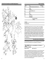
Metal Cutting
Cutting Bandsaw
Bandsaw
Metal
100090
W
AXMINSTER
W H I T E
Axminster Devon EX13 5HU UK
01297 33656
(International Dialling +44 1297 33656)
w w w. a x m i n s t e r. c o . u k
W
AXMINSTER
W H I T E
Index of Contents
Notes
Page No.
Index of Contents...............................................................................................................................................2
Declaration of Conformity………….………........……..…………................................................................. ..2
What’s in the Box………….………........……..…………..................................................................................... 3
General Instructions for 230v Machines...................................................................................... 3,4
Initial Assembly instructions......................................................................................................... 4,5
Mounting of the Machine................................................................................................................. 6
Specifications................................................................................................................................... 7
Parts Identification and Description................................................................................................ 8
Machine Illustration of the Metal Cutting Bandsaw.............................................................. 9,10,11
Parts Identification and Description (Continued)......................................................................... 12
Machine Illustration of the Metal Cutting Bandsaw (Continued)....................................... 13,14,15
Parts Identification and Description (Continued)......................................................................... 16
Machine Illustration of the Metal Cutting Bandsaw (Continued)................................................. 17
Setting up the Machine..................................................................................................................18
Operating instructions....................................................................................................................19
Routine Maintenance.................................................................................................................20,21
Illustrated Parts Breakdown for the Metal Cutting Bandsaw .............................................. ........22
Notes...............................................................................................................................................23
Declaration of Conformity
The undersigned, Can Tin authorised
by jiangsu jinfelds Power Tools Co., Ltd.
Xiejla Town 226644 Gaoyou City, Jiangsu Province
P.R. China
declares that this product:
Metal Saw
G4012
manufactured by jiangsu jinfelds Power Tools Co. is in compliance
with the following standards or standardisation documents in
accordance with Council Directives
EN 55014-1/1993 A2/1999
EN 55014-2/1997
EN 61000-3-2/1995 A14/2000
EN 61000-3-3/1995
02
23
What’s in the Box?
Illustrated Parts Breakdown for the Metal Cutting Bandsaw
Quantity
Item
Model Number
1 No.
Small Metal Cutting Bandsaw, with blade fitted.
2 No.
Pulleys
1 No.
Drive Belt
1 No.
Drive Belt and Pulley Cover
4 No.
Legs
4 No.
Rails
4 No.
Stretchers
1 No.
G4012
Extension Table
Pkt containing :Nuts, Bolts and Washers
Allen Keys
1 No. Manual
1 No. Guarantee Card
Having unpacked your machine and its accessories, please check the contents against the
equipment list ”What’s in the box”, if there are any discrepancies, please contact Axminster
Power Tool Centre using the procedures laid down in the catalogue. Please dispose of the
packaging responsibly; much of the material is bio-degradable. The machine and its accessories
will arrive coated with heavy corrosion preventative grease and greased wax paper. These will
need to be cleaned from the machine, its components and accessories prior to it being set up
and commissioned. Use coal oil, paraffin or a proprietary degreaser to remove the barrier grease.
Be warned, it will stain if you splash it on clothing etc.; wear overalls, coverall et al., rubber
gloves are also a good idea, as is eye protection if your cleaning process tends to be a little bit
enthusiastic. After cleaning, lightly coat the exposed metal surfaces of the machine with a thin
layer of light machine oil. N.B If you used paraffin/kerosene make sure you apply this thin film
sooner rather than later.
General Instructions for 230v Machines
Good Working Practices/Safety
The following suggestions will enable you to observe good working practices, keep yourself and
fellow workers safe and maintain your tools and equipment in good working order.
!
WARNING!!
KEEP TOOLS AND EQUIPMENT OUT OF THE REACH OF
YOUNG CHILDREN
Primary Precautions
Mains Powered Tools
These tools are supplied with a moulded 13 Amp. Plug and 3 core power cable. Before using the
tool inspect the cable and the plug to make sure that neither are damaged. If any damage is
visible have the tool inspected/repaired by a suitably qualified person. If it is necessary to replace
the plug, it is preferable to use an ‘unbreakable’ type that will resist damage on site. Only use a
13 Amp plug, and make sure the cable clamp is tightened securely. Fuse as required. If
extension leads are to be used, carry out the same safety checks on them, and ensure that they
are correctly rated to safely supply the current that is required for your machine. It is also good
policy to only use switched outlet supply points.
22
03
General Instructions for 230v Machines (Continued)
Routine Maintenance (Continued)
Work Place/Environment.
The machine is not designed for sub-aqua operation, do not use when or where it is liable to get wet. If the
machine is being used outside, and it starts to rain (unusual though this would be in U.K.), cover it up or
move it into the dry. If machine has got wet; dry it off as soon as possible, with a cloth or paper towel. Do
not use 230Va.c. powered machines anywhere within a site area that is flooded or puddled, and do not trail
extension cables across wet areas. Keep the machines clean; it will enable you to more easily see any
damage that may have occurred. Clean the machine with a damp soapy cloth if needs be, do not use any
solvents or cleaners, as these may cause damage to any plastic parts or to the electrical components.
!
Keep the work area as uncluttered as is practical, this includes personnel as well as
material.Under no circumstances should CHILDREN be allowed in work areas.
It is good practice to leave the machine unplugged until work is about to commence, also make sure to
unplug the machine when it is not in use, or unattended. Always disconnect by pulling on the plug body and
not the cable. Once you are ready to commence work, remove all tools used in the setting operations
(if any) and carry out a final check e.g. check drills are tight in their chucks, blades & tools are sharp and
correct type and size, power cables are free and will not snag when the machine is in use etc.
Make sure you are comfortable before you start work, balanced, not reaching etc.,
If the work you are carrying out is liable to generate flying grit, dust, chips or swarf, wear the appropriate
safety clothing, goggles, gloves, masks etc., If the work operation appears to be excessively noisy, wear
ear-defenders. If you wear your hair in a long style, wearing a cap, safety helmet, hairnet, even a
sweatband, will minimise the possibility of your hair being caught up in the rotating parts of the tool,
likewise, consideration should be given to the removal of rings and wristwatches, if these are liable to be a
‘snag’ hazard. Consideration should also be given to non-slip footwear, etc.
!
Do not work with cutting tools of any description if you are tired, your attention is wandering or
you are being subjected to distraction. A deep cut, a lost fingertip or worse; is not worth it!
!
Do not use this machine within the designated safety areas of flammable liquid stores or in areas
where there may be volatile gases. There are very expensive, very specialised machines for
working in these areas, THIS IS NOT ONE OF THEM.
Transition
gearbox
Bearing housing
Check that blades/drills etc., are the correct type and size, are undamaged and are kept clean and sharp,
this will maintain their operating performance and lessen the loading on the machine.
Above all, OBSERVE…. make sure you know what is happening around you, and USE YOUR COMMON
SENSE.
Motor casing
Initial Assembly instructions
Initial Assembly
Please take some time to read the section entitled “Identification and Parts Description”
to identify the various parts of your machine so that you are familiar with the terminology
we will use to enable you to set up and operate your Bandsaw safely and correctly.
The Stand
OIL
Oil
Overview
The stand is rectangular in shape. The bandsaw sits on the stand with the front of the machine
above the narrower side of the rectangle.
04
21
Routine Maintenance
Initial Assembly instructions (Continued)
Daily
Assembling the stand
•Keep the machine clean
•Check the saw blade for missing teeth and cracks in the fabric.
•Spray oil the metal surfaces
•Lightly oil the main rod of the vice and ease some oil into the locking lever housing.
•Check the security of the bolts holding the machine to the stand.
Monthly
•Remove the fastening bolt from the drive belt and pulley cover, open and check the
condition of the drive belt.
•Clean out the drive belt cover, bits of belt etc,etc. DO NOT USE OIL near the belts, but a
small amount can be carefully dripped on the bearing housing of the transition gearbox.
Close the cover and re-insert the bolt.
•Using an air line (and wearing goggles) blow out the motor casing.
Fig 1
B
Locate and identify the 4 legs, the rails (A) and the
stretchers for the stand, (B) and the packet containing
the coach bolts, washers and nuts.
The rails are almost symmetrical angle strips, the rails
have 4 holes punched in one face (2 at each end) and
are slightly shorter than the corresponding stretchers.
The shorter rails have an elongated slot cut in the
middle of the top face.
The stretchers are almost asymmetric angle strips,
both the long and the short stretchers have 2 holes
punched in one face (one each end).
A
Fig 2
C
Identify the two longest rails and the two longest
stretchers.
Assemble the two ‘long’ side frames for the stand. Bolt
the components together by putting the coach bolt
through the leg, through the rail or stretcher, secure
with washers and nut. Tighten the nut only ‘finger tight’
at this time. (See fig 1)
Six Monthly
•Remove the bolts securing the transition gearbox cover and check the grease
level.Repack as necessary, replace the cover.
C
When the two side frames have been assembled, select one, turn it upside down on a flat surface
and loosely bolt the ‘short side’ rails and stretchers (C) in place (See fig 2); attach the other side
frame, (keep the interleaving of the top surfaces of the rails the same, i.e. if the top face of the
narrow end of the stand rail is above the top face of the long side, keep it the same on both sides
and both ends). When all the components are assembled, using the flat surface as a reference,
tighten up all the nuts. Upright the frame and stand on the floor. (See fig 3)
Fig 3
Stand
20
05
Operating instructions
Mounting of the Machine
Locate the 2 No. M8 bolts etc., put to hand.
NOTE. Before lifting the bandsaw ensure that the transportation chain is secured. This will
preclude the possibility of the head moving whilst you lift it into place. (See fig 9c)
There are no hard and fast rules for using the metal cutting bandsaw. As a general guide the
harder the material, the slower the blade speed and the feed rate, conversely for softer material.
However, some materials cut better with a fast saw speed and a slow feed rate, likewise some
materials will require an cutting compound and others prefer it ‘dry’. I’m afraid you will need to
determine the best results empirically.
Lift the bandsaw onto the stand.
However, some hard and fast rules,
!
WARNING! The machine is heavy; you may require assistance.
1. Check the bandsaw switches Off at the end of the cut.
2. Ensure the work is held securely in the vice.
Fig 4a
3. Do not attempt to cut material that is not securely fastened in the vice.
4. Do not start the bandsaw if the blade is in contact with the workpiece.
5. Ensure the blade is in good condition.
6. Ensure the correct speed and feed rate are selected.
Bandsaw
7. Allow the machine to run up to full speed before attempting to cut.
8. Lower the blade slowly under hand control until it is in contact with the workpiece.
9. Ensure the offcut can fall free after being cut off, and will not jam against the blade.
10. If the material is long and heavy, support on either side of the saw.
Fig 4
Stand
Typ. 4 Feet
M8 bolt
Place the four feet approximately evenly about the corners, this should leave the two fixing holes
(approximately midway in the underside of the front and rear of the machine base) above the two
elongated slots in the front and rear rails of the stand. Introduce the M8 bolts (with washers
under the heads) through the slots, through the base and secure with washers and nuts. Tighten
firmly. Locate and identify the extension table and its fixings. Bolt to the side of the base
alongside the vice.
11. Use cutting compounds if required.
12. Do not wear gloves whilst actually operating the saw.
13. Do not attempt to pick up small offcuts immediately after they have been sawn (HOT).
14. If you are working in close proximity to the saw for long periods, wear ear defenders.
Fitting the Pulleys, the drive belt and the drive belt cover
Changing the feed rate spring tensioner
Locate and identify the pulleys the drive belt and the drive belt cover. Place the drive belt cover
over the two spindles, and secure (on the inside) using the M4 countersunk screw and washer
into the gearbox mandrel housing, and the external tab with the M6 caphead bolt and washer to
the threaded insert on the end of the motor plate pivot. Set the cover equidistant about the shafts
and tighten.
Identify the larger of the two pulleys, this fits (the large flange down) on the transition gearbox
shaft. Make sure the key is fitted in the keyway and push the pulley onto the shaft. Secure the
pulley in position using the caphead grubscrew which is aligned with the keyway, and located in
the middle groove. Fit the smaller pulley to the motor shaft, inverted (large flange up). Using a
straight edge (steel rule?) align the top surfaces of the pulleys and secure the pulley with the
similar grubscrew in the middle groove. Locate the belt tensioner, (See fig 8a) undo the lock nut
and unscrew the ‘push’ bolt to allow the motor to tilt forward. Fit the belt, make sure it is in
aligned grooves, tighten the belt by screwing in the ‘push’ screw; when the belt is tight, nip the
locking nut. Close the pulley cover and secure with the bolt.
06
Note- You may need a second person to assist you.
Remove the plastic “keeper” from the end of the spring tensioner, lift the saw as high as possible
to remove any tension on the spring. Slide the spring along the pivot axle and turn so that the
“captured” end of the spring will fit in the required hole - lower the saw and refit the plastic
keeper over the end of the spring. (See figs 6a,6b)
19
Setting up the Machine
The machine has been set up in the factory. If, however, you think the settings may have been
moved due to a ’knock’ or whatever, proceed to set the machine up as follows:-
!
Disconnect the machine from the mains supply.
Remove the front cover by undoing the 5 off M4 caphead bolts, remove them and the shakeproof
washers, place carefully aside.
Clean the machine completely.
Withdraw the blade guide assemblies to their furthest extremes, (leaving the maximum expanse
of blade exposed.) Open up the drive belt and pulley cover and turning one of the pulleys move
the blade and check the teeth and the fabric of the blade, (no cracks etc.), if all seems ok, check
the blade is under reasonable tension, and reconnect the machine to the supply. Stand on the
side of the machine away from the open frame and start the machine.
Allow it to run up to speed. Once the saw is running, carefully move to the front left side of the
saw and check the blade is tracking correctly, i.e. more or less in the centre of the wheel, not too
far off the front of the wheel. If the blade is running too far to the front, adjust the tracking by
screwing ‘in’ the tracking control bolt (see fig 9a),only adjust in small increments and wait for it to
take affect. If the tracking is too far to the rear (scuffing against the rim) ‘unscrew’ the tracking
control bolt NOTE if you unscrew the bolt be prepared to ‘tighten the blade’ a touch. Once the
blade is running correctly, switch the machine off. Disconnect the machine from the mains
supply. Replace the front cover.
Pull the saw down, turn the swivel base against the preset stop and using a good square set
against the rear jaw of the vice, check the blade of the square lies along saw blade. If it is out of
square, adjust the position of the swivel base, by adjusting the preset stop, until the correct angle
is reached. Check that the base remains in position when the base clamp is tightened. Adjust the
index pointer.
Specifications
Axminster No.
Metal Cutting Bandsaw
Makers Number:
Motor:
Blade Speeds:
Max cutting Capacities @ 90˚
Round Bar:
Square Bar:
Max Cutting Capacities @ 45˚
Round Bar:
Square Bar:
Blade Size:
Saw Body Swivel
Footprint:
Weight
100090
G4012
230v 50Hz 550W
20, 30, 50, M /min
110mm diameter
100mm x 150mm
70mm diameter
85mm x 65mm
1640L, 14 T.P.I., 0.65mm Thickness, 13mm Wide
0-45˚
915mm L x 575mm W x 1010mm H
70 Kgs
Noise level in accordance with DIN 45635
Offload:
Working:
!
> 60db(A)
60-65 db(A)
IT IS RECOMMENDED THAT YOU WEAR EAR PROTECTION
WHEN USING THIS MACHINE
Move the guide assemblies as close together as possible, leaving a small gap near the rear vice
jaw where you can stand a square. Stand the square on the floor of the vice with the blade of the
square up, check that the saw blade is vertical. The blades can be ‘twisted’ a little bit more, or
untwisted by loosening the main bolt that holds the bearing guide block onto the slides, moving
fractionally (there is only a small amount of ‘slop’ in the guide land and the groove between the
guide block assembly and the slide mechanism) and retightening.
Check the blade is pressed firmly between the two side rollers. If not, remove the safety cover
plates and adjust the rollers, by loosening the lock nuts (the top ones), and moving the bearing
using the eccentric cam profile (turn the bottom hexagons) of the mountings. DO NOT PUSH
THE BLADE OUT OF LINE by over adjusting (The blade should be in line with the groove in the
trust bearing). (See figs 9b & 9c)
When adjustment is complete re-tighten the lock nuts and replace the safety covers. Recheck
when everything is retightened. Reconnect the machine and run up to speed. Check everything
looks and sounds normal.
18
07
Parts Identification and Description
Machine Illustration of the Metal Cutting Bandsaw (Continued)
Please read through the section entitled Identification and Description of Parts, so that
you will be familiar with the terminology we will use in the manual, so that you can
identify the parts quickly and easily.
Mounting
guadrant
(See fig 5)
Front View
A quadrant casting, bolted thro’ to the base at the front apex, the quadrant
swivels about the bolt and is secured in position by a clamp bolt situated to
the rear of the quadrant which is engaged in a curved slot in the base.
Towards the rear of the casting are two trunnion castings, through which the
pivot axle of the saw is fitted.
Scale and
There is a scale decal set around the rear curved edge of the mounting
preset stop
quadrant, and a small adjustable arrow pointer fastened to the base as an
(See figs 6a & 6c) index mark, these will allow the swivel angle to be read. There is an
adjustable preset stop on the base which strikes against the right hand edge
of the mounting quadrant, this together with the scale and pointer can be
used to set the saw to cut at 90˚ to the plane of the vice.
Mounting
pivot yoke
(See figs 5 & 6b)
Mounted on one end of the pivot axle this casting mounts one side of the
main frame to the quadrant. There are three holes bored through the web of
this casting that will locate one end of the feed tension spring in different
positions, and therefore alter the reactive torsion in the spring, giving different
feed rates.
Main frame
(See fig 5)
This is the casting that mounts all the other components of the saw proper. It
is mounted at an incline on the quadrant, held on one side by a bearing
housing that fits to the pivot axle and on the other side by the mounting pivot
yoke. There is a rectangular box housing cast on the upper side of the frame
that mounts the components of the transition gearbox. There are also two
small trunnion castings at the rear of the upper side that mount the pivoting
axle for the motor mounting plate. There are various other housings machined
for mounting the wheel axle yokes, the blade guides, et al. There is also a
handle shape cast at the front of the frame to give a gripping point when
raising and lowering the saw.
Feed rate
spring
(See fig 6a)
This is a shaped torsion spring mounted concentrically on the pivot axle of
the saw. One end rests against the quadrant base and the other is fed
through one of the holes in the mounting pivot yoke web. The spring acts as
a counterbalance to the weight of the saw. The three holes give an adjustment
of the amount of torsion applied to the spring, therefore governing the ‘feed
rate’.
Stand assembly
Pulley and drive A pressed steel casing comprising an upper and lower section. The two
belt cover
sections are hinged together. The lower section is secured to the main frame
(See figs 10)
about the axles of the motor and the transition gearbox. The upper section is
the guard enclosure for the pulley towers and the drive belt. The two sections
are held closed by the hinge and a bolt.
Motor
(See fig 8)
Single phase motor rated at 550W. It is mounted on a plate which is in turn
mounted on an axle which allows it to pivot and act as a tensioning device for
the drive belt.
Rear View
08
17
Parts Identification and Description (Continued)
Height preset
(See fig 5)
A large bolt threaded into the front part of the quadrant. It strikes against a
lower protrusion on the main frame casting. Adjusting the height of the bolt
will govern the depth of cut of the saw blade. The Off switch striker can then
be adjusted to switch the saw off at this position if so required. As with the
switch striker, the preset height bolt is held in position by a lock nut.
Machine Illustration of the Metal Cutting Bandsaw
Blade tensioner
Handle
Fig 5
Typ. 5No. M4 clamphead bolts
Anchor/transport A short length of chain fixed to the base, that can be anchored to the saw
chain
frame, using a small ‘star handled’ bolt through one of the links. This will keep
(See fig 9d)
the saw anchored ‘down’ during transit.
Extended table
(See fig8)
A small pressed steel table that is bolted on to the side of the base alongside
the vice. It can act as a ‘catcher’ for the smaller lengths that can be cut off by
the saw.
Blade and
wheel cover
Pulley and drive belt cover
Blade
Clamping
lever handle
Lower limit stop
Rear jaw rod
Mounting
pivot yoke
Mounting Quadrant
16
Vice
Main frame
09
Machine Illustration of the Metal Cutting Bandsaw (Continued)
Machine Illustration of the Metal Cutting Bandsaw (Continued)
Fig 10a
adjustment
spring holes
(The drive belt has been
removed for clarity)
Motor pulley
‘Keeper’
Transition gearbox pulley
Mounting
pivot yoke
Fig 6
Fig 6a
Fig 6b
Slide & move to
change feed rate
Fig 10b
Drive belt
cover
Fig 6c
Feed rate spring
Adjustable
preset stop
Fig 10c
Clamping bolt
Scale
Adjustable
arrow pointer
10
Drive belt cover bolt
Fig 10
15
Machine Illustration of the Metal Cutting Bandsaw (Continued)
Fig 9a
Front wheel mounting
axle assembly
Fig 9b
Front guide assembly
Machine Illustration of the Metal Cutting Bandsaw (Continued)
Fig 7a
Blade tensioner
Blade guide
assembly
Lock nuts
Front wheel
Tracking control bolt
Blade guide
assembly
Safety cover
Hexagon adjuster
Fig 9c
Driver wheel
Fig 9
Anchor/transport chain
Fig 9e
Fig 7
Safety cover
Fig 7b
Fig 9d
Mounting rod
Auto off striker
Preset length stop
14
11
Parts Identification and Description (Continued)
Drive belt
tensioner
(See fig8a)
There is a bolt fitted through a hole bored and threaded in the front edge of
the motor plate. Driving this bolt ‘down’ will cause it to ‘push’ against the
main frame and force the motor plate to turn on its axle, forcing the gearbox
and motor axle further apart and therefore tightening the belt. Once the belt is
tensioned the bolt is held in position with a lock nut.
Transition
gearbox
(See fig 8)
This is the gearbox that transposes the motor drive though 90 degrees to the
saw wheel and gears the speed down to a usable rate.
Wheels
(See fig 7)
The wheels are 185mm diameter, tyred and rim edged. The driver wheel is
fixed in plane as it is mounted directly on the transition gearbox shaft. The
front wheel is mounted on a tilting axle yoke that allows the wheel to be
tilted so that the blade can be tracked.
Blade tensioner
(See fig 7)
This is a threaded rod with a ‘star handle’ moulded at one end. The rod is fed
through a bushing in the end of the main frame as far as the handle, with a
‘skid’ washer to aid turning. The threaded end is engaged in a threaded dog
mounted on the front wheel yoke. Tightening (screwing in) the rod will pull the
yoke and therefore the front wheel towards the end of the main frame thus
tightening the blade.
Blade guides
(See figs 8)
(See figs 9,a,b,c)
Blade and
wheel cover
(See fig 5)
On/Off switches
(See fig 8b)
Vice
(See fig 5)
12
The guides fulfil two roles, the first of which is to twist the blade the final
complement angle to achieve vertical to the base, and the second is to hold
the blade in position during cutting. There are three guides in each set. The
two side guides which perform the ‘twist’ and keep the blade in line, and the
thrust guide, which maintains the up/down position of the blade between the
side guides. The thrust guide has a groove ground into it to help prevent the
blade ‘skidding’ away from its cutting line. The guides are mounted in slot
housings machined in the main frame and are adjustable along the exposed
section of the blade. There are safety covers attached to the guide
assemblies that maintain cover over the blade when the guides are moved
The position of the rear guide set is normally locked using a cap head bolt,
against the position of the vice, the front guide set is locked with a ‘star
handled’ bolt against the clearance required for the material being cut.
Machine Illustration of the Metal Cutting Bandsaw (Continued)
Drive belt tensioner
Front wheel
mounting axle
assembly
Fig 8a
Front guide
star handle
lock
Transport chain
anchor
Front guide
Clamping handle
Fig 8
Transition
gearbox
Rear guide
Rear guide locking bolt
This is the main cover for the saw frame. A pressed steel plate held onto the
face of the frame with 5 No. M4 caphead bolts and shake proof washers.
The On/Off switch enclosure is mounted on the swivel quadrant so that it
maintains position with the saw. There is a striker on the main frame of the
saw (See fig 9e) that depresses the Off button when the saw has reached the
lower limit of its cut and therefore gives an Auto Off function. The striker is
adjustable (a threaded bolt and a lock nut) so that the switch off point can be
accurately set. The switches are marked as standard with ‘I’ indicating ‘On’
and ‘O’ indicating Off. The switch has a NVR function so that the saw will not
inadvertently remain On if there is a power disruption.
A good capacity KWIK action vice mounted directly to the base. The clamping
jaw is free to move on a long rod, that is clamped and ‘squeezed’ forward by
the action of the clamping lever handle on the side of the vice. The vice is
bored to accept a length of rod, which acts as a mounting bar for the preset
length stop. (See fig 9d) The preset length stop can be positioned along the
bar and locked in position using an M6 Bristol Handle.
Motor
Rear jaw rod
Extended table
On
Off
Fig 8b
NVR switch
13