Download Samsung ML-2552W Specifications
Transcript
LASER PRINTER ML-2550 ML-2551N ML-2552W SERVICE LASER PRINTER Manual CONTENTS 1. Precautions 2. Reference Information 3. Specifications 4. Summary of product 5. Disassembly and Reassembly 6. Alignment and Adjustments 7. Troubleshooting 8. Exploded Views and Parts List 9. Block Diagram 10. Connection Diagram Copyright(c) 2003.09 * This service manual is a property of Samsung Electronics Co., Ltd. Any unauthorized use of Manual can be punished under applica ble international and/or domestic law. * This service manual is also provided on the web, the ITSELF system Samsung Electronics Co., Ltd. http://itself.sec.samsung.co.kr © Samsung Electronics Co.,Ltd. September 2003 Printed in Korea. VERSION NO. : 1.00 CODE : JC-0106A Precautions 1 1. Precautions The cautions in the below are items needed to keep in mind when maintaining and servicing. Please read carefully and keep the contents in mind to prevent accidents while servicing and prevent any damages to the damage. 1.1 Warning for safety. (1) Request the service by qualified service person. The service for this machine must be performed by a service person who took the additional education of this field. It is dangerous if unqualified service person or user tries to fix the machine. (2) Do not rebuild it discretionary. Do not attach or change parts discretionary. Do not disassemble, fix, and rebuilt it. If you do, printer will not work and electric shock or a fire can be occurred. (3) Laser Safety Statement The Printer is certified in the U.S. to conform to the requirements of DHHS 21 CFR, chapter 1 Subchapter J for Class 1(1) laser products, and elsewhere, is certified as a Class I laser product conforming to the requirements of IEC 825. Class I laser products are not considered to be hazardous. The laser system and printer are designed so there is never any human access to laser radiation above a Class I level during normal operation, user maintenance, or prescribed service condition. Warning >> Never operate or service the printer with the protective cover removed from Laser/Scanner assembly. The reflected beam, although invisible, can damage your eyes. When using this product, these basic safety precautions should always be followed to reduce risk of fire, electric shock, and injury to persons. CAUTION - INVISIBLE LASER RADIATION WHEN THIS COVER OPEN. DO NOT OPEN THIS COVER. VORSICHT - UNSICHTBARE LASERSTRAHLUNG, WENN ABDECKUNG GE FFNET. NICHT DEM STRAHL AUSSETZEN. ATTENTION - RAYONNEMENT LASER INVISIBLE EN CAS D OUVERTURE. EXPOSITION DANGEREUSE AU FAISCEAU. ATTENZIONE - RADIAZIONE LASER INVISIBILE IN CASO DI APERTURA. EVITARE L ESPOSIZIONE AL FASCIO. PRECAUCION - RADIACION LASER IVISIBLE CUANDO SE ABRE. EVITAR EXPONERSE AL RAYO. ADVARSEL. - USYNLIG LASERSTR LNING VED BNING, N R SIKKERHEDSBRYDERE ER UDE AF FUNKTION. UNDG UDSAETTELSE FOR STR LNING. ADVARSEL. - USYNLIG LASERSTR LNING N R DEKSEL PNES. STIRR IKKE INN I STR LEN. UNNG EKSPONERING FOR STR LEN. VARNING - OSYNLIG LASERSTR LNING N R DENNA DEL R PPNAD OCH SP RREN R URKOPPLAD. BETRAKTA EJ STR LEN. STR LEN R FARLIG. VARO! - AVATTAESSA JA SUOJALUKITUS OHITETTAESSA OLET ALTTIINA N KYM TT M LLE LASERS TEILYLLE L KATSO S TEESEEN. Service Manual Samsung Electronics 1-1 Precautions 1.2 Caution for safety 1.2.1 Precaution related noxious material There is a possibility to get harm from noxious material if you ignore the below information. (1) Do not touch the damaged LCD. This PRINTER has LCD in control panel. Noxious liquid to human body exists in the LCD. If it gets into your mouth, immediately see a doctor. If it gets into eyes or on skin, immediately wash it off for more than 15 minutes with flowing water and see a doctor. (2) The toner in a printer cartridge contains a chemical material, which might harm human body if it is swallowed. Please keep children out of the toner cartridge. 1.2.2 Precaution related electric shock or fire It is possible to get electric shock or burn by fire if you don't fallow the instructions of the manual. (1) Use exact voltage. Please do use an exact voltage and wall socket. If not, a fire or an electric leakage can be caused. (2) Use authorized power cord. Do use the power cord supplied with PRINTER. A fire can occur when over current flows in the power cord. (3) Do not insert many cords in an outlet. If you do, a fire can be occurr due to flow over current over flow in an outlet. (4) Do not put water or extraneous matter in the PRINTER. Please do not put water, other liquid, pin, clip, etc. It can cause a fire, electric shock, or malfunction. If it happens, turn off the power and remove the power plug from the outlet immediately. (5) Do not touch the power plug with wet hands. When servicing, do remove the power plug from outlet. And do not insert or take off it with wet hands. Electric shock can be occur. (6) Caution when inserting or taking off the power plug. The power plug has to be inserted completely. If not, a fire can be caused due to poor contact. When taking off the power plug, do grip the plug and take it off. If grip the line and pull over, it could be damaged. This could cuase a fire or electric shock. (7) Management of power cord. Do not bend, twist, or bind it and place other materials on it. Also, do not fix it with staples. If the power cord gets damage, a fire or electric shock can be caused. A damaged power cord must be replaced immediately. Do not repair the damaged part and reuse it. A repaired part with plastic tape can be occurred a fire or electric shock. Do not spread chemicals on the power cord. Do not spread insecticide on the power cord. A fire or electric shock can be occurred due to thinner(weak) cover of the power cord. (8) Check whether the power outlet and the power plug are damaged, pressed, chopped, or on fire. When such poor conditions are found, repair it immediately. Avoid pressure or cut when moving the machine. (9) Caution when thundering, and being flash of lightening. It causes a fire or electric shock. Take the power plug off when thundering. Do not touch cable and device when thundering and being flash of lightening. (10) Avoid places where there is moisture or dust. Do not install the printer in a place where lots of dusts or humidifier are around. A fire can occur. A plug part needs to be cleaned well with dried fabric to remove dust. If water drops are dripped on the place cover with dust, a fire can occur. (11) Avoid direct sunlight. Do not install the printer near to window where directly contacts to the sunlight. If the machine contacts sunlight long time, the machine cannot work properly because inner temperature of the machine is getting higher. A fire can be caused. (12) Turn off the power and take off the plug when a smoke, strange smell, or sound from the machine. If you keep using it, a fire can occur. (13) Do not insert steel or metal piece inside/outside of the machine. Do not put steel or metal piece into a ventilator. An electric shock can happen. 1-2 Service Manual Samsung Electronics Precautions 1.2.3 Precaution related handling the machine. If you ignore this information, you get hurt and machine could be damaged. (1) Do not install unit on uneven surfaces or slanted floors. Please confirm that unit is correctly balanced after installation. Machine may fall over when itis not balanced correctly. (2) Be careful not to insert a finger or hair in the rotating unit. Be careful not to insert a finger of hair in the rotating unit (motor, fan, paper feeding part, etc) while the machine is operating. Once it happens, you could harm. (3) Do not place any containers of water/chemical or small metals. If those are got into the inner side of machine, a fire or electric shock can occur. (4) Do not install machine in areas where moisture or dust exists. For example, do not install machine near open windows, damage maybe caused by these conditions. (5) Do not place a candle, burning cigarettes, and etc. on the machine. Do not install it near to a heater. A fire can occur. 1.2.4 Precaution when assembly/disassembly When replace parts, do it very carefully. Do memorize the location of each cable before replace parts for reconnecting it afterwards. Do memorize. Please perform the below before replace or disassemblying any parts. (1) Check the contents stored in the memory. All the information will be erased after replace main board. The information needed to keep has to be written down. (2) Remove printer cables and power cord. (3) Take off printer cables and power code connected to printer. (4) Do use formal parts and same standardized goods when replacing parts.Must check the product name, part cord, rated voltage, rated current, operating temperature, etc. (5) Do not give an over-force when release or tighten up the plastic parts. (6) Be careful not to drop the small parts such as screws in the printer. (7) Be careful not to change the location of small parts such as screws when assembling and disassembling. (8) Do remove dust or foreign matters completely to prevent fire of tracking, short, or etc. (9) After finished repair, check the assembled state whether it is the same as before the repair or not. Service Manual Samsung Electronics 1-3 Precautions 1.3 ESD Precautions Certain semiconductor devices can be easily damaged by static electricity. Such components are commonly called “Electrostatically Sensitive (ES) Devices”, or ESDs. Examples of typical ESDs are: integrated circuits, some field effect transistors, and semiconductor “chip” components. The techniques outlined below should be followed to help reduce the incidence of component damage caused by static electricity. Caution >>Be sure no power is applied to the chassis or circuit, and observe all other safety precautions. 1. Immediately before handling a semiconductor component or semiconductor-equipped assembly, drain off any electrostatic charge on your body by touching a known earth ground. Alternatively, employ a commercially available wrist strap device, which should be removed for your personal safety reasons prior to applying power to the unit under test. 2. After removing an electrical assembly equipped with ESDs, place the assembly on a conductive surface, such as aluminum or copper foil, or conductive foam, to prevent electrostatic charge buildup in the vicinity of the assembly. 3. Use only a grounded tip soldering iron to solder or desolder ESDs. 4. Use only an “anti-static” solder removal device. Some solder removal devices not classified as “anti-static” can generate electrical charges sufficient to damage ESDs. 5. Do not use Freon-propelled chemicals. When sprayed, these can generate electrical charges sufficient to damage ESDs. 6. Do not remove a replacement ESD from its protective packaging until immediately before installing it. Most replacement ESDs are packaged with all leads shorted together by conductive foam, aluminum foil, or a comparable conductive material. 7. Immediately before removing the protective shorting material from the leads of a replacement ESD, touch the protective material to the chassis or circuit assembly into which the device will be installed. 8. Maintain continuous electrical contact between the ESD and the assembly into which it will be installed, until completely plugged or soldered into the circuit. 9. Minimize bodily motions when handling unpackaged replacement ESDs. Normal motions, such as the brushing together of clothing fabric and lifting one’s foot from a carpeted floor, can generate static electricity sufficient to damage an ESD. 1-4 Service Manual Samsung Electronics Reference Information 2 2. Reference Information This chapter describes the reference information for applying this training manual, and it is consisted of the tool list, the abbreviation table, the outline of model, and so on. 2.1 Tool for Troubleshooting The following tools are recommended for safe and smooth troubleshooting described in this service manual. 1 DVM(Digital Volt Meter) Standard : Indicates more than 3 digits. 4 Driver Standard : "-" type, "+" type (M3 long, M3 short, M2 long, M2 short). 5 Tweezers Standard : For general home use, small type. 2 Electronic Scale Standard : Equipment to check the weight of consumables(toner cartridge) supplied by Samsung Electronics. (The gram unit can be measured.) 6 Cotton Swab Standard : For general home use, for medical ser-vice 7 Spring Hook Standard : For general use 3 Software(Driver) installation CD ROM 8 Cleaning Equipments a IPA(Isopropyl Alcohol)dry cloth or a soft stuff neutral detergent Keep your hands not to be touched when you disassemble and reassemble PBA ASS'Y, such as the main board, SMPS, HVPS. Service Manual Samsung Electronics 2-1 Reference Information 2.2 Acronyms and Abbreviations The table in the below explains abbreviations used in this service manual. The contents of this service manual are declared with abbreviations in many parts. Please refer to the table. 2-2 AC Alternating Current AP Access Point IPA Engineers. Inc Isopropy Alcohol ASIC Application Specific Integrated Circuit IPM Images Per Minute ASSY assembly LAN local area network BIOS Basic Input Output System lb pound(s) CMOS Complementary Metal Oxide Semiconductor LBP Laser Beam Printer LCD Liquid Crystal Display CN connector LED Light Emitting Diode CON connector LSU Laser Scanning Unit CPU Central Processing Unit MB megabyte dB decibel MHz megahertz dbA decibelampere MPF Multi Purpose Feeder dBM decibel milliwatt NIC Network Interface Card DC direct current NVRAM nonvolatile random access memory DCU Diagnostic Control Unit OPC Organic Photo Conductor DPI Dot Per Inch PBA Printed Board Assembly DRAM Dynamic Random Access Memory PCL DVM Digital Voltmeter Printer Command Language , Printer Control Language ECP Enhanced Capability Port PDL Page Discription Language EEPROM Electronically Erasable Programmable Read Only Memory PPM Page Per Minute EMI Electro Magnetic Interference EP electrophotographic EPP Enhanced Parallel Port F/W firmware GDI graphics device interface GND ground HBP Host Based Printing HDD Hard Disk Drive HV high voltage HVPS High Voltage Power Supply I/F interface I/O Input and Output IC integrated circuit IDE Intelligent Drive electronics or Imbedded Drive Electronics IEEE Institute of Electrical and Electronics PS Post Script PTL Pre-Transfer Lamp Q-PID Quick Printer Initiating Device Q ty quantity RAM Random Access Memory ROM Read Only Memory SCF Second Cassette Feeder SMPS Switching Mode Power Supply SPGP Samsung Printer Graphic Processor SPL Samsung Printer Language Spool Simultaneous Peripheral Operation Online SW switch sync synchronous or synchronization USB Universal Serial Bus WECA Wireless Ethernet Compatibility Alliance Service Manual Samsung Electronics Reference Information 2.3 Selecting a Location Select a level,stable place with adequate space for air circulation.Allow extra space for opening covers and trays. The area should be well-ventilated and away from direct sunlight or sources of heat,cold,and humidity.Do not set the printer close to the edge of your desk or table. CLEARANCE SPACE • • • • Front : 482.6 mm (enough space so that trays can be removed) Back : 320 mm (enough space to allow opening of the rear cover) Right :100 mm Left :100 mm (enough space for ventilation) Service Manual Samsung Electronics 2-3 Reference Information 2.4 The Sample Pattern for the Test The sample pattern shown in below is the standard pattern used in a factory. The contents of the life span and the printing speed are measured with the pattern shown in below. (The picture in the manual is 70% size of the actual A4 size.) 2.4.1 A4 5% Patten 2-4 Service Manual Samsung Electronics Reference Information 2.4.2 A4 2% Patten Service Manual Samsung Electronics 2-5 Reference Information 2.4.3 A4 LSA 5% Patten 2-6 Service Manual Samsung Electronics Reference Information 2.6 Wireless LAN • This product uses a printing function with a wireless LAN, which is an option. - The wireless LAN function uses a frequency instead of connecting LAN cable to connect data to an access point for print. - For a wireless LAN connection, an AP is needed, It is possible to use wireless LAN onnection with wired LAN. Also, if AP is installed in an office or at home, the wireless LAN function can be simply used. • Types of desk top PC (or Lap top) that uses the wireless LAN. Division Basic type Recommend type CPU Over PENTIUM 233M PENTIUM 300MHz MEMORY Over 64MB Over 128MB VIDEO CARD Over 800X600 Over 1024X768 OS Over WINDOWS 98 Over WINDOWS ME INTERFACE CARD A product has a certificated mark of Wi-FiTM • About the certificated mark of Wi-FiTM - The Wi-FiTM is a registered trademark of WECA (Wireless Ethernet Compatibility Alliance). Over 50 of a wireless LAN companies are member of it. The most of main wireless networking companies are attending and the main companies are Lucent technologies, Cisco, Intel/Symbol, 3Com, Enterasys (Cabletron), Compaq, IBM, Nokia, Dell, Philips, Samsung electronic, Sony, Intersil, and so on. This mark certifies mutual compatibility among product has Wi-FiTM (IEEE 802.1) and it is certified as a standard of a wireless LAN market. Service Manual Samsung Electronics 2-7 Reference Information 2-8 Service Manual Samsung Electronics Specifications 3 3. Specifications Product specifications are subject to change without notice.See below for product specifications. 3.1 General Specifications ITEM DESCRIPTION Print Method Non-impact Electro-photography Development system Non-Magnetic, Mono-Component Toner Transfer system Conductive roller transfer Fuser Unit(Toner fix) Pressure and Heating with Lamp Print Speed 24 PPM : A4 size 25 PPM : Letter size Resolution True 600 X 600 DPI Addressable 1200 X 1200 DPI Source of Light Laser diode (LSU : Laser Scanner Unit) Warm-Up Time Power-on boot : 50 seconds or less First Print Time 12 seconds or less Feed Method Cassette & Manual , Option Feeder(SCF) Media Size 76mm * 128mm(3 * 5”) to 216mm * 356mm(8.5 *14”) Media Thickness Cassette : 16 ~ 28 lb, Manual : 16 ~43lb Dimension(W X D X H) 386 X 436 X 326 mm / 15.2 X 17.2 X 12.8 inch (without options) Weight Net : 13.7 Kg Gross : 17.1 Kg Acoustic Noise Stand by : Less than 35 dB Printing: Less than 53 dB Sleep mode : Background Noise Power save mode Enable Toner save mode Enable Consumption Parts Retard Roller Optional Parts 100,000 Pasges Transfer Roller 100,000 Pasges Fuser Assembly 125,000 Pasges SCF Paper Capacity : 500 Sheets Network Printing Ethernet 10/100 base TX (ML-2550:Optional Protocols : TCP/IP, SPX/IPX, Ethertalk, SNMP, ML-2551N : Basic) HTTP1.1, DLC/LLC 32MB RAM Buffer for faster graphics performance 2MB Flash Memory for upgrade Throughput : 200 ~ 300K TCP/IP SDRAM DIMM 16, 32, 64, 128MB 100PIN SDRAM DIMM 802.11b Wireless LAN IEEE802.3b supportT (ML-2552W Basic) Speed : 11, 5.5, 2, 1 Mbps Protocol : CSMA/CD Operation range : 30m(Indoors), 150m(Outdoors) Service Manual Samsung Electronics 3-1 Specifications 3.2 Controller Specification ITEM DESCRIPTION Processor(CPU) SPGPi + Power PC 266 MHz Memory FLASH ROM(PROGRAM +Postscript ) : 2MB flash * 2 RAM : 32MB (Expandable to 160MB) Option DIMM module : 16,32,64,128MB (SDRAM) 100Pin SDRAM DIMM (Samsung Printer Only) EEPROM(NVRAM) : 512byte Emulation PCL6 : win 3.1/95/98/ME/NT/2000/XP Postscript Level3 : win 95/98 PPD , win NT4.0 PPD , Mac PPD PCL5e : Linux Interface Parallel : IEEE 1284 Bidirectional Parallel - Modes supported : Compatible,Nibble,Byte,ECP USB(without HUB mode) -USB 2.0 compliant -12 Mbps 1 port Serial : RS-232C Network Interface : option for ML-2550 -10/100 Base TX -10/100 Base TX & 802.11b Wireless LAN (option for ML-2551N) Interface switching Automatic Interface time-out 5min(Max.) Font 45 Scalable Font , 1 Bitmap Font ,Postscript 3 internal font 136 3.3 Electrical Specification ITEM Input Voltage Power Consumption DESCRIPTION REMARK Nominal input voltage 220-240 VAC / 100~127VAC Input voltage range 198-255 VAC/ 90~135VAC Nominal frequency 50/60 MHz Frequency tolerance +3Hz 450W Avg or less (with SCF) Idling : 100W Avg or less Power Save : 20W Avg or less 3.4 TONER Cartridge (Developer) ITEM Life span DESCRIPTION Starter: 5,000 pages REMARK A4 Size, LSA 5% pattern, SIMPLEX Running : 10,000 pages Developing 3-2 Non-magnetic Contact Developing Charging Conductive Roller Charging Toner supply Method Exchange the Developer Toner checking sensor Enable Ozone 0.1PPM or less Style Single cartridge Service Manual Samsung Electronics Specifications 3.5 Environmental Condition ITEM OPERATING STORAGE Temperature 10~30 oC(50-90 oF) -20~40 oC (-4~104 oF) Humidity 20~80%RH 10~80%RH 3.6 Paper Handling Specifications >> Input Paper Size 1ST CASSETTE 2ND CASSETTE MP TRAY DUPLEX A4 PAPER 210 X 297 mm PAPER SIZE O O O O Letter 216 X 279(8.5 X 11") O O O O Folio(Legal13") 216 X 330(8.5 X 13") O O O O Legal(Legal14") 216 X 356(8.5 X14") O O O O Executive 184 X 267((7.25 X10.5") O Statement 140 X 216(5.5 x8.5") ISO B5 176 X 250 O O JIS B5 182 X257 O O A5 148 X 210 O O A6 105 X148 O No.10 Env 105 X 241(4.15 X 9.5") O O O Monarch Envelope 98 X191(3.87 X 7.5") O DL Envelope 110 X 220(4.33 X 8.66") O C5 Envelope 162 X 229(6.38 X 9.01") O C6 Envelope Transparency(OHP) 114 X 162(4.49 X 6.38") A4 or Letter O O Label paper A4 or Letter O O : Enable >> Input capacity ITEM DESCRIPTION Cassette 500sheets MP tray Paper Option Cassette 100 sheets Transparencies 50 sheets Envelopes 10 sheets Labels 25 sheets 500sheets >> Output capacity ITEM DESCRIPTION Face Down 250 sheets Face UP 100 sheets Service Manual Samsung Electronics 3-3 Specifications 3-4 Service Manual Samsung Electronics Summary of product 4 4. Summary of Product This chapter describes the functions and operating principal of the main component. 4.1 Printer Components 4.1.1 Front View Top output tray (Face down) Output Support Control Panel Top Cover Toner cartridge Multi-Purpose Tray Tray1 Control board cover (500-sheet paper feeder) Optional Tray2 Paper level indicator (needed to access the control board to install printer options) (500-sheet paper feeder) Service Manual Samsung Electronics 4-1 Summary of Product 4.1.2 Rear View Power switch Wireless network antenna port (ML-2550, ML-2551N:Option ML-2552W:Standard) Network port (ML-2550:Option ML-2551N, ML-2552W: Standard) USB port Rear output tray (Face up) Parallel port Power receptacle Optional Tray2 cable connector 4-2 Service Manual Samsung Electronics Summary of product 4.1.3 Control Panel The control panel on the top right side of your printer has the display and the nine buttons. Display : displays the printer status and job in progress. Buttons 4.1.3.1 Display Message Ready Offline Printing XXX * xxx is the current Description • The printer is on-line and ready to print. • If you press On-Line/Continue ,the printer switches to off-line. • The printer is off-line and cannot print. • If you press On-Line/Continue ,the printer switches to on-line. • The printer is printing. • If you want to cancel printing,press Cancel . emulation. Sleeping... • The printer is in Power Save mode, consuming less power. When a print job is received from the computer or if any button is pressed,the printer switches to on-line. Service Manual Samsung Electronics 4-3 Summary of Product 4.1.3.2 Buttons Button Description • Press to switch between on-line and off-line. • In menu mode,press to return to ready mode. You can check the printer status according to the button backlight. Green On The printer is on-line and can receive data from the computer. Blinking • When the backlight slowly blinks,the printer is receiving data from the computer. • When the backlight fast blinks,the printer is receiving and printing data. If you want to pause printing, switch the printer to off-line. Orange On The printer stops printing due to a major error.Check the display message. Blinking A minor error occurs and the printer is waiting an error to be cleared.Check the display message.When the problem is cleared,the printer resumes printing.If you want to ignore this warning,press this button. Off • The printer is off-line and cannot print. • The printer is in Power Save mode. When data is received,it switches to on-line. • Press to enter menu mode. • In menu mode,press to scroll through the menus. In menu mode,press to select the displayed submenu item or confirm the changed setting. You can see the selected value marked with *. In menu mode,press to scroll through submenu items or setting options. Pressing moves you to the next option and pressing sends you back to the previous option. • Press to cancel the current print job. • In menu mode,press to return to ready mode. In menu mode,press to go back to the upper menu level. Press to enable or disable Toner Save mode. • If the button backlight is on,the mode is enabled and the printer uses less toner to print a document. • If the button backlight is off,the mode is disabled and the printer will print in the normal quality. For more information on the Toner Save mode. Press to enable or disable the double-sided printing. • If the button backlight is on,the printer print on both sides of paper with long edge binding. • If the button backlight is off,the double-side printing is disabled and the printer prints on one side of paper. Note : The double-sided printing setting in the printer driver overrides that of the control panel. 4-4 Service Manual Samsung Electronics Summary of product 4.1.3.2 Using Control Panel Menus A number of menus are available to make it easy for you to change printer settings. Accessing Control Panel Menus You can control your printer from the printer ’s control panel. You can also set the control panel menus while the printer is in use. 1. Press the Menu button until you see the desired menu on the bottom line of the display or Press the scroll button until the desired menu item displays on the bottom line. 2. Press the Enter button 3. Press the scroll button 4. Press the Enter button to access the menu. until the desired menu item displays on the bottom line. to confirm the selected item. 5. If the selected menu item has submenus,repeat steps 3 and 4. 6. Press the scroll button 7. Press the Enter button until the desired setting option displays on the bottom line or enter the required value. to save your input or selection. An asterisk (*) appears next to the selection on the display, indicating that it is now the default. 8. To exit the menu,press the Upper Level button repeatedly,or the Cancel button . After 60 seconds of inactivity (no key has been pressed), the printer automatically returns to ready mode. NOTE : Duplicate print settings that are selected in the printer driver override the settings on the control panel. Service Manual Samsung Electronics 4-5 Summary of Product 4.1.3.3 Overview of Control Panel Menus The control panel menus are used to configure the printer for your environment. The control panel provides access to the following menus. Information Paper Layout Configuration Menu Map Demo Page PS3 Font List PCL Font List EPSON Fonts Tr ay Source Media Size Custom Width Custom Heigh Media Type Tr ay Chaining Orientation Duplex Duplex Margin Simplex Margin Copies Setup LCD Language Emulation Power Save Auto Continue Jam Recovery Altitude Adj. Auto CR Job Time Out RS-232C Maintenance Printer Graphics Default Set Current Job Resolution Image Enhance Toner Save Density PCL PostScript EPSON Typeface Symbol Lines Pitch Point Size Courier Print PS. Error Font Auto Wrap Character Set Character Tab. LPI Pitch NETWORK Config Network Config TCP/IP DHCP IP Address Set IP Address Subnet Mask Gateway BOOTP 4-6 AppleTalk Netware Config Netware AUTO EN_8023 EN_II EN_8022 EN_SNAP Reset Network Default Set Print Net CFG RX Level Service Manual Samsung Electronics Summary of product 4.1.3.4 Special Features Your new printer is equipped with special features that improve the print quality,giving you a competitive edge. You can: Print with excellent quality and high speed • You can print at 1200 dots per inch (dpi).See page 5.25. • Your printer prints 21 pages-per-minute (Letter size), 20 pages-per-minute (A4 size). Handle paper flexibly • A 100-sheet Multi-Purpose Tray supports letterheads, envelopes,labels,transparencies,custom-sized materials,postcards,and heavy paper. • Standard 500-sheet input tray (Tray1)and optional 500-sheet input tray (Tray2)supports all standard sizes of paper. • Two output tray;select either the top output (face-down)or the rear output tray (face-up)for the most convenient access. • Straight-through paper path capability from the Multi-Purpose Tray to the rear output tray. Create professional documents • You can customize your documents using Watermarks, such as “Confidential.” ) ( • Print Booklets .This feature enables you to easily print the pages required to create books.Once printed,all you have to do is to fold and staple the pages. • Print Posters .The text and pictures of each page of your document are magnified and printed across the selected sheet of paper.After the document has printed,trim off the white edges of each sheet.Tape the sheets together to form a poster. Save your time and money • This printer allows you to use Toner Save mode to save toner. • You can print on both sides of the paper to save paper (double-sided printing ). • You can print multiple pages on one single sheet of paper to save paper (N-Up printing ). • Preprinted forms and letterheads can be printed on plain paper. • This printer automatically conserves electricity by substantially reducing power consumption when not printing. • This printer meets Energy Star guidelines for energy efficiency. Service Manual Samsung Electronics 4-7 Summary of Product Expand the printer capacity • This printer has 32 MB of memory which can be expanded to 160 MB. • Network interface enables network printing.You can add the optional network interface card to ML-2550. ML-2551N and ML-2552W comes with a built-in network interface,10/100 Base TX.ML2552W also has a wireless network interface. * PostScript 3 Emulation IPS-PRINT_Printer language Emulation © Copyright 1995-2003,Oak Technology,Inc.,All rights reserved * 136 PS3 fonts Contains UFST and MicroType from Agfa Monotype Corporation. Print in various environments • You can print in Windows 95/98/Me/NT 4.0/2000/XP . • Your printer is compatible with Linux and Macintosh . • Your printer comes with both the Parallel and USB interfaces. You can also use a network interface .ML-2551N and ML-2552W comes with a built-in network interface,10/100 Base TX.ML-2552W also has a wireless network interface. But, you need to add the optional network interface card to ML2550. Printer Features The table below lists a general overview of features supported by your printer. Features ML-2550 ML-2551N ML-2552W IEEE 1284 STANDARD STANDARD STANDARD USB 2.0 STANDARD STANDARD STANDARD Network Interface OPTION STANDARD STANDARD Wireless LAN OPTION OPTION STANDARD STANDARD STANDARD STANDARD PostScript Emulation 4-8 Service Manual Samsung Electronics Summary of product 4.2 System Layout 8 5 4 6 H/R OPC P/R Transfer ransfer Roller 7 2 Pick up Roller(MP) Regi Roller Pick up Roller 3 Retard Roller 1 1 Cassette 5 LSU 2 Duplex Unit 6 Fuser 3 MPF 7 Main Motor 4 Toner Cartridge 8 Exit Motor Service Manual Samsung Electronics 4-9 Summary of Product 4.2.1 Feeding It is consists of a basic cassette, an MP tray for supplying different types of media : envelope, label special paper, duplex unit, and parts related to paper transferring. 1) Separation method Separate it from the finger mounted to the cassette side guide and apply retard roller that uses a spring clutch. A feed roller uses an electronic clutch to control driving power. 2) Basic cassette It takes a center loading method and applies 'both side finger separating method.' It means that there is a paper sensor, but a paper size is detected after detecting the first paper by software. Both the side guide and the rear guide can be adjusted for for various types of papers from A5 to legal size paper. It has a paper existence sensing function (Capacity: 500 sheets of general paper), paper arranging function, various size papers accepting function, SCF paper path function, and displaying function of paper remaining amount. In the front side, there is a paper level indicator. 3) Pick-up roller It has functions such as a paper pickup function, driving control function, paper feeding function, and removing electronic static function. 4) Retard roller It takes an arrangement method which uses a stopper roller and a weight without electric actuator.It has paper separating function, driving control function, and multi feeding prevention function. 6) Registration roller It has a paper arranging function, paper transferring function, paper detecting function, jam removing function, and so on. 7) MP tray It has a paper arranging function, paper transferring function, jam removing function, and so on. It uses rubbing pad method to feed 100 sheets of general papers and 100 envelops. It is possible to extend to 300mm for accepting a legal size paper. 8) Duplex unit It has paper transferring function, paper guide function, jam removing function, paper sensing function, and main board supporting function. It is designed for basic attachment, and the duplex feeding takes a side feeding method. Usable papers are A4, letter, and legal size paper. For removing a jam occurred in a front part, it is designed to open a cassette and a guide. It is designed to open a rear cover to remove a jam in a rear part. If a face up tray is open, the duplex option cannot be used. 9) SCF (Second Cassette Feeder) It is the same method with the main cassette, and the capacity is 500 sheets. It has a separate driving mechanism and feeds only A4, letter, and legal size paper. It is designed for a common use with a main cassette, but it cannot be attached with the main cassette. 4-10 Service Manual Samsung Electronics Summary of product 4.2.2 Transfer It consists of a PTL (Pre-transfer Lamp) and a transfer roller. A PTL sheds light on an OPC drum, lowers an electric potential of an OPC drum's surface, and improves the efficiency of the transfer. A transfer roller transfers toner on an OPC drum to the paper. Life span: Print over 100,000 sheets (In 15~30(C) 4.2.3 Driver Ass'y By driving the motor, the system takes power. It is consisted of a main motor for feeding and a toner cartridge, and sub-motors for fuser and duplex reverse turn. 4.2.4 Fuser It is consisted of a heat lamp, heat roller, pressure roller, thermistor and thermostat. It sticks the toner on a paper by heat and pressure to complete the printing job. 1) Thermostat When a heat lamp is overheated, a Thermostat cuts off the main power to prevent over-heating. 3) Heat roller The heat roller transfers the heat from the heat lamp to apply a heat on the paper. The surface of a heat roller is coated with Teflon, so toner does not stick to the surface. 4) Pressure roller A pressure roller mounted under a heat roller is made of a silicon resin, and the surface also is coated with Teflon. When a paper passes between a heat roller and a pressure roller, toner adheres to the surface of a paper permanently. 5) Items for safety Protecting device for overheating - 1st protection device: Hardware cuts off when overheated - 2nd protection device: Software cuts off when overheated - 3rd protection device: Thermostat cuts off main power. Safety device - A fuser power is cut off when a front cover is opened - Maintain a temperature of fuser cover's surface under 80(C for user, and attach a caution label at where customer can see easily when customer open a rear cover. 4.2.5 LSU (Laser Scanner Unit) It is the core part of the LBP which switches from the video data received to the controller to the electrostatic latent image on the OPC drum by controlling laser beam, exposing OPC drum, and turning principle of polygon mirror. The OPC drum is turned with the paper feeding speed. The /HSYNC signal is created when the laser beam from LSU reaches the end of the polygon mirror, and the signal is sent to the controller. The controller detects the /HSYNC signal to adjust the vertical line of the image on paper. In other words, after the /HSYNC signal is detected, the image data is sent to the LSU to adjust the left margin on paper. The one side of the polygon mirror is one line for scanning. Service Manual Samsung Electronics 4-11 Summary of Product 4.2.6 Toner Cartridge By using the electronic photo process, it creates a visual image. In the toner cartridge, the OPC unit and the toner cartridge unit are in a body. The OPC unit has OPC drum and charging roller, and the toner cartridge unit has toner, supply roller, developing roller, and blade (Doctor blade) - Developing Method: Non magnetic 1 element contacting method - Toner: Non magnetic 1 element shatter type toner - The life span of toner: 10,000 sheets (LSA Pattern/A4 standard) - Toner remaining amount detecting sensor: Yes - OPC Cleaning: Cleaning blade type - Management of disusable toner: Collect the toner by using Cleaning Blade - OPC Drum protecting Shutter: Yes - Classifying device for toner cartridge: ID is classified by interruption of the frame channel. 3 2 Cleaning Roller 0.20mW -470V Max -1.5KV 4 -850V -250V 1 -650V 8 Cleaning Blade 5 6 +4.2kV -100V 7 <Toner Cartridge Layout> 4-12 Service Manual Samsung Electronics Summary of product 4.3 Main Board Main controller part is organized with Asic (SPGPi) part, Memory part, and Engine interface part, and it is functions as a Bus control, I/O handling, Drivers, and PC interface by CPU. Memory access has program memory (supports 32bit operation) and working memory (supports 32bit operation). DC_Motor CN8 Fan LSU CN15 CN10 DC_Fan CN21 Cartridge CN6 Panel CN4 Cover Open Sensor CN20 Network Card Slot CN9 PTL CN17 Engine PBA CN18 USB Port CN2 P1284 Port CN3 DC_Motor CN11 Joint PBA CN14 SCF CN1 Memory (RAM) CN12 Flash Memory CN16 DCU CN7 Service Manual Samsung Electronics 4-13 Summary of Product 4.3.1 ASIC (SPGPi) >> Power PC Comapatible Interface >> 3 Memory Bus Architectur ROM Bus, Primary DRAM Bus, Seconday SDRAM Bus for Band Buffer >> Direct connected to 4 ROM Banks 32 MByte Address Space per Bank Burst Capability Programmable Timing per Bank >> Direct connected to max 6 I/O Banks of ROM Bus 64 MByte Address Space per Bank Programmable Timing per Bank >> Direct connected to max 3 I/O Banks of DRAM Bus for DMA 8 KByte Address Space per Bank Programmable Timing per Bank >> Direct connected to max 9 DRAM / SDRAM Banks Support EDO or FPM Type DRAM and SDRAM Max 128 MByte Address Space per Bank Programmable Timing to Control DRAM / SDRAM A.C Characteristics Support Self Refresh for Data Retention >> Direct connected to 1 SDRAM Banks using Secondary Bus for Band Buffer Support SDRAM only Max 512 KByte Address Space Programmable Timing to Control SDRAM A.C Characteristics Support Self Refresh for Data Retention Bus Traffic Sharing using Secondary Bus >> Graphic Coprocessor Core for Banding support of Printer Languages Support up to 256 Bit Block Transfer Scan Line Transfer Polygon Filling Enhanced Graphic Order compared to SPGP, SPGPe+ Access to Secondary Bus >> Parallel Port Interface Controller DMA based or Interrupt based Operation Support IEEE Standard 1284 Communication >> UART 4 Independent Full Duplex UART (Interrupt Based Operation Only) max 16 Byte FIFO to Handle SIR Bit Rate Speed >> DMA 3 Channel General Purpose DMA Controller for High Speed I/O 8 bit, 16 bit, 32 bit Data Transfer Mode Support 4-14 Service Manual Samsung Electronics Summary of product >> Timer 3 Independent Programmable Timer Watch Dog Timer for S/W Trap and Tone Generator for MFP Application >> RSH Fully H/W Rotator, Scaler and Halftoner Variable Image Scaler and Image Halftoning Unit for PCL6 >> Compression / Decompression 3 Different Kinds of Codec Algorithm jCodec : Powerful T.85 JBIG Algorithm for Bi Level Image Compression gCodec - Simplified JBIG Algorithm for Band Compression, coupled with GEU - Access to Secondary Bus HCT : Halftone Compression Technology (Byte Run-Length Type) Independent Compression & Decompression Data Path of Each Codec >> Printer Video Controller 2 Different Kind of Printer Video Controller (Selected by S/W) High Performance DMA based Interface to Printer Engine PVC : Printer Video Controller without RET Algorithm HPVC - Printer Video Controller with RET Algorithm - Access to Secondary Bus >> Package : 352 pin BGA >> Power Core : 2.5 V IO : 3.3 V Service Manual Samsung Electronics 4-15 Summary of Product 4.3.1.1 SPGPi Internal Block Diagram PowerPC IO (6 Ba n k ) PCI Briddge Flash Mem Font(4Bank) CPU I/F Clock Gen. ROM(4ch) Controller Primary System Bus Processor Bus I/O(6ch) Controller Reset Gen. RSH Timer jCodec IEEE1284 HCT ITC (5CH) ECI Secondary System Bus Tone Gen. UART (4CH) gCodec Extermal DMAC(3ch) GEU SDRAM(9ch) Controller HPVC SDRAM Secondary DRAM (4Mbits) DRAM(9ch) Controller PVC SSB Arbiter DRAM PSB Arbiter SPGPi 4-16 Service Manual Samsung Electronics Summary of product 4.3.2. Memory part >> Flash Memory It stores the System Program. • Capacity: 2M Byte * 2 • Access Time : 70 nsec >>SDRAM It is used as Swath buffer, System working memory area, etc. when printing. • Capacity: 32M Byte (Basic), upto 160M Byte (Option) • DIMM : 16MB / 32MB / 64MB /128MB • Type : SDRAM 100MHz/133MHz , 16bit >>ROM DIMM It supports the option ROM DIMM 1 Slot for supporting the expanding Memory. • Capacity : 8MByte (Max) • Access Time : 70nsec 4.3.3. RESET Circuit After printer power is ON and 50~200 ms are passed, the reset signal from RESET IC (XC61FN3112MR) resets various IC such as the CPU, Memory, etc. to prevent malfunction of the set by setting the initial value of port. 4.3.4. ClOCK Circuit Basically, it consists of the Crystal (12.5MHz) and Capacitor (27pF) which is connected to the crystal in parallel, and it is inputted to the MCLLK_Signal via the CY25814. The purpose of the adding SY25814 is substitution of EMI. 4.3.5. INTERFACE Part >>IEEE1284 It supports the IEEE 1284 B Type Connection, and the protocol supports the IPP, ECP, Compatibility, Byte, and Nibble mode. >>USB2.0 USB2.0 Compliant, 480Mbps 1 port >>Network • Option : Ethernet 10/100 Base TX • Protocol : SPX/IPX, TCP/IP,Appletalk, SNMP, HTTP 1.1, DLC/LLC >>Panel • LCD : 16Char. * 2 Line / Back-light(Yellow) • Key : 9 Key • LED : 3 LED The UART method is used for the controller and panel interface, and the HR 48C50 Holtak Micom is used Service Manual Samsung Electronics 4-17 Summary of Product 4.3.6. Sensor input circuit 4.3.6.1. Paper Empty Sensing The Paper empty sensor (Photo Interrupter) on the engine board informs the state of paper to LPEC1 whether it is empty or not by operation of the actuator. When cassette is empty, it detects the fact by reading the GPIO3_1 of LPEC1, and then displays the fact on the LCD panel. 4.3.6.2. MP Sensing By operation of the MP Sensor (Photo Interrupter) on frame and Actuator, it informs the state of paper to CPU whether it is empty or not. It reads the IP5 sec_DRAM(K26) of CPU for recognizing paper in MP, and paper is fed from MP if there is. 4.3.6.3. Paper Feeding When paper passes the actuator on the feed sensor part, it detects the signal of Photo interrupter, informs the paper feeding state to CPU, and then sprays the image data after certain time. If it doesn't detect the feed sensor within 1 sec. after paper is fed, paper jam0 (LPEC1 GPIO3_2) is occurred. (Displays on the LCD panel) 4.3.6.4. Toner Remain Sensing The Toner cartridge terminal is mounted to the joint board located on frame. When the toner cartridge is inserted, it is adhered to the contacting point of the joint board to sense whether the toner cartridge exists or not, ID, amount of toner, and so on. 4.3.6.5. Paper Exit Sensing It detects paper state whether paper gets out from the set with operation of exit sensor on the engine board and actuator on the frame. Paper detects the on/off time of exit sensor by reading LPEC1 GPIO3_6, and the normal operation or jam information is informed to the CPU. The paper JAM2 is informed. (Displays the state on LCD panel) 4.3.6.6. Cover Open Sensing The Cover open sensor is located on the front cover. After the front cover is opened, +24V and +5V (DC fan, solenoid, main motor, polygon motor part of LSU, HVPS, LSU Laser diode), which is supplied to each unit, is cut off. 4.3.6.7. DC FAN/Solenoid Driving Circuit A fan driving circuit is driven by a transistor and a controller which is in the LPEC. It is automatically turned off when a machine turns to sleep mode. There are two solenoids, and it is driven by an MP signal and a paper pick-up signal. 4.3.6.8. Motor Driving Circuit A main motor (BLDC) drives a feeding and developing unit and an exit motor (Step) drives a Fuser and an Exit ass'y. When printing with a duplex function, it rotates the Exit Motor to a normal/reverse direction. It controls by dividing the acceleration section, standard speed section, and reducing speed section. A BLDC Motor is operated by a clock and enable signal, and a Step Motor is managed with an A3977 driver IC. 4-18 Service Manual Samsung Electronics Summary of product 4.4 SMPS & HVPS board The SMPS and HVPS are in one united board. The SMPS part supplies the DC power to the system. It takes either 110V or 220V and outputs the +3.3V and +24V to supply the power to the main board. The HVPS part creates the high voltage of THV/MHV/Supply/Dev and supplies it to the toner cartridge part for making the best condition to display the image. The HVPS part takes the 24V and outputs the high voltage for THV/MHV/BIAS, and the outputted high voltage is supplied to the toner, OPC cartridge, and transfer roller. Exit Sensor HVPS Inlet Main PBA Fuser Service Manual Samsung Electronics 4-19 Summary of Product 4.4.1. HVPS(High Voltage Power Supply) 1) Transfer high voltage (THV (+)) - Function: It is a voltage that transfers toner on an OPC Drum to paper. - Output voltage: MAX +4.2 KV +/- 5% (Duty is changeable, Not loading) - 1.7KV +/- 15% (When cleaning, 200MOhm - It transfers toners with (+) polarity of transfer roller to an OPC Drum. - Error type: IF THV (+) is not outputted, it causes a low density due to toner on an OPC Drum if it is not transferred to paper. It is possible that over-flow occurs if toner is piled up in a toner vessel continuously. 2) Charge voltage (MHV) - Function: It is a voltage that charges a surface of OPC to -750V~-900V. - Output voltage: -1.35KV~1.5KV DC +/- 50V - Error type: IF MHV is not outputted, toner overflows and reaches to an OPC drum if surface of an OPC is not charged. A black paper is printed out when it happens. 3) Cleaning voltage: THV (-) - Function: It removes contamination at a rear by sending (-) polarity in a transfer roller to OPC drum to take toner. - Output voltage: A change range is large according to a load because there is no feedback control =(-600V~1200V) - Error type: An error due to contamination of toner on a backside of printing paper. 4) Developing voltage (DEV) - Function: It is a voltage that develops toner with electronic potential difference of the section exposed by LSU (Laser Scanning Unit). * When printing, exposing voltage of OPC is -250V and exposing voltage of DEV is -470V. Therefore, toner with (-) polarity is developed on an exposed section. - Output voltage: -380V~500DC +/- 20V - Error type: a) If DEV is GND, a density gets extremely low. b) When DEV is floating due to instable of terminal’s contacting point, and etc., density gets extremely high. 5) Supplying voltage (SUP) - Function: It is a voltage that supplies toner to a developing roller. - Output voltage: -560V~680V DC +/- 50V (Use AENER, Gearing of DEV - (-)180V more than DEV) - Error type: a) When SUP is GND, density gets extremely low. b) If SUP is floating due to instable of terminal’s contacting point, and etc., density gets extremely low that it is hard to catch up with eyes. 6) OPC Ground ZENER voltage - Function: It is a voltage to prevent an image contamination under the condition of low temperature and low humidity environment. - When a set prints without an output voltage, -100V is maintained on OPC ground. (-100V ZENER diode is connected to OPC ground) - Error type: a) When ZENER diode is - 0V, there is no serious image problem in general environment, but in low temperature and low humidity environment, it is possible that a contamination occur on entire image b) When ZENER diode is disconnected, a blank page is printed out. (It is the same case as when a ZENER diode is disconnected to OPC ground.) 4-20 Service Manual Samsung Electronics Summary of product 4.4.2. SMPS(Switching Mode Power Supply) It is the power source for the whole system. It is an independent module so it is possible to use for common use. It is mounted at the bottom of the set. It consists of the SMPS part, which supplies the DC power for driving the system, and the AC heater control part, which supplies the power for fuser. SMPS has three outputting channels (3.3V, 5V and +24V). There are three kinds of power, 120V exclusive (America), 220V exclusive (Europe), and 220V for china (nations with instable power supply). >>AC Input • Inputting rated voltage : AC 220V ~ 240V AC 100V ~ AC 127V • Inputting voltage fluctuating range: AC 198V ~ 255V AC 90V ~ 135V • Rated frequency : 50/60 Hz • Frequency fluctuating range : 47 ~ 63 Hz • Inputting voltage: Under 5.5Arms/2.5Arms >>Rated Power Output NO 1 2 Item Channel name CONNECTOR PIN 3 Rated outputting voltage 4 5 6 7 8 Maximum outputting voltage Peak loading voltage Ripple noise voltage Maximum output Peak output CH1 +3.3V CON 3 3.3V PIN: 12, 14 GND PIN: 16, 18 3.3V ± 5% (3.2 ~ 3.4V) 1.5 A 1.5 A 200mVp-p 5W 5W CH2 +5V CON 3 5V PIN : 8 GND PIN: 7 +5V ± 5% (4.75 ~ 5.25V) 0.5 A 0.5 A 100mVp-p 2.5 W 2.5 W CH3 +24.0V CON 3 24V PIN: 2, 4, 6 GND : 7, 8, 10 +24V ± 5%, -5% (21.6 ~ 26.4V) 0.5 A 0.5 A 500mVp-p 84 W 84 W Remark 1ms 1ms >>Consumption Power NO 1 2 3 Item Stand-By PRINTING Sleep-Mode CH1 (+3.3V) 0.6 A 1.0 A 0.4 A CH2 (+5V) 0.25A 0.25 A 0.01 A CH3 (+24V) 0.4 A 2.0 A 0.4 A System AVG : 100 Wh AVG : 450 Wh AVG : 20 Wh >>Length of Power Cord: 1830 ± 50mm >>Power Switch : Use Service Manual Samsung Electronics 4-21 Summary of Product >>Feature • Insulating resistance : over 50MΩ(at DC 500V) • Insulating revisiting pressure Must be no problem within 1min. (at 1500Vzc, 10mA) • Leaking voltage : under 3.5mA • Running voltage : under 50A peak (at 25°C, Cold start) Under 60A peak (in other conditions) • Rising Time : Within 2sec • Falling Time : over 20ms • Surge: Ring Wave 6KV-500A (Normal, Common) >>Environment Condition • Operating temperature range : 0°C~50°C • Maintaining temperature range : -25°C~85°C • Maintaining humid range : 10% ~90% RH • Operating atmospheric pressure range: 1 >>EMI Requirement CISPR ,FCC, CE, MIC, C-Tick, >>Safety Requirement IEC950 UL1950, CSA950, C-UL, TUV, Semko, iK, CB, CCC(CCIB),GOST, EPA 4.4.3. Fuser AC Power Control Fuser (HEAT LAMP) gets heat by using AC power. The AC power controls the switch with the Triac, a semiconductor switch. The 'On/Off control' is operated when the gate of the Triac is turned on/off by Photo triac, which is insulting part. In the other words, the AC control part is passive circuit, so it turns the heater on/off with taking signal from engine control part. When the 'HEATER ON' signal is turned on at engine, the LED of PC1 (Photo Triac) takes the voltage and flashes. From the flashing light, the Triac part (light receiving part) takes the voltage, and the voltage is supplied to the gate of Triac and flows into the Triac. As a result, the AC current flows in the heat lamp, and heat is occurred. On the other hand, when the signal is off, the PC1 is off, the voltage is cut off at the gate of Triac, the Triac becomes off, and then the heat lamp is turned off. >>Triac (THY1) feature:12A,600V SWITCHING >>Phototriac Coupler (PC3) • Turn On If Current : 16mA • High Repetive Peak Off State Voltage : Min 600V 4-22 Service Manual Samsung Electronics Summary of product 4.5 Engine F/W 4.5.1 Feeding If feeding from a cassette, the drive of the pickup roller is controlled by controlling the solenoid. The on/off of the solenoid is controlled by controlling the general output port or the external output port. If feeding from a manual feeder, decide to insert the paper according to the operation of the manual sensor, and by driving the main motor, insert the paper in front of the feed sensor. While paper moves, occurrence of jam is judged as below. (Refer to the [6.2 Paper Transfer rout]) 4.5.1.1 Jam 0 • After picking up, paper cannot entered due to paper mis-feed. • After picking up, paper entered but it cannot reach to the feed sensor in certain time due to slip, etc. • After picking up, if the feed sensor is not on, repack up. After repacking up, if the feed sensor is not on after certain time, it is Jam 0. - It is a status that the leading edge of the paper doesn’t pass the feed sensor. • Even though the paper reaches to the feed sensor, the feed sensor doesn’t turn on. - It is a status that the leading edge of the paper already passed the feed sensor. 4.5.1.2 Jam 1 • After the leading edge of the paper passes the feed sensor, the tailing edge of the paper cannot pass the feed sensor after certain time. (The feed sensor cannot be Off) • After the leading edge of the paper passes the feed sensor, the paper cannot reach the exit sensor after certain time. (The exit sensor cannot be On) - The paper exists between the feed sensor and the exit sensor. 4.5.1.3 Jam 2 • After the tailing edge of the paper passes the feed sensor, the paper cannot pass the exit sensor after certain time. 4.5.1.4 Duplex Jam 1 A leading edge of a paper didn't reach a Duplex Sensor after certain time passes. 4.5.1.5 Duplex Jam 2 After a leading edge of the paper passes the Duplex Sensor, the rear edge of the paper does not pass a Duplex Sensor within a certain time. 4.5.2 Drive A main motor (BLDC) drives a feeding and developing unit and an exit motor (Step) drives a Fuser and an Exit ass'y. When printing with a duplex function, it rotates the Exit Motor to a normal/reverse direction. It controls by dividing the acceleration section, standard speed section, and reducing speed section. A BLDC Motor is operated by a clock and enable signal, and a Step Motor is managed with an A3977 driver IC. 4.5.3 Transfer The charging voltage, developing voltage and the transfer voltage are controller by PWM (Pulse Width Modulation). The each output voltage is changeable due to the PWM duty. The transfer voltage admitted when the paper passes the transfer roller is decided by environment recognition. The resistance value of the transfer roller is changed due to the surrounding environment or the environment of the set, and the voltage value, which changes due to the environments, is changed through AD converter. The voltage value for impressing to the transfer roller is decided by the changed value. Service Manual Samsung Electronics 4-23 Summary of Product 4.5.4 Fusing The temperature change of the heat roller’s surface is changed to the resistance value through the thermistor. By converting the voltage value, which impressed to the resistance, to the digital value through the AD converter, the temperature is decided. The AC power is controlled by comparing the target temperature to the value from the thermistor. If the value from the thermistor is out of the controlling range while controlling the fusing, the error stated in the table occurs. (For the domestic model, the Q-PID method has been applied.) Error Open Heat Error Description When warming up, it has been lower than 68°C over 28 seconds LCD Display Engine Fuser Error Lower Heat Error • Standby: It has been lower than 130°C over 10 seconds • Printing: - 3 consecutive page; it has been 20°C lower than the fixed fusing temperature over 7 seconds. Engine Fuser Low Heat Error Over Heat Error It have been higher than 230°C over 10 seconds Engine Fuser Over Heat Error 4.5.5 LSU The LSU is consisted of the LD (Laser Diode) and the polygon motor control. When the printing signal occurs, it turns the LD and drives the polygon motor. When the receiving light part detects the beam, Hsync occurs. When the polygon motor speed becomes a normal, LReady occurs. If two conditions are satisfied, the status bit of the LSU controller register becomes 1 to be judged that the LSU is ready. If two conditions are not satisfied, the error shown in below occurs. Error Polygon motor error Description When the polygon motor’s speed doesn’t become a normal Hsync error The polygon motor’s speed is normal, but the Hsync signal is not created. 4-24 LCD Engine LSUError HSYNC Error Service Manual Samsung Electronics Summary of product Service Manual Samsung Electronics 4-25 Disassembly and Reassembly 5 5. Disassembly and Reassembly 5.1 General Precautions on Disassembly When you disassemble and reassemble components, you must use extreme caution. The close proximity of cables to moving parts makes proper routing a must. If components are removed, any cables disturbed by the procedure must be restored as close as possible to their original positions. Before removing any component from the machine, note the cable routing that will be affected. Releasing Plastic Latches Many of the parts are held in place with plastic latches. The latches break easily; release them carefully. To remove such parts, press the hook end of the latch away from the part to which it is latched. Whenever servicing the machine, you must perform as follows: 1. Check to verify that documents are not stored in memory. 2. Be sure to remove the toner cartridge before you disassemble parts. 3. Unplug the power cord. 4. Use a flat and clean surface. 5. Replace only with authorized components. 6. Do not force plastic-material components. 7. Make sure all components are in their proper position. Service Manual Samsung Electronics 5-1 Disassembly and Reassembly 5.2 Transfer Roller 1. Open the Open Cover. 2. Hold the lever at both ends of the roller, then remove the roller. Transfer Roller Open Cover Holder <Cautions When Replacing a Transfer Roller> * Do not grab the transfer roller shown in picture (A). It may cause a malfunction due to a foreign object. * Hold the both sides of the transfer roller shown in picture (B) when replacing it. Transfer Roller Transfer Roller (A) 5-2 (B) Service Manual Samsung Electronics Disassembly and Reassembly 5.3 MPF Ass’y 1. Open the MPF Ass’y. 3. Remove the Tray Links from the MP Cover Tray Link MPF Ass’y 2. Remove two springs from the Knock Up Plate Ass’y. 4. Push the MP Cover and remove it as shown below. MP Cover NOTICE : Do not separate the spring from the MP Pick-up rack for convenience of assembling. Locate the hook section of the spring that is connected to the Knock Up Plate ass'y as shown in the picture below toward the outside for convenience of assembling. 5. Remove MP Cover in the direction of arrow Tray Link MP Pick Up Rack Knock Up Plate Ass’y Service Manual Samsung Electronics 5-3 Disassembly and Reassembly 5.4 Retard Ass’y 1. Remove two screws. Then lift the Roller Ass’y, as shown below. Notice: When you reassemble the Retard Roller ass’y make sure that the let and of the Retard roller fits into the Retard shaft. Retard Ass’y 5-4 Service Manual Samsung Electronics Disassembly and Reassembly 5.5 Cover-Right 1. Pull the Cassette out of the printer. Cassette 2. Remove two screws and take out the Right Side. Cover-Right Service Manual Samsung Electronics 5-5 Disassembly and Reassembly 5.6 Main PBA 1. Before you remove the Main PBA you should remove: - Cover-Right (Refer to the 5.5) 4. Remove two screws and take out the Dummy Bracket. 2. Unplug all the connectors, as shown below. Dummy Bracket 3. The connectors are located as shown below. 5. Remove six screws and take out the Main PBA. DC_Motor CN8 Fan LSU CN15 CN10 DC_Fan Cartridge CN21 CN6 Panel CN4 Cover Open Sensor CN20 Network Card Solt CN9 PTL CN17 Engine PBA CN18 USP Port CN2 P1284 Port CN3 DC_Motor CN11 Main PBA Joint PBA CN14 Memory (RAM) CN12 5-6 SCF CN1 Flash Memory CN16 DCU CN7 NOTICE : One screw among the screws is locked on the Engine Shield.(Refer to 5.25.3) Service Manual Samsung Electronics Disassembly and Reassembly 5.7 Main Drive Ass’y 1. Before you remove the Right Side Ass'y, you should remove: - Cover-Right (Refer to the 5.5) 5. Remove six screws and take out the Main Drive Ass’y. 2. Unplug the two Connectors after you remove the two screws and take out the Cover Joint PBA. Main Drive Ass’y Cover Joint PBA 3. Unplug the two connectors from the Main PBA and the Connector PBA. 6. When separating the Main Motor ass'y, disconnect the connector form the Main PBA, remove 4 screws, and then remove the Main Motor ass'y. Main Motor Ass’y 4. Remove the E-ring and take out the Clutch. Clutch E-ring Service Manual Samsung Electronics 5-7 Disassembly and Reassembly 5.8 Connector PBA 1. Before you remove the Connector PBA, you should remove: - Cover-Right (Refer to the 5.5) 2. Unplug all of the connectors from the Connector PBA and take it out. 3. The connectors are located as shown below. MP Solenoid Clutch MP Empty Main Solenoid S/W Main PBA Connector PBA 5-8 Service Manual Samsung Electronics Disassembly and Reassembly 5.9 Solenoid 1. Before you remove the Connector PBA, you should remove: - Cover-Right (Refer to the 5.5) - Main Drive Ass’y (Refer to the 5.7) 4. Remove two screws and take out the Main Solenoid. 2. Unplug the MP Solenoid Harness and the Main Solenoid Harness from the Connector PBA. Main Solenoid 3. Remove two screws and take out the MP Solenoid. NOTICE : It is not necessary to disassemble the Main Drive Ass’y to remove the MP Solenoid MP Solenoid Service Manual Samsung Electronics 5-9 Disassembly and Reassembly 5.10 Cover-Left 1. Pull the Cassette out of the printer. Cassette 3. Remove two screws and take out the Cover-Left Cover-Left 2. Remove two screws and take out the Right Side. Cover-Rear 5-10 Service Manual Samsung Electronics Disassembly and Reassembly 5.11 DC Fan 1. Before you remove the DC Fan, you should remove: - Cover-Right (Refer to the 5.5) - Cover-Left (Refer to the 5.10) 3. Remove one screw for taking out the Stopper, and then take out the DC Fan. DC Fan 2. Unplug the two Connectors from the Connector PBA. Stopper 4. Remove two screw for taking out the Stoppers, and then take out the Fan. Fan CN15 DC_Fan CN21 Fan Stopper Service Manual Samsung Electronics 5-11 Disassembly and Reassembly 5.12 Rear Cover 1. Open the Rear Cover, and then take out the Stopper. 2. Remove the Rear Cover in the direction of arrow. Rear Cover 1 Tie Stopper 2 5-12 Service Manual Samsung Electronics Disassembly and Reassembly 5.13 Top Cover 1. Before you remove the Top Cover, you should remove: - Cover-Right (Refer to the 5.5) - Cover-Left (Refer to the 5.10) 4. Unlatch both ends of the Top Cover. 2. Open the MPF Ass’y, the Rear Cover, the Open Cover. 5.Unlatch the hook and take out the Top Cover. Top Cover 3. Unplug the two Connectors after you remove the three screws from the Main PBA. Key Panel 6. Remove 7 screws, and then take out the LCD Panel and the Key Panel. Cover Open Panel CN4 Cover Open Sensor CN20 LCD Panel Key Panel Service Manual Samsung Electronics 5-13 Disassembly and Reassembly 5.14 Open Cover 1. Before you remove the Open Cover, you should remove: - Top Cover (Refer to the 5.13) 4. Release the lock as shown below and lift up the Sensor Cap. 2. Remove two screws and take out the Stopper. Stopper Micro Switch PBA Sensor Cap 3. Take out the Open Cover as shown below. Open Cover 5.15 Inner Cover 1. Before you remove the Inner Cover, you should remove: - MPF Ass’y (Refer to the 5.3) - Top Cover (Refer to the 5.13) 2. Remove two screws and take out the Inner Cover. Inner Cover 5-14 Service Manual Samsung Electronics Disassembly and Reassembly 5.16 Fuser Ass’y 1. Before you remove the Fuser Ass’y, you should remove: - Rear Cover (Refer to the 5.12) 4. Remove one screw, and then take out the Thermistor from the Fuser Ass’y. Thermistor 2. Remove four screws and take out the Fuser Ass’y. Fuser Ass’y 3. Remove two screws and take the Thermostat out of the Fuser Ass’y. 5. Remove two screws and take the Halogen Lamp out of the Heat Roller. Thermostat Halogen Lamp Nut Nut Service Manual Samsung Electronics 5-15 Disassembly and Reassembly 6. Remove three screws and take out the Gear bracket. 8. Take out the Heat Roller as shown below. Heat Roller Gear Bracket Bushing Fuser Gear 7. Remove two screws and divide the Fuser into two parts. 9. Take out the Pressure Roller as shown below. Fuser Upper Unit Pressure Roller Bushing 5-16 Service Manual Samsung Electronics Disassembly and Reassembly 5.17 Exit Drive 1. Before you remove the Exit Driver, you should remove: - Top Cover (Refer to the 5.13) 3. Remove three screws and take out the Exit Driver Ass’y. 2. Unplug the Exit Driver Harness from the Main PBA. 4.Remove two screws and take out the Exit Motor. Exit Motor Service Manual Samsung Electronics 5-17 Disassembly and Reassembly 5.18 Exit Roller 1. Before you remove the Exit Roller, you should remove: - Top Cover (Refer to the 5.13) 4 Take out the Exit Gear as shown below. 2. Take the Actuator out. Bearing Actuator Exit Gear 5. Take out the Duplex Exit Roller as same method. 3. Remove the Exit Roller and Bearing as shown below. Duplex Exit Roller Bearing Exit Roller 5-18 Service Manual Samsung Electronics Disassembly and Reassembly 5.19 LSU 1. Before you remove the LSU, you should remove: - Cover-Right (Refer to the 5.5) - Cover-Left (Refer to the 5.10) - Top Cover (Refer to the 5.5) 4. Remove three screws and take out the LSU. LSU 2. Release the lock as shown below. 3. Remove the Exit Roller Rack in the direction of arrow. Service Manual Samsung Electronics 5-19 Disassembly and Reassembly 5.20 Toner Sensor Board 1. Before you remove the Toner Sensor Board, you should remove: - Top Cover (Refer to the 5.13) - LSU (Refer to the 5.19) 4. Remove 3 screws and take out the LSU Lower Cover. LSU Lower Cover 2. Unplug 5 Harness from the Toner Sensor PBA. 3. Take out the Toner Sensor PBA. Toner Sensor PBA HV Small Spring 5-20 Service Manual Samsung Electronics Disassembly and Reassembly 5.21 REGI Ass’y 1. Before you remove the REGI Ass’y, you should remove: - Top Cover (Refer to the 5.13) 5. Remove one screw and take out the Regi. Sensor. REGI Sensor 2. Unplug the Harness, Remove 4 screws. Sensor Holder 6. Unplug the Harness, remove one screw and take out the PTL PBA. 3. Release the lock as shown below and lift up the Gear Cap. PTL Upper PTL PBA Gear Cap 4. Take out the Regi. Ass’y as shown below. REGI Ass’y PTL CN17 Service Manual Samsung Electronics 5-21 Disassembly and Reassembly 5.22 MP Pick-up Ass’y 1. Before you remove the MP Pick-up Ass’y, you should remove: - MPF Ass’y (Refer to the 5.3) - Main Drive Ass’y (Refer to the 5.7) - Top Cover (Refer to the 5.13) - Inner Cover (Refer to the 5.15) 4. Pull and remove the lock equipment, then rotate the Bearing as shown below. Bearing 2. First of all remove two screws. Lift up the MP Pick-up Shaft for taking out the MP Pick-up Rack. Rack MP Pick Up Rack 5. Slide the cam to the left by pulling on the MP Pick-up shaft Cam MP Pick Up Shaft 3. Remove the E-Rings on both ends of Gear Ass’y and remove Ass’y as shown below. E-Ring Gear Ass’y 5-22 Service Manual Samsung Electronics Disassembly and Reassembly 6. First lift the left side of the Shaft and then remove the Shaft. 7. Push the idles toward the ends of shaft then take out the Housing as shown below. 1 1 Idle 1 2 Housing Idle 2 Service Manual Samsung Electronics 5-23 Disassembly and Reassembly 5.23 Pick-up Ass’y 1. Before you remove the Pick-up Unit, you should remove: - Cover-Right (Refer to the 5.5) - Main Drive Ass’y (Refer to the 5.7) 4. Remove two springs from the Pick-up Ass’y. 2. Remove E-Ring and take The Gear-Pick-up Cam out. Take the Gear-Regi out. Gear-Pick-up Cam 5. Lift Guide-Front-Dup out in the direction of arrow as shown below. Gear-Regi Tweezer 3. Remove four screws. Then lift the Bottom Cross Bar, as shown below. Bottom Cross Bar Stopper 5-24 Service Manual Samsung Electronics Disassembly and Reassembly 6. Lift Unit-Guide Front out in the direction of arrow as shown below. Unit-Guide Front 8. Remove four screws and lift the Pick-up Unit out in the direction of the arrow as shown below. Pick Up Unit 9. Remove the Feed Ass’y as shown below. 7. Remove the locking equipment rotate the Feed Roller Shaft’s in the direction of the arrow and slide the bearing off as shown below. Pick Up Roller Feed Roller 10. Remove the Pick-up Ass’y as shown below. Service Manual Samsung Electronics 5-25 Disassembly and Reassembly 5.24 Engine Shield 1. Remove the Guide-Front-Dup.( Refer to the 5.23.5) 4. Unplug all of the connectors from the Engine PBA. Then take out the Engine Shield Ass’y. 2. Remove the Actuator as shown below. Actuator 1 2 Power Shield Notice: Be careful not to get burnt when separating an Engine PBA. 3. Remove nine screws and slightly lift the Engine Shield, as shown below. 5-26 Service Manual Samsung Electronics Disassembly and Reassembly 5.25 Engine PBA 1. Before you remove the Engine Shield, you should remove: - Engine Shield (Refer to the 5.25) 2. Remove four screws and take the Engine Board out of the Duplex Unit. Engine PBA 5.26 Holder Pad Ass’y 1. Before you remove the Holder Pad Ass'y, you should remove: - Unit-Guide Front(Refer to the 5.23.6) 3. Remove the photo interrupter and the MP Actuator as shown below. 2. Unplug the connector and remove the two screws, as shown below. Friction Pad MP Actuator Holder Pad Ass’y Service Manual Samsung Electronics 5-27 ALIGNMENT & A D J U S T M E N T S 6 6. Alignment and Adjustments This chapter describes the main functions for service, such as the product maintenance method, the test output related to maintenance and repair, DCU using method, Jam removing method, and so on. It includes the contents of manual. 6.1 How to use EDC (Engine Diagnostic Control) Mode 6.1.1 EDC Setup • EDC(Engine Diagnostic Control, EDC will be used below) is considered to test and check whether each functions of machinery and h/w module are normal or not. All of the test function are able to be controlled by the keys and LCD window on the panel without any other kits. • It’s developed for related engineers, not for users. 6.1.2 Entering/Exiting Method For EDC <1> Outline • • • • The method for entering “EDC” mode is especial because it is intended for technicians and not users After Entering the mode, the message, “Engine EDC Mode” is displayed. On the mode, an engineer should press the “Menu Key” to search each function he would like to test. Turn the power off, after the test is entirely end. <2> Usage 1. Power off the printer. 2. Pressing the “Select key”, power the printer on. 3. Keep pressing it until the message, “Engine EDC Mode” is shown on the panel. 4. Follow the usage for a function you would like to use. 5. Turn the power off, after the test is complete. 6.1.3 Usage & Function of Key on OPE Key Function Menu Arrow (right) Arrow (left) Select Cancel Upper Level Menu Search a Menu/ Input Data Search a Menu/ Input Data Execute / Select Stop / Cancel Move Description To enter the main Menu To search a Menu and input a data To search a Menu and input a data To execute a function To stop a function To move to the upper level Remarks 6.1.4 Usage & Function of LCD Line Top Characters 16 Bottom 16 Description Make engineers recognizing a test location. [Main Menu] or [Function] is displayed. Make engineers recognizing a menu or function to be tested A menu or function name displayed Remarks Service Manual Samsung Electronics 6-1 ALIGNMENT & A D J U S T M E N T S 6.1.2 How to use EDC (Engine Diagnostic Control) Mode Interface Test Test Pattern Print Motor/Fan Test Tray2Interface Pattern Print Main Motor Laser Motor Duplex Forward Duplex Reverse SCF Motor Fan Test HVPS Test Sensor Test Solenoid Test Dev Bias Test Charge Roll Voltage Transfer Positive Voltage Transfer Negative Voltage PTL Test MP Tray Sensor Tray1 Sensor Tray2 Sensor Duplex Sensor Cover Open Sensor Feed Sensor Exit Sensor MP Tray Solenoid Test Tray1 Solenoid Test Tray2 Solenoid Test Tray1 Clutch Test Tray2 Clutch Test Development Test Setting Temperature Test Laser Diode Test Laser Ready Test 6-2 Service Manual Samsung Electronics ALIGNMENT & A D J U S T M E N T S 6.1.2.1 Interface Test (Main controller and Tray3 controller) - This Function is used to check the communication state between the main controller and the tray 3 controller. 1. Press the "Menu Key", until finding "Interface Test" message on the panel. 2. Press the "Select Key", when it's found. Sub Menu Tray2 Interface Description After it is on the test, confirm a message on the panel. The I/F is normal for the message, "PASS" and abnormal for the message, "FAIL" on the bottom line. Display (LCD) Tray 2 I/F : PASS(FAIL) 6.1.2.2 Test Pattern and Paper path - These Functions are considered to check the total print process state. - On the EDC mode, a Test pattern is able to be printed. While the printing job is processing, the location of the paper is continuously displayed. 1. Press the “Menu Key” until finding “Test Pattern Print” message on the panel. 2. Press the “Select Key”, when it’s found. 3. Confirm the message “Choose a tray: 1”(default: 1). 4. Press the “Arrow keys” (< / >) to select a tray you would like to choose. 5. Fill a Tray(1, 2, 3) with papers. 5. Press the “Select Key”, if you would like to print it. Sub Menu Test Pattern Print Description The test pattern is printed after the execution key is chosen and “More?” is displayed. Press the “Select Key” for printing more, the “Cancel Key” for stopping. Display (LCD) Pattern Print (Location) Remark Example -> Pattern Print : Exit On Location order: Pick up a Feed On → Exit On → Feed Off → Exit Off → End (It is possible that Feed Off → Exit On, when a paper size is small) Service Manual Samsung Electronics 6-3 ALIGNMENT & A D J U S T M E N T S 6.1.2.3 Motor & Fan Test - These Functions are used to check the present state (normal or not) of the motors and fan. 1. Press the "Menu Key", until finding "Motor/Fan Test" is displayed on the panel. 2. Press the "Select Key", when it's found. 3. Press the "Arrow keys" (< / >), until finding the desired function (Refer to the table below). 4. Press the "Select Key", when it's found. 5. Press the "Select Key" for execution or the "Cancel key" to stop. Sub Menu Main Motor Laser Motor Duplex Motor Duplex Forward Duplex Reverse SCF Motor FAN 6-4 Description The main motor keeps running after the execution key is chosen and stops when the stop key is chosen. The laser motor keeps running after the execution key is chosen and stops when the stop key is chosen. The duplex motor keeps running on the forward direction after the execution key is chosen and stops when the stop key is chosen. The duplex motor keeps running on the backward direction after the execution key is chosen and stops when stop key is chosen. The Tray3 motor keeps running after the execution key is chosen and stops when the stop key is chosen. --> When a tray 3 is not installed, this function is not processed and "Tray 3 Not Installed" is shown. The fan keeps running after the execution key is chosen and stops when the stop key is chosen. Remarks Main Motor On(Off) Laser Motor On(Off) Duplex Forward On(Off) Duplex Backward On(Off) SCF Motor On(Off) Fan On(Off) Service Manual Samsung Electronics ALIGNMENT & A D J U S T M E N T S 6.1.2.4 Solenoid & Clutch Test - These Functions are used to check the present state (normal or not) of the solenoids and clutches. 1. Press the "Menu Key", until finding "Solenoid Test" is displayed on the panel. 2. Press the "Select Key", when it's found. 3. Press the "Arrow keys" (< / >), until finding the desired function. (Refer to the table below) 4. Press the "Cancel Key", when it's found. 5. Press the "Select Key" for execution Sub Menu Description MP Tray Solenoid Test The tray1 solenoid is on for 150ms and then it automatically stops, when the execution is chosen. Tray1 Solenoid Test The tray2 solenoid is on for 150ms and then it automatically stops, when the execution is chosen. Tray2 Solenoid Test The tray3 solenoid is on for 150ms and then it automatically stops, when the execution is chosen. Tray1 Clutch Test The tray2 clutch is on for 1sec and then it automatically stops, Tray2 Clutch Test when the execution is chosen. On this function, the main motor runs before 2sec from the point of the clutch on in order to check the clutch state. The tray3 clutch is on for 1sec and then it automatically stops, when the execution is chosen. On this mode, the tray 3 motor runs before 2sec from the point of the clutch on in order to check the clutch state. --> When a tray 3 is not installed, this function is not processed and "Tray 3 Not Installed" is shown. Remarks MP Tray Solenoid On/Off Tray 1 Solenoid On/Off Tray 2 Solenoid On/Off Tray 1 Clutch On/Off Tray 2 Clutch On/Of Service Manual Samsung Electronics 6-5 ALIGNMENT & A D J U S T M E N T S 6.1.2.5 Sensor Test - These Functions are considered to check the present state (normal or not) of the Sensors. 1. Press the "Menu Key", until finding "Sensors Test" message on the panel. 2. Press the "Select Key", when it's found. 3. Press the "Arrow keys" (< / >), until finding a suitable function. 4. Press the "Select Key", when it's found. 3. Touch a sensor you would like to test. 4. Confirm a message on the LCD window for the state of it. Sub Menu Description Display(LCD) Befor touching After touching MP Tray Sensor After the tray 1 is gotten down, touch the sensor and confirm the message changed "Tray 1 Sensor Off" to "Tray 1 Sensor On" MP Tray Sensor Off MP Tray Sensor Oo Tray1 Sensor Tray 1 Sensor Off Tray 1 Sensor On After the tray 2 is pulled out, touch the sensor and confirm the message changed "Tray 2 Sensor Off" to "Tray 2 Sensor On". 6-6 Tray2 Sensor After the tray 3 is pulled out, touch the sensor and confirm the message changed "Tray 3 Sensor Off" to "Tray 3 Sensor On". Tray 2 Sensor Off Tray 2 Sensor On Duplex Sensor After the back cover is open, push a paper into the duplex path and confirm the message changed "Duplex Sensor Off" to "Duplex Sensor On". Duplex Sensor Off Duplex Sensor On Cover Open Sensor After the cover is open, touch the sensor and confirm the message changed "Cover Open" to " Cover Close" Cover Open Cover Close Feed Sensor Touch the Feed sensor. Feed Off Feed On Exit Sensor Touch the Feed sensor. Exit Off Exit On Service Manual Samsung Electronics ALIGNMENT & A D J U S T M E N T S 6.1.2.6 HVPS Test Item : High Voltage Power Supply - These Functions are used to check whether the control for HVPS is normal or not. 1. Press the "Menu Key", until finding "Developing Test" is displayed on the panel. 2. Press the "Select Key", when it's found. 3. Press the "Arrow keys" (< / >), until finding a suitable function (Refer to the table below). 4. Press the "Select Key", when it's found. 5. Press the "Select Key" for execution or the "Cancel key" for stop. Sub Menu Dev Bias Test Charge Roll Voltage Test Transfer (+) Test Transfer (-) Test PTL Test Description Dev bias(- 470V) and Supply bias(- 650V) are supplied and after the execution key is chosen and it stops when the stop key is chosen. Charge roll voltage (- 1500V) is supplied after the execution key is chosen and it stops when the stop key is chosen. Transfer positive voltage (+1000V) is supplied after the execution key is chosen and it stops when the stop key is chosen. Transfer negative voltage(- 600 ~ -1000 V) is supplied after the execution key is chosen and it stops when the stop key is chosen. PTL(Pre-Transfer Lamp) is on after the execution key is chosen and it stops when the stop key is chosen. Display (LCD) Dev Bias On (Off) Remarks Charge: -1500V [Value] ADC value displayed Transfer: +1000V [Value ADC value displayed Transfer(-) On(Off) Voltage in the range PTL On(Off) 6.1.2.7 Developing Test Item : Fuser,Laser Scanning Unit - These Functions are used to check whether functions related to the development are normal or not. (Fuser, OPC, LSU) 1. Press the "Menu Key", until finding "Developing Test" is displayed on the panel. 2. Press the "Select Key", when it's found. 3. Press the "arrow keys" (< / >), until finding a suitable function (Refer to the table below). 4. Press the "Select Key", when it's found. 5. Press the "Select Key" for execution or the "Cancel key" for stop. Sub Menu Setting Temperature Laser Diode Test Laser Ready Test Description When “Temp” is displayed, Input a temperature you would like to set with the “arrow keys( )”. It will be displayed on the bottom line. “Diode On” is displayed, when the laser diode is on. On the other case “Diode Off” is displayed. “Laser Leady” is displayed, When the Laser Scanning Unit is ready to print. On the other case “Laser Error” Display (LCD) [Temperature]: Test Remarks T:[target value] C:[current value] on/off Ld On(Off) Laser Leady (Error) Service Manual Samsung Electronics 6-7 ALIGNMENT & A D J U S T M E N T S 6.2 Paper Path Toner Cartridge LSU 솔레노이드 S4 Fuser R9 R1 S3 R10 R8 R11 R1 S2 R7 F MP R6 S5 S1 R1 : OPC Drum R7 : Feed Roller S1: Paper Empty(Cassette) Sensor R2 : Transfer Roller R3 : Regi Roller R8 : Pick-UP Roller R9 : Heat Roller S2: Paper Empty(MPF) Sensor S3: Regi Sensor R4 : Idle Roller R5 : MP Pick-UP Roller R10 : Pressure Roller R11 : Duplex Roller S4: Exit Sensor S5: Duplex Sensor R6 : Retard Roller R12 : Duplex Idle Roller <Jam 0> 6-8 R3 R2 R12 R5 R4 <Jam 1> Service Manual Samsung Electronics ALIGNMENT & A D J U S T M E N T S <Jam 2> <Jam Duplex 1> <Jam Duplex 2> • Simplex 1) A paper is fed from a cassette or MPF by a printing order. 2) The fed paper passes a paper feeding sensor. - If the sensor does not operate after feeding the paper, the Jam0 occurs. 3) The paper passes a paper exit sensor, and it comes out from a machine. - If the tailing edge of the paper does not come out from a machine after the leading edge of the paper passes the sensor, then certain time later, a Jam2 occurs. • Duplex 1) A paper is fad from a cassette or MPF by a printing order. 2) The fed paper passes a paper feeding sensor. - If the sensor does not operate after feeding the paper, a Jam0 occurs. 3) The paper that passes a paper exit sensor takes several printing processes, and moves to a paper exit sensor. - If the sensor does not operate after certain time, a Jam 1 occurs. 4) If the paper does not discharge until the paper passes an exit roller and a Roller-Exit-F/Down, a Jam 2 occurs. 5) The printing paper starts to be printed for duplex only by reversing rotation by an exit motor. The printing paper enters to a machine through an exit roller, and reaches to duplex sensor. - If the printing paper cannot reach to the duplex sensor after certain time, a duplex Jam 1 occurs. 6) The printing paper that passes the duplex sensor reaches to a feed sensor again and a printing operation is tried over again. - If the printing paper cannot reach to a feed sensor after certain time later, a duplex Jam 2 occurs. Service Manual Samsung Electronics 6-9 ALIGNMENT & A D J U S T M E N T S 6.2.1 Clearing Paper Jams When a paper jam occurs,the display on the control panel shows the message indicating the corresponding location of the paper jam. 6.2.1.1 Tips for Avoiding Paper Jams By selecting the correct paper types, most paper jams can be avoided. If a paper jam occurs, follow the steps outlined in • Ensure that the adjustable guides are positioned correctly. • Do not overload the tray. Ensure that the paper is below the paper capacity mark on the right inside of the tray. • Do not remove the paper from the tray while printing. • Flex, fan and straighten the paper before loading. • Do not use creased, damp or highly curled paper. • Do not mix paper types in the input tray. • Use only recommended print media. • Ensure that the recommended print side is facing down when loading paper into the input tray. 6.2.1.2 In the Paper Feed Area(Jam 0) • In the Tray1 1. Slide out the Tray1 to expose the jammed paper. 3. Slide the tray back into the printer. 2. Remove any misfed paper by pulling it out by the visible edge from the tray.Make sure that all of the paper is properly aligned in the tray. 4. Open and close the top cover to resume printing. NOTE : If the jammed paper is not invisible or if there is resistance when you pull the paper,remove the tray from the printer and carefully pull the jammed paper free from the printer. 6-10 Service Manual Samsung Electronics ALIGNMENT & A D J U S T M E N T S • In the Optional Tray2 1. Pull the optional Tray2 out of the printer. 3. If you cannot find the jammed paper in the Tray2,pull the Tray1 half way out of the printer,and remove the paper. 2. If you see the jammed paper,remove the paper from the tray. 4. Slide the trays back into the printer. Open and close the top cover.Printing can be resumed. • In the Multi-Purpose Tray 1. Open the Multi-Purpose Tray. 3. Open and close the top cover.Printing can be resumed. 2. Carefully remove the jammed paper from the tray. Service Manual Samsung Electronics 6-11 ALIGNMENT & A D J U S T M E N T S 6.2.1.3 Around the Toner Cartridge (Jam1) 1. Open and close the top cover,and the jammed paper should exit the printer. 4. Gently pull the jammed paper towards you to remove it from the printer. If not,continue to Step 2. 2. Open the top cover and remove the toner cartridge. If the jammed paper is not visible or there is resistance when you pull the paper,go to “In the Paper Exit Area ”. CAUTION : To prevent damage to the toner cartridge,do not expose it to light for more than a few minutes.Place a piece of paper over the top of the toner cartridge to shield it while it is out of the printer. 5. Flip down the guide feed and reinstall the toner cartridge. 3. Carefully lift up the guide feed. NOTE : If the toner cartridge is difficult to reinstall,make sure that the guide feed has been flipped back down into position. 6. Close the top cover.Printing can be resumed. 6-12 Service Manual Samsung Electronics ALIGNMENT & A D J U S T M E N T S 6.2.1.4 In the Paper Exit Area (Jam 2) 1. If a long portion of the paper is visible,pull it straight out. If not,continue to Step 2. 3. Loosen the paper if it is caught in the feed rollers. Then gently pull the paper out. 2. Open the rear output tray. 4. Close the rear output tray. 5 Open and close the top cover.Printing can be resumed. Service Manual Samsung Electronics 6-13 ALIGNMENT & A D J U S T M E N T S 6.2.1.5 In the Duplex Area • Duplex Jam 1 1. Open the rear output tray. 3. Close the rear output cover. 2. Remove the jammed paper. 4. Open and close the top cover.Printing can be resumed. • Duplex Jam 2 1. Pull the paper tray out of the printer. 3. Remove the jammed paper. 2. Pull down the metal plate inside of the printer. 4. Slide the tray back into the printer. CAUTION : Pulling the plate could cause an injury.Use the lever on the left. 6-14 5. Open and close the top cover.Printing can be resumed. Service Manual Samsung Electronics ALIGNMENT & A D J U S T M E N T S 6.3 Sample Pattern This product has the several sample patterns for maintenance. With the sample patterns, check the existence of the abnormality. The patterns help to regularly maintain the product. 6.3.1 Printing a Demo Page Print a demo page to make sure that the printer is operating correctly. 1. Press the Menu button on the control panel until you see “Information ” on the bottom line of the display.. 2. Press the Enter button to access the Menu. 3. Press the scroll button until you see “Demo Page ” on the bottom line. 4. Press the Enter button . A demo page showing the printer ’s features and capabilities prints out. 6.3.2 Printing a cleaning sheet If you are experiencing blurred,faded or smeared printouts,you can clear the problem by printing a cleaning sheet,provided by your printer.You can print: • OPC Cleaning sheet:cleans the OPC drum of the toner cartridge. • Fuser Cleaning sheet:cleans the fuser unit inside the printer. This process will produce a page with toner debris,which should be discarded. 1. Ensure that the printer is turned on and in ready mode with paper loaded in the tray. 2. Press the Menu button on the control panel until you see “Setup ” on the bottom line of the display.. 3. Press the Enter button to access the Menu. 4. Press the scroll button until “Maintenance ” displays on the bottom line and press the Enter button 5. Press the scroll button to select the required option,“OPC Cleaning ” or “Fuser Cleaning.” 6. Press the Enter button . . Your printer automatically picks up a sheet of paper from the tray and prints out a cleaning sheet with dust or toner particles on it. Service Manual Samsung Electronics 6-15 ALIGNMENT & A D J U S T M E N T S 6.3.3 Checking the toner cartridge count Information about the 'toner cartridge count' can be checked by printing the Configuration Sheet. 6.3.3.1 Remaining Toner: xx% - Contents: Shows the remaining amount of toner. - Description: It starts with 100%, and it reduces every 5% unit until it becomes 0%. (A message "Low Toner" is displayed in a LCD when it reaches 10%.) * In a low toner status, additional 1,000 sheets can be printed (5% coverage pattern standard-10K cartridge) 6.3.3.2 OPC Count: XXXXXX - Contents: It starts with 0 and increases to display count. - Description: It is an imaginary page count that accumulates a rotating time of a Main Motor. When the count reaches 20,000(pages), a message "Replace cart" is displayed in LCD. It means the life span of the toner cartridge (except a toner part) has ended. Even though it is a case that a toner is refilled, the rest of major parts should end, so entire toner cartridge should be replaced. In the worst case, when an OPC rotates over 20,000 pages, it is possible that a toner may overflow. When the count reaches to 20,000 pages, the printed image becomes misty, and an On-Line key that is flashing on a set must be pressed for a single print. If an OPC count is under 8,000 when displaying a message "Remaining Toner:0%", it means that a high-coverage has been used. If an OPC count is over 8,000 and if it has not been reached to 0% yet, a low-coverage should was used. 6.3.3.3 Manufacture Date: 2003.07 - Contents: Shows the product year and the month of the toner cartridge. 6.3.3.4 Supplier: SAMSUNG - Contents: shows the brand name of the toner cartridge. (Supplier is Samsung) - Description: If a supplier is other OEM, the other OEM's name is displayed. If a supplier is different between a set and toner cartridge, a message "invalid toner" will be displayed in a LCD of a set, and a machine turns to an impossible status to print. 6-16 Service Manual Samsung Electronics ALIGNMENT & A D J U S T M E N T S 6.3.3.5 A checking method of a toner remaining amount (1) Check a configuration sheet. (2) Check by using a key of a set. (Setup-maintenance-remain toner) (3) Check with a network: Check on a Webthru (Setup Menu-remaining toner) Caution (1) Please be careful not to damage a toner sensor part when assembling and disassembling a toner cartridge. (2) Please be careful not to stain anything to jumper (4), which is shown in the picture. Jumper Service Manual Samsung Electronics 6-17 ALIGNMENT & A D J U S T M E N T S 6.4 Consumables and Replacement Parts The cycle period outlined below is a general guideline for maintenance. The example list is for an average usage of 50 transmitted and received documents per day. Environmental conditions and actual use will vary these factors. The cycle period given below is for reference only. COMPONENT REPLACEMENT CYCLE Pick-up Roller 100,000 Pages Paper Feeding Roller(Friction Pad) 100,000 Pages Transfer Roller 100,000 Pages Fuser 125,000 Pages Toner Cartridge Normal cartridge : 10,000 Pages (A4 5% LSA Pattern) Starter cartridge : 5,000 Pages (A4 5% LSA Pattern) 6-18 Service Manual Samsung Electronics ALIGNMENT & A D J U S T M E N T S 6.5 Periodic Defective Image If the delinquent image regularly occurs in the printed-paper, it is due to delinquent or damaged roller. Refer to the table in below and check the condition of the roller. No Roller Defective image Typical defect 1 OPC Drum 95 mm white spot on black image or black spot 2 Charge Roller 38 mm black spot 3 Supply Roller 45 mm light or dark horizontal image band 4 Developing Roller 49 mm horizontal image band 5 Transfer Roller 57 mm image ghost 6 Heat Roller 82 mm Black spot and image ghost 7 Pressure Roller 92 mm black spot on the backside 8 2 4 6 3 1 7 5 솔레노이드 OPC Drum 2 Charge Roller 3 Supply Roller 4 Developing Roller 1 R11 R1 R12 5 6 7 8 Transfer Roller Heat Roller Pressure Roller Cleaning Roller <Rollers Layout> Service Manual Samsung Electronics 6-19 ALIGNMENT & A D J U S T M E N T S 6-20 Service Manual Samsung Electronics Troubleshooting 7 7. Troubleshooting 7.1 The cause and solution of Bad image 7.1.1 Vertical Black Line and Band • Description 1. Straight thin black vertical line occurs in the printing. 2. Dark black vertical band occur in the printing. Digital Printer Digital Printer Digital Printer Digital Printer Digital Printer Check and Cause Solution 1. Damaged develop roller in the Toner cartridge. Deformed Doctor-blade or cleaning-blade. 1. If causes 1 and 2 occur in the toner cartridge, replace the toner cartridge and try to print out. 2. Scratched surface of the charge roller in the toner cartridge. 2. Replace the transfer roller if occurred as No. 3. 3. Partly depression or deformation on the surface of the transfer roller. 7.1.2 Vertical White Line • Description Digital Printer Digital Printer Digital Printer Digital Printer Digital Printer White vertical voids in the image. Check and Cause Solution 1. Foreign matter stuck onto the window of internal lenses of LSU mirror. 1. Foreign matter stuck onto the window : Clean the LSU window with recommended cleaner(IPA) Clean the window with a clean cotton swab. 2. Foreign matter or toner particles between the toner cartridge roller and blade. (In case the life of the toner cartridge has been expired, white lines or light image occur in front of the image.) 2.. Replace the toner cartridge. 3. It may occur when Burr and foreign substances are on the window of the toner cartridge frame. 3. No 3. : Remove the foreign matter and burr of the exposure window. (toner cartridge) 4. If the fuser is defective, voids occur periodically at the top of a black image. 4. No. 4. : Open the front cover and check ribs that corresponds to the position of the voids. Remove if found. 5. It may occur when foreign substances are on the OPC Drum. 5. If the problems are not solved, replace the toner cartridge. 6. Partly depression or deformation on the surface of the transfer roller 6. Replace the transfer roller if occured as NO.6 Service Manual Samsung Electronics 7-1 Troubleshooting 7.1.3 Horizontal Black Band • Description Digital Printer Digital Printer Digital Printer Digital Printer Digital Printer 1. Dark or blurry horizontal stripes occur in the printing periodically. (They may not occur periodically.) Check and Cause Solution 1. Bad contacts of the voltage terminals to toner cartridge. 1. Clean each voltage terminal of the Charge, Supply, Develop and Transfer roller. (remove the toner particles and paper particles) 2. The rollers of toner cartridge may be stained. Charge roller = 38mm Supply roller = 45mm Develop roller = 49mm Transfer roller = 57mm 2. Clean the right Gear that has relatively small gap of the teeth in the OPC. 3. If the malfunction persists, replace the toner cartridge. 7.1.4 Black/White Spot • Description Digital Printer Digital Printer Digital Printer Digital Printer Digital Printer 1. Dark or blurry black spots occur periodically in the printing. 2. White spots occur periodically in the printing. Check and Cause Solution 1. If dark or blurry black spots occur periodically, the rollers in the Toner cartridge may be contaminated with foreign matte or paper particles. ( Charge roller : 38 mm interval OPC drum : 95 mm interval) 1. Run OPC cleaning Mode Print and run the Self-test 2 or 3 times. 2. If faded areas or voids occur in a black image at intervals of 95 mm, or black spots occur elsewhere, the OPC drum surface is damaged. 2. In case of 95 mm interval unremovable in 1, cleanly remove foreign substances stuck on the OPC location equivalent to black spots and white spots with a dry duster. 3. If a black image is partially broken, the transfer voltage is abnormal or the transfer roller's life has expired. 3. The transfer roller guarantees 125,000 sheets printing. If the roller's life is expired, replace it. 4. In case of 95 mm interval unremovable in 1, take measures as to replace the toner cartridge and try to print out. 5. Clean the inside of the set against the paper particles and foreign matter in order not to cause the trouble. 7-2 Service Manual Samsung Electronics Troubleshooting 7.1.5 Light Image • Description The printed image is light, with no ghost. Check and Cause Digital Printer Digital Printer Digital Printer Digital Printer Digital Printer 1. Develop roller is stained when the toner of toner cartridge is almost consumed. Solution 1. Check if the Toner Save mode is off. Check if the density is light. 2. Ambient temperature is below than 10°C. 2. No 1 : Replace the toner cartridge and try to print out. 3. Bad contact caused by the toner stains between the high voltage terminal in the HVPS and the one in the set. 4. Abnormal output from the HVPS. (Run self-test and check 1~4) 3. No 2 : Wait 30 minutes after printer is powered on before you start printing. 4. No3 : Clean up the contaminated area by the toner. 5. Replace the HVPS if the problems are not solved by the above four instructions. 7.1.6 Dark Image or a Black Page • Description The printed image is dark. Digital Printer Digital Printer Digital Printer Digital Printer Digital Printer Check and Cause Solution 1. No charge voltage in the engine board. 1. Clean the high voltage charge terminal. 2. Charge voltage is not turned on due to the bad contacts between power supply in the side of the Toner cartridge and charge terminal of HVPS. 2. Check the state of the connector which connects the engine board and HVPS. 3. Replace the HVPS if not solved by the above direction 1 and 2. 3. VD0 signal of the Main PBA is Low state. 4. Replace the LSU Unit or Main PBA. Service Manual Samsung Electronics 7-3 Troubleshooting 7.1.7 Uneven Density • Description Print density is uneven between left and right. Check and Cause Solution 1. The pressure force on the left and right springs of the transfer roller is not even, the springs are damaged, the transfer roller is improperly installed, or the transfer roller bushing or holder is damaged. 1. Replace both the left and right Spring Holder. 2. The life of the Toner cartridge has expired. 2. Occur in the toner cartridge gently shake the toner cartridge. 3. The toner level is not even on the toner cartridge roller due to the bad blade. 3.Replace the toner cartridge and try to print out. 7.1.8 Background • Description Digital Printer Digital Printer Digital Printer Digital Printer Digital Printer Light dark background appears in whole area of the printing. Check and Cause 1. Does character exist less than 2% per a page, and hasn’t it been used long time? 2. Is a recycled toner cartridge be used? Solution 1. The toner cartridge is basically designed to print 10,000 sheets with 5% image. If it prints more than 12,000 sheets with 2% coverage, a background can occur. 2. The B/S is not guaranteed if using a recyled the toner cartridger. 3. Has the life span of the toner cartridge ended? 3. Replace the toner cartridge when the life span of it has been ended. 4. Is the movement(Up and Down) of the transfer roller smooth? 4. Clean the bushing part of the transfer roller. 5. Is the HVPS normal? 5. If the problem is still not solved, replace the toner cartridge. 6. Gently shake the toner cartridge. 7-4 Service Manual Samsung Electronics Troubleshooting 7.1.9 Ghost (1) • Description 95 mm Digital Printer Digital Printer Digital Printer Digital Printer Digital Printer Digital Printer Ghost occurs at 95 mm intervals of the OPC drum in the whole printing. Check and Cause Solution 1. Bad contacts caused by contamination from toner particles between high voltage terminal in the main body and the electrode of the Toner cartridge. 1. Clean the terminals when contaminated by toner particles. 2. Bad contacts caused by contamination from toner particles between high voltage terminal in the main body and the one in the HVPS board. 2. Occur in the toner cartridge, replace the toner cartridge and try to print out. 3. The life of toner cartridge is expired. 3. Replace the engine board if not solved by the above directions 1-2. 4. Transfer roller lifetime(100,000 sheets) has expired. 4. If not solved by the direction 3, check the transfer roller lifetime and replace it. 5. Abnormal low temperature(below 10°C). 5. Wait about 1 hour after power on before using printer. 6. Damaged cleaning blade in the toner cartridge. 6. Occur in the toner cartridge, replace the toner cartridge and try to print out. 7.1.10 Ghost (2) • Description 95 mm Digital Printer Digital Printer Digital Printer Digital Printer Digital Printer Digital Printer Ghost occurs at 95 mm intervals of the OPC drum in the whole printing. (When printing on card stock or transparencies using manual feeder) Check and Cause Solution When printing on card stock thicker than normal paper or transparencies such as OHP, higher transfer voltage is required. Select 'Thick Mode' on paper type menu from the software application and after using returning to the original mode is recommended. Service Manual Samsung Electronics 7-5 Troubleshooting 7.1.11 Ghost (3) : Fuser • Description Check and Cause 82 or 92 mm Digital Printer Digital Printer Digital Printer Digital Printer Digital Printer Digital Printer Ghost occurs at 82 or 92 mm intervals. The temperature of the fuser is maintained high. Solution 1. Disassemble the fuser and remove the contaminated toner particles on the roller and clean the foreign matter between Thermistor and Heat roller. (Caution: can be deformed) 7.1.12 Satins on the Face of Page • Description Digital Printer Digital Printer Digital Printer Digital Printer Digital Printer 7-6 The background on the face of the printed page is stained. Check and Cause Solution 1. Toner leakage due to improperly sealed toner cartridge. 1. Replace the toner cartridge. 2. If the transfer roller is contaminated, stains on the face of page will occur. 2. If the transfer roller is contaminated, run PC Cleaning Mode Print 2 or 3 times. And perform Self-Test 2 or 3 times to remove contamination. Service Manual Samsung Electronics Troubleshooting 7.1.13 Satins on Back of Page • Description Check and Cause Solution 1. 57mm : Transfer roller is contaminated. 1. Perform the OPC Cleaning Mode Print 2 or 3 times. Run Self-Test to remove the contamination of the transfer roller. 2. 92mm : Pressure roller is contaminated. 2. Replace the transfer roller if contaminated severely. 82 or 92 mm Digital Printer Digital Printer Digital Printer Digital Printer Digital Printer Digital Printer The back of the page is stained at 57 or 92 mm intervals. 3. Disassemble the fuser and clean the H/R(Heat Roller) and P/R(Pressure roller). And check the area between H/R and Thermistor. If contaminated, clean the area not to be deformed. 7.1.14 Blank Page Print out (1) • Description Blank page is printed. Check and Cause Digital Printer Digital Printer Digital Printer Digital Printer Digital Printer Bad ground contacts in OPC and/or toner cartridge. Solution 1. Check if the Ground-OPC is defective(set inside left side). 2. Remove contamination of the terminals of the toner cartridge and the unit. 7.1.15 Blank Page Print out (2) • Description 1. Blank page is printed. 2. One or several blank pages are printed. 3. When the printer turns on, several blank pages print. Check and Cause Solution 1. Bad ground contacts in OPC and/or toner cartridge. 1. Remove contamination of the terminals of the toner cartridge. 2. Abnormal solenoid. 2. Perform the engine self test using EDC Mode to check if the Solenoid is normal. 3. If not solved by the above directions 1-2, Replace the engine board. 4. Turn the power off, delete the data of PC and try printing again. Service Manual Samsung Electronics 7-7 Troubleshooting 7.2 The cause and solution of the bad discharge 7.2.1 Wrong Print Position • Description Printing begins at wrong position on the paper. Check and Cause Solution Wrong sense time caused by defective feed sensor actuator. Replace the defective actuator 7.2.2 JAM 0 • Description 1. Paper is not exited from the cassette. 2. Jam-0 occurs if the paper feeds into the printer. Check and Cause Solution 1. Check the Solenoid by using EDC Mode. 1. Replace the solenoid. 2. Check if the pad is loose due to bad sealing of the side-pad. 2. Replace the side-pad Assembly L or R, if necessary. 3. Check the surface of the roller-pickup for foreign matter. 4. If continuous clusters occur, check whether the assembly slot between shaft-pickup and housing-pickup opens or is broken away. 3. Clean with soft cloth dampened with IPA(Isopropyl Alcohol) or water. 4. Replace the Main PBA and/or Sensor. 5. If the paper feeds into the printer and Jam 0 occurs, perform EDC Mode to check feed-sensor of the engine board. 7-8 Service Manual Samsung Electronics Troubleshooting 7.2.3 JAM 1 • Description 1. Recording paper is jammed in front of or inside the fuser. 2. Recording paper is stuck in the discharge roller and in the fuser just after passing through the Actuator-Feed. Check and Cause 1. If the recording paper is jammed in front of or inside the fuser. Solution 1. Replace the SMPS or Exit-Sensor. 2. Replace the Main PBA. 2. If the recording paper is stuck in the discharge roller and the fuser just after passing through the ActuatorFeed, Feed Actuator may be defective. 3. Reassemble the Actuator-Feed and Spring-Actuator if the movement is bad. 7.2.4 JAM 2 • Description 1. Recording paper is jammed in front of or inside the fuser. 2. Recording paper is stuck in the discharge roller and in the fuser just after passing through the Actuator-Feed. Check and Cause Solution 1. If the paper is completely fed out of the printer, but Jam 2 occurs : Exit sensor is defective. • After the paper is completely discharged, actuator Exit should return to the original position to shut the photo-sensor. Sometimes it takes longer hour than it should and does not return. 1. Check if the exit sensor actuator is defective. • Check if the actuator exit is deformed (Check if the lever part is deformed in shape). • Check whether burrs occur in the assembly part of the actuator exit or not and if the actuator is smoothly operated. • Check if foreign matter and wire get caught in the actuator exit's operation. 2. If the paper is rolled in the Fuser Roller: • This occurs when a Guide claw is broken away or transformed. • It occurs when the Spring of a Guide claw is broken away or transformed. • It occurs when the Heat-Roller or Pressure-Roller is seriously contaminated with the toner. 2. If the paper is stuck in the fuser : disassemble the fuser and remove the jammed paper, and clean the surface of the pressure roller with dry gauze. 3. Paper is accordion in the fuser. 3. Remove the jammed paper after disassembling the fuser : Clean the surface of the pressure roller with dry gauze. • Remove the toner particles stained on the rib. • Check the assemblage and performance of the exit. Service Manual Samsung Electronics 7-9 Troubleshooting 7.2.5 JAM Duplex 1 • Description A message 'Jam duplex 1' is displayed in a LCD window. Check and Cause 1. It is a case when a paper cannot operate a duplex sensor. 2. It is a case when a paper cannot reach to a duplex sensor due to a paper jam on a duplex path. Solution 1. Replace a SMPS or main PBA 2. A case that a paper jam occurs on (A) after it is reversed: replace a 2nd exit roller after checking its operation. 3. A case that a paper jam occurs on (B) after it is reversed: replace a duplex roller after checking its operation 7.2.6 JAM Duplex 2 • Description A message 'Jam duplex 2' is displayed in a LCD window. Check and Cause Solution 1. It is a case that a paper cannot pass a duplex sensor. 1. Replace a SMPS or main PBA. 2. It is a case that a paper cannot reach to a registration sensor after it is passed a duplex sensor. 2. A case that a leading edge of a paper is jammed on (A) check an operation of a guide front. If it is worn or defective, replace it. 3. Check an operation of a feed roller and a registration roller. If they are worn or defective replace them. 7-10 Service Manual Samsung Electronics Troubleshooting 7.2.7 Multi-Feeding • Description Multiple sheets of paper are fed at once. Check and Cause 1. Check the Guide side L/R or Guide Rear in the Cassette, if the position is correct. Solution 1. Replace the solenoid if necessary. 2. Replace the Main PBA. 2. Solenoid malfunction(the solenoid does not work properly): Perform EDC Mode. 3. Pad-Friction is contaminated with foreign matter.(oil...) 3. Clean the pad friction with soft cloth dampened with IPA(Isopropyl Alcohol). 4. Use the smooth paper. 4. The face of paper is blended. 7.2.8 Paper rolled in the fuser • Description If contaminated at intervals of 57mm on the back of a paper. Check and Cause Solution 1. Contamination of the pressure roller or heat roller (Background, Hot off set). 1. After disassembling the fuser, clean contamination between the heat roller and the thermostor and remove the contamination of the pressure roller. 2. Check the claw of the fuser whether it is deformed. 2. If there is heavy background, repair it by the background troubleshooting method. 3. Clean the surface of the heat roller with IPA or water 4. Check the warp or separation of the print claw and the holder plate claw, and then manage it. Service Manual Samsung Electronics 7-11 Troubleshooting 7.2.9 Paper rolled on the OPC Drum • Description Paper is rolled up in the OPC. Check and Cause Solution 1. Paper is too much thin. 1. Recommend to use normal paper. 2. The face of paper is curled. 2. How to remove the rolled paper in the OPC. • Remove the paper while turning the OPC against the ongoing direction. • Clean fingerprints on the OPC softly with soft cloth dampened with tissue. 7-12 Service Manual Samsung Electronics Troubleshooting 7.3 The cause and solution of the malfunction 7.3.1 Fuser Error • Description A message "Open fuser/Over heat/Low heat' is displayed in a LCD panel. Check and Cause Solution 1. Check whether a thermostat, AC wire, and heat lamp are open or not. 1. Replace the fuser if a thermostat is open. 2. Check whether a thermistor is open or not. 2. Replace the fuser if a thermistor sensor is located deep inside of a sponge. 3. Heat lamp ON/OFF test 3. Check whether the overheat mode circuit operates normally or not. 4. It could not operate due to a gear of a fuser is melted. 4. Replace the fuser. 7.3.2 LSU Error • Description A message "PMOTOR ERROR/HSYNC ERROR' is displayed in a LCD panel. Check and Cause Solution 1. Check whether the LSU connector is disconnected or not. - Replace a LSU 2. Check whether the LSU motor is rotating or not. - Replace a main board if the same error occurs again after replacing a LSU. 3. Check the HSYNC signal. Service Manual Samsung Electronics 7-13 Troubleshooting 7.3.3 Not function of the gear of the fuser due to melting away • Description The motor breaks away from its place due to gear melting away. Check and Cause 1. Check the Heat Lamp. Solution 1. Replace the Fuser. 2. Replace the Main PBA. 2. Replace the SMPS. 7.3.4 Paper Empty • Description The paper lamp on the operator panel is on even when paper is loaded in the cassette. Check and Cause Solution 1. Bending or deformation of the actuator of the paper sensor. 1. Replace the defective actuator. 2. The function of the engine board is defective 2. Replace the Sensor PBA. 3. Check the Connector. 7-14 Service Manual Samsung Electronics Troubleshooting 7.3.5 Paper Empty without indication • Description The paper lamp on the operator panel does not come on when the paper cassette is empty. Check and Cause Solution 1. Bending or deformation of the actuator of the paper sensor. 1. Replace the defective actuator. 2. The function of the engine board is defective 2. Replace the engine board. 7.3.6 Cover Open • Description The ERROR lamp is on even when the print cover is closed. Check and Cause Solution 1. The hook lever in the top cover may be defective. 1. Replace the hook lever, if defective. 2. Check the connector and circuit of the cover switch department in the Main Control board. 2. Check the insertion of the Cover Open S/W Connect. 3. Replace the Main Control board or Cover Open S/W. Service Manual Samsung Electronics 7-15 Troubleshooting 7.3.7 No error message when the cover is open • Description The ERROR message does not come on even when the printer cover is open Check and Cause 1. Check the connector and circuit of the cover switch department in the Main Control board. Perform EDC mode Solution 1. Check the insertion of the Cover Open S/W Connect. 2. Replace the Main Control board or Cover Open S/W. 7-16 Service Manual Samsung Electronics Troubleshooting 7.3.8 Defective motor operation • Description Main motor is not driving when printing, and paper does not feed into the printer, resulting 'Jam 0'. Check and Cause Solution 1. The Motor harness or Motor PCB may be defective. 1. Check the motor harness, replace it, if defective. 2. Check the motor operation in the EDC Mode. 2. Replace the Main PBA. 7.3.9 No Power • Description When system power is turned on, all lamps on the operator panel do not come on. Check and Cause Solution 1. Check if the power input and SMPS output are normal. 1. Replace the power supply cord or SMPS. 2. Check the inferiority of LED-Panel or LDC window on the front-cover if the OP panel does not appear after normal warming-up. 2. Replace the control board. 3. Replace the OP panel. Service Manual Samsung Electronics 7-17 Troubleshooting 7.3.10 Vertical Line Getting Curved • Description When printing, vertical line gets curved. Check and Cause 1. If the supply of +24v is unstable in the Main Control board linking with LSU, check drive by EDC Mode: LSU Check. Solution 1. Replace LSU. 2. Replace theToner Joint PBA. 2. Chect the Deve PBA in the Toner Cartridge. 2. Replace the MainPBA. 7-18 Service Manual Samsung Electronics Troubleshooting 7.4 Toner Cartridge Service It is not guaranteed for the default caused by using other toner cartridge other than the cartridge supplied by the Samsung Electronic or caused by non-licensed refill production. 7.4.1 Precautions on Safe-keeping of Toner Cartridge Excessive exposure to direct light more than a few minutes may cause damage to the cartridge. 7.4.2 Service for the Life of Toner Cartridge If the printed image is light due to the life of the toner, you can temporarily improve the print quality by redistributing the toner(Shake the toner cartridge), however, you should replace the toner cartridge to solve the problem thoroughly. 7.4.3 Distinguish function for choice cartridge • Distinguish function for choice cartridge An EEP ROM is mounted to a cartridge for distinguishing a choice toner cartridge. Items written in below are detected by checking up memory information. If the data of the EEP ROM is broken, it cannot be detected. 1) Detecting existence of a toner cartridge: It detects whether a toner cartridge is mounted or not. 2) Detecting a serial number of a toner cartridge. 3) Detecting a toner cartridge supplying company: If it is not Samsung’s, it is not operated. 4) Detecting an OPC rotating counter: It detects the life span of an OPC drum. • Distinguish a refilled cartridge. (with eyes) 1) Check whether One-way screw is damaged or not 2) Check the cartridge on configuration sheet(Print out the self-test configuration) : Manufacture date and serial number of toner cartridge are different(permissible range : +/- 1). Service Manual Samsung Electronics 7-19 Troubleshooting 7.4.4 Error message (LCD window) related in a toner sensor It explains a message related in toner sensor in a LCD. 7.4.4.1 Invalid Toner - Contents: It is displayed when a supplier is different between a toner cartridge and a set. If this message is shown up, a printing process cannot operate. - Solution: Attach a suitable toner cartridge (the same supplier's) to a set. (A unique key has been applied.) 7.4.4.2 Low Toner - Contents: This message shows up when a message "remaining toner: 10%" is displayed in a cartridge count information. And the same message shows up when an OPC count becomes 18,000 (page). - Solution: It means that a toner in the toner cartridge has been almost ended. Repare the new toner cartridge. 7.4.4.3 Replace Cartridge - Contents: This message shows up when an OPC count becomes 20,000 (pages). It means the life span of a toner cartridge (except a toner part) has been ended. Even though a case that a toner is refilled, the rest of major parts have been ended, so entire toner cartridge might be replaced. - Solution: If an OPC rotates about 20,000 (page), in a worst case, a toner overflows and it may cause a system fail. Therefore, recommend a user to replace a toner cartridge. When continuously using, even though a count reaches to 20,000 pages, a printed image becomes misty, and an on-line key that is flashing on a set must be pressed for a single print. 7-20 Service Manual Samsung Electronics Troubleshooting 7.4.5 Signs and Measures at Poor toner cartridge Fault Light image and partially blank image (The life is ended.) Digital Printer Digital Printer Digital Printer Digital Printer Digital Printer Signs Cause & Check • The printed image is light or unclean and untidy. 1. If the image is light or unclean and untidy printed image Shake the toner cartridge and then recheck. • Some part of the (1)NG: Check the weight of the image is not printtoner cartridge ed. (2)OK: Lack of toner, so the life is nearly closed. • Periodically a noise 2. Some part of image is not as "tick tick" occurs. printed - Shake the toner cartridge and then recheck. (1)NG: Check the weight of the toner cartridge and clean the LSU window with a cotton swab, then recheck. (2)OK: Lack of toner, so the life is nearly closed. 3. Periodically a noise as "tick tick" occurs - Measure the cycle and the weight of the toner cartridge. 4. White vertical stripes on the whole screen or partly : Check the weight of the toner cartridge. Toner Contamination • Toner is fallen on the papers periodically. • Contaminated with toner on prints partly or over the whole surface. Solution 1. All of 1, 2, 3 aboveIf it become better by shaking, replace with a new toner cartridge after 50-100 sheets in the closing state of the life span. 2. In case of 2If it becomes better after cleaning the LSU window, then the toner cartridge is normal. (Because of foreign substance on the LSU window, the image has not been printed partly.) 3. In case of 3If the cycle of noise is about 2 seconds, the toner inside the toner cartridge has been nearly exhausted.( Purchase and replace with a new toner cartridge after using about 200 sheets at the point of occurrence) 4. In case of 3This is a phenomenon caused by lack of toner, so replace with a new toner cartridge. 1. Toner is fallen on the paper periodically. (1)Check the cycle of the falling of the toner. (2)Check the appearance of both ends of the toner cartridge OPC drum. 1. If both ends of the OPC drum are contaminated with toner: Check the life of the toner cartridge. 2.The center of the printed matter is contaminated with toner. (1)Check whether foreign substances or toner are stuck to the terminal (contact point) of the toner cartridge. (2)Check whether the state of the terminal assembly is normal. 2. Check whether it could be recycled. 3. If it cannot be recycled: Replace the toner cartridge. Service Manual Samsung Electronics 7-21 Troubleshooting Fault White Black spot Digital Printer Digital Printer Digital Printer Digital Printer Digital Printer Signs Cause & Check 1. If light or dark periodical black dots occur, this is because the toner cartridge rollers are contaminated with foreign substance or paper particles. • White spots occur (1)38mm interval : Charged in the image periodroller ically. (2)95mm interval : OPC cycle • Light or dark black dots on the image occur periodically. 2. If white spots occur in a black image at intervals of 95mm, or black spots occur elsewhere, the OPC drum is damaged or foreign substance is stuck to the surface. Recycled product 7-22 Solution 1. In case of 1 above Run OPC Cleaning Mode Print 4-5 times repeatedly to remove. Especially check foreign substance on the OPC surface, then remove them with a clean gauze moistened with IPA(Isopropyl Alcohol) not to damage OPC if necessary. Never use usual alcohol. 2. In case of 2 If they are not disappeared by running OPC Cleaning Mode Print 4-5 times. : at intervals of 38mm - Replace the toner cartridge. : at intervals of 95mm - Remove foreign substance. : Broken image - Replace the toner cartridge according to carelessness. 3. If a black and white or graphic image is partially broken at irregular intervals, the transfer roller's life has been expired or the transfer voltage is abnormal. 3. In case of 3 - Exchange the transfer roller because the life of the transfer roller in use has been expired. (Check the transfer voltage and readjust if different.) • Poor appearance of 1. Poor appearance of the toner the toner cartridge. cartridge. (1)Check the damage to label • Unclean and rough and whether different materiprintouts. als are used. (2)Check the appearance of • Bad background in parts of the toner cartridge, the image. such as frame, hopper. 1. In case of 1 (1)If there is an evidence of disassembling the toner cartridge. (2)If materials other than normal parts of the toner cartridge are added or substituted. 2. Unclean and rough printouts. (1)Check whether foreign substance or toner are stuck to the terminal (contact point) of the toner cartridge. (2)Check whether the state of the terminal assembly is normal. 2. In case of 2 - If there are any abnormals in connection with the situation of 1. (1)It occurs when the toner cartridge is recycled over 2 times. (2)If toner nearly being expired are collected to use, it is judged as the recycled toner cartridge. Service Manual Samsung Electronics Troubleshooting Fault Ghost & Image Contamination Signs Cause & Check Solution • The printed image is too light or dark, or partially contaminated black. 1. The printed image is too light or dark, or partially contaminated black. (1)Check whether foreign substance or toner are stuck to the terminal(point of contact) of the toner cartridge. (2)Check whether the terminal assembly is normal. 1. All of 1, 2, 3 above (1)Remove toner and foreign substances adhered to the contact point of the toner cartridge. (2)The contact point of the unit facing that of the toner cartridge also must be cleaned. (3)If the terminal assembly is unsafe: • Fully stick the terminal to or reassemble it after disassembling. • Disassemble the side plate and push the terminal to be stuck, then reassemble it. 2. Totally contaminated black. (Black image printed out) (1)Check whether foreign substances are stuck to the terminal(point of contact) of the toner cartridge and the state of assembly. (Especially check the charged roller terminal.) 2. In case of 2 It is a phenomenon when the OPC drum of the toner cartridge is not electrically charged. Clean the terminals of the charged roller, then recheck it. 3. The printed image is dark and ghost occurs. (1)Check foreign substance attached to the terminal (point of contact) of the toner cartridge and the state of assembly. (Especially check the developing roller terminal.) 3. In case of 3 It is a phenomenon as the developing bias voltage of the toner cartridge. Clean the terminals of the developing roller, then recheck it. • Totally contaminatedblack. (Black image printed out) • The density of printouts is too dark and ghost occurs. Service Manual Samsung Electronics 7-23 Troubleshooting 7.5 The cause and solutions of bad environment of the software 7.5.1 The printer is not working (1) • Description While Power turned on, the printer is not working in the printing mode. Check and Cause Solution 1. Run Self-Test Mode: Turn the power on while pressing the test printing button for 2 or 3 seconds before printing works. 1.Check the power of the printer and perform the SelfTest. If the test printing works, that means no problems in the printer itself. If the test printing does not work, that means bad functioning of the printer(not because of software). 2. Check if the PC and the printer is properly connected and the toner cartridge installed. 2. Replace the printer cable. If the problems not solved even after the cable replaced, check the amount of the remaining tone. (refer to Toner Cartridge Service 4-5) 3. Printing is nor working in the Windows. 3. Check if the connection between PC and printer port is proper. If you use windows, check if the printer driver in the controller is set up. If the printer driver is properly set up, check in which program the printing is not working. The best way to find out is to open the memo pad to check the function of printing. If it is not working in a certain program, adjust the setup the program requires. Sometimes, the printout is normal within the Windows basic programs, but it's not working in a particular program. In such case, install the new driver again. If not working in the Windows basic program, Check the setup of the port of CMOS is on ECP. And check the address of IRQ 7 and 378 4. Check if the printer cable is directly connected to peripheral devices 7-24 4. If the scanner needs to be connected to the printer, first the remove the scanner from the PC to see if the printer is properly working alone. Service Manual Samsung Electronics Troubleshooting 7.5.2 The printer is not working (2) • Description After receiving the printing order, no response at all or the low speed of printing occurs due to wrong setup of the environment rather than malfunction of the printer itself. Check and Cause Solution 1. Secure more space of the hard disk. 1. Not working with the message 'insufficient printer memory' means hard disk space problem rather than the RAM problem. In this case, provide more space for the hard disk. Secure more space using the disk utilities program. 2. Printing error occurs even if there is enough space in the hard disk. 2. The connection of the cable and printer port is not proper. Check if the connection is properly done and if the parallel port in CMOS is rightly set up. 3. Check the parallel-port-related items in the CMOS Setup. 3. As a printer port, Select ECP or SPP among SPP(Normal), ECP, and EPP modes(increase printing speed) SPP normal mode support 8-bit data transfer, while ECP Mode transfer the 12-bit data. 4. Reboot the system to print. 4. If the regular font is not printing, the cable or the printer driver may be defective. Turn the PC and printer off, and reboot the system to print again. If not solved, double-click the printer in my computer If the regular fonts are not printed this time again. the cable must be defective so replace the cable with new one. Service Manual Samsung Electronics 7-25 Troubleshooting 7.5.3 Abnormal Printing • Description The printing is not working properly even when the cable has no problem. (even after the cable is replaced) If the printer won't work at all or the strange fonts are repeated, the printer driver may be defective or wrong setup in the CMOS Setup. Check and Cause Solution 1. Set up the parallel port in the CMOS SETUP. 1. Select SPP(Normal) or ECP LPT Port the among ECP, EPP or SPP in the CMOS Setup. 2. Printer Driver Error. 2. Check the printer in My Computer.(to see if the printer driver is compatible to the present driver or delete the old driver, if defective and reinstall the new driver) 3. Error message from insufficient memory. (The printing job sometimes stops or due to insufficient virtual memory, but it actually comes from the insufficient space of the hard disk.) 3. Delete the unnecessary files to secure enough space of the hard disk and start printing job again. 7-26 Service Manual Samsung Electronics Troubleshooting 7.5.4 SPOOL Error • Description To spool which stands for "simultaneous peripheral operations online" a computer document or task list (or "job") is to read it in and store it, usually on a hard disk or larger storage medium so that it can be printed or otherwise processed at a more convenient time (for example, when a printer is finished printing its current document). Check and Cause Solution 1. Insufficient space of the hard disk in the directory assigned for the basic spool. 1. Delete the unnecessary files to provide more space to start printing job. 2. If the previous printing error not solved. 2. If there are some files with the extension name of ****.jnl, Delete them and Reboot the Windows to restart printing job. 3. When expected to collide with other program. 3. Shut down all other programs except the current one, if possible. 4. When an application program or the printer driver is damaged. 4. Delete the printer driver completely and reinstall it. 5. When some files related to OS are damaged or virus infected. 5 After rebooting the computer, check for viruses, restore the damaged files and reinstall the program to do the printing job. 6. Memory is less than suggested one. 6. Add up enough memory to the PC. How to delete the data in the spool manager. In the spool manager, the installed drivers and the list of the documents waiting to be printed are shown. Select the document to be deleted and check the delete menu. If you intend to delete the current document being printed, the data being transferred to the printer will be put out and then the document is removed. Before choosing the document, the menu is still inactive. Or put the document out of the list and repeat the routine as in the above or finish the spool manager. Service Manual Samsung Electronics 7-27 Troubleshooting 7-28 Service Manual Samsung Electronics EXPLODED VIEW & PARTS LIST 8 8. Exploded Views and Parts List 8.1 Main Assembly . . . . . . . . . . . . . . . . . . . . . . . . . . . . . . . . . . . . . . . . . . page(8-2) 8.2 Base-Houshing Assembly . . . . . . . . . . . . . . . . . . . . . . . . . . . . . . . . . . page(8-6) 8.3 Frame Assembly (1) . . . . . . . . . . . . . . . . . . . . . . . . . . . . . . . . . . . . . . . . page(8-7) Frame Assembly (2) . . . . . . . . . . . . . . . . . . . . . . . . . . . . . . . . . . . . . . . . page(8-8) 8.4 Fuser Assembly . . . . . . . . . . . . . . . . . . . . . . . . . . . . . . . . . . . . . . . . . page(8-13) 8.5 Main Driver Assembly . . . . . . . . . . . . . . . . . . . . . . . . . . . . . . . . . . . . . page(8-16) 8.6 Exit Driver Assembly . . . . . . . . . . . . . . . . . . . . . . . . . . . . . . . . . . . . . . page(8-17) 8.7 Regi Assembly . . . . . . . . . . . . . . . . . . . . . . . . . . . . . . . . . . . . . . . . . . . page(8-18) 8.8 SMPS Assembly . . . . . . . . . . . . . . . . . . . . . . . . . . . . . . . . . . . . . . . . . . page(8-19) 8.9 Cassette Assembly . . . . . . . . . . . . . . . . . . . . . . . . . . . . . . . . . . . . . . . . page(8-21) 8.10 SCF Assembly . . . . . . . . . . . . . . . . . . . . . . . . . . . . . . . . . . . . . . . . . . page(8-23) Service Manual Samsung Electronics 8-1 EXPLODED VIEW & PARTS LIST 8.1 Main Assembly 21 24-2 24-3 24-1 24 23 24-4 25-1 25-2 25-3 16 25 19 0 20 9 22 43 33 20 41(ML-2552W only) 42 41-1 41-2 41-5 7 41-3 41-6 15 41-4 20 1 41(ML-2551N only) 26 41-2 31 3 3-2 34 27-1 10 3-4 37 27-2 27-3 3-5 40 13 3-4 3-3 3-6 29 27 28 11 36 45 35 39 14 3-1 44 30 14-2 4 8 18 2 5 2-1 2-2 17 17 8-2 41-1 Service Manual Samsung Electronics 14-1 14-3 6 32 22 38 EXPLODED VIEW & PARTS LIST Main Assembly Parts List SA : Service Available O : Service available X : Service not available No. 1 2 2-1 2-2 3 3-1 3-2 3-3 3-4 3-5 3-6 3-7 4 5 6 7 8 9 10 11 12 13 14 14-1 14-2 14-3 15 16 17 18 19 20 21 22 23 Description ELA HOU BASE-HOUSHING ELA HOU BASE-HOUSHING ELA HOU BASE-HOUSHING ELA UNIT-COVER MP COVER-M-MP TRAY-M-EXTEND MP ELA UNIT-KNOCK UP MP PLATE-M-KNOCK UP MP PMO-SIDE GUIDE MP(L) PMO-SIDE GUIDE MP(R) PMO-IDLE KNOCK UP MP MPR-PAD KNOCK UP MP GEAR-PINION SCREW-TAPTITE TRAY-M-LINK MP(L) TRAY-M-LINK MP(R) ELA UNIT-CASSETTE(550) ELA UNIT-FRAME BASE ELA UNIT-FRAME BASE ELA UNIT-DEVE ELA UNIT-DEVE ELA UNIT-REGI PBA MAIN-CONTROLLER ELA UNIT-MOTOR MAIN CARDINAL ELA UNIT-MOTOR EXIT CARDINAL ELA HOU-SMPS_HVPS_V1(110V) ELA HOU-SMPS_HVPS_V2(220V) MEA UNIT-GUIDE FRONT, DUP GUIDE-P-FRONT, DUP LEVER-M-OPEN, DUP CBF HARNESS-EARTH (TX MOTOR) BRACKET-P_DUMMY CTRL UNIT-LSU_CARDINAL BAR-P_CROSS BOTTOM PMO-ACTUATOR EMPTY FAN-DC STOPPER-M-FAN80 GEAR-TR29 GEAR-REGI Z25 ROLLER-TRANSFER SEC.Code Q’ty SA Remark JC96-02695? JC96-02695? JC96-02695? JC96-02679A JC63-00127A JC63-00128A JC96-02680A JC61-00686A JC72-01005A JC72-01006A JC72-01004A JC74-00011A JG66-40003A 6003-000264 JC63-00129A JC63-00130A JC96-02845A JC96-02627G JC96-02627F JC96-02851A JC9602640H JC96-02626A JC92-01487A JC96-02725B JC96-02857A JC96-02779A JC96-02777A JC97-01715A JC61-00660A JC66-00443A JB39-00017A JC61-00679A JC59-00019B JC71-00042A JC72-00991A JC31-00029A JC61-00667A JC66-00039A JC66-00420A JC66-00540A 1 1 1 1 1 1 1 1 1 1 2 1 1 1 1 1 1 1 1 1 1 1 1 1 1 1 1 1 1 1 1 1 1 2 1 1 3 1 2 1 X X X O X X O X X X X X X X X X O X X O O O O O O X X X X X X X O X O O X O X O ML-2550 ML-2551N ML-2552W 220V 110V 5K 10K 110V 220V None N/W Card ML-2550 Only Service Manual Samsung Electronics 8-3 EXPLODED VIEW & PARTS LIST Main Assembly Parts List SA : Service Available O : Service available X : Service not available No. 24 24-1 24-2 24-3 24-4 25 25-1 25-2 25-3 26 27 27-1 27-2 27-3 28 29 30 31 32 33 34 35 36 37 38 39 40 41 41-1 41-2 41 41-1 41-2 41-3 41-4 41-5 41-6 42 43 44 45 S S 8-4 Description ELA UNIT-HOLDER TR R PMO-TRANSFER HOLDER R PMO-BUSHING TR SPRING ETC-TR R HAWK IPR-PLATE TR ELA UNIT-HOLDER TR L PMO-BUSHING TR SPRING ETC-TR L HAWK PMO-TRANSFER HOLDER L CAP-M-GEAR MEA UNIT-GEAR P/UP MP CARDINAL SPRING ETC-CAM MP GEAR-MP PICK_UP GEAR-MP HOLDER_CAM SOLENOID-MAIN SOLENOID-MP CBF HARNESS-MAIN MOTOR CBF HARNESS-MOTOR MEP-CLUTCH FEED CARDINAL PMO-CAP TR PBA SUB-COVER JOINT BRACKET-P-SHAFT MP BEARING-PICK UP GEAR-PICK_UP CAM RING-E CBF HARNESS-SMPS CBF HARNESS-MPF JOINT ELA HOU-NPC3_PRT BRACKET-P_NETWORK PBA SUB-NPC3_PRT ELA HOU-WLAN NPC FOR_EU ANTENNA-WLAN BRACKET-P_NETWORK WIRELESS COVER-M-NON WIRE NET PBA SUB-NPC3_PRT WLAN CBF COAXIAL CABLE-WLAN ELA MODUL-WLAN FOR_EU FAN-DC, CARDINAL ACTUATOR-OUTFULL CBF-HARNESS-OPE STOPPER-NETWORK SCREW-TAPTITE SCREW-TAPTITE SEC.Code Q’ty SA JC96-01729A JC72-41145C JC72-41142A JC61-00046A JC70-11053A JC96-01730A JC72-41142A JC61-00047A JC72-41145D JC67-00039A JC97-01738A JC61-00003A JC66-00423A JC66-00424A JC33-00012A JC33-00013A JC39-00257A JC39-00157A JC47-00009A JC72-41292A JC92-01510A JC61-00755A JC66-10202A JC66-00533A 6044-000125 JC39-00253A JC39-00205A JC96-02699A JC61-00680A JC92-01466A JC96-02803B JC42-00001A JC61-00680B JC63-00126A JC92-01498A JC39-00231A JC96-02701B JC31-00027B JC72-01310A JB39-40532A JC61-00837A 6003-000008 6003-000267 1 1 1 1 1 1 1 1 1 1 1 1 1 1 1 1 1 1 1 1 1 1 1 1 1 1 1 1 1 1 1 1 1 1 1 1 1 1 1 1 1 1 1 O X X X X O X X X O O X X X O O X X O X X X X X X X X X X X X X X X X X X O X X X X X Remark ML-2551N Only ML-2552W Only Service Manual Samsung Electronics EXPLODED VIEW & PARTS LIST 8.2 Base-Houshing Assembly 0 6 4 1-2 1-3 1-4 1-5 1-6 1-1 1-3 1-18 1-14 1-7 1-13 1-10 1 1-15 1-11 5 1-14 1-8 1-12 1-9 1-16 1-17 2-1 3-5 3-2 3-9 3-3 3-7 3-6 2-2 3-1 3-4 2 3 3-8 Service Manual Samsung Electronics 8-5 EXPLODED VIEW & PARTS LIST Base-Houshing Assembly Parts List SA : Service Available O : Service available X : Service not available No. 0 1 1-1 1-2 1-3 1-4 1-5 1-6 1-7 1-8 1-9 1-10 1-11 1-12 1-13 1-14 1-15 1-16 1-17 1-18 2 2-1 2-2 3 3-1 3-2 3-3 3-4 3-5 3-6 3-7 3-8 3-9 4 5 6 S S 8-6 Description SEC.Code Q’ty SA Remark ELA HOU BASE-HOUSHING ELA HOU BASE-HOUSHING ELA HOU BASE-HOUSHING ELA UNIT-COVER TOP ELA UNIT-COVER TOP ELA UNIT-COVER TOP COVER-M-TOP COVER-M-TOP COVER-M-TOP MEC-BRUSH ANTISTATIC PMO-LEVER STACKING BUSH-M-RETAINER SPRING ETC-DUPLEX COVER PMO-STACKER LOCKER WINDOW-M-LCD KEY-M-BUTTON PBA MAIN-LCD PANEL KEY-M-DUPLEX KEY-M-ON LINE COVER-M-OPEN PMO-STACKER_RX STOPPER-M-HINGE OPEN KEY-M-SAVE MODE PBA SUB-COVER OPEN CAP-M-SENSOR COVER WINDOW ELA UNIT-COVER RIGHT COVER-M-RIGHT BUTTON-M-POWER MEA UNIT-COVER REAR COVER-M-REAR PMO-STACKER REAR SPRING-TS GUIDE-M-DUPLEX ICT-BRKT REAR COVER IEX-SHAFT IDLE,F/UP PEX-ROLLER F/UP(2) PMO-DUMMY FRAME FUSER TENSION-PLATE COVER-M-LEFT COVER-M-FRONT INNER COVER-M-FRAME EXIT SCREW-TAPTITE SCREW-TAPTITE JC96-02695T JC96-02695E JC96-02695Z JC96-02696T JC96-02696W JC96-02696Z JC63-00119S JC63-00119V JC63-00119Y JC75-00095A JC66-00646B JC61-00657A JC61-00391A JC72-00995A JC64-00048A JC64-00045A JC92-01473A JC64-00044A JC64-00046A JC63-00116A JC72-00973B JC61-00656A JC64-00047A JC92-01514A JC67-00034A JC63-00256A JC96-02697A JC63-00115A JC64-00043A JC97-01743A JC63-00120A JC72-00996A 6107-001160 JC61-00658A JC70-00007A JC70-20901A JC72-20902A JC72-00999A JC70-00465A JC63-00117A JC63-00118A JC63-00122A 6003-000196 6003-000119 1 1 1 1 1 1 1 1 1 1 2 1 1 1 1 1 1 1 1 1 1 2 1 1 1 1 1 1 1 1 1 1 2 2 1 2 2 1 1 1 1 1 9 5 X X X O O O X X X O O O O O X X X X X O O O X O X X O X O O X O X X X X X O X O O O X X ML-2550 ML-2551N ML-2552W ML-2550 ML-2551N ML-2552W ML-2550 ML-2551N ML-2552W Service Manual Samsung Electronics Samsung Electronics 7-1 7-2 7-3 7-8 0 7-7 7-6 7-5 7-4 7 2-3 15 14 36 2-2 2-4 2-2 36-3 36-1 66 2-4-3 2 15 2-4-2 60 2-4 -1 1 16 16 36-2 2-1 6 17 37 34 20 10 9 8 19 6 19-2 13 19-4 19-1 19-3 21 19 73 27 26 30 13 29 20 22 3 28 23 4 24 12 11 5 31 32 73 74 EXPLODED VIEW & PARTS LIST 8.3 Frame Assembly (1) Service Manual 8-7 8-8 67-13 67-7 67-9 67-7 67-5 67-6 67-14 67-4 67-8 67-14 67-1 67-3 67-10 67-5 67-3 67-12 67-2 67-9 67 67-13 67-11 0 39 39 68-4 68-7 61 38 43 38 63 68-10 68-13 68-1 68-2 68-12 52 44 68-5 68-11 68-3 68-6 68-8 68-S 68-9 68 66 63 64 38 50 59 60 69 41 70 57 42 56 65 58 56 45 46 47 53 49 48 62 51 50 72 71 40 EXPLODED VIEW & PARTS LIST Frame Assembly (2) Service Manual Samsung Electronics EXPLODED VIEW & PARTS LIST Frame Assembly Parts List SA : Service Available O : Service available X : Service not available No. 0 1 2 2-1 2-2 2-3 2-4 2-4-1 2-4-2 2-4-3 3 4 5 6 7 7-1 7-2 7-3 7-4 7-5 7-6 7-7 7-8 8 9 10 11 12 13 14 15 16 17 19 19-1 19-2 19-3 19-4 20 21 22 23 Description ELA UNIT-FRAME BASE ELA UNIT-FRAME BASE FRAME-M-BASE ELA UNIT-PICKUP MP SHAFT-M-PICK UP MP PMO-IDLE PICK UP MP CAM-M-PICK UP MP ELA UNIT-ROLLER P/UP MP HOLDER-M-PICKUP MP HOUSING-M-PICK UP MP RUBBER-PICK UP MP IPR-TERMINAL FU PMO-HOUSING TERMINAL CBF HARNESS-FUSER 220V FOOT-ML80 AS-HOLDER PAD FRAME-M-HOLDER PAD HOLDER-M-PAD RPR-FRICTION PAD MP PMO-ACTUATOR MP SPRING ETC-EMPTY PHOTO-INTERRUPTER CBF HARNESS-MP EMPTY SPRING ETC-PAD GUIDE-P_TRANSFER PMO-HOLDER PLATE SAW IPR-PLATE SAW PMO-CAP CONNECTOR L PMO-CAP CONNECTOR U CBF HARNESS OPE GUIDE-P_REGI UPPER SPRING ETC-LEVER HOLDER-M-BUSHING TX GUIDE-PLATE PAPER MEA RACK-EXIT ROLLER PMO-HOLDER EXIT ROLL PMO-ROLLER FD F PMO-ROLLER FD R SPRING ETC-EXIT ROLL FD MEC-BEARING,EXIT ROLLER-EXIT_F/DOWN GEAR-EXIT HOLDER-M-BUSHING EXIT SEC.Code Q’ty SA Remark JC96-02627G JC96-02627F JC61-00677A JC96-02681A JC66-00453A JC72-01003A JC66-00452A JC96-02686A JC61-00705A JC61-00685A JC73-00131A JC70-10961A JC72-41010A JC39-00279A JC61-40001A JC81-01715A JC61-00683A JC61-00684A JC73-00132A JC72-01002A JC61-70965A 0604-001095 JC39-00256A JC61-00387A JC61-00678A JC72-40247B JC70-10232C JC72-00463A JC72-00465A JB39-40532A JC61-00675A JC61-70918A JC61-00671A JC61-00691A JC97-01034A JC72-41006A JC72-41007A JC72-41008A JC61-70911A JC75-10529A JC66-00668A JC66-40209A JC61-00673A 1 1 1 1 1 2 1 1 1 1 1 2 1 1 2 1 1 1 1 1 1 1 1 1 1 1 1 1 1 1 1 2 2 1 4 1 1 1 1 2 1 1 1 X X X O X X X O X X X X X X X O X X X X X X X X X X X X X X X X X X O X X X X O O O X 110V 220V Service Manual Samsung Electronics 8-9 EXPLODED VIEW & PARTS LIST Frame Assembly Parts List SA : Service Available O : Service available X : Service not available No. 24 25 26 27 28 29 30 31 32 34 36 36-1 36-2 36-3 37 38 39 40 41 42 43 44 45 46 47 48 49 50 51 52 53 56 57 58 59 60 61 62 63 8-10 Description AS-ROLLER EXIT_DUPLEX IPR-TERMINAL TR HAWK CAP-M-WIRE PTL LOWER PBA SUB-PTL2 CBF HARNESS-THERMISTOR TERMINAL-P_PTL SHIELD-P_CONTROLLER NUT-HEXAGON CABLE TIE PHOTO-INTERRUPTER ELA HOU-CST SENSOR IPR-PLATE-SENSOR IPR-BRKT-SENSOR PBA-SUB CASSETTE HARNESS-OUT FULL MEA UNIT-TERMINAL:L PMO-BEARING SHAFT ELA UNIT-FUSER ELA UNIT-FUSER PBA MAIN-ZENER PBA SUB-PANEL IPR-P_GROUND OPC PBA SUB-EMPTY SENSOR IPR-P_GND SOLENOID FEED IPR-P_GROUND SCF MAIN IPR-P_GROUND REGI ROLLER ELA HOU-VARISTOR IPR-P_GROUND MOTOR MAIN2 IPR-P_GROUND GUIDE TR CBF HARNESS-INLET HINGE-M-FRONT GUIDE, DUP AS-FRAME LSU LOWER SPRING ETC-GUIDE DEVE PMO-GUIDE DEVE L PMO-GUIDE DEVE R TERMINAL-P_TR CARDINAL GND-PAPER-SIZE IPR-P_GROUND PLATE PAPER PBA SUB-EXIT SENSOR TERMINAL-P_HV CARDINAL SEC.Code Q’ty SA JC81-01732A JC70-00132A JC67-00036A JC92-01516A JC39-00255A JC65-00001A JC63-00124A 6021-000222 6501-000004 0604-001095 JC96-02127A JC70-00192A JC70-00195A JC92-01336A JC39-00250A JC97-01401A JC72-41191B JC81-01728A JC81-01729A JC92-01488A JC92-01519A JC70-00332A JC92-01511A JC70-00336A JC70-00334A JC70-00333A JC96-01772A JC70-00330A JC70-00328A JC39-00246A JC61-00666A JC81-01727A JC61-70932A JC72-00317A JC72-00318A JC65-00005A JC70-00467A JC70-00339A JC92-01512A JC65-00006A 1 1 1 1 1 2 1 2 1 1 1 1 1 1 1 3 5 1 1 1 1 1 1 1 1 1 1 1 2 1 1 1 2 1 1 1 1 1 1 3 O X X X X X X X X X O X X X X X X O O X O X O X X X X X X O X O X X X X X X O X Remark 110V 220V Service Manual Samsung Electronics EXPLODED VIEW & PARTS LIST Frame Assembly Parts List SA : Service Available O : Service available X : Service not available No. Description SEC.Code Q’ty SA 64 65 66 67 67-1 67-2 67-3 67-4 67-5 67-6 67-7 67-8 67-9 67-10 67-11 67-12 67-13 67-14 68 68-1 68-2 68-3 68-4 68-5 68-6 68-7 68-8 68-9 68-10 68-11 68-12 68-13 68-S 69 70 71 72 73 74 CBF HARNESS-HVPS CBF HARNESS-CONNECTOR CBF HARNESS-SENSOR ELA UNIT-PICK UP FRAME-M-PICKUP HOUSING-M-PICKUP RUBBER-PICK UP SPRING ETC-EXTENSION PMO-BUSHING FEED HOUSING-M-FEED RUBBER-FEED BEARING-PICK UP SPRING ETC-KNOCK UP MP SHAFT-FEED PMO-BEARING SHAFT SHAFT-M-PICK UP RING-E SHEET-COVOR-PICK UP ELA UNIT-RETARD FRAME-M-RETARD HOUSING-M-RETARD BUSH-M-RETARD SPRING ETC-PAD HOLDER-M-RETARD RING-E SPRING-TS PMO-HUB IN RETARD PMO-HUB OUT RETARD RUBBER-RETARD SHAFT-RETARD SHAFT-HUB IN MEC-BRUSH ANTISTATIC SCREW-TAPTITE SHAFT-M-COUPLING RETARD SHAFT-M-GEAR RETARD GUIDE-M-FRONT CAP-FUSER-FRAME BUSH-M-EXIT GEAR-M-EXIT Z17 JC39-00247A JC39-00259A JC39-00261A JC96-02683A JC61-00641A JC61-00636A JC73-00127A JC61-70950A JC72-00382B JC61-00637A JC73-00128A JC66-10202A JC61-70913A JC66-00592A JC72-41191B JC66-00440A 6044-000125 JC63-00293A JC96-02682A JC61-00640A JC61-00635A JC61-00652A JC61-00013A JC61-00638A 6044-000231 6107-001157 JC72-00994A JC72-00993A JC73-00129A JC66-00590A JC66-00591A JC75-00095A 6003-000196 JC66-00439A JC66-00438A JC61-00801A JC67-00060A JC61-00845A JC66-00674A 1 1 1 1 1 1 2 1 2 1 1 3 2 1 1 1 2 2 1 1 1 2 2 1 2 1 1 1 1 1 1 0.25 2 1 1 1 1 2 1 X X X O X X O X X X X X X X X X X X O X X X X X X X X X X X X X X X X X X O O Remark Service Manual Samsung Electronics 8-11 EXPLODED VIEW & PARTS LIST 8.4 Fuser Assembly 1-2 1-19 1-13 6 1-11 1-7 1-3 1-2 1-4 1-5 1-12 1-20 1-15 1-18 0 8 7 1-1 1-15 1-18 1 7 1-9 10 7 9 4-2 4-3 1-16 4-1 1-8 4-1 7 4 4-4 1-6 7 1-14 1-10 1-6 1-14 1-10 1-17 5 3-6 8 3-3 3-8 3-5 7 3-4 3-7 3 3-2 3-1 2-3 2-8 2-7 2-2 2-10 2-5 2-1 2 2-1 2-8 2-2 2-6 2-9 2-4 8-12 Service Manual Samsung Electronics EXPLODED VIEW & PARTS LIST Fuser Unit Assembly Parts List SA : Service Available O : Service available X : Service not available No. 0 1 1-1 1-2 1-3 1-4 1-5 1-6 1-7 1-8 1-9 1-10 1-11 1-12 1-13 1-14 1-15 1-16 1-17 1-18 1-19 1-20 2 2-1 2-2 2-3 2-4 2-5 2-6 2-7 2-8 2-9 2-10 3 3-1 3-2 3-3 3-4 3-5 3-6 3-7 3-8 Description ELA UNIT-FUSER ELA UNIT-FUSER ELA UNIT-UPPER FUSER THERMISTOR-NTC SCREW-ASSY MACH SCREW-TAPTITE SCREW-TAPTITE NUT-HEXAGON SPRING-TS THERMOSTAT-150 SPRING ETC-SAPERATION COVER-M-FUSER IEX-SHAFT IDLE,F/UP ELECTRODE-P-FU_M ELECTRODE-P-FU_R ELECTRODE-P_FU_L PEX-ROLLER F/UP(2) PMO-ROLLER UPPER DP PMO-GUIDE CLAW MEC-BRUSH ANTISTATIC HOLDER-IDLE ROLLER CAP-FUSER L CAP-FUSER R MEA UNIT-LOWER FUSER SCREW-TAPTITE SPRING ETC-PR(7300) BUSH-M-HR_R GEAR-FUSER 7300 FRAME-P-FUSER ROLLER-HEAT ROLLER-PRESSURE BEARING-PRESSURE/R BEARING-H/R L SPACER-DR.R MEA UNIT-GUIDE REAR GUIDE-M-REAR SPRING ETC-ACTUATOR SHAFT-EXIT-F/UP GEAR-EXIT LABEL(R)-CAU_HOT_FU PMO-BUSHING TX PMO-ACTUATOR EXIT RMO-RUBBER EXIT_F/UP SEC.Code Q’ty SA Remark JC81-01728A JC81-01729A JC96-02694A 1404-001305 6006-001193 6003-000119 6003-000196 6021-000222 6107-001159 JC47-00005A JC61-70909A JC63-00110A JC70-20901A JC71-00039A JC71-00040A JC71-00041A JC72-20902A JC72-40981A JC72-41012B JC75-00095A JC61-00785A JC67-00056A JC67-00057A JC97-01718A 6003-000179 JC61-00056A JC61-00615A JC66-40913B JC61-00621A JC66-00597A JC66-00599A JC66-10901A JC66-10902A JC72-00288B JC97-01719A JC61-00620A JC61-70903A JC66-00402A JC66-40209A JC68-30928B JC72-00382A JC72-00988A JC73-40909B 1 1 1 1 2 2 1 2 2 1 5 1 2 1 1 1 2 2 5 1 2 1 1 1 2 2 1 1 1 1 1 2 1 2 1 1 1 1 1 1 3 1 2 O O X X X X X X X X X X X X X X X X X X X X X X X X X X X X X X X X X X X X X X X X X 110V 220V Service Manual Samsung Electronics 8-13 EXPLODED VIEW & PARTS LIST Fuser Unit Assembly Parts List SA : Service Available O : Service available X : Service not available No. 4 4-1 4-2 4-3 4-4 5 6 7 8 9 10 8-14 Description MEA UNIT-BRK GEAR FU RING-E BRACKET-P-FUSER GEAR-IDLE 33 GEAR-IDLE 23 LAMP-HALOGEN LAMP-HALOGEN SCREW-ASSY MACH SCREW-TAPTITE NUT-HEXAGON LABEL(R)-LV FUSER LABEL(R)-HV FUSER LABEL(R)-FUSER TOUCH SEC.Code Q’ty SA JC97-01720A 6044-000231 JC61-00617A JC66-00425A JC66-00426A 4713-001186 4713-001187 6006-001193 6003-000179 6021-000222 JC68-00408A JC68-00407A JC68-01139A 1 2 1 1 1 1 1 2 6 2 1 1 2 X X X X X X X X X X X X X Remark 110V 220V 110V 220V Service Manual Samsung Electronics EXPLODED VIEW & PARTS LIST 8.5 Main Driver Assembly 11 16 10 12 13 9 14 8 7 6 0 5 15 2 17 1 4 3 Harness-Main Motor Main Driver Assembly Parts List SA : Service Available O : Service available X : Service not available No. 0 1 2 3 4 5 6 7 8 9 10 11 12 13 14 15 16 17 S Description ELA UNIT-MOTOR MAIN CARDINAL MOTOR DC-BLDC CARDINAL BRACKET-P-MAIN GEAR-RDCN PICK_UP GEAR-PICK_UP DRV GEAR-RDCN RETARD GEAR-RDCN FEED GEAR-MP DRV GEAR-REGI IDLE GEAR-RDCN REGI GEAR-OPC DRV INNER WASHER-PLAIN GEAR-RDCN OPC GEAR-DUPLEX IDLE GEAR-RDCN DUPLEX FOOT-SF4000 GEAR-OPC DRV OUTER LABEL(P)-CAUTION MOTOR SCREW-TAPTITE SEC.Code Q’ty SA JC96-02725B JC31-00024A JC61-00622A JC66-00411A JC66-00412A JC66-00410A JC66-00409A JC66-00413A JC66-00408A JC66-00407A JC66-00644A 6031-001255 JC66-00405A JC66-00415A JC66-00414A JG61-40001A JC66-00645A JC68-00261A 6003-000301 1 1 1 1 1 1 1 1 1 1 1 2 1 1 1 1 1 1 4 O X X X X X X X X X X X X X X X X X X Remark Service Manual Samsung Electronics 8-15 EXPLODED VIEW & PARTS LIST 8.6 Exit Driver Assembly 6 0 4 9 8 6 5 12 11 10 4 3 1 9 2 7 Harness-Motor Exit Drive Assembly Parts List SA : Service Available O : Service available X : Service not available No. 0 1 2 3 4 5 6 7 8 9 10 11 12 S 8-16 Description ELA UNIT-MOTOR EXIT CARDINAL MOTOR-STEP-CARDINAL 2 PMO-IMPELLER_DRV BRACKET-P-EXIT GEAR-DP,IDLE GEAR-RDCN EXIT RING-E GEAR-FUSER IDLE GEAR-EXIT/U,ID RING-E GEAR-RDCN FUSER IN GEAR-HUB CLUTCH GEAR-RDCN FUSER OUT SCREW-MACHINE SEC.Code Q’ty SA JC96-02857A JC31-00028C JC72-00825A JC61-00623A JC66-40911A JC66-00419A 6044-000231 JC66-00418A JC66-40211B 6044-000125 JC66-00416A JC66-00340A JC66-00417A 6001-000131 1 1 1 1 2 1 2 1 1 2 1 1 1 2 O X X X X X X X X X X X X X Remark Service Manual Samsung Electronics EXPLODED VIEW & PARTS LIST 8.7 Regi Assembly 0 15 10 8 6 9 20 12 12 18 4 17 7 5 1 2 3 21 4 16 18 12 12 14 11 13 Regi Assembly Parts List SA : Service Available O : Service available X : Service not available No. 0 1 2 3 4 5 6 7 8 9 10 11 12 13 14 15 16 17 18 19 20 21 S Description ELA UNIT-REGI GUIDE-P_REGI LOWER ROLLER-REGI LOWER L SHAFT-REGI UPPER ROLLER-M-REGI IDLE S ROLLER-M-REGI IDLE L SPRING-TS PMO-ACTUATOR REGISHUTTER GUIDE-P_REGI PLATE HOLDER-M-SENSOR PHOTO-INTERRUPTER BUSH-M-ROLLER REGI L RING-E BUSH-M-ROLLER REGI U SPRING-ES CBF HARNESS-MP EMPTY WASHER-PLAIN CAP-M-WIRE PTL UPPER CAP-M_BUSHING ACTUATOR CAP-P_BUSHING REGI LOWER PBA MAIN-PTL1 BRUSH-ANTISTATIC SCREW-TAPTITE SEC.Code Q’ty SA JC96-02626A JC61-00674A JC66-00450A JC66-00446A JC66-00648A JC66-00647A 6107-001158 JC72-00998A JC61-00670A JC61-00672A 0604-001095 JC61-00668A 6044-000231 JC61-00669A 6107-001155 JC39-00256A 6031-001255 JC67-00035A JC67-00047A JC67-00038A JC92-01475A JC75-00095A 6003-000196 1 1 1 1 2 2 1 1 1 1 1 2 4 2 2 1 1 1 2 2 1 1 1 O X X X X X X X X X O X X X X X X X X X X X X Remark Service Manual Samsung Electronics 8-17 EXPLODED VIEW & PARTS LIST 8.8 SMPS Assembly 0 1 2 2-1 2-15 2-12 2-14 2-13 2-10 2-14 2-9 2-3 2-6 2-4 2-5 2-11 2-8 2-7 2-2 2-16 8-18 Service Manual Samsung Electronics EXPLODED VIEW & PARTS LIST SMPS Assembly Parts List SA : Service Available O : Service available X : Service not available No. 0 1 2 2-1 2-2 2-3 2-4 2-5 2-6 2-7 2-8 2-9 2-10 2-11 2-12 2-13 2-14 2-15 2-16 S S S Description ELA HOU-SMPS_HVPS_V1(110V) ELA HOU-SMPS_HVPS_V2(220V) SMPS-V1_HVPS SMPS-V2_HVPS MEA UNIT-DUPLEX GUIDE-M-LEFT, DUP GUIDE-P-BOTTOM, DUP MEA UNIT-ROLLER FEED, DUP ICT-STUD DRV GEAR, DUP GEAR-DP,IDLE SHAFT-IDLE ROLL, DUP ROLLER-M-IDLE, DUP SPRING-TS SPRING ETC-EMPTY PMO-ACTUATOR FEED, DUP PCT-SILP WASHER ICT-STUD PAPER GUIDE, DP GUIDE-M-RIGHT, DUP BUSH-M-FEED, DUP GUIDE-SKEW DUP SHEET GUIDE BOTOM SCREW-TAPTITE SCREW-TAPTITE SCREW-TAPTITE SEC.Code Q’ty SA Remark JC96-02779A JC96-02777A JC44-00052A JC44-00053A JC97-01714A JC61-00664A JC61-00661A JC97-01713A JC70-00327A JC66-40911A JC66-00444A JC66-00442A 6107-001156 JC61-70965A JC72-00997A JK72-00058A JC70-00457A JC61-00662A JC61-00665A JC61-00787A JC63-00297A 6003-000266 6003-000266 6003-000266 1 1 1 1 1 1 1 1 1 1 1 1 1 1 1 1 2 1 2 1 1 4 2 2 O O X X O X X X X X X X X X X X X X X X X X X X 110V 220V 110V 220V Service Manual Samsung Electronics 8-19 EXPLODED VIEW & PARTS LIST 8.9 Cassette Assembly 19 19 18 20 12 20 12 11 11 8 10 9 17 16 12 11 13 24 15 12 7 14 26 27 23 11 22 21 27 1 3 4 5 27 6 2 8-20 Service Manual Samsung Electronics EXPLODED VIEW & PARTS LIST Cassette Assembly Parts List SA : Service Available O : Service available X : Service not available No. 0 1 2 3 4 5 6 7 8 9 10 11 12 13 14 15 16 17 18 19 20 21 22 23 24 25 26 27 Description ELA UNIT-CASSETTE(550) FRAME-M-CASSETTE GUIDE-M-HANDLE LABEL(R)-CASSETTE GUIDE-M-INNER CST HOLDER-M-INDICATOR INDICATOR-M-EMPTY GUIDE-M-EXTENSION CST GUIDE-P-SIDE,L CAP-M-GUIDE SIDE,L IPR-P-FINGER LEFT BUSH-M-FINGER,F WASHER-PLAIN GUIDE-P-SIDE,R GUIDE-M-SIDE LOCK IPR-P-FINGER RIGHT GEAR-PINION SCREW-TAPTITE PLATE-P-KNOCK_UP RPR-PAD CST SPRING-CS GUIDE-M-REAR GUIDE-M-LOCK A KNOB-M-REAR SPRING ETC-REMAIN GUIDE-P-REAR PAPER CST GUIDE PAPER SIZE SCREW-TAPPING SEC.Code Q’ty SA JC96-02845A JC61-00642A JC61-00655A JC68-01031A JC61-00704A JC61-00639A JC64-00041A JC61-00644A JC61-00647A JC67-00037A JC70-00325A JC61-00653A 6031-001255 JC61-00649A JC61-00645A JC70-00326A JG66-40003A 6003-000196 JC61-00651A JC73-10910A 6107-001174 JC61-00646A JC61-00267B JC64-00042A JC61-00414A JC61-00751A JC61-00648A 6002-000175 1 1 1 1 1 1 1 1 1 1 1 4 4 1 1 1 1 6 1 2 2 1 1 1 1 1 1 4 O X X X X X X X X X X X X X X X X X X X X X X X X X X X Remark Service Manual Samsung Electronics 8-21 EXPLODED VIEW & PARTS LIST 8.10 SCF Assembly 0 101 101 101 36 35 23 35-2 35-4 101 35-3 20 25 35-1 28 1 34 24 22 37 32 13 26 31 14 21 6 17 102 6 33 15 26 101 105 102 105 16 101 4 3 2 105 4 104 8 7 5 8 6 18-3 18-4 18-5 10 29 18-2 9 104 18-1 10-1 10-2 33 18-6 19 10-3 11 10-5 10-4 102 102 104 103 101 18 27 12 27 38 27 8-22 Service Manual Samsung Electronics EXPLODED VIEW & PARTS LIST SCF Assembly Parts List SA : Service Available O : Service available X : Service not available No. 0 1 2 2-1 2-2 3 4 5 6 7 8 9 10 11 12 13 14 15 16 17 18 18-1 18-2 18-3 18-4 18-5 18-6 19 20 21 22 23 24 25 26 27 28 29 30 31 32 33 34 Description MEA UNIT-SECOND FEEDER PMO-FRAME SCF MEA UNIT-PICK UP HOUSING-PICK UP RUBBER-PICK UP SPRING ETC-EXTENSION PMO-BUSHING FEED SHAFT-PICK UP PMO-BEARING SHAFT MEA UNIT ROLLER FEED BEARING-PICK UP PMO-GUIDE INNER-SCF ELA UNIT-RETARD SHAFT-COUPLING RETARD SCF SHAFT-GEAR RETARD GEAR-PICK UP CAM SCF SOLENOID-MP SHAFT FEED SCF CLUTCH-FEED SCF GEAR-REGI Z25 ELA UNIT-MOTOR SCF MOTOR-SCF IPR-BRK MOTOR SCF GEAR REGI IDLE GEAR SCF RDCN RETARD GEAR SCF RDCN PICKUP GEAR SCF RDCN FEED IPR-GND SPRING,FEED PHOTO-INTERRUPTER PBA SUB-SCF CBF HARNESS-SCF CBF HARNESS-SCF EMPTY PMO-ACTUATOR EMPTY SCF IPR-GND TOP FOOT-ML80 IPR-BAR CROSS BOTTOM PMO-COVER L-SCF PMO-COVER R-SCF PMO-COVER DUMMY-SCF CBF HARNESS-SCF GND CBF HARNESS-LIU GND CBF HARNESS-OPE BUSH-CABLE SEC.Code Q’ty SA JC96-02842A JC61-00643A JC96-02683A JC61-00636A JC73-00127A JC61-70950A JC72-00382B JC66-00440A JC72-41191B JC96-02685A JC66-10202A JC61-00650A JC96-02682A JC66-00441A JC66-00438A JC66-00534A JC33-00013A JC66-00593A JC47-00009B JC66-00420A JC96-02858A JC31-00005E JC61-00624A JC66-00408A JC66-00410A JC66-00428A JC66-00427A JC70-00464A 0604-001095 JC92-01436A JC39-00248A JC39-00250A JC72-00992A JC70-11028A JC61-40001A JC71-00042A JC63-00112A JC63-00113A JC63-00114A JC39-40608A JB39-00103A JC39-40532A JC61-00804A 1 1 1 1 2 1 2 1 4 1 2 1 1 1 1 1 1 1 1 1 1 1 1 1 1 1 1 1 1 1 1 1 1 1 2 3 1 1 1 1 1 1 1 X X O X X X X X X X X X O X X X O X O X X O X X X X X X X O O X O X X X X X X X X X X Remark Service Manual Samsung Electronics 8-23 EXPLODED VIEW & PARTS LIST SCF Assembly Parts List SA : Service Available O : Service available X : Service not available No. 35 35-1 35-2 35-3 35-4 36 37 38 101 102 103 104 105 8-24 Description ELA HOU-CST SENSOR HAWK16 IPR-PLATE SENSOR IPR-BRACKET SENSOR PBA SUB-CASSETTE SCREW-TAPTITE CBF HARNESS-SCF PAPER SIZE CBF HARNESS-MOTOR GUIDE-M-PAPER PATH SCREW-TAPTITE SCREW-TAPTITE SCREW-MACHINE RING-E RING-E SEC.Code Q’ty SA JC96-02127A JC70-00192A JC70-00195A JC92-01336A 6003-000266 JC39-00297A JC39-00157A JC61-00803A 6003-000196 6003-000259 6001-000131 6044-000231 6044-000125 1 1 1 1 2 1 1 1 25 9 2 3 3 X X X X X X X X X X X X X Remark Service Manual Samsung Electronics 
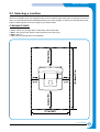
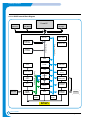
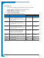
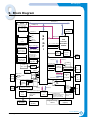
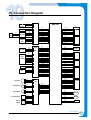
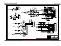
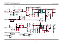
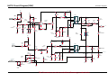
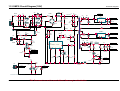
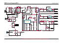
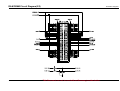
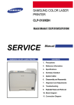
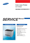
Block Diagram 9 9. Block Diagram DATA(0:31) ROM ADDR(2:23) Prog. ROM 2M*2 Font ROM 1M*2 Voltage (Built in Board) Regulator ROMCS(0:1) nRD nWR Blank DIMM nReset for ROMCS(2:3) Options Memory Data Bus SDRAM DRAMD(0:31) SDRAM 16MB*2 Memory Address Bus Working Mem. (Built in Board) S P G P i ADDR(0:31) CPU PowerPC TS*, TT1,nTSBT, TSIZ(0:2) SPC603IFT nTA,RST*,INT*,nTS,nBG 266MHz SYSCLK X-Tal DRAMA(0:12) EMI Attenuator Process Clock DQM(0:3),BA(0:1) RAS,CAS,SCS(0:3) SDCLK(0:1),CKE UART Control Signals SDRAM DIMM Extension Mem. Voltage Max.128MB Regulator DATA(16:31) ADDR(2:6) X-Tal IOCS,nRD,nWR X-Tal EMI Attenuator nUSB_DREQ,nINT USB_RST Voltage Detecto r Supply USB2.0 D+ DVBUS Controller Serial EEPRO 5V 3.3V M Dout Din CS CLK DATA(16:31) Bus Control Signals Network OPTION I/F NPC Connector & wireless ACK*, BUSY, SELECT,ERROR,FAULT* 5 PC 1284 D+ 4 PD(0:7) Buffer Video LVDS 8 D- 1284 Impedance Stepper Motor Control Signals Dri ver BLDC Motor Control Signals LSU Engine I/O Control Motor nHs ync . nLReady nPmotor Clock ADDR(2:9) Data(0:7) Matching Circuits Stepper USB 2.0 ADDR(2:18) 24VS SELIN* STROBE* AUTOFD* INI* PC RESET* Micro SW Power USB C lock nUSB_DACK Video Clock LCD Panel ASIC Clucth(MP,Regi) Sensor(MP,Paper,Duplex) PWM(THV,MHV,DEV) Engine Control Devices Duplex Motor Main Motor Engine Drivin g (Stepper) (BLDC) Citcuit SCF Control Signals SCF (Option) Service Manual Samsung Electronics 9-1 Block Diagram 9-2 Service Manual Samsung Electronics Connection Diagram 10 10. Connection Diagram 1 2 3 3.3V BIN_FULL GND 1 2 THERM1 THERM2 1 2 3 4 GND P_REGI P_EMPTY 3.3V Paper Size PBA 1 2 3 4 P_SIZE1 P_SIZE2 P_SIZE3 GND Exit_Sensor 1 2 3 3.3V SIGNAL GND Outbin_Full Sensor Thermistor 1 Regi 2 Sensor 3 VCC SIGNAL GND Sensor PBA Toner Cartridge 1 2 3 4 5 6 7 8 Lamp 1 2 Inlet 1 2 3 Tray2 Clutch Joint PBA SMPS / HVPS MHV NC NC OPC_GND NC SUPPLY NC DEV 24V NC GND 1 2 3 24V 1 2 Tray2 Solenoide GND 24V Tray1 Solenoide Tray1 Empty Sensor Tray2 Out (PBA In) 1 2 GND 5V SIGNAL GND 1 2 3 NC GND CST_OUT 1 2 3 Main PBA 12 11 10 9 8 7 6 5 4 3 2 1 GND CART_CLK CART_DATA 3.3V P_EMPTY P_REGI THERM1 THERM2 P_SIZE1 P_SIZE2 P_SIZE3 OUTBIN_FULL 1 2 3 4 5 6 7 8 9 10 11 12 2 1 4 3 6 5 8 7 10 9 12 11 14 13 16 15 18 17 20 19 22 21 24 23 NC 24V DEV_PWM 24V MHV_PWM 24V GND GND MHV_READ GND THV_READ 3.3V THV_EN 3.3V THV_PWM GND 24VS GND VCC VCC NC P_EXIT P_DULPEX FUSER 1 2 3 4 5 6 7 8 9 10 11 12 13 14 15 16 17 18 19 20 21 22 23 24 Connector PBA 8 7 6 5 4 3 2 1 24VS TRAY2 SOL TRAY1 SOL TRAY2 CLUT TRAY1 EMPTY 3.3V TRAY2 OUT GND 1 2 3 4 5 6 7 8 1 2 3 4 5 6 7 8 9 10 11 12 LSUCLK /LREADY /LASER MOT GND 24V 1 2 3 4 5 3.3V VDOVDO+ /LD_ON GND 5VS /HSYNC 7 6 5 4 3 2 1 LSU P_Motor LD_PBA 1 2 24V 24VS 1 2 3 4 5 6 VCC 3.3V PANEL_TX PANEL_RX PANEL_RST GND 6 5 4 3 2 1 1 2 3 4 PA_1 PA_2 PB_1 PB_2 4 3 2 1 1 2 3 4 5 6 7 8 9 24VS 24VS GND GND GND VCC /START_STOP MOT_RDY MOT_CLK 9 8 7 6 5 4 3 2 1 1 2 3 4 5 6 7 8 3.3V SCF_STS SCF_GND SCF_CLK SCF_RDY 24V GND GND 8 7 6 5 4 3 2 1 1 2 3 24V NC GND Main_Fan 1 2 24V GND Sub_Fan 1 2 VCC GND PTL Cover Open Switch Panel Sub_Motor Main_Motor SCF_ Controller Service Manual Samsung Electronics 10-1 Connection Diagram 10-2 Service Manual Samsung Electronics Main Circuit Diagram(1/9) Schematic Diagrams This Document can not be used without Samsung’s authorization. 11-1 Main Circuit Diagram(2/9) 11-2 This Document can not be used without Samsung’s authorization. Schematic Diagrams Main Circuit Diagram(3/9) Schematic Diagrams This Document can not be used without Samsung’s authorization. 11-3 Main Circuit Diagram(4/9) 11-4 This Document can not be used without Samsung’s authorization. Schematic Diagrams Main Circuit Diagram(5/9) Schematic Diagrams This Document can not be used without Samsung’s authorization. 11-5 Main Circuit Diagram(6/9) 11-6 This Document can not be used without Samsung’s authorization. Schematic Diagrams Main Circuit Diagram(7/90) Schematic Diagrams This Document can not be used without Samsung’s authorization. 11-7 Main Circuit Diagram(8/9) 11-8 This Document can not be used without Samsung’s authorization. Schematic Diagrams Main Circuit Diagram(9/9) Schematic Diagrams This Document can not be used without Samsung’s authorization. 11-9 11-2 HVPS Circuit Diagram(1/2) Schematic Diagrams 24V1 5V1 C404 472 ZD401 2.7V R403 1.5M 5V1 MHV-sen MHV PWM CN1-#6 MHV 13 5 6 R401 47K + - D402 1N4148 C403 331 >> MHV 5 6 1 7 R414 1/2W60MF C409 3KV471 Q404 C2316 C458 MY2A473 Q403 C945C-Y ZD402 2.7VB D403 D1NL20U R413 30KF IC104/D + 12 - R460 RD1/8W1.5K MHV READ CN1-#10 13 C457 CE-103 KA324 C456 MY2A473 ZD404 3.3B C460 47uF D455 1N4148 14 MHV_READ D456 1N4148 ZD501 2.7V C459 1KV221 MHV 20K MHV_READ 50K R458 RS1/8W30KF >> OPC ZD403 100V R417 100J R412 1/4W5 R416 1/2W100M >> MHV-sen 5V1 R461 RD1/8W2.2KJ R415 MF1/2W100K 5V1 R408 10K C402 102 R450 1/2W560K 2 C407 103 R404 10K R402 22K C401 473 C405 104 Q401 A708-Y 7 D404 4KV 4 R411 470 >> 12 IC103/F 7407 T401 R409 5.6K D401 1N4148 R400 5.6K C406 CE-103 R410 100K C410 CE-104 24V1 5V1 C504 472 5V1 R509 5.6K D501 1N4148 2 R501 47K BIAS PWM CN1-#4 3 + 2 - 4 BIAS >> R502 22K C502 102 D502 1N4148 R504 10K C503 681 HVPS_+5V R103 1W1KJ 11-10 Q101 C1008 IN OUT C101 35V47uF R102 1KJ 6 1 7 5V1 D503 D1NL20U C550 2KV101 5V1 C102 35V47uF This Document can not be used without Samsung’s authorization. R515 MF1/2W50K >> SUPPLY R514 1/2W10MF ZD503 180V C509 3KV471 >> BIAS-sen R513 30KF R518 100J C508 47uF IC101 KA7805 GND 3.3V R512 1/4W10 5 24V1 R104 100J R101 3KJ ZD502 2.7VB D504 4KV 2 Q504 C2316 Q503 C945C-Y Q102 B1151-Y C505 104 C507 MY-2A103 R508 10K R550 1/2W1.8M 4 R511 470 Q501 A708-Y 1 C501 473 24VS T501 8 R500 5.6K 1 BIAS-sen C506 CE-103 R510 100K R503 330KF DEV 50K >> R517 MF1/2W50K R516 1/2W15MF DEV HVPS Circuit Diagram(220V) Schematic Diagrams 5V1 24V1 5V1 C207 CE-103 R209 100K T201 R203 100 4 Q201 A708-Y THV THV PWM CN1-#16 R202 430 D201 1N4148 >> 3 + 2 47K - C202 102 C203 681 R206 16.2KF 6 1 7 D204 6KV R207 330KF C205 MY-2A471 D203 D1NL20U D202 D1NL20U C213 2KV221 R211 1/4W4.7J R302 RD1/8W470K R300 100 R212 RD1/2W100K VA201 7D431K R213 BLR1/2W30M VA202 7D431K 24V1 C302 CE-103 T301 Q300 A708-Y THV R301 430 Q301 945C-Y R310 1K R303 RD1/8W470 4 C301 MY2A104J C306 MY2A473J INDEX 50K +5V1 RS1/8W330KF THV READ CN1-#12 7 + 5 - 6 6 1 7 R304 1/4W4.7 R305 MGR1/2W50M >> THV-sen D303 1N4148 D301 D1NL20U ZD301 2.7VB D305 1N4148 5 C304 3KV151 R306 RS1/8W100KF Q302 C2383 R307 D302 4KV 2 C303 103 R311 2.2k R308 1.5K C307 MY2A473J C210 C208 MY-2A681 5V1 THV_READ C211 6KV221 D206 6KV 6KV221 Q203 C2383 ZD201 2.7VB THV -EA CN1-#14 D205 6KV >> THV THV 50K C201 MY2A473 5 R208 10K 4 R201 R-/6W2KJ R205 22K C209 6KV221 2 Q202 945C-Y 1 R204 C206 MY-2A104 IC105/A KA358 11 THV-sen R210 5.6KJ C204 CE-103 D304 1N4148 C305 CE-104 IC105/B ZD302 3.3B This Document can not be used without Samsung’s authorization. 11-11 11-3 SMPS Circuit Diagram(110V) Schematic Diagrams AR2 F1 125V8A C1 474 TNR1 TH2 F2 125V5A GAP1 C7 10D-15 R4 3W47KJ 630V103K TH1 IC4_IN C3 LF1 CN1 474 C14 LF2 C6 200V560uF 2 O +3.3V1.5A CN3-11,13 D1 C16 C15 R3 1W47KJ AR1 10D221K I 4 C35 68pF D5SBA60 BD1 1 D4 G 3 C4 IC4 KA378R33 15 2 R2 1W47KJ R25 C 4 R1 C25 T1/A C17 50V104J GND 10,11,12 CN3-15,17 GAP2 B2 HVPS__+5V 14 R10 1/4W22J C13 35V33uF D7 D3 8 R30 C30 630V333 FUSIBLE 1W47J IC3 KA278R05 L2 AY-70H 13 D2 1N4148 R17 15KJ C24 GND CN3-15,17 10,11,12 IC1 C26 R26 8 IC-ICE2XS01 IC6 TLP3061F C21 R13 120J CN3-1,3,5 200V20A D5 C19 10,11,12 1 2 3 C20 C10 683J C8 222J R21 47KF R7 1W0.25J IC4_IN 3.3V IC2 KA431Z R39 15KJ R38 100J 24PIN 53014-0310 R20,24,27,14 2W2KJ*4 PC1 CN3-10 C5 683J EXIT SENSOR C22 50V104J R11 22.6KF PC1 FUSER_ON R34 1KJ R8 2KJ 4 CN3-9 +24V3.0A 4 FEED BACK 3 +24VS2 I-SENSOR SOFT START 2 N.C 1 7 GND R33 RD1/4W1.5KJ Q2 C1008-Y L1 9 N.C 50V104J CN4 B3,B4 FUSIBLE 1W180J +5V0.7A CN3-11,13 R15 10KJ 5 6 C31 R5 82J GATE VCC R32 OP1 100J R40 C9 C34 472MAA B1 24Pin DUPLEX SENSOR C33 50V104J NO MARKING RESISTOR 1/8W-J(5%) 11-12 2 O C23 IC5 R31 1W100J D6 60V3A 7 4C CN2 Q1 11N60 I 3G R6 4.7J 1 This Document can not be used without Samsung’s authorization. R12 2.49KF GND CN3-7,9 SMPS Circuit Diagram(220V) Schematic Diagrams AR2 F1 250V5A C1 474 TNR1 TH2 F2 250V3.15A GAP1 C7 10D-13 R4 3W47KJ 630V103K TH1 IC4_IN LF1 CN1 474 C14 LF2 C6 400V270uF I 2 O +3.3V1.5A CN3-11,13 4 D1 C16 C15 R3 1W120KJ AR1 10D561K 1 D4 C35 68pF D5SBA60 BD1 IC4 KA378R33 G 3 C4 R25 15 2 R2 1W120KJ C 4 R1 C25 T1/A C3 C17 50V104J GND 10,11,12 CN3-15,17 GAP2 B2 HVPS__+5V 14 R10 1/4W22J C13 35V33uF D7 D3 8 R30 C30 630V333 FUSIBLE 1W47J IC3 KA278R05 L2 AY-70H 13 D2 1N4148 R17 15KJ 2 O GATE 5 VCC 6 R32 C31 R5 82J GND CN3-15,17 10,11,12 R15 10KJ IC1 C26 R26 8 IC-ICE2XS01 IC6 TLP3061F +24V3.0A C19 R20,24,27,14 2W2KJ*4 1 GND CN3-7,9 2 3 C10 683J C8 222J R21 47KF R7 1W0.45J IC4_IN IC2 KA431Z R39 15KJ R38 100J 24PIN R11 22.6KF C20 3.3V EXIT SENSOR C22 50V104J PC1 CN3-10 C5 683J 53014-0310 R8 2KJ PC1 FUSER_ON R34 1KJ CN3-1,3,5 200V20A D5 10,11,12 4 CN3-9 Q2 C1008-Y C21 4 R13 330J FEED BACK 3 +24VS2 I-SENSOR SOFT START 2 N.C 1 GND 7 R33 RD1/4W1.5KJ L1 9 N.C 50V104J CN4 B3,B4 FUSIBLE 1W180J +5V0.7A CN3-11,13 C24 C23 IC5 R31 1W22J D6 60V3A 7 4C CN2 Q1 08N80 I 3G R6 4.7J 1 OP1 100J R40 C9 C34 472MAA R12 2.49KF B1 24Pin DUPLEX SENSOR C33 50V104J NO MARKING RESISTOR 1/8W-J(5%) This Document can not be used without Samsung’s authorization. 11-13 SMPS Circuit Diagram(220V for China) AR2 F1 250V5A C1 474 TNR1 Schematic Diagrams TH2 F2 250V3.15A GAP1 C7 10D-13 R4 3W47KJ 630V103K TH1 IC4_IN LF1 474 C14 LF2 C4 C6 450V270uF I 2 O +3.3V1.5A CN3-11,13 4 D1 C16 C15 R3 1W120KJ AR1 10D561K 1 D4 C35 68pF D5SBA60 BD1 IC4 KA378R33 G 3 R1 R25 15 2 R2 1W120KJ C 4 CN1 C25 T1/A C3 C17 50V104J GND 10,11,12 CN3-15,17 GAP2 B2 HVPS__+5V 14 R10 1/4W22J C13 35V33uF D7 D3 8 R30 C30 630V333 FUSIBLE 1W47J IC3 KA278R05 L2 AY-70H 13 D2 1N4148 R17 15KJ C24 GND CN3-15,17 10,11,12 IC1 C26 R26 8 IC-ICE2XS01 IC6 TLP3061F +24V3.0A CN3-1,3,5 200V20A D5 C19 10,11,12 4 2 3 C20 C10 683J C8 222J R21 47KF R7 1W0.45J IC4_IN 3.3V IC2 KA431Z R39 15KJ R38 100J 24PIN EXIT SENSOR R20,24,27,14 2W2KJ*4 PC1 CN3-10 C5 683J 53014-0310 C22 50V104J R11 22.6KF PC1 FUSER_ON R34 1KJ R8 2KJ 1 CN3-9 Q2 C1008-Y C21 4 R13 330J FEED BACK 3 +24VS2 I-SENSOR SOFT START 2 N.C 1 GND 7 R33 RD1/4W1.5KJ L1 9 N.C 50V104J CN4 B3,B4 FUSIBLE 1W180J +5V0.7A CN3-11,13 R15 10KJ 5 C31 R5 82J GATE VCC 6 R32 OP1 100J R40 C9 C34 472MAA B1 24Pin DUPLEX SENSOR C33 50V104J NO MARKING RESISTOR 1/8W-J(5%) 11-14 2 O C23 IC5 R31 1W22J D6 60V3A 7 G 3 CN2 Q1 08N80 I C 4 R6 4.7J 1 This Document can not be used without Samsung’s authorization. R12 2.49KF GND CN3-7,9 11-3 Network Card Circuit Diagram(1/5) This Document can not be used without Samsung’s authorization. Schematic Diagrams 11-15 Network Card Circuit Diagram(2/5) 11-16 This Document can not be used without Samsung’s authorization. Schematic Diagrams Network Card Circuit Diagram(3/5) Schematic Diagrams ML-2152W ONLY Addr17 Addr18 Addr19 . Addr20 Addr21 Addr22 0 PLL ON 1 PLL OFF 0 DEBUG 1 0 . NORMAL .8BIT 1 . 16BIT . 0 XP I/F 1 IEEE1284 0 1 USB Disable USB Enable 0 EDO DRAM 1 SDRAM This Document can not be used without Samsung’s authorization. PLL ON NORMAL . 16BIT XP I/F USB Enable SDRAM 11-17 Network Card Circuit Diagram(4/5) 11-18 This Document can not be used without Samsung’s authorization. Schematic Diagrams Network Card Circuit Diagram(5/5) This Document can not be used without Samsung’s authorization. Schematic Diagrams 11-19 11-4 SCF PBA Circuit Diagram(1/2) 11-20 This Document can not be used without Samsung’s authorization. Schematic Diagrams SCF PBA Circuit Diagram(2/2) Schematic Diagrams This Document can not be used without Samsung’s authorization. 11-21 11-5 RAM DIMM Circuit Diagram(1/2) 11-22 This Document can not be used without Samsung’s authorization. Schematic Diagrams RAM DIMM Circuit Diagram(2/2) Schematic Diagrams This Document can not be used without Samsung’s authorization. 11-23 11-6 Panel PBA Circuit Diagram 11-24 This Document can not be used without Samsung’s authorization. Schematic Diagrams 11-7 PS3 ROM Circuit Diagram Schematic Diagrams This Document can not be used without Samsung’s authorization. 11-25 11-8 Connector PBA Circuit Diagram 11-9 Cover Open Sensor Circuit Diagram 11-26 This Document can not be used without Samsung’s authorization. Schematic Diagrams 11-10 Enpty Sensor Circuit Diagram Schematic Diagrams 11-11 Exit Sensor Circuit Diagram This Document can not be used without Samsung’s authorization. 11-27 11-12 OPC PBA Circuit Diagram 11-13 Toner PBA Circuit Diagram 11-28 This Document can not be used without Samsung’s authorization. Schematic Diagrams 11-14 Zener PBA Circuit Diagram Schematic Diagrams This Document can not be used without Samsung’s authorization. 11-29