1
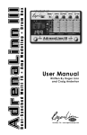
Version 3.10
Software Upgrade
For the Akai MPC60 and MPC60-II
Installation Instructions
Written by Roger Linn
Revision date: January 8, 2004
Copyright 1996-2001 Roger Linn Design
1
Before you begin...
The installation process you are about to do requires only that you open up your MPC60 and exchange
four chips in removable sockets for four new chips. Most of our customers do this installation themselves.
However, if you have never done a simple installation such as this, you may find it difficult. Before you
begin, please read over these installation instructions carefully and decide whether you are comfortable
doing this installation. If you don’t feel comfortable doing it, please ask someone who is more familiar with
simple electronic installations to do it for you. Please note that in the event of a problem resulting from
incorrect installation, we will try to help you but Roger Linn Design is not liable for any damage to your
MPC60 or MPC60-II as a result of problems resulting from your installation. If you do decide to do it
yourself, please follow the instructions slowly and carefully. Thanks.
Before starting, locate the 4 ROM integrated circuit chips that contain the new operating software. In
addition, you will need the following tools:
• A medium Phillips (cross head) screwdriver
• A small flat blade screwdriver (to remove chips from sockets)
• A drumstick or something like a drumstick (to prop the lid of the MPC60 open)
Before doing anything, unplug the power. (Very important!)
Open the MPC60
Opening the chassis is different for the original MPC60 than for the MPC60-II. Instructions for both are
shown below.
If you have the original MPC60
• Remove 2 screws on each side as indicated in the diagram by the arrows.
right side
left side
right side
• The top is hinged at the back. Lift the lid from the front edge, lifting from under the padded arm rest.
Prop up the lid, using something like a drumstick.
If you have the MPC60-II
• As shown by the arrows in the diagram below, remove 3 screws on the right side, 3 screws on the left
side, 5 screws on the rear panel, and 4 screws on the front edge of the bottom panel.
2
left side
right side
rear panel
right side
front edge of bottom panel
• Without the screws, the lid is not connected to the bottom of the chassis, but many wires connect
between the two sections. Carefully lift the front of the top section and place the back of the top section
under the back of the bottom section as shown. Prop up the lid, using something like a drumstick.
Install the new ROM chips
Now that the chassis is open, the remaining steps are identical for the MPC60 and MPC60-II. However,
the instructions are different if you have the Marion Systems MPC-SCSI upgrade installed. Instructions for
both are shown below.
power supply
upper
P.C. board
If your unit does not have the MPC-SCSI upgrade
installed
The diagram to the right shows how the inside of both
the MPC60 and MPC60-II appears. The following
instructions refer to that diagram.
• Locate the 4 existing ROM chips in their sockets.
Before you remove them, write down which chip goes
in which socket in case you want to reinstall the old
chips later. To remove the old chips, carefully insert a
small blade screwdriver between each chip and its
socket on one end and very gently twist the
screwdriver to pry the chip up a small amount. (Don’t
insert the screwdriver between the socket and the P.C.
board as this will remove the socket!) Then, do the
same thing on the other end of the chip and again pry it
up a small amount. Do this a little bit on each end a
few times until the chip is removed from the socket. Repeat
this process for the 3 remaining chips.
• Find the 4 new ROM chips supplied in this kit and remove
them from the shipping tube. First, very carefully bend the
pins on each chip so that the 2 rows of pins are parallel to
each other. (See diagram below.) This can be done by
3
upper
P.C. board
lower
P.C. board
4 ROM
chips
disk
drive
front edge
Inside of chassis viewed from above
Angle of pins
as shipped
Angle of pins
after bending
pressing one edge of the chip, then the other, against a flat surface
such as a table.
• Notice that each chip has 4 numbers on the right side of its sticker.
(See diagram at right.) An asterisk (*) next to the number shows
which of the 4 sockets the chip should be inserted into. Gently insert
the 4 chips into the 4 sockets, orienting them as shown and being
very careful not to bend any of the pins while inserting. After you
have installed all 4 chips, visually inspect them to see if any pins are
not correctly inserted into the socket.
• That’s all. Now, close the lid. Don’t put the screws back in yet—
we’re going to test it first. Skip down to the section “Test the
installation”.
MPC60
*1
v3.00
2
11/3/95
3
©RLD 1995 4
MPC60
1
v3.00
*2
11/3/95
3
©RLD 1995 4
MPC60
1
v3.00
2
11/3/95
*3
©RLD 1995 4
MPC60
1
v3.00
2
11/3/95
3
©RLD 1995 *4
The asterisk
(*) on the
right side of
each label
shows the
correct
socket
position for
each chip.
Position
the chips
so that the
notch at
the end is
pointing to
the right.
Correct position of 4 ROM chips
chips
If your unit does have the MPC-SCSI upgrade installed
The diagram on the right shows a top view of the center circuit board of the MPC60 or MPC60-II with the
MPC-SCSI board installed. (The appearance is the same for the MPC60 and MPC60-II.) This circuit board
contains the 4 ROM operating software chips to be changed. The following instructions refer to this
diagram.
• On the Marion Systems MPC-SCSI board, disconnect wire “A” from connector “B”. Then remove 2
screws “C” and set them aside.
• Slowly and carefully fold the MPC-SCSI board back over the
circuit board immediately behind it and hold it back using
something like a book.
• With the MPC-SCSI board folded back out of the way, locate the
4 existing ROM chips “D” in their sockets. Before you remove
them, write down which chip goes into which socket in case you
want to reinstall the old chips later. To remove the old chips,
carefully insert a small blade screwdriver between one of the
chips and its socket on one end and very gently twist the
screwdriver to pry the chip up a small amount. (Don’t insert the
screwdriver between the socket and the P.C. board as this will
remove the socket!) Then, do the same thing on the other end of
the chip and again pry it up a small amount. Do this a little bit on
each end a few times until the chip is removed from the socket.
Repeat this process for the 3 remaining chips.
upper P.C.
board
• Find the 4 new ROM chips supplied in this kit and remove them
from the shipping tube. First, very carefully bend the pins on each
chip so that the 2 rows of pins are parallel to each other. (See
diagram on previous page.) This can be done by pressing one
side of the chip, then the other, against a flat surface such as a
table.
• Notice that each chip has 4 numbers on the right side of its
sticker. (See diagram “Correct position of 4 ROM chips” above.)
An asterisk (*) next to the number shows which of the 4 sockets
4
A
SCSI INTERFACE
FOR AKAI MPC-60
MARION SYSTEMS
CORPORATION
C
D
B
the chip should be inserted into. Gently insert the 4 chips into the 4 sockets, orienting them as shown and
being very careful not to bend any of the pins while inserting. After you have installed all 4 chips, visually
inspect them to see if any pins are not correctly inserted into the socket.
• Fold the MPC-SCSI board back forward into its original position. Replace screws “C”. Reconnect wire “A”
to connector “B”.
• That’s it. Now close the lid. (On the MPC60-II, carefully place the top section back down on the bottom
section.). Don’t put the chassis screws back in yet— we’re going to test it first.
Test the installation
• Connect the power cord and turn the power switch on. The screen should quickly display some text. If
not, immediately turn the power off, disconnect the power cable and check all previous steps. Especially
check the installation of the new ROM chips, checking for bent pins, direction of notch at end of chip, and
chips not fully inserted into sockets. Also, check to see that all connectors are connected correctly.
• If text appeared on the screen when power was turned on, indicating correct operation, then proceed
with reassembling the unit. To do this, first turn power off and disconnect the power cord, then install all
screws in the same places as during disassembly.
• To get started quickly using your new Version 3.10 software, read the section of the V3.0 Operators
Manual entitled “What are the new features in Version 3”. To learn about the newer features of version
3.10 (added after the release of version 3.0), read the V3.10 Manual Addendum.
Roger Linn Design
1563 Solano Ave., #472, Berkeley, CA 94707
(510) 898-4878
[email protected]
www.rogerlinndesign.com
5