1
3
Software version 2.0
Operator's Manual
By Roger Linn
Copyright 1987, 1988, 1989 Akai Electric Co., LTD.
Document revision date: April 20, 1989
4
READ THIS BEFORE YOU START!
Power requirements
Power requirements for electrical equipment differ from area to area. The
operating voltage of this machine is preset at the factory according to its
intended destination. However, some models are equipped with a voltage
selector. If your machine is so equipped, before connecting, check to see
that the VOLTAGE SELECTOR on the rear panel is set to the voltage
for your area. If not, please set it correctly before plugging in the
power cord:
220V, 50 Hz for Europe except UK.
240V, 50 Hz for UK and Australia.
120V, 60 Hz for U.S.A. and Canada.
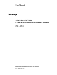
If the VOLTAGE SELECTOR on your machine looks like this: If the
VOLTAGE SELECTOR on your MPC60 looks like the diagram on
the right, please disconnect the power cord, then set the switch to the
correct voltage for your area, using a flat screwdriver.
What you should know to protect yourself and the Akai
MPC60:
Watch out! You might get an electric shock.
• Never touch the power plug with wet hands.
• Always pull out the power plug by the plug and never the cord.
• Only let a qualified professional repair or reassemble the Akai MPC60. An
unauthorized person might touch the internal parts and receive a serious
electric shock.
• Never allow a child to put anything, especially metal, into the Akai
MPC60.
Let's protect the Akai MPC60 too.
• Use only a household AC power source. Never use a DC power
source.
• If water is spilled on the Akai MPC60, disconnect the power and call
your dealer.
• Make sure that the Akai MPC60 is well ventilated and away from direct
sunlight.
• To avoid damage to the internal circuits and the external surface, keep
away from heat (stoves, etc.)
5
• Avoid using spray type insecticide near the Akai MPC60. It can damage
the finish and might ignite suddenly.
• To avoid damaging the finish, never use denaturated alcohol, paint
thinner or other similar chemicals to clean the Akai MPC60.
• Place the Akai MPC60 on a flat and solid surface.
WARNING!
Warning - This equipment generates, uses, and can radiate radio frequency
energy and if not installed and used in accordance with the instructions
manual, may cause interference to radio communications. It has been tested
and found to comply with the limits for a Class A computing device pursuant
to Subpart J or Part 15 of FCC Rules, which are designed to provide
reasonable protection against such interference when operated in a
commercial environment. Operation of this equipment in a residential area is
likely to cause interference in which case the user at his own expense will be
required to take whatever measures may be required to correct the
interference.
"This digital apparatus does not exceed the Class A limits for radio noise
emissions from digital apparatus set out in the Radio Interference
Regulations of the Canadian Department of Communications"
For customers in the UK
IMPORTANT FOR YOUR SAFETY - TWO CORE FLEX
The wires in the mains lead of your
machine are coloured in accordance
with the following code: Blue: Neutral
Brown: Live As the colours of the wires
in the mains lead of this apparatus may
not correspond with the coloured
markings indentifying the terminals in
your plug, proceed as follows: The wire
which is coloured blue must be
connected to the terminal which is
marked with the letter N or coloured
black.
The wire which is coloured brown must be connected to the terminal which
is marked with the letter L or coloured red.
• When wiring a plug, do not connect any wire to the larger pin marked
either by "E" or by this symbol:
Ensure that all terminals are securely tightened and that no loose strands
of wire exist.
6
Table of contents
SECTION 1: INTRODUCTION
1.1 Welcome!
1.2 How to use this manual
SECTION 2: THE BASICS
2.1 Overview
2.2 Hooking up your system and turning the MPC60 on
2.3 The CURSOR keys
2.4 The NUMERIC KEYPAD, DATA CONTROL and +/- keys
2.5 The SOFT KEYS (1-4)
2.6 The HELP key
2.7 The Dynamic drum pads
2.7.1 The FULL LEVEL and 16 LEVELS keys
2.7.2 The BANK 2 key
2.7.3 The HIHAT DECAY slider and the AFTER key
2.8 The DRUM MIX key - adjusting the stereo drum mixer
2.9 Playing the preset sequences
2.9.1 Changing sequences while playing
2.10 Adjusting the playing tempo
2.11 The MAIN SCREEN key - how to exit any function
2.12 The RESET TO DEFAULTS function
SECTION 3: RECORDING SEQUENCES
3.1 Overview
3.2 How sequences, tracks and channels are organized
3.3 The PLAY/RECORD screen - the main operating mode of the MPC60
3.4 How to assign "drums" and "non-drums" tracks
3.5 The PLAY/RECORD keys
3.6 An example of recording a drum sequence
3.7 An example of recording a sequence with both drums and keyboard parts
3.8 The TIMING CORRECT key
3.8.1 Correcting timing errors
3.8.2 The SHUFFLE feature
3.8.3 The SHIFT TIMING feature
3.8.4 The NOTE REPEAT feature
3.9 Tempo
3.9.1 The tempo screen
3.9.2 Mid-sequence tempo changes
3.9.3 The TAP TEMPO key
3.9.4 Speed limitations at fast tempos
3.10 The WAIT FOR KEY key
3.11 The AUTO PUNCH key
3.12 The 2ND SEQUENCE key
3.13 The COUNT IN key
7
3.14 The recording metronome
3.15 The two FOOT SWITCH inputs
3.16 The "Free sequence memory" display
3.17 Recording Midi system exclusive data
3.18 Transferring sequences to and from other sequencers
3.19 The "Analyzing sequence. Please wait..." message
SECTION 4: EDITING SEQUENCES
4.1 Overview
4.2 The ERASE key
4.2.1 Erasing notes while overdubbing ("Live erase" mode)
4.2.2 The Erase screen
4.3 The EDIT key
4.3.1 Viewing time signature changes
4.3.2 Creating a new sequence
4.3.3 Inserting blank bars into a sequence
4.3.4 Deleting bars from within a sequence
4.3.5 Copying a section, including all tracks, and inserting it elsewhere
4.3.6 Copying a single track to another area or merging it with other data
4.3.7 Copying an entire sequence to another sequence
4.3.8 Converting a song into a single long sequence
4.3.9 Shortening or lengthening a single bar
4.3.10 Changing the velocity or duration of a group of notes after recording
4.4 The STEP EDIT key
4.4.1 The step edit screen
4.4.2 Using step edit
4.4.3 Step recording
4.5 The EDIT LOOP key
4.5.1 Using EDIT LOOP as an "UNDO" function
4.6 The TRANSPOSE key
SECTION 5: SONG MODE
5.1 Overview
5.2 The song mode screen
5.3 An example of creating and playing a song
SECTION 6: SAMPLING AND EDITING DRUM SOUNDS - the SOUNDS key
6.1 Overview
6.2 Sampling a new sound
6.3 Editing an existing sound
6.4 Tuning the drums
6.5 The echo mixer
6.6 Assigning the 8 assignable mix outputs
6.7 Transferring sounds over midi: the Midi Sample Dump
6.8 Triggering a drum from an external signal - the audio trigger
6.9 Mixer modes, hihat decay thresholds, mufti-pitch mode
8
SECTION 7: SAVING TO AND LOADING FROM DISK
7.1 Overview
7.2 Saving a sequence
7.3 Saving all sequences and songs
7.4 Saving a drum sound
7.5 Saving all drum sounds
7.6 Saving a parameter file
7.7 Loading, erasing or renaming files
7.7.1 Files which automatically load on power-up
7.8 Formatting a disk
7.9 Copying an entire disk
7.10 "Attention" screens encountered during disk operations
7.11 The "Save warning" light above the DISK key
SECTION 8: SYNCING TO TAPE AND OTHER DEVICES
8.1 Overview
8.2 The Sync screen
8.3 Syncing to SMPTE
8.4 Syncing to FSK24
8.5 Syncing to 1/4 note clicks
8.6 Syncing to Midi Clock and Song Position Pointer
8.7 Syncing to Midi Time Code
SECTION 9: MIDI FUNCTIONS
9.1 Overview
9.2 The midi input filter, midi soft through, sustain pedal processing
9.3 External drum triggering, the midi "drums" channel
9.4 The ME-35T Audio/Midi Trigger interface screen
9.5 Midi implementation charts
SECTION 10: APPENDEX
10.1 Features
10.2 Technical specifications
10.3 What to do if your MPC60 isn’t working properly
SECTION 11: INDEX
Section 1:
Introduction
10
1.1 Welcome!
Thank you for purchasing the Akai MPC60. The Akai engineering team, my
engineering team and myself have all worked very hard to bring to you a
product which we truly believe answers the needs of today's professional
musician. I am sure you will find that the combination of innovative
features, high sound quality, ease of use and attention to detail will be very
useful in the process of composition, recording and performing. It has been
said that technology has always had a profound influence on art. If this is
true, I invite you all to take this piece of technology and use it to change the
direction of music for tomorrow. Now, let's begin...
P.S. I'd like to know if you use the MPC60 on any famous records. If so, I'd
appreciate it if you would write a brief letter to your local distributor and
they'll tell me. Thanks.
Section l: Introduction
1.2 How to use this manual
The MPC60 and this manual were designed for people who don't like
reading manuals and want to start working immediately.
The manual teaches the MPC60's operation in a logical, step-by-step
manner. The sections are presented in the order that most people want to
learn them. To start using your MPC60 as soon as possible, we recommend
that you first read (or skim) through sections 2 and 3, "The Basics" and
"Recording sequences", to get a general understanding of the MPC60. After
that, you will find that most other functions are very easy to figure out by
experimentation:
1. Press the key which you think would most likely contain the
function you are looking for. For example, to sample a new
sound, press the SOUNDS key.
2. Follow the instructions presented on screen. If you're
confused, press and hold the HELP key for further
explanation.
3. If you still can't figure it out, find the section in the manual
which explains that function, either by looking in the table of
contents or the index.
11
Section 2:
The Basics
14
2.1 Overview
This section is a simple introduction to operating the MPC60. In this section you will
learn to:
• Hook up the MPC60 to your system.
• Enter and change data and parameters using the CURSOR keys, the
NUMERIC KEYPAD, the DATA CONTROL, and the +/- keys
• Use the SOFT KEYS and the HELP key
• Play the drums and use the associated keys
• Adjust the stereo drum mixer
• Play the preset sequences
• Adjust the playing tempo and a
few other basic functions
Section 2: The Basics
2.2 Hooking up your system and turning it on:
To get started using the drum machine section:
1. Connect the power cord to an AC outlet. 2. Connect the STEREO
OUT LEFT and STEREO OUT RIGHT jacks to the inputs of an
amplifier or mixer.
Note: If you are only using the MPC60 as a drum machine right now, you
don't need any other connections. Skip down to the section "Turning the
MPC60 on".
To also use the sequencer section with a single integrated keyboard
synthesizer:
1. Connect the synthesizer's MIDI OUT to the MPC60's MIDI IN 1.
You may alternatively use MIDI IN 2. Both inputs merge together. 2.
Connect the MPC60's MIDI OUT 1 to the MIDI IN of the
synthesizer.
To use the sequencer section with a midi master keyboard and
separate multiple midi sound modules:
1. Connect the MIDI OUT of the midi keyboard to the MIDI IN 1 of the
MPC60. You may alternatively use MIDI IN 2. Both inputs merge
together. 2. Connect the MIDI OUT 1 of the MPC60 to the MIDI
INPUT of the first midi sound module. 3. Connect the MIDI THRU of
the first sound module to the MIDI INPUT of the second sound
module. 4. Connect the MIDI THRU of the 2nd sound module to the
MIDI INPUT of the third sound module, and continue this until all
sound modules are connected.
The above hookup only uses one of the four midi output jacks of the
MPC60. Later in the manual, you'll learn how to use all 4 of the midi output
jacks.
To use the sampling input, foot switches, sync input/output, echo
inputs/outputs, individual mix output 1 - 8, or the metronome output,
please read the corresponding sections of the manual.
Note: the RS-232C computer port currently has no function.
15
16
Turning the MPC60 on
1. Of the disks which are included with the MPC60, find the disk
"STUDIO SET and SYSTEM ALL" and place it into the disk drive. This
disk contains a general purpose set of drum sounds and a collection of
demonstration sequences.
Note: Every time you turn the MPC60's power on, you must re-load the
drum sounds (and sequences if desired) from disk. This is because ALL
SOUND AND SEQUENCE MEMORY IS LOST WHEN YOU TURN
THE POWER OFF. While it is true that most drum machines hold their
memory when power is removed, these are devices with very low memory
capacity. There are no samplers and no high capacity sequencers which
retain memory when power is removed for one reason: the cost of
low-power memory, which can be kept active by a battery, is much more
expensive than the type of memory commonly used. We at Akai believe the
customer would prefer to pay a substantially lower price for the minor
inconvenience of saving his work to disk before powering down. For this
reason, whenever you do any sampling or editing of sounds, or recording or
editing of sequences, you must always save the changes to disk, or the
changes will be lost!
2. Turn the power ON and wait for about 1 1/2 minutes for the MPC60 to
load the sounds and sequences into memory. While loading, the screen will
display the following message:
Note: If the version number is a lower number than 2.00, your MPC60 is
running an older software version. If so, you should update your MPC60
to version 2.00. To update your MPC60, contact your dealer or service
center and say "I want to have the latest software update installed in my
MPC60".
When finished loading (after about one minute), the following screen
should appear:
Section 2: The Basics
This is the PLAY/RECORD screen. It is the main operating mode of the
MPC60 and all playing and recording of sequences is done while this screen
is displayed. This screen will be discussed further in the section entitled
"Recording sequences'". If at any time while operating the MPC60 you are
confused and want to return to this mode, press the MAIN SCREEN key.
Note: There are three other disks included with the MPC60:
ROCK SET and SYSTEM ALL,
DRY SET and SYSTEM ALL, and
SYNTH SET and SYSTEM ALL.
These disks contain 3 additional sets of drum sounds, but contain the same
demonstration sequences. To hear the sounds on these disks, follow the
above instructions again, but use one of these disks instead. It is also
possible to load the files on these disks by using the DISK key, discussed
later in the section "Saving to and loading from disk".
17
18
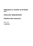
2.3 The CURSOR keys
While the PLAY/R,ECORD screen is showing, notice that a small
rectangular block is blinking near the upper left corner. This is called the
CURSOR. It is possible to move the cursor around the screen using the
four grey direction keys in the CURSOR section of the panel. Try doing
this, then return the cursor to the upper left corner where it was.
Notice that the cursor does not move from letter to letter, but rather
jumps across many letters at a time, landing only in certain locations,
usually to the right of a colon (":"). These areas are called DATA FIELDS
and each one controls a specific parameter. For example, the upper
leftmost data field is called SQNC, an abbreviation for "sequence". To the
right of this field is another field containing the name for the selected
sequence number, followed by the TMPO field, an abbreviation for
"tempo".
The PLAY/R,ECORD screen is one of many screens available on the
MPC60. Each of the panel keys presents at least one unique screen, and each
screen has its own unique data fields. Try pressing a few of the different keys
in the COMMANDS section of the panel such as DISK or TEMPO/SYNC.
When you're finished, press MAIN SCREEN to return to the
PLAY/RECORD screen.
Section 2: The Basics
2.4 The NUMERIC KEYPAD, DATA CONTROL and
+/- keys
The NUMERIC KEYPAD
To change the data in a field, move the cursor to it and type in the new
number using the numeric keypad, followed by ENTER. For example, to
change to sequence number 2:
1. Move the cursor to the SQNC field;
2. Type 2, followed by ENTER.
Notice that the sequence name (located immediately to the right of the
sequence number) now automatically changes, because it must now display
the name of sequence 2. Try changing the playing tempo in the same way
(move the cursor to the TMPO field).
Another use of the numeric keypad is to select from a list of options
presented on-screen. For example, pressing the DISK key causes the
following screen to be displayed:
If a screen like this is displayed, you are expected to select one of the
options by pressing a single number - it is not necessary to press ENTER
afterwards.
The DATA CONTROL
Another way of changing on-screen data is to use the DATA CONTROL.
While the cursor is in a data field, if the DATA CONTROL is rotated one
"step" to the right (as you turn the knob, you can "feel" the steps), the
on-screen number will increment by 1. If the DATA CONTROL is rotated
one step to the left, the on-screen number will decrement by 1.
Continuously turning the DATA CONTROL will repeatedly increment or
decrement the on-screen value. It is not necessary to press ENTER after
turning the data control.
There are certain data fields called "choice" fields. These fields do not
contain numeric data, but rather a specific number of preset
19
20
selections, but only one may be active at a time. In this case, the DATA
CONTROL is used to select from the available options. For example,
press the OTHER key and move the cursor to the RATE field, which is a
"choice" field. Now turn the DATA CONTROL and notice that with each
step of the control, a different preset option appears.
The + and - keys
Pressing the "+" key has the same effect as turning the DATA CONTROL
one step to the right. It either increments a number in a numeric field or
chooses a new option in a "choice" field.
Pressing the "-" key has the same effect as turning the DATA CONTROL
one step to the left. It either decrements a number in a numeric field or
chooses a new option in a "choice" field.
Section 2: The Basics
2.5 The SOFT KEYS (1 - 4)
In the upper right corner of the front panel are four buttons labeled SOFT
KEY 1, SOFT KEY 2, SOFT KEY 3 and SOFT KEY 4. The functions of
these buttons change from one screen to another and are always displayed
on the lowest line of the screen. For example, while the PLAY/RECORD
screen (accessed by pressing the MAIN SCREEN button) is showing. notice
the lowest line:
There are four titles enclosed in angle brackets ("<" and ">"). The titles are
<Trak=ON >, <Solo=OFF>, <Tmpo=SEQ> and <SortTrks>. These
four titles indicate the functions of the four soft keys, but only while this
screen is showing. Each of the many functions in the MPC60 displays a
unique screen of data, and the lowest line of each of these screens indicates
the function of the 4 soft keys while that screen is showing. Demonstrate
this by pressing the ERASE key, then the TIMING CORRECT key, then
MAIN SCREEN to return to the PLAY/RECORD screen. Some screens
have less than four active soft keys and some have none.
21
22
2.6 The HELP key
Whenever this key is pressed and held down, the contents of the screen
will be temporarily replaced with a paragraph of further explanation about
the function you are currently working with. To return to the previous
screen, release the HELP key. There is a different help screen for every
data field in every screen in the MPC60. To demonstrate this:
1. Press HELP, notice the screen, then release it;
2. Move the cursor to a different field;
3. Press HELP again, notice the different screen and release it.
Section 2: The Basics
2.7 The DYNAMIC DRUM PADS
The 16 drum pads are dynamic- the harder you strike them, the louder
the drum will sound.
2.7.1 The FULL LEVEL and 16 LEVELS keys
• The FULL LEVEL key: The FULL LEVEL key defeats the variable
dynamics of the drum pads, causing all drums to play at full dynamic level,
regardless of how hard or soft the pad is struck. However, this has no effect
on drums which are playing back from sequences. Press FULL LEVEL
once to turn this mode ON (the light will go on); press it again to turn it
OFF.
• The 16 LEVELS key:
This key has 2 functions, but only one may be in use at a time:
1. It may be used to play a single drum at 16 fixed dynamic levels,
using the 16 pads.
2. It may be used play a single drum at 16 fixed tunings, using
the 16 pads.
To select which of these 2 functions is currently in use, press the
SOUNDS key, then select option 8, "Mixer/hihat/other", and the
following screen will appear:
Now, move the cursor to the lowest field on the screen entitled
FUNCTION OF "16 LEVELS". This is a "choice" type field and has 2
options:
1. "16 VOLUMES": If this option is selected, the 16 LEVELS key
will cause a single sound to play from all 16 pads, but at 16 fixed
dynamic levels with the softest level on the lower leftmost pad
and the loudest level on the upper rightmost pad.
23
24
2. "16 TUNINGS": If this option is selected, the 16 LEVELS key
will cause a single sound to play from all 16 pads, but at 16 fixed
chromatic tunings, with the lowest tuning (-12 semitones) on the
lower leftmost pad, and the highest tuning (+3 semitones) on
the upper rightmost pad. If this mode is active and the pads are
played while recording, these tunings are remembered within the
sequence. After recording, the tuning of each note may be
adjusted in Step edit mode. This is explained further in the Step
edit section of this document.
Use the DATA CONTROL to select which function you wish to use.
Once set, your selection will be retained even after power is removed.
When you've finished, press the MAIN SCREEN key to return to the
PLAY/RECORD screen.
To use the 16 LEVELS key (regardless of the selected function):
1. Play the pad of the drum you want to use.
2. Press the 16 LEVELS key. The light will go on indicating the
feature is active. Now, the drum you played in step 1 will sound
when any of the pads are played, but at 16 fixed dynamic levels
(if "16 VOLUMES" is active) or at 16 fixed tunings (if "16
TUNINGS" is active).
3. To turn this feature off, press 16 LEVELS again and the light
will go off.
NOTE: The "16 TUNINGS" feature does not operate if the Hihat is
selected.
NOTE 2: The MPC60 performs its tuning all digitally without any
distortion, but substantial distortion may be heard if a drum is tuned which
was recorded at too high a record level. If you notice this distortion when
tuning your own sampled sounds, the only solution is to re-sample your
sound at a lower volume or to use a different sound which was not
over-recorded.
2.7.2 The BANK 2 key
The MPC60 may contain as many as 32 drums in memory at once, yet there
are only 16 front panel play pads. This button is used to select between
bank 1 (the first 16 drums: Hihat through Percussion 4) and bank 2 (the
second 16 drums: Drum01 through Drum16). Normally, bank 1 is active.
To activate bank 2, press BANK 2 and the light will go on to indicate bank
2 is active. To return to bank 1, press BANK 2 again and the light will go
out.
Section 2: The Basics
2.7.3 The HIHAT DECAY slider & the AFTER key
The slider controls the decay time of any notes played on the hihat pad,
similar to how the foot pedal on a real hihat controls its decay time. Also,
to add realism, one of three samples is played, depending on the position
of the slider:
1. If a hihat is played while the slider is in the lower 1/3 of its range, a
"closed hihat" sample is played; 2. If a hihat is played while the slider is
in the middle 1/3 of its range, a "medium open hihat' sample is played;
and 3. If the hihat is played while the slider is in the upper 1/3 of its
range, an "open hihat" sample is played.
It is possible to change the thresholds within the slider's travel at which
one hihat sample changes to another. To do this, read section 6.9 of the
manual entitled "Mixer modes, hihat decay thresholds, mufti-pitch mode".
The decay information is recorded into the sequence with each hihat note,
allowing every nuance of your hihat performance to be remembered.
Normally, the WHAT DECAY slider has no effect on hihat notes playing
back from sequences. However, if the AFTER key is pressed (and the light
goes on), the slider not only sets the decay for all new notes played, but also
overrides the decay of any existing hihats playing in sequences. Further, if in
RECORD or OVERDUB modes while the AFTER light is on, the current
setting of the decay slider will replace decay settings for any existing hihats
playing in the active track. To activate the AFTER mode, press AFTER (the
light will go on). To deactivate it, press AFTER again (the light will go off).
Note: The RECORD and OVERDUB modes will be described in the
next chapter, "Recording sequences".
25
26
2.8 The DRUM MIX key - adjusting the stereo drum
mix
To adjust the individual volume and pan settings for the stereo mix
outputs, press the DRUM MIX key and this screen will appear:
This is a graphic simulation of a 16 channel stereo mixer. For each channel,
there is a four letter abbreviation of a drum, a graphic representation of a
volume slider, and a graphic representation of a rotary pan control.
Depending on the setting of the BANK 2 switch, either the first 16 drums
(HIHT - PRC4) or the second 16 drums (DRO1 -DR16) will be displayed
for adjustment. You can press the BANK 2 switch before or during the
drum mix operation.
To adjust the volume of a particular drum: 1. Press the pad of the drum to
be adjusted - the small triangle will move to directly above the selected
drum; 2. Rotate the DATA CONTROL. As you turn it, the graphic
volume slider will move up or down, indicating that the volume of the
selected drum is being changed.
To adjust the pan position of a particular drum: 1. Press the pad of the drum
to be adjusted - the small triangle will move to directly above the selected
drum; 2. Press the CURSOR UP key - the small triangle will now point
upwards, toward the graphic pan knob; 3. Rotate the DATA CONTROL.
As you turn it, the graphic pan knob will move between one of 15 pan
positions, indicating that the pan of the selected drum is being changed.
Even though no soft key functions are displayed on the screen, there is one
active soft key: If SOFT KEY1 is pressed, the mixer changes to a mode in
which all drums are changed simultaneously, indicated by 16 cursor
triangles across the screen. This may be a global level or pan change. You
can change between level and pan with the UP an DOWN cursor keys. To
return to normal operation, press soft key 1 again.
NOTE: It is possible to select a special mode in which all mix changes
made in real time while recording will be replayed on playback, just like
an automated mixer. This is explained in section 6.9 of the manual
entitled "Mixer modes, hihat decay thresholds, multi-pitch mode".
Section 2: The Basics
2.9 Playing the preset sequences
To play some of the preset sequences included with the MPC60,
perform the following steps:
1. If you have not already done so, load the preset sounds and sequences
from disk as described in the section "Turning on the MPC60" or
Section 7 - "Saving to and loading from disk". Make sure the STEREO
MIX VOLUME control and your amplifier/mixer controls are set
properly.
2. Make sure the PLAY/R,ECORD screen is showing. If not, press
MAIN SCREEN;
3. Make sure the cursor is currently in the upper left field of the screen,
entitled SQNC, and that the number in this field is 1. If not, press 1,
then ENTER;
4. Press the PLAY START key - sequence number 1 should start
playing in a loop;
5. Press the STOP key - the sequence should stop playing;
6. Press 2, then ENTER - the name for sequence number 2 should
appear directly to the right of the sequence number;
7. Press the PLAY START key - sequence number 2 should start
playing in a loop;
8. Press the STOP key - the sequence should stop playing;
9. Turn the data wheel (very carefully) one step to the right, which should
cause the sequence number to increment to 3;
10. Press the PLAY START key - sequence number 3 should start
playing in a loop;
11. Press the STOP key - the sequence should stop playing.
2.9.1 How to change sequences while playing
It is also possible to change sequences while the MPC60 is playing. If
you do, the newly selected sequence will not start playing until the
current sequence has finished. When the new sequence number is
entered, the top line of the screen will display the message:
This indicates that the newly selected sequence (in this case,
sequence number 2) will start playing once the current sequence has
finished playing.
IMPORTANT!: This process will only operate while the top line of
the PLAY/RECORD screen displays the following words before the
new sequence is selected:
27
28
This indicates that the MPC60 is NOT enabled for recording. This process
will NOT operate if the MPC60 is enabled for recording, indicated by the
following top line of the PLAY/RECORD screen:
If these words are displayed, you must first disable recording by doing
the following:
1. Select a different sequence; then
2. Re-select the original sequence
This feature is very useful for creating the structure of a song in real time
while the MPC60 is playing. For example, while the sequence containing the
1st verse is playing, you could enter the sequence number contain the
chorus, which will starting playing once the verse sequence is finished.
Then, you might enter the sequence number containing the second verse,
which will start playing once the chorus sequence has finished. This process
may be continued infinitely.
NOTE: If you use the DATA CONTROL to select a new sequence while
playing, only the next higher or next lower sequence may be selected. If
you want to select a sequence which is greater than one higher or lower,
you must use the numeric keypad (remember to press ENTER after you
have entered the new sequence number).
NOTE 2: If you notice a timing irregularity at the point of transition from
one sequence into another, the problem may be due to the assignments of
the PROG field (in the PLAY/RECORD screen) for the sequence which
plays immediately after the timing irregularity. The PROG field is described
in section 3.3, "The PLAY/RECORD screen- the main operating mode of
the MPC60". If, while playing one sequence, you change to a sequence
containing these program assignments, the sequence's program assignments
are sent out at the moment that the sequence starts to play in the song. This
can present a problem because most synthesizers require a brief time delay
while changing programs, and this delay time will cause any notes existing at
the start of the new sequence to be delayed. This delay is brief in most
synthesizers, but is usually enough to cause a timing irregularity at the start
of the sequence. To avoid this problem, remove any assignments of the
PROG field for the sequence which you are changing to while playing (in the
above described manner). This problem does not apply to sequences
containing only drums tracks.
Section 2: The Basics
2.10 Adjusting the playing tempo
To adjust the playing tempo:
1. From the PLAY/RECORD screen, move the cursor to the TMPO
field - this is the tempo setting; 2. Change the tempo either by typing
in a new tempo number and pressing ENTER, or by turning the
DATA CONTROL;
There are other ways to adjust the tempo and many other tempo related
parameters. These will be discussed later in the section entitled
"RECORDING SEQUENCES".
29
30
2.11 The MAIN SCREEN key- how to exit any
function
Pressing the MAIN SCREEN key at almost any time will return you back to
the main PLAY/R,ECORD screen of the MPC60 without damaging any
data. Use this key as a "panic" button - if you find yourself in some function
you don't understand and want to get out.
Section 2: The Basics
2.12 The RESET TO DEFAULTS function
The contents of most of the data fields in each of the screens in the MPC60
are retained after the power is turned off and on again. Even though all
sounds and sequences are lost when power is removed, these settings are
retained by a special battery powered memory. Because of this, there is no
need to reset the MPC60's settings to your personal taste every time you
power on.
However, there are times when it is desirable to reset all of these settings
to their original factory-preset settings. There is a special function called
"Reset to defaults" which does exactly this. To perform a reset to defaults:
1. Press the OTHER key, and this screen will appear:
2. Press SOFT KEY 1, <Defaults>.
3. A second screen will appear, asking you if you are sure you want to reset
to defaults. Press SOFT KEY 1 again, <Reset to defaults>.
Now, all data fields will be reset to their factory-preset status.
NOTE: These settings which are retained with power removed may be
saved in a special file called a "Parameter file". See the DISK section of the
manual to learn more about this feature.
31
Section 3:
Recording
Sequences
34
3.1 Overview
This section describes functions which are used in the process of
recording sequences. In this section you will learn:
• How sequences, tracks and channels are organized
• How to use the PLAY/R.ECORD screen
• How to create both "drums" and "non-drums" tracks
• The keys in the PLAY/RECORD section of the panel
• How to record both a drum sequence and a multi-track keyboard
sequence
• How to use the TIMING CORRECT function
• The TEMPO function
• The WAIT FOR KEY and AUTO PUNCH keys
• How to use the recording metronome
• How to use the foot switches
• How to see how much memory is available for new sequence
recording
• How to record Midi system exclusive data
• How to transfer sequences to and from other sequencers
Section 3: Recording sequences
3.2 How sequences, tracks and channels are
organized
Sequences:
The MPC60 holds 99 sequences in memory at one time. A sequence can be
thought of as a segment of mufti-track tape of variable length. Depending
on the sequence contents, it could be a 2 bar repeating drum pattern, an
eight bar verse, or a 200 bar song with time signature and tempo changes.
Normally, only one sequence may play at one time, unless the 2ND
SEQUENCE feature is on, allowing two sequences to play simultaneously.
A sequence has a format consisting of time signature and number of bars.
If no format is assigned to a sequence, it is automatically given a time
signature of two bars of 4/4. However, this default setting may be
changed by pressing the EDIT key, then selecting option 2: CREATE
SEQUENCE.
Tracks:
Within each of the 99 sequences are 99 tracks, which contain the actual midi
events. These may be thought of as the tracks on a mufti-track tape recorder
- they each contain a specific instrument or piece of the total arrangement,
but all play simultaneously. For example, track 1 could be drums, track 2
percussion, track 3 bass guitar, track 4 piano, track 5 horns, track 6 more
horns, etc. Each track may be either a "drums" track or a "non-drums" track,
but not both. This is explained further in the section "How to assign drums
and non-drums tracks".
Channels:
In order for the sequences to play external synthesizers, it must send its
notes out through midi on one of the 64 midi output channels (16 channels
for each of the 4 midi output jacks). On the MPC60, each track may be
independently assigned to output its notes through any one of these 64
output midi channels. It is also possible to send the output of any track
through two midi output channels simultaneously.
Exactly how tracks and channels are assigned is explained later in the next
section entitled "The PLAY/RECORD screen - the main operating mode
of the MPC60".
35
36
3.3 The PLAY/RECORD screen - the main
operating mode of the MPC60
When the MPC60 is first powered on (with the STUDIO SET and
SYSTEM ALL disk in the drive), the following screen appears after the disk
has loaded:
Note: It is also possible to turn on the MPC60 without any disk in the
drive. In this case, no sounds or sequences will be loaded and the MPC60
may be used as a sequences only.
At this point, the device is in its standard operating mode, in which all
recording and playing of sequences is done. On this screen are presented
many data fields useful to the process of real-time recording. A detailed
description of each of the data fields and soft keys follows:
If this message appears, it means that the currently selected sequence is
ready to be recorded into. If the "(Record ready)" message is not displayed
and you want to record into the current sequence, press either the
RECORD or OVERDUB keys once, and the "(Record ready)" indicator
will be added to the title line, indicating that the current sequence is ready
to be recorded into. Remember that selecting a different sequence and then
reselecting the original one will remove the "(Record ready)" message.
• The SQNC field: This field displays the active sequence number, from 1 to
99. This is the sequence which will play when either the PLAY START or
PLAY keys is pressed. The MPC60 holds up to 99 sequences in memory at
one time.
Section 3: Recording sequences
The "sequence name" field: This is the 16 character name for the current
sequence. This field has no on-screen title, but is located directly to the right
of the SQNC field. To change the sequence name, move the cursor to this
field and turn the DATA CONTROL one step in either direction. This will
cause the keys which have the alphabetic letters printed next to them to
change to their alpha functions. To indicate that this alpha mode is active,
the cursor changes from the normal blinking block to a blinking underline.
Now change the name by typing in the letters printed above the keys. Use
the ERASE key as a space, and the TAP TEMPO key to change between
upper and lower case. The left and right cursor keys do not type letters, but
allow you to move backwards and forwards in the name. For punctuation,
position the cursor where you want the character to appear, and rotate the
DATA CONTROL knob until you see the character you want, then press
the right cursor key to move on to the next position. This process applies to
all names that you enter into the MPC60 (sequences, songs, sounds, etc.).
When finished, press ENTER and the cursor will return to a blinking block
at the beginning of the field, indicating that the alpha keys have returned to
their normal functions.
Note: If the DATA CONTROL is not turned while the cursor is in this
field, moving the cursor one position to the left or right will move to the
previous or next data field - not the adjacent character position within
the sequence name.
If no sequence data exists, the name is always "(Unused)". Once any
data is recorded into the sequence, the name defaults to "SEQXX" with
"XX" being the number of the sequence.
• The TMPO field This is the playing tempo. Additional tempo
parameters are available by pressing the TEMPO/SYNC key.
• The BPM field (Tempo display method) This right half of the tempo field
is actually a separate field. This field indicates the tempo display method.
One of two options may be selected: BPM (Beats Per Minute) or FPB
(Frames Per Beat). If set to FPB, the fractional portion of the tempo field
denotes 1/8s instead of 1/lOs, as in Beats per minute.
• The TSIG field (Time signature): This field shows the time signature of
the current bar of the active sequence. It is for display only and cannot be
changed. To change the time signature of a bar or to insert time signature
changes, read the section of the manual entitled "Editing sequences".
• The BARS field: This shows shows the total number of bars in the active
sequence. It is for display only and cannot be changed.
37
38
• The LOOP field: This is a choice field and
has two options:
1. OFF: If this option is selected, the sequence stops playing when
it reaches its end. However, if in RECORD mode, recording
continues past the end, adding one measure (at the time signature
of the previous bar) onto the end of the sequence as each new bar
is entered, until the sequence is stopped.
2. LOOP TO BAR 1:
If this option is selected, when the sequence plays to the end, it
immediately loops back to the bar number displayed to the right of
the word BAR. To set the number of the bar which the sequence
loops back to, move the cursor to the field to the right of the word
BAR and enter the new number.
NOTE: If the bar to loop to is 1 and the sequence is in RECORD
mode, the MPC60 will automatically switch from RECORD to
OVERDUB mode at the moment the sequence loops back- this
will prevent accidental erasure of any notes just recorded. In the
event that the "loop to" bar is 2 or higher and the sequence is in
RECORD or OVERDUB modes, the MPC60 will automatically
switch to PLAY mode at the moment the sequence loops back to
the specified bar.
The "Track data" area (lines 5 and 6):
• The TRAK field This field displays the active track within the sequence.
The active track is the track which, when record or overdub mode is
entered, will be recorded into. Only one track may be active at a time.
• The "Track name" field This field has no on-screen title, but is the 16
character name of the active track, located directly to the right of the active
track number. It is changed in exactly the same manner as the sequence
name above. If no track data exists, the name is always "(unused)". Once
any data is recorded into the track, the name defaults to "TRKXX" with
"XX" being the number of the track.
• The CH field (line 5) This field specifies which of the midi channels the
active track will send its output through. There are 64 possible channels - 16
on each of the 4 midi output jacks. To select the channel number (1 - 16),
move the cursor to the numeric field directly to the right of the word "CH".
To select which of the 4 output midi jacks the track will play through, move
the cursor one additional position to the right of the channel number. This
is a choice field with 4 options: A, B, C, and D, corresponding to midi
output jacks 1, 2, 3, and 4, and can be changed by using the DATA
CONTROL. For example, to assign the
Section 3: Recording sequences
active track to play through midi channel 5 on output jack 3, select 5C in
these fields. If you want the active track to be a "drums" track, this should
be set to 16, which is the midi channel the internal drums sound generator
normally receives its notes from (in this case the port selection - A, B, C, or
D - is only used for additionally triggering an external drum sound
generator). For more information on "drums" and "non-drums" tracks, see
section 3.4: "How to assign "drums" and "non-drums" tracks".
• The midi channel name field (right side of line 5): This is the 8 character
name for the currently selected midi output channel. This field has no
on-screen title, but is located directly to the right of the upper CH field.
This would commonly contain the name of the synthesizer which is being
played from the displayed midi channel, for Example, "5900_#2". There
are 64 names - one for each of the 64 output midi channels. If the selected
midi channel is assigned to the internal "drums" channels (16A, B, C, or D),
the assigned name for that channel is always "Drums" to indicate that the
selected track will play the internal drums.
NOTE: These 64 names are intended to be used is to identify the midi
devices which are externally connected - not the data contained in the
track . For this reason, they are not saved within sequence files or "ALL"
files. They are, however, retained in memory after power is removed and
are also saved within "parameter" files.
• The CH field (line 6):
This field allows a second midi output channel to be assigned to the active
track in addition to the one displayed in the upper CH field, so that the
active track may play into 2 midi channels simultaneously. If an additional
output channel is not desired, a "0" should be entered here to indicate that
no additional midi channel is assigned.
• The midi channel name field (right side of line 6): This field, located
directly to the right of the lower CH field, has the same function as the
upper midi channel name field, directly above, but in this case is used to
display the assigned name of the midi channel selected in the lower CH field
(line 6). If a "0" has been entered in the lower CH field, indicating that no
additional midi channel has been selected for the active track, the name
"(Off)" will be displayed here.
• The VOL% field:
This is an overall output volume control for active track. It actually scales the
velocities of all notes which play from the track. However, unlike a normal
volume control, this setting actual adjusts the dynamics played. The range is
from 0 to 200%. Select 100 for normal velocity. It is also possible to adjust
the velocity values for a region of notes after recording. To learn more about
this, read
39
40
section 4.3.10 "Changing the velocity or duration of a group of notes after
recording".
• The PROG field:
This field permits a midi program number (1-128) to be assigned to the
active track. Each track may have a unique program number assigned to it.
To assign a program number for the active track, enter the desired number
into the PROG field. To select no program assignment for the active track,
enter a "0" in this field. Whenever a sequence is selected in the SQNC field
(before the sequence is played), the assigned program number for each track
is immediately sent out over the track's midi channel to the external
synthesizer, causing it to change to the assigned program number. This way,
all external synthesizers are immediately changed to the correct program
numbers by merely selecting the sequence.
NOTE 1: It is also possible to record midi PROGRAM CHANGE events at
any location within a track, either in real time or in STEP EDIT mode. (See
STEP EDIT for more details about this.) It is important to note that if one
of these PROGRAM CHANGE events is inserted in mid-sequence and the
portion of the sequence containing the change is played (causing the external
synthesizer to change to the new program), the original program number (as
set up in the PROG field) will not be re-sent over midi until the sequence is
reselected in the SQNC field. Simply restarting the sequence will no
implement the program change. If the MPC60 did send out all assigned
program numbers whenever PLAY START was pressed, this problem would
be corrected, but there would also be a brief delay at the start of the
sequence because the external synthesizers must take time to change their
program data. If you do want a program change to be sent out whenever
PLAY START is pressed, it is better to insert a midi PROGRAM CHANGE
event at the start of the track, using STEP EDIT.
NOTE 2: If a sequence containing these program assignments is played in
SONG MODE, the sequence's program assignments are sent out at the
moment that the sequence starts to play in the song. This can present a
problem because most synthesizers require a brief time delay while changing
programs, and this delay time will cause any notes existing at the start of the
new sequence to be delayed. This delay is brief in most synthesizers, but is
usually enough to cause a timing irregularity at the start of the sequence. To
avoid this problem, don't assign any program changes to sequences which
you are using in SONG MODE. If you need to use program changes within
the song, make sure that no notes exist at the start of the sequences
containing the program changes. Another alternative is to insert Midi
PROGRAM CHANGE events within sequences in the song at locations
where no notes exist. This same problem exists when manually changing
sequences while playing (see section 2.9.1 "Changing sequences while
playing") and can be corrected in the same way.
Section 3: Recording sequences
• The NOW field
This field displays the current position within the sequence simultaneously
both in musical terms and as a SMPTE number. The left side of this field
shows the current position in musical terms - as a 3 part number separated
by decimal points. The first part is the bar number; the second is the "beat"
number within the bar (the beat is equal to the denominator of the time
signature); and the third is the "clock" number within the beat (there are 96
clocks to a quarter note). Bars and Beats start at 1; Clocks start at 0.
To the right of the above described BAR.BEAT.CLOCK number is
another 4 part number, displayed in parentheses. This field displays the
current position of the sequence as a function of elapsed time from the
beginning of the sequence, in HOURS:MINUTES:SECONDS:FRAMES.
However, the number displayed when the sequence is set to the start is not
necessarily 00:00:00:00, but rather is equal to the number entered in the
"Sequence Starts at SMPTE#" field in the SYNC screen.
These 2 fields cannot be changed by directly entering numbers -the cursor
will not move to this field. This field is normally changed by using the <, >,
« , and » keys, or the LOCATE function, described in another section. Also,
these fields change in real time while the sequence plays. However, the
rightmost part of each field - the "clocks" and "frames" parts - are replaced
with 2 dashes ("-") while playing because they would otherwise change too
quickly to be useful.
The 4 SOFT KEYS:
• SOFT KEY 1 - <Trak=ON >:
This soft key acts as a "mute on/off switch for the active track. Pressing
SOFT KEY 1 changes from <Trak=ON> to <Trak=OFF>, and pressing it
again changes it back. When set to ON, the active track plays; when set to
OFF, the track doesn't play.
• SOFT KEY 2 -<Solo=OFF>:
Pressing this soft key turns SOLO mode ON or OFF. If set to ON, only
the active track is heard, as all other tracks are temporarily muted.
• SOFT KEY 3 - <Tmpo=SEQ>:
Pressing this soft key alternates between the 2 tempo modes used in the
MPC60: MASTER (MAS) and SEQUENCE (SEQ). These two tempo
modes are explained in section 3.9.1, "The tempo screen".This is useful,
for example, to quickly alternate between a normal play tempo and a
slower tempo when recording.
• SOFT KEY 4 - <SortTrks>:
This function is used to rearrange the order of the tracks. Pressing this soft
key displays the following screen:
41
42
This function operates by removing one track and inserting it before
another, which causes all tracks between to be re-numbered. Many of these
operations may be required to put the tracks in the desired order. To
perform this function, enter the track number to be removed in the MOVE
TRACK field; enter the track number you want to insert the "moved" track
before in the BEFORE TRACK field, then press <Execute>, and the
PLAY/R,ECORD screen will be re-displayed.
Section 3: Recording sequences
3.4 How to assign "drums" and "non-drums"
tracks
Each of the 99 tracks within a given sequence may individually be assigned
to act as either a "drums" track or a "non-drums" track, but not both
simultaneously.
To assign a track as either a "drums" or "non-drums" track, follow these
simple rules:
• To assign a track to be a "drums" track: Set the track's midi output
channel number (the CH field in the PLAY/R,ECORD screen) to 16 (A,
B, C, or D), which is the midi channel number normally assigned to the
internal drums. Once a track has been recorded as a "drums" track, DO
NOT change its midi output channel assignment from 16, unless you have
erased all the notes in the track first. The internal drum generator plays all
notes received on channel 16, regardless of the assigned output midi jack
(A, B, C, or D). In this case, the output jack selection is only used to
determine which output jack will be used to send out midi note commands
when the drums play.
• To assign a track as a "non-drums" track: Set the track's output midi
channel (the CH field in the PLAY/RECORD screen) to any channel other
than 16 (A, B, C, or D). Once a track has been recorded as a "non-drums"
track, DO NOT change its midi output channel assignment to 16, unless
you have erased all the notes in the track first.
Note: Although the internal drums normally receive their data on channel 16
(A, B, C, or D), this may be changed to any other channel. If you change it,
then use this new assignment in place of 16 in the above two paragraphs.
This is explained further in section 9.3.
A more technical explanation:
In a "non-drums" track, incoming midi note numbers are stored in the
sequence exactly as they are received. However, in a "drums" track,
incoming midi note numbers (if the drums are played from an external
keyboard) are converted by the "Assign incoming notes to drums" function
to numbers 0 through 31, representing the 32 drums, and stored in the
sequence as those 32 midi note numbers. When the sequence is played back,
these numbers (0 - 31) are converted to selected midi note numbers within
the keyboard range by the "Assign outgoing drums to notes" function and
output in that
43
44
form. This method has the advantage of being able to change the
assignments of keyboard note numbers to drums at any time without
affecting the sequence data. (These two assignment functions are
accessed by pressing the MIDI key and selecting option 2.)
THE ONLY FACTOR WHICH DETERMINES WHETHER A TRACK
IS A "DRUMS" OR "NON-DRUMS" TRACK, AND THEREFORE
WHETHER OR NOT THESE CONVERSIONS ARE DONE IS THE
TRACK'S OUTPUT MIDI CHANNEL ASSIGNMENT - IF IT IS
ASSIGNED TO THE SAME CHANNEL AS THE INTERNAL DRUMS
(NORMALLY 16), IT IS A "DRUMS" TRACK; IF IT IS NOT
ASSIGNED TO THE SAME CHANNEL AS THE INTERNAL DRUMS,
IT IS A "NON-DRUMS" TRACK.
Because the aforementioned note number conversions are only
performed on "drums" tracks, it is important that you DO NOT do the
following:
• DO NOT record a drums track , then change its midi channel
assignment to a channel other than 16. Otherwise, when the
sequence is played, midi note numbers 0 - 31 will play instead of
the correctly assigned note numbers.
• DO NOT record a non-drums track, then change its midi channel
assignment to "16". Otherwise, when the sequence is played,
keyboard note numbers below 32 will be translated to the assigned
drum note numbers, and notes above 31 will not play at all.
There are some functions in the MPC60 which treat a "drums" track
differently than a "non-drums" track. For example, the screen which is
displayed when the ERASE key is pressed is different for "drums" and
"non-drums" tracks. Other examples are the STEP EDIT screen and the
TRANSPOSE function.
Section 3: Recording sequences
3.5 The PLAY/RECORD keys
These ten keys operate similarly to the transport keys on a tape
recorder, with some very useful additions:
• The PLAY START key: This key causes the sequence to begin playing
from the beginning.
• The PLAY key: This key causes the sequence to begin playing from
the current position within the sequence, displayed in the NOW field
in the PLAY/RECORD screen.
• The STOP key: This key causes the sequence to
stop playing.
• The OVERDUB key: This key, when held down while either PLAY or
PLAY START is pressed, causes OVERDUB mode to be entered, in
which new notes may be recorded onto the active track, but existing notes
will not be erased. While OVERDUB mode is active, the light above the
OVERDUB key goes on.
It is also possible to "punch in" into overdub mode while playing. To do
this:
1. The top line of the PLAY/RECORD screen must display the
words "Play/Record (Record ready)". This means that the
sequence is ready to record. If the words "(Record ready)" do
not appear in the title, simply press and release the RECORD or
OVERDUB keys once while stopped.
2.While the sequence is playing, simultaneously press the
OVERDUB and PLAY keys. Overdub mode is now active,
indicated by the light above the OVERDUB key.
To "punch out" of OVERDUB mode, simply press the OVERDUB key
once, and the light above the OVERDUB key will turn off.
NOTE: If OVERDUB mode is entered while the sequence is set to loop
to a bar higher than bar 1, OVERDUB mode will automatically be turned
off at the moment the sequence reaches the end and starts to loop.
• The RECORD key: This key, when held down while either PLAY or
PLAY START is pressed, causes RECORD mode to be entered, in which
new notes may be recorded onto the active track while existing notes are
45
46
erased, just like a tape recorder. While RECORD mode is active, the light
above the RECORD key goes on.
It is also possible to "punch in" into record mode while playing. To do
this:
1. The top line of the PLAY/RECORD screen must display the
words "Play/Record (Record ready)". This means that the
sequence is ready to record. If the words "(Record ready)" do
not appear in the title, simply press and release the RECORD or
OVERDUB keys once while stopped.
2. While the sequence is playing, simultaneously press the
RECORD and PLAY keys. Record mode is now active,
indicated by the light above the RECORD key.
To "punch out" of RECORD mode, simply press the RECORD key
once, and the light above the RECORD key will turn off.
Note: If RECORD mode is entered while the sequence is set to loop to bar
1(or a portion of the sequence is looped with the EDIT LOOP function),
RECORD mode automatically switches to OVERDUB mode at the
moment the sequence reaches the end and starts to loop. This prevents
accidently erasing any data which was recorded on the previous pass
through the loop. If, however, RECORD mode is entered while the
sequence is set to loop to a bar higher than bar 1, RECORD mode will
automatically be turned off at the moment the sequence reaches the end
and starts to loop.
NOTE: If an empty sequence is selected (the sequence name says "unused"),
and either RECORD or OVERDUB is pressed, the sequence will instantly
be created using the settings in the CREATE SEQUENCE screen. This
function is normally accessed by pressing the EDIT key and selecting 2.
• The "«" key: This key causes the current position within the sequence to
rewind to the beginning of the nearest earlier bar.
• The "»" key: This key causes the current position within the sequence
to fast forward to the beginning of the nearest higher numbered bar.
• The "<" key This key normally causes the current position within the
sequence to rewind to the previous 1/16 note. However, the amount of
movement is set by the NOTE VALUE field in the TIMING CORRECT
screen, which is usually set to "1/16 NOTE". To change the amount of
movement, simply change the setting in this data field.
Section 3: Recording sequences
The ">" key
This key normally causes the current position within the sequence to fast
forward to the next 1/16 note. However, the amount of movement is set
by the NOTE VALUE field in the TIMING CORRECT screen, which is
usually set to "1/16 NOTE". To change the amount of movement, simply
change the setting in this data field.
• The LOCATE key:
This key is used to instantly go to a specific position within the active
sequence. When pressed, it displays the following screen:
There are three sequence position markers, labeled A, B and C. Pressing soft
key 1, 2 or 3 causes either marker A, B or C, respectively, to be loaded into
the NOW field, having the effect of going to that location. Pressing SOFT
KEY 4, <Load'Now'>, causes the contents of the NOW field to be loaded
into the marker field currently containing the cursor. To load any of the
three markers, move the cursor to it and enter the desired bar numbers in
the format: "BAR. BEAT.CLOCK" (separated by ".", using the numeric
keypad). If you only want to enter the bar number, type it, followed by
ENTER, and the note and clock numbers will be automatically reset to
01.00.
There is a faster way to use LOCATE. If, while the LOCATE screen is
showing, you press the LOCATE key again, the MPC60 will immediately
move to the sequence location of the marker (A., B, or C) where the cursor
is currently positioned, exactly as if the soft key for that marker (soft key 1,
2, or 3) had been pressed. Therefore, from the PLAY/RECORD screen, to
immediately move to the sequence location contained in the LOCATE
marker (in the LOCATE screen) in which the cursor is currently
positioned, simply press LOCATE twice.
47
48
3.6 An example of recording a drum sequence
The MPC60 is both a "linear" type sequences and a "pattern oriented"
sequences. The following examples use short sequences with the loop
function turned on, and are therefore examples of "pattern-oriented"
recording. To record linearly, simply set the LOOP field (in the
PLAY/RECORD screen) to "OFF". Then, the sequence length will
automatically increase as you record past the existing end. See the
description of the LOOP field to learn more about this.
The following is a step-by -step example of how to record a repeating two
bar drum sequence:
1.The PLAY/RECORD screen should be displayed. If not, press
MAIN SCREEN.
2. Move the cursor to the SQNC field and select 80 (ENTER) or any
other empty sequence.
3. The upper line of the screen should display:
"====== Play/Record (Record ready) ======"
If not, press either the RECORD or OVERDUB keys once. This will
make the current sequence ready for recording.
4. The TRAKfield should contain a 1. If not, move the cursor to the
TRAK field and select 1 (ENTER).
5. The upper CH field should contain "16A". If not, move the cursor to
the upper CH field and select "16" (Enter), and "A" in the field directly
to the right.
6. While holding OVERDUB, press PLAY START. The OVERDUB and
PLAY lights should go on, and the metronome should be heard through
the stereo outputs. The metronome will play on 1/4 notes, with a louder
sound at the start of each bar. Also, the NOW display will be constantly
changing to reflect the current position within the sequence.
7. Start recording your drum pattern by playing the drum pads in time to the
metronome. Since no specific format of time signature or number of bars
has been entered, "repeat two bars of 4/4 time" has automatically been
selected. Every time the two bar pattern loops back to the start, any
drums recorded on the last pass will be heard at the position they were
recorded, except that the TIMING CORRECT function has
automatically moved all of your notes to
Section 3: Recording sequences
the nearest 1/16 note. (This may be defeated- it is explained further
in the section "The TIMING CORRECT key").
8. Press STOP.
Note: To learn how to select a different time signature or number of bars
when creating the sequence, read section 4.3.2, "Creating a new sequence".
To turn the loop off or change the loop setting, change the LOOP field.
Note 2: To adjust the TIMING CORRECT function or turn it off,
read section 3.8, "The TIMING CORRECT key".
If you don't think it sounds as good as you intended, you may need some
practice in following the metronome. If you want to erase what you've just
recorded and start again, simply repeat steps 6 through 8 above, except this
time hold down the RECORD key and press PLAY START. In RECORD
mode, any existing notes in the track are erased as you record new notes,
just like a tape recorder, whereas in OVERDUB mode, new notes are
merged into the existing notes in the track.
If you only want to erase a particular drum from the sequence you just
recorded, follow these steps:
1. Press the ERASE key. The following screen will appear:
2. Press the drum pads) of the drums) you wish to erase. A 4 letter
abbreviation of the drum names) will appear on the screen.
3. Press SOFT KEY l: <Erase it>. When you press this soft key, the drum
you pressed will be erased throughout the track, then the
PLAY/RECORD screen will be re-displayed.
4. Now, you can enter OVERDUB mode again and re-record that drum
into your sequence.
The ERASE function is described in further detail in the section "The
ERASE key".
49
50
3.7 An example of recording a sequence
containing both drums and keyboard
instruments
The following is a step-by-step example of recording a multi-track
sequence with a format of 4 bars of 4/4 time, containing the following
tracks:
Track 1: Drums
Track 3: Bass
Track 5: Piano melody
Track 2: Percussion
Track 4: Piano chords
First, set up the instruments:
1. Connect the MIDI OUTPUT of a midi keyboard to the MIDI IN 1 of
the MPC60. You may alternatively use input 2. Both inputs merge
together.
2. Connect the MPC60's MIDI OUT 1 to the MIDI INPUT of a
synthesizer. Set that synthesizer to play a bass guitar - like sound and set
its midi receive channel to 1.
3. Connect the MIDI THRU of the first synthesizer to the MIDI
INPUT of a second synthesizer. Set that synthesizer to play a piano
- like sound and set its midi receive channel to 2.
4. Set your audio mixer so that the MPC60's drums, the bass
synthesizer and the piano synthesizer are all at the desired
volume.
5. The PLAY/RECORD screen should be showing. if not, press
MAIN SCREEN.
6. The upper line of the screen should display:
If not, press either the RECORD or OVERDUB key once. This will
make the current sequence ready for recording.
Note: The MIDI SOFT THRU field, accessed by pressing the MIDI key
and described in section 9.2, should be set to "ON". However, if you are
using a single integrated keyboard synthesizer for this recording example, it
should be set to "OFF". If, while recording the keyboard parts in this
example, your synthesizer isn't receiving the keyboard notes, or it receives
two notes for each note played, the
Section 3: Recording sequences
MIDI SOFT THRU field may be set incorrectly. If so, please read section
9.2 to learn more about this field.
Next, create the new sequence format of 4 bars of 4/4 time:
1. Move the cursor to the SQNC field and select 80 (ENTER) or any
other sequence which is currently empty.
2. Press the EDIT key. The following screen will appear:
3. Select option 2: "Create sequence". The following screen will appear:
4. Enter the data fields as shown in the above screen.
5. Press <Execute> (SOFT KEY 1). This will erase the existing contents
of the sequence and create a new format of 4 bars of 4/4 time. Once
finished, the previous EDIT screen will be redisplayed.
6. Press MAIN SCREEN to return to the PLAY/R.ECORD screen.
Note: Whenever you start recording in an empty sequence, the settings in
this screen are used to create the default format of time signature and
number of bars for that new sequence. Now that you have changed these
settings to "4 bars of 4/4, looped", all newly recorded sequences will default
to this format, instead of the factory set default of "2 bars of 4/4, looped".
Also, these settings, as well as the contents of most other data fields in the
MPC60, are remembered with the power off, so this new default will remain
active until changed, even if you turn the power off and on again.
51
52
Now, record the drums on track 1:
1. Move the cursor to the TRAK field and select 1 (Enter) to make track
number 1 active. We are going to record the drums on track 1.
2. Move the cursor to the upper CH field (5th line) and select "16"
(ENTER), then select "A" in the field immediately to the right, to assign
the output of track 1 to midi channel 16 (the channel of the internal
drums) and to midi output jack 1. (It doesn't really matter which output
jack we assign it to because it this case we are not using any additional
external drum generator. Regardless of the output jack selection, by
assigning this track to channel 16, it is now a "drums" track.)
3. While holding OVERDUB, press PLAY START. The OVERDUB and
PLAY lights should go on, and the metronome should be heard through
the stereo outputs. The metronome will play on 1/4 notes, with a louder
sound at the start of each bar. Also, the NOW display will be constantly
changing to reflect the current position within the sequence.
4. Record the drum part by playing the drum pads in time to the
metronome. Every time the four bar pattern loops back to the start, any
drums recorded on the last pass will be heard at the position they were
recorded, except that any timing errors will have been corrected. Keep
adding drums until your drum part is complete.
5. If you accidently played one or two wrong notes, you may erase them
without affecting any other notes just recorded by following these steps:
A) While still in OVERDUB mode, hold down the ERASE key.
B) Just before the wrong notes are about to play, hold that drum's
pad down, then quickly release it when the wrong notes have
passed.
C) Release the ERASE key. The wrong notes have now been
permanently erased from the sequence.
6. Press STOP.
Next, overdub the percussion part on track 2:
1. Move the cursor to the TRAK field and type 2 (ENTER) to make
track 2 active.
2. Move the cursor to the upper CH field (5th line) and type "16"
(ENTER), then select "A" in the field immediately to the right, to select
midi channel 16A as the output channel for track 2. By assigning this
track to channel 16, it is now a "drums" track.
Section 3: Recording sequences
3. Enter OVERDUB mode again by holding OVERDUB and
pressing PLAY START.
4. Record the percussion part by playing the PERC1 through PERC4 pads
in time to the drums already recorded on track 1. Keep adding drums
until your percussion part is complete.
5. If any mistakes were made, use either of the two erase methods
described above. Don't worry - they won't erase information on other
tracks - they only erase notes from the active track unless you specify
otherwise.
Next, overdub the bass part on track 3:
1. Press MAIN SCREEN to return to the PLAY/RECORD screen.
2. Move the cursor to the TRAK field and type "3" (ENTER) to make
track 3 active.
3. Move the cursor to the CH field and type "1"(ENTER), then select "A"
in the field immediately to the right, to select midi channel lA as the
output channel for track 3. Because a channel other than 16 has been
selected, this track is now a "non-drums" track.
4. If you play the midi keyboard now, the bass synthesizer should sound. If
not, check the midi connections, check the setting of the MIDI SOFT
THRU field, and re-check the previous three steps.
5. Press the COUNT IN key - the light will go on. This will cause the
metronome to play one bar before the sequence plays to cue you to start
playing.
6. Enter OVERDUB mode by holding OVERDUB and pressing
PLAY START.
7. Once the COUNT IN bar has passed, record your bass part in time to the
drums and percussion parts.
8. Press STOP and press COUNT IN again to turn it off.
9. If you make a mistake while recording, you may correct it by
"punching-in" the new note:
A) Hold the "<" key (rewind) until the NOW field shows a
location about one bar before the mistake.
B) Press PLAY. The sequence will start playing from the
position shown in the NOW display.
C) Just before the wrong note plays, press RECORD and PLAY
simultaneously to enter RECORD mode (existing notes are
erased while new notes are recorded) then
53
54
quickly play the correct note. You may now either "punchout" by
pressing RECORD again or continue recording from that point.
Don't worry- when the sequence loops back to bar 1, it will
automatically switch from RECORD to OVERDUB modes so
that those notes in the earlier part of the sequence won't be
erased.
Now, overdub the piano chords part on track 4:
1. Move the cursor to the TRAK field and type "4" (ENTER) to make
track 4 active.
2. Move the cursor to the upper CH field (5th line) and type "2" (ENTER),
then select "A" in the field immediately to the right, to select midi
channel 2A as the output channel for track 4.
3. If you play the midi keyboard now, the piano synthesizer should sound.
If not, check the midi connections, check the setting of the MIDI SOFT
THRU field, and re-check the previous three steps.
4. Enter OVERDUB mode by holding OVERDUB and pressing
PLAY START.
5. Record your piano chords part in time to the drums, percussion and
bass parts.
6. Press STOP.
Finally, overdub the piano melody part on track 5:
1. Move the cursor to the TRAK field and type "5" (ENTER) to make
track 5 active.
2. Move the cursor to the upper CH field (5th line) and type "2" (ENTER),
then select "A" in the field immediately to the right, to select midi
channel 2A as the output channel for track 5. Notice that both tracks 4
and 5 are playing into midi channel 2A, the piano synthesizer.
3. If you play the midi keyboard now, the piano synthesizer should sound.
If not, check the midi connections, check the setting of the MIDI SOFT
THRU field, and re-check the previous three steps.
4. Enter OVERDUB mode by holding OVERDUB and pressing
PLAY START.
5. Record your piano melody part in time to the drums, percussion, bass
and piano chord parts.
6. Press STOP.
Section 3: Recording sequences
3.8 The TIMING CORRECT key
The TIMING CORRECT function has many uses:
• It can correct timing errors made while recording.
• It can add a shuffle or swing timing to your performance.
• It can shift notes earlier or later in the sequence to compensate for
synthesizer delays, etc.
• It is used to set the STEP SIZE, used in STEP EDIT
• It can assist in the recording of repeating notes, such as rolls and repeated
1/16 notes or 1/32 notes.
3.8.1 Correcting timing errors
The MPC60 corrects any timing errors made while recording by moving
those errors onto the nearest 1/16 note. If a note is played a little too early,
it is moved later onto the nearest 1/16 note; if a note is played a little too
late, it is moved earlier onto the nearest 1/16 note (A value of 1/16 notes is
most often used, although this may be changed to one of six values, or
timing correction may be defeated entirely). This correction of errors is
done in real time as the notes are recorded, so playback of corrected notes is
instantaneous. Also, it is possible to correct the timing of notes which were
previously recorded.
One of the problems with timing correction (sometimes called
"quantizing") is that on many sequencers it has the effect of
truncating, deleting or elongating notes, making the feature
impractical to use. The MPC60 avoids this problem by only
correcting the attacks of a note, then moving the end of the note
along with the attack - the note duration is not changed. This allows
the corrected notes to sound much closer to the original performance,
but without the timing errors.
Another problem with timing correction on most sequencers is that all
events are corrected along with the notes. This can have the undesirable
effect of converting pitch bends into pitched "stair steps". The MPC60
avoids this problem by only correcting the notes, while recording the
continuous events such as pitch bends exactly as played. This allows, for
example, the notes of a keyboard solo to be corrected but the pitch bends to
be recorded exactly as played.
To inspect or change the timing correction settings, press TIMING
CORRECT while the MPC60 is not playing, and the following screen will
be displayed:
55
56
This screen presents various parameters relevant to the timing correct
function. A description of each of the fields follows:
• The NOTE VALUE field: Timing correction works by moving your
recorded notes to a preset note value. This field is used to select that note
value. The options are:
l.l/8 NOTE: All notes are moved to the nearest 1/8 note
2.1/8 TRPLT: All notes are moved to the nearest 1/8 note
triplet
3.1/16 NOTE: All notes are moved to the nearest 1/16 note
4.1/16 TRPLT: All notes are moved to the nearest 1/6 note
triplet
5.1/32 NOTE: All notes are moved to the nearest 1/32 note
6. 1/32 TRPLT: All notes are moved to the nearest 1/32 note
triplet
7. OFF(1/384): No timing correction- in this setting, the highest
resolution of the MPC60 is used- 96 divisions per 1/4 note.
This value also affects two other functions in the MPC60:
1. It sets the NOTE REPEAT value, described later in this
section.
2. It sets the amount by which the current sequence position
changes when either the "<" or ">" (rewind, fast forward) keys
are pressed.
• The SHUFFLE field: This is the shuffle setting, described in the section
below entitled "The shuffle function". This only has an effect if the setting
of the NOTE VALUE field is either 1/8 or 1/16 notes - for all other
settings, it has no effect. The input range is from 50% (no shuffle effect) to
75% (maximum shuffle effect).
• The SHIFT TIMING and SHIFT AMOUNT fields: These two fields
comprise the shift timing function, described below in the section entitled
"Shift Timing". There are two fields: The SHIFT TIMING field specifies
the direction of the shift - the options are EARLIER and LATER. The
SHIFT AMOUNT field specifies the amount of shift in clocks (1/96 of a
1/4 note).
Section 3: Recording sequences
57
The FROM and TO fields:
These 2 fields are used to specify the region of the sequence which will be
altered when the <Move existing> soft key is pressed. These are
BAR.BEAT.CLOCK fields - the region starts at the location entered in the
FROM field and ends one clock before the location entered in the TO
field.
• The TRACK(0=ALL) field:
This field is only used in conjunction with the <Move existing> soft key. It
is used to specify the track number which is to be altered -entering a "0"
indicates all tracks.
• SOFT KEY 1 - <Move existing:
Normally, the timing correct function operates in real time, correcting notes
before they are recorded into the sequence. It is also possible to correct the
timing of an existing sequence (or shuffle it, or shift timing). Pressing this
soft key will cause the region of the active sequence specified by the TO,
FROM and TRACK fields to be corrected according to the settings of the
NOTE VALUE, SHUFFLE, SHIFT TIMING and AMOUNT fields.
3.8.2 The "Shuffle" feature
The shuffle feature is a variation of timing correction. Whereas the timing
correction feature moves your notes onto perfect note intervals, the shuffle
feature moves your notes onto shuffled (swing time) note intervals, but only
operates on either 1/8 or 1/16 notes. The amount of shuffle is measured as
a percentage of the odd numbered note lengths to the even numbered note
lengths. The range of values is from 50% to 75%. For example:
• A shuffle setting of 50% indicates no shuffle effect - the odd and
even notes have equal value;
• A shuffle setting of 66% indicates a technically perfect shuffle - the
odd numbered notes have a length of twice that of the even
numbered notes, giving the effect of triplets where the second note
of each triplet is tied to the first;
• A shuffle setting of 75% is the highest shuffle setting - the odd
numbered notes have a length of three times that of the even
numbered notes.
A very important result of using the shuffle feature is to add a "human"
rhythm feel to the timing of your music. Here are a couple of very useful
settings to experiment with:
58
• NOTE VALUE = 1/16, SHUFFLE = 54% to 58%, Tempo =
100 BPM: This removes the "stiffness" from 1/16 notes and is
especially useful on drum sequences using 1/16 note hihats.
• NOTE VALUE = 1/8, SHUFFLE = 60%, Tempo = 100BPM:
This creates an 1/8 note shuffle which could be described as more
relaxed than a perfect shuffle (66%).
As with timing correction, shuffle moves your notes in real time as they are
recorded into the sequence, so your notes are instantly played back with the
specified shift. Also, as with timing correction, this effect can be used on
existing sequence data by using SOFT KEY 1 - <Move existing>.
3.8.3 The SHIFT TIMING feature
It is sometimes desirable to shift your notes earlier or later in time by a
consistent value. For example, if a given track is to play through a
synthesizer with a slow attack, the slow attack can be compensated for by
shifting the notes in the track earlier by an amount equal to the length of the
slow attack. The shift timing feature works in conjunction with the timing
correct feature to move notes forward or backward in time.
As with timing correction, "shift timing" moves your notes in real time as
they are recorded into the sequence, so your notes are instantly played
back with the specified amount and direction of shift. Also, as with timing
correction, this effect can be used on existing sequence data by using the
<Move Existing> SOFT KEY.
NOTE: It is important to note that the this function only operates in
conjunction with the TIMING CORRECT function. This means that it is
not possible for this function to shift the timing of notes without also
correcting their timing. This also means that the range of shift depends on
the current NOTE VALUE setting. For example, if the NOTE VALUE
field is set to 1/16 notes, the maximum SHIFT AMOUNT is 11 clocks, or
less than 1/2 of one 1/16 note; if the NOTE VALUE field is set to 1/32
notes, the maximum SHIFT AMOUNT is 5 clocks, or less than 1/2 of one
1/32 note; and if the NOTE VALUE field is set to OFF(1/384), the SHIFT
AMOUNT is fixed at 0, meaning that no shift; is possible since timing
correction is not being used. If you wish to shift the timing of a track
independently of the timing correction function, then use the
COPY/MERGE A TRACK function, described in section 4.3.6.
NOTE 2: If the SHIFT TIMING function is set to shift notes early and one
or more notes exist at the start of the sequence, these starting notes will be
deleted when the <Move existing> operation is
Section 3: Recording sequences
performed, because there is no space before the start of the sequence for
them to be moved to. To avoid this problem, insert a blank bar before bar
1 of the sequence before performing the shift operation, then be sure to
include this extra bar within the range of bars to be shifted. This way, the
notes which would have been lost will now be moved earlier onto this
newly inserted bar.
3.8.4 The NOTE REPEAT feature
Another very useful feature of the TIMING CORRECT key is the
ability to automatically repeat either drum or keyboard notes at a preset
note interval. This is useful in creating:
• Drum rolls
• Repeating note drum patterns, such as 1/16 note hihat patterns
• Repeating keyboard notes, such as a repeated 1J16 note bass part
The NOTE REPEAT feature is used in real time while recording. To use
this feature, press and hold TIMING CORRECT while in OVERDUB or
RECORD mode, and the top line of the PLAY/RECORD screen will
change:
If any drum pads (if the active track is a "drums" track) or keys (if the active
track is a "non-drums" track) are held while TIMING CORRECT is being
held, they will be automatically repeated at the TIMING CORRECT note
value setting. Further, the velocity level of each repeating note is set by the
current pressure setting of the drum pad or key being played (if your midi
keyboard has CHANNEL PRESSURE capability). To demonstrate this
effect:
1. Set up a sequence for recording a two bar repeating drum pattern (be
sure to set the upper CH field to "16A").
2. Press TIMING CORRECT and select "1/16 NOTE" in the NOTE
VALUE field.
3. Press MAIN SCREEN to return to the PLAY/RECORD screen.
4. Enter OVERDUB mode by holding OVERDUB and pressing PLAY
START.
5. While holding TIMING CORRECT, also hold the WHAT pad,
varying the pressure as you hold it. You should hear repeating 1/16
note hihats.
59
60
6. Press STOP to stop playing.
7. Press TIMING CORRECT and select "1/32 TRPLT" in the NOTE field.
8. Press MAIN SCREEN to return to the PLAY/RECORD screen.
9. Enter OVERDUB mode again.
10. While holding TIMING CORRECT, also hold the SNAREI pad, varying
the pressure as you hold it. You should hear a snare drum roll.
This same procedure can be used in exactly the same way when
recording keyboard sequences. In this case, hold TIMING
CORRECT while holding the key on the midi keyboard. In order to
use the varying pressure technique, you will need to use a keyboard
which sends "channel pressure" messages.
Section 3: Recording sequences
3.9 Tempo
There are many functions in the MPC60 associated with tempo. First,
there is the TMPO field in the PLAY/R,ECORD screen:
To change the tempo at any time while playing or recording, move the
cursor to the TMPO field and change it.
Another way to quickly change the tempo is using the <Tmpo=MAS>
soft key in the PLAY/RECORD screen. When pressed, it instantly
switches between two preset tempo settings, the MASTER and
SEQUENCE tempo. These two tempo settings will be described later in
the "Tempo screen" section. This feature is useful, for example, to quickly
switch between the normal playing tempo and a slower tempo for
recording.
3.9.1 The TEMPO screen
To display the TEMPO screen, press the TEMPO/SYNC key, and the
following screen will appear:
This screen presents most parameters associated with tempo. A detailed
description of the individual screen fields and soft keys follows:
61
62
• The TEMPO SOURCE SELECT field:
There are two tempo settings, SEQUENCE and MASTER, only one of
which may be active at a time. This field is used to select which one is
active:
SEQUENCE:
The SEQUENCE tempo is the tempo setting which is stored
within each sequence. If SEQUENCE mode is currently active,
then whenever the sequence number is changed, the newly selected
sequence's tempo will become active. This is useful when playing
sequences, for example, if you want each newly selected sequence
to play at its own preset tempo. Also, only the SEQUENCE tempo
is saved to disk when a sequence is saved.
MASTER:
The MASTER tempo is a single tempo setting for all
sequences which is not stored within any sequence, that applies
to all sequences. This is useful when playing sequences, for
example, if you want each newly selected sequence to always
play at the same tempo.
• The SEQUENCE TEMPO field:
This is the current value of the sequence tempo, described above.
• The MASTER TEMPO field:
This is the current value of the master tempo, described above.
• The BPM/FPB field:
This field selects one of two display methods for the tempo readouts:
BPM (Beats Per Minute):
This is the most common method in use to specify a tempo
setting. Using BPM, the range of tempo settings in the MPC60 is
from 30 BPM to 300 BPM. Beats Per Minute is also sometimes
referred to as "metronome marking" or "MM".
FPB (Frames Per Beat):
This is another way of specifying tempo settings and is often used in
the making of music for film or video sound tracks, because the
tempo is referenced to the number of film or video frames which
pass for every beat of music. Frames Per Beat is also sometimes
referred to as "click". If the FPB setting is in use, the digit to the
right of the decimal point in any of the numeric tempo settings
indicates 1/8s- its range is from 0 to 7. There are four different
types of FPB tempo, described in the FRAMES/SEC field below.
This field has the same function as the "tempo display method" field in the
PLAY/RECORD screen.
Section 3: Recording sequences
• The FRAMES/SEC field:
This field selects one of four FRAMES PER SECOND standards, used to
calculate the current FPB (frames per beat) setting. The four options are:
"30" (30 frames per second, non-drop): This is the standard for
black and white television in the United States. Using this mode,
the tempo range of the MPC60 is from 60.0 to 6.0 FPB. This
mode is the most common standard in use today for music
production in the United States and Japan.
"30 DROP" (30 frames per second, drop frame):
This is the standard for NTSC color television in the United States.
Using this mode, the tempo range of the MPC60 is from 59.7 to
6.0 FPB.
"25" (25 frames per second):
This is the standard for European television (PAL /SECAM
standard). Using this mode, the tempo range of the MPC60 is from
50.0 to 5.0 FPB. This mode is the most common standard in use
today for music production in the United Kingdom and Europe.
"24" (24 frames per second):
This is the standard for film. However, since film is usually
transferred to video for scoring, the composer still works with the
video standard frame rates. Using this mode, the tempo range of the
MPC60 is from 48.0 to 5.0 FPB.
• The TAP AVERAGING field
This parameter is used in conjunction with the TAP TEMPO key. The TAP
TEMPO key is used for quick setting of the playing tempo by tapping the
key repeatedly in the time of 1/4 notes of the desired tempo, described
further in the section "The tap tempo key". This field sets the number of
repeated "taps" which must be played in sequence before the tempo is
recalculated, so that successive taps are averaged to reduce any timing
errors. The options are:
2 taps:
The tempo is recalculated after only two taps. This should be used
if your timing is very good, or if you want to only roughly set the
new tempo.
3 taps:
Initially, the tempo is recalculated after the first two taps. If you
continue to tap successive 1/4 notes, the tempo is continuously
recalculated by averaging the last three successive tap intervals.
This is a good average setting.
63
64
4 taps:
Initially, the tempo is recalculated after the first two taps. If you tap
a third time, the tempo will be recalculated using an average of the
three taps. If you continue to tap successive 1/4 notes, the tempo is
continuously recalculated on each successive tap by averaging the
last four successive tap intervals. This is very useful if your timing is
not very accurate, because it smooths out your timing errors.
• SOFT KEY 1 - <Sync Screen>:
This screen is described in the section entitled "Syncing to tape and other
devices".
• SOFT KEY 2 - <Tempo changes:
The function of this soft key is described in the following section.
3.9.2 Mid-sequence tempo changes
This feature allows the tempo to automatically change at preset locations
within a sequence. To insert tempo changes into the active sequence or to
view existing tempo changes, press the TEMPO/SYNC key, then press the
<Tempo Changes> soft key, and the following screen will appear:
In the center of the screen is a group of fields, labeled CHANGE#, BAR#,
%CHANGE and "=TEMPO". In this case, the labels are located directly
above the actual data fields. These four fields work together to allow you to
view or change any tempo changes existing in the sequence.
There may be many tempo changes in the sequence. These 4 fields show
one of these changes at a time. The CHANGE# field shows the number of
the currently displayed tempo change within the list of changes, and the
other fields show the contents of that tempo change. For example, the
above screen shows that tempo change number 2 will occur at bar 2, beat 3
and will change the tempo by 150% to 180 beats per minute.
Section 3: Recording sequences
The following is a description of each of these 4 fields:
• CHANGE#:
This field displays the number of the tempo change currently
displayed. There may be many tempo changes within the sequence,
but only one may be viewed at a time. By changing this number,
each of the existing tempo changes may be viewed. The
<Previous> and <Next> soft keys may also be used to decrement
or increment this field.
• BAR#:
This field shows the location within the sequence where the
currently displayed tempo change will occur. This is a
"bar.beat.clock" field.
• %CHANGE:
This field shows the amount of tempo change which the currently
displayed tempo will produce, as a percentage of the main starting
tempo (either master or sequence). Tempo changes are always
specified as a percentage of the main starting tempo setting, (not the
previous tempo change) regardless of whether the SEQUENCE or
MASTER tempo setting is currently active. This way, all tempo
changes are automatically re-scaled when the main tempo setting
(either sequence or master) is changed.
• "=TEMPO":
This field displays the actual tempo which will play once the tempo
change is active, in addition to the percentage. This number is
automatically computed from the displayed percentage of change
times the main playing tempo (either master or sequence).
So, to view the entire list of tempo changes, simply change the CHANGE#
field and notice the different settings of the other 3 fields as you change it.
Even if no changes have been entered, every sequence has one change- to
100% at bar 1. This is because the current tempo setting is always returned
to when the sequence plays bar 1, whether it does so by playing from the
start or by looping back to the start.
To insert a new tempo change, first enter the location within the sequence
where you want the change to occur into the LOCATION FOR
INSERTED CHANGE field, which is a bar.beat.clock field. Then, press the
<Insert new> soft key. Immediately, a new tempo change will be inserted
into the list and will be displayed on the screen with a default value in the
%CHANGE field of 100%. You must now enter a percentage of the main
starting tempo. However, as you enter the percentage, the "=TEMPO" field
will show the actual tempo. For example, to insert a tempo change to 60
BPM at bar 5 from a main starting tempo setting of 120 BPM, you must
insert a
65
66
tempo change with a value of 50% at bar 5 (120 BPM X 50% = 60 BPM).
To delete the currently displayed tempo change, press the <Delete> soft key.
The field at the top of the screen, TEMPO CHANGES, is a choice field with
2 options: ON and OFF. If set to ON, tempo changes are used; if set to OFF,
all tempo changes within the sequence are ignored.
3.9.3 The TAP TEMPO key
The TAP TEMPO key allows the tempo to be quickly set by tapping 2 beats (1/4
notes) on the TAP TEMPO key. After two taps, the MPC60 automatically
assumes the two taps to be 1/4 notes and recalculates a new tempo to match those
1/4 notes.
For example, to quickly change to a tempo of 80 BPM, tap two 1/4 notes at a
tempo of approximately 80 BPM on the TAP TEMPO key. After the second tap,
the new tempo will appear in the TMPO field of the main PLAY/RECORD
screen. This may also be done while the sequence is playing.
Normally, only two taps are required before the MPC60 recalculates the new
tempo. However, it is possible to set this feature so that it recalculates the tempo
by averaging the last 3 (or 4) successive tap intervals. This is set in the TAP
AVERAGING field, located in the TEMPO screen, and is explained further in
that section of the manual.
3.9.4 Sequencer speed limitations at fast tempos
If many notes exist at exactly the same location within a sequence and that
sequence is played at a fast tempo, some of the notes may be slightly delayed
when played back. For example, if 20 notes all play exactly at position 002.01.00
within the sequence and the playing tempo is 200 BPM, some of these 20 notes
occurring at the same time may be delayed as much as 10 to 20 milliseconds
when played back. This condition exists to some degree in all sequencers, and is
due to the fact that there is a finite number of notes which the internal computer
can process at one time. However, this will NOT cause the
Section 3: Recording sequences
sequence to slip out of sync when syncing to an external sync
source.
If you have one of these complex sequences and notice these occassional
timing irregularities when playing at a fast tempo, the problem may be
caused by having too many unused "channel pressure" events (sometimes
called "after touch") in your sequence. For example, many keyboards, such
as the Yamaha DX-7, commonly send out large amounts of channel
pressure messages while playing, which are recorded into your tracks. If you
are not using these messages, removing them from the tracks will improve
the playback timing. To do this, press the ERASE key and use the ERASE
FILTER to only erase channel pressure events from each of your tracks (see
section 4.2: the ERASE key). If you rarely use channel pressure capability, it
is best to disable recording these events in the MIDI INPUT FILTER (see
section 9.2).
If you have erased all unnessary events from all tracks of your sequence and
the timing is still not accurate enough, there is another alternative which can
be used when syncing to tape: record the sequence to tape a few tracks at a
time, and turn off the tracks you are not recording for each pass by using the
<Trak=ON> soft key (in the PLAY/R,ECORD screen). Since the
unrecorded tracks are turned off, the computer does not have to use as
much time to process them, and can use all of its time to play the tracks
which are being played, avoiding the delay when all tracks play. Note that
this delay is not affected by the number of tracks which playing, but rather
only by the number of notes or events which are playing at the same exact
location within the sequence, and the playing tempo.
Here's another hint: the MPC60 must work slightly harder when in "Record
ready" mode. Therefore, a slight improvement in timing accuracy while
playing (not recording) complex sequences may be obtained by disabling
the "Record ready" status (by selecting a different sequence, then
re-selecting the intended sequence).
Finally, the setting of the MIDI DRUM DATA SENT OUT field (accessed
by pressing the MIDI key and selecting option `2') has a significant effect
on how many internal computations the MPC60 must do while playing
drum tracks. Normally, this field is set to "NONE", which requires the least
internal computations and therefore gives the highest timing efficiency. Any
other setting will make the MPC60 work much harder while playing drum
tracks. This field is explained in section 9.3 "External drum triggering, the
midi `drums' channel".
67
68
3.10 The WAIT FOIL KEY key
This function is useful in the recording of keyboard sequences when your
keyboard is not located close to the MPC60 console. If PLAY, RECORD
or OVERDUB mode is entered while the WATT FOR KEY function is on,
the sequence will not begin to play until a key - any key - is played on the
midi keyboard. This acts as a remote play switch to start the sequence.
However, this first key which is played to start the sequence is NOT
recorded into the sequence- it only starts the sequence, and any keys played
afterwards are recorded into the sequence.
To turn WAIT FOR KEY mode on, press the WAIT FOR KEY key once
and the light goes on to indicate it has been activated. To turn WAIT FOR
KEY mode off, press the WAIT FOR KEY key again and the light will go
off to indicate it has been deactivated. If set to ON, it will automatically go
OFF after it has been used once (for playback, recording or overdubbing a
sequence) - you must turn it on again each time you want to use it.
Section 3: Recording sequences
3.11 The AUTO PUNCH key
The auto punch function, when set to ON, enables OVERDUB or
RECORD modes to be automatically entered and exited at preset times while
playing. This can be very useful when it is desired to execute a very tight
punch-in and there isn't enough time to get from the console keys to the
keyboard to play the new notes after the punch-in. The AUTO PUNCH
function punches in automatically for you, allowing you to concentrate on
playing the new part. Pressing AUTO PUNCH displays the following screen:
The following is a detailed description of each of the fields and the single
soft key:
• The ON/OFF field:
This field is used to select whether the AUTO PUNCH function is ON
or OFF. If set to on, the AUTO PUNCH light goes on.
• The AUTO PUNCH IN and AUTO PUNCH OUT fields:
These two fields are used to specify the locations within the sequence at
which the punch-in and punch-out will occur. To enter a number into either
of these two fields, type the bar number, a period, the beat number, a
period, and the clock number, then ENTER. If the number you wish to
enter is at the start of a bar, simply enter the bar number followed by
ENTER, and the beat and clock numbers will automatically be reset.
• The LAST PUNCH IN and LAST PUNCH OUT fields:
These two fields are indicators only - they cannot be manually changed.
They are used to indicate the exact locations of the punchin and punch-out
which was last performed manually .
• The <Use last> soft key:
Pressing this soft key causes the contents of the LAST PUNCH IN/OUT
fields to be copied into the AUTO PUNCH IN/OUT fields. This is useful
when you want to repeat the last manual punch using the AUTO PUNCH
function.
69
70
To perform the AUTO PUNCH:
Once you have entered the punch-in and punch-out locations, and you
have turned AUTO PUNCH mode on, locate to a position within the
sequence which is a few bars before the punch-in point. Then enter
RECORD mode as usual by pressing PLAY and RECORD simultaneously.
However, since the AUTO PUNCH function is on, RECORD mode
cannot yet be entered. Instead, the RECORD light blinks until the
PUNCH-IN point is reached. When it is reached, RECORD mode is
automatically entered and the RECORD light stops blinking and stays on
continuously. When the PUNCH-OUT point is reached, RECORD mode
is automatically exited and the RECORD light goes off, but play continues.
It is also possible to use AUTO PUNCH to automatically enter and exit
OVERDUB mode. To do this, follow the example given above, but
instead of pressing RECORD, press OVERDUB. The mode which is
entered is determined by which key is pressed - RECORD or OVERDUB.
Section 3: Recording sequences
3.12 The 2ND SEQUENCE key
This function allows the MPC60 to play an additional sequence while
simultaneously playing or recording the active sequence. For example, you
could use the active sequence to linearly record all of your keyboard tracks
while simultaneously using the 2ND SEQUENCE to play a looped drum
sequence. The 2ND SEQUENCE may also play simultaneously with the
active song, if SONG MODE is selected.
To use this feature, press the 2ND SEQUENCE key, and the
following screen will appear:
To turn the second sequence on, first select the sequence number which you
would like to play simultaneously with the active sequence in the
SEQUENCE field. The name of the selected sequence is displayed to the
right of the number for convenience. Next, move the cursor to the
ON/OFF field and select "ON" by turning the DATA CONTROL one
notch to the right. The light above the 2ND SEQUENCE key will turn on
as an indicator. Now, when you play the active sequence or song, the
sequence you selected in the 2ND SEQUENCE screen will also play. To
turn the feature off, return to the 2ND SEQUENCE screen and select
"OFF" in the ON/OFF field.
71
72
3.13 The COUNT IN key
This function causes a single bar of metronome clicks to play before the
sequence starts playing or recording, acting as a count in or count down
before the sequence starts playing, to help you to adjust to the sequence
tempo.
To turn COUNT IN on, press the COUNT IN key (the light will go on);
to turn it off, press COUNT IN again (the light will go off).
NOTE: If the current position within the sequence is not at the start of a
bar, and PLAY is pressed (with or without RECORD or OVERDUB) while
COUNT IN is on, the sequence will start playing from the start of the
current bar (after the count in has passed). If not for this, the sequence
would begin playing in the middle of the bar after one bar of count in,
which would not make musical sense.
NOTE 2: Any keys played on the input midi keyboard while the COUNT
IN bar is playing will not be output through midi (by the MIDI SOFT
THRU function) until the COUNT IN bar has finished. For example, if you
were to play a chord towards the end of the COUNT IN bar, just slightly
before bar 1 of the sequence, the chord would sound when bar 1 started
playing, which could be easily misunderstood as a processing delay. This is
normal operation and serves as a reminder that no notes may be recorded
during the COUNT IN bar, and that any notes played during that time will
be held and recorded at the start of the sequence.
NOTE 3: The metronome normally plays on 1/4 notes. However, this
note value may be changed in the RATE field, accessed by pressing the
OTHER key.
Section 3: Recording sequences
3.14 The recording metronome
Whenever RECORD or OVERDUB mode is entered, a click sound is heard
through the stereo mix outputs on every U4 note, with a louder click at the
start of each bar. This is the recording metronome. There are two
metronome adjustments, both of which are accessed by pressing the
OTHER key, which displays the following screen:
The three metronome adjustments are:
• The METRONOME field:
This field controls the volume of the metronome, both to the stereo mix
and the to the metronome output jack. The range is 0 (off) to 14 (full
volume).
• The RATE field:
This field controls the note value of the metronome. Normally, the
metronome plays 1/4 notes. In this field it is possible to change that
value to one of eight options:
1/4 notes
1/4 triplets
1/8 notes
1/8 triplets
1/16 notes
1/16 triplets
1/32 notes
1/32 triplets
• The IN PLAY field:
This is a choice field which has two options:
1. "NO": The metronome is only heard during RECORD or
OVERDUB modes, but not while in PLAY mode.
2. "YES": The metronone is heard in PLAY, as well as in
RECORD and OVERDUB modes.
The rear panel metronome output jack
The output of the metronome is routed to its own individual jack on the
rear panel, the METRO OUT jack. The output level at this jack is also
controlled by the metronome VOLUME field, above. If a plug is inserted
into this jack, the metronome will no longer be heard in the stereo mix.
When the plug is removed, the metronome will once again be heard in the
mix.
73
74
3.15 The two Foot switch inputs
There are two foot switch inputs on the rear of the MPC60. Each of the two
foot switch inputs may be independently assigned to one of a number of
different purposes. To assign the foot switches, press the OTHER key, and
the following screen will appear:
The FOOT1 and FOOT2 fields are used to assign the functions of the two
foot switches. Each may be independently assigned to one of the following
functions:
• PLAY/STOP:
Press once for PLAY, again for STOP.
• PLAY-STRT / STP (Play start / stop):
Press once for PLAY START, again for STOP.
• ERASE:
Press to duplicate the function of pressing ERASE. This is very
useful for hands-free use of the real-time erase function.
*TIMING CORECT (Timing correct):
Press to duplicate the function of pressing TIMING
CORRECT. This is very useful for hands-free use of the
NOTE REPEAT function.
• "+":
Press to duplicate the function of turning the DATA
CONTROL to the right one step.
“-“:
Press to duplicate the function of turning the DATA
CONTROL to the left one step.
• RECORD IN/OUT:
Press once to duplicate the function of punching in to RECORD
mode while playing; press again to duplicate the
Section 3: Recording sequences
function of punching out of RECORD mode back into PLAY
mode.
• OVRDUB IN/OUT (Overdub in/out):
Press once to duplicate the function of punching in to OVERDUB
mode while playing; press again to duplicate the function of
punching out of OVERDUB mode back into PLAY mode.
• "<”:
Press to duplicate the function of pressing the "<" key. This is
very useful for stepping backwards through the sequence while
STEP EDIT is on.
• ">":
Press to duplicate the function of pressing the ">" key. This is
very useful for stepping forwards through the sequence while
STEP EDIT is on.
• TAP TEMPO:
Press to duplicate the function of pressing the TAP TEMPO key.
75
76
3.16 The "Free sequence memory" display
To see how much memory is currently available for sequence
recording, press the OTHER key:
The FREE SEQUENCE MEMORY field displays the percentage of total
sequence memory which is available for new recording.
Section 3: Recording sequences
3.17 Recording Midi System Exclusive data
The MPC60 has the capability to record patch library data or any other Midi
System Exclusive messages directly into tracks. To do this, simply send the
System Exclusive message to the MPC60 while in RECORD or OVERDUB
modes, or while in STEP EDIT mode, and it will be recorded into the active
track, just like any other midi data. The only limitation is that the message
must be less than 1000 bytes. If an attempt is made to record a message
which is larger than this, the entire message will be rejected. This will easily
accomodate single voice patch data dumps from any synthesizer, but is not
large enough for many voice bank data dumps (large files containing an
entire bank of single voice data dumps).
One way of using this feature is to insert a blank bar at the beginning of your
sequence and record the voice data dumps for each track into that first bar.
When the sequence is played from the start, each external synthesizer will
immediately receive the voice data in the first bar and is then ready to play
the sequence's note data starting in the second bar.
There is one problem with playing System Exclusive messages from
sequences: there is no standard method for identifying the midi channel
number within the message, and therefore the MPC60 cannot assign the
output midi channel over which the message will be sent. This means, for
example, that a System Exclusive message sent over midi channel 3 while
recording into the MPC60 will always be played out of the MPC60 on midi
channel 3, regardless of the track's output midi channel. To overcome this
problem, you must send the System Exclusive message on the desired midi
channel while recording it into the MPC60. Most synthesizers allow you to
select the transmit channel. However, the Yamaha DX-7 (original model)
always transmits on midi channel 1.
There is a way to change the midi channel of a System Exclusive message
while it is in the MPC60- by using STEP EDIT. The midi channel is
assigned to a single byte within the message and the Step Edit function
allows you to change the contents of any byte within the message. If you
know which byte a particular manufacturer uses for the channel number, you
can change the contents of that byte to the desired midi channel number.
For example, the Yamaha DX-7 System Exclusive messages contain the midi
channel in byte number 3, so whatever number you put into byte number 3
of the message will be the new output midi channel number. To learn more
about editing in step edit mode, read section 4.4: "The STEP EDIT key".
77
78
3.18 Transferring sequences to and from other
sequencers
Transferring sequences from the MPC60 to an external
sequences:
Some sequencers are able to record data from all 16 midi channels
independently and simultaneously onto one track. To transfer a sequence
from the MPC60 to a sequences of this type:
1. Set the MPC60 to generate MIDI CLOCK (explained in
section 8 of this manual),
2. Set the external sequences to receive MIDI CLOCK,
3. Set the external sequences ready to start recording as soon as a
MIDI START message is received from the MPC60,
4. Play the MPC60.
If the external sequences does not allow the recording of all 16 midi
channels simultaneously, you must transfer one track at a time.
Transferring sequences from an external sequences to the
MPC60:
Normally, the MPC60 may only record one track at a time. However, there is
a special mode of recording which allows you to record all 16 channels at
once, which is very useful when transferring sequences from other
sequencers. This feature works by recording the 16 incoming channels onto
the first 16 tracks of a newly created empty sequence, with each track is
assigned to the same numbered midi channel. For example, track 1 assigns
to channel 1, track 2 assigns to channel 2, up through track 16 which assigns
to channel 16. The track setup is done automatically for you when you select
the new sequence to be recorded into.
NOTE: It is not possible to overdub or record into an existing
sequence while using this special mode.
To record all 16 channels from an external sequences, follow these steps:
1. Connect the external sequencer's MIDI OUT to the MPC60's MIDI IN 1.
(You may alternatively use input 2 - both inputs merge together.) Also, set
the external sequences to send MIDI CLOCK signals (with or without song
position pointer).
Section 3: Recording sequences
2. Go to the SYNC screen and set the MPC60 to sync to "MIDI CLOCK
W/SONG POSITION POINTER". Also, set the MIDI field to "1" (if the
external sequences was connected to midi input 1).
3. Press the OTHER key, then select SOFT KEY 2, <Record 16 chs>,
which causes the following screen to be displayed:
This screen allows you to select the sequence to be recorded into, and the
time signature of the new sequence which will be created. As the screen
states, pressing <Proceed> will completely erase the contents of the selected
sequence.
4. Enter the desired data into these fields and when finished, press the
<Proceed> soft key. The following screen will appear:
This is the screen from which the actual recording will take place. You have
now created a new sequence containing one bar of the time signature you
entered in the previous screen.
The first 16 tracks have been assigned to midi channels 1 through 16 as
described above. Assuming channel 16 is the assigned "drums" channel,
track 16 is therefore assigned as the only "drums" track. Because of this, you
should transfer any drum data on channel 16 and check to see that the
note-to-drum assignments of the external sequence match the assignments
in the MPC60. These can be changed by pressing the MIDI key and
selecting option 2.
The tempo value is taken from the current master tempo if MASTER tempo
mode is active, or from the tempo setting in the CREATE SEQUENCE
screen if SEQUENCE tempo mode is currently active. This tempo setting
may be changed.
The LOOP field is forced to "OFF" and cannot be changed while in this
screen. This is necessary because loop recording is not permitted during 16
channel record mode. As is normal when
79
80
LOOP is set to "OFF" in the PLAY/RECORD screen, additional bars are added to
the end of the sequence as it is recorded past the last bar. This way, the sequence
will continue to add bars as you record, even though the display initially shows
"Bars: 1".
As the screen states, the NOTE VALUE setting in the TIMING
CORRECT screen is forced to "OFF(1/384)" during 16 channel recording.
5. While holding the RECORD key on the MPC60, start the external sequences
playing from the beginning of its sequence. As soon as the MPC60 receives the
sync signals, it will enter RECORD mode and begin recording the data from the
other sequences in real time. Once the transfer is finished, stop the external
sequences and the MPC60 will stop automatically, or manually stop the
MPC60.
NOTE: The OVERDUB key is disabled during this mode.
6. The MPC60 now contains the transferred sequence and may be played using
the PLAY, PLAY START, «, <, LOCATE, >, and » keys. Play the sequence- it
the transfer was successful, press MAIN SCREEN to return to the
PLAY/RECORD screen to edit the sequence as usual. If the transfer didn't come
out as intended, simply try again by repeating step 4 above.
Section 3: Recording sequences
3.19 The "Analyzing sequence. Please wait..."
message
Occasionally, and very infrequently, you will see the "Analyzing sequence.
Please wait..." message on the lowest line of the screen, requiring you to
wait briefly while the MPC60 does some "thinking". This occurs only
under the following conditions:
1. When you first select a sequence which is very long, then play it,
then press STOP.
2. When you first select a sequence which is very long, then press
any of the FAST FORWARD, REWIND, or LOCATE keys.
3. After you perform one of the EDIT operations.
4. In SONG mode, after you change any parameters in the song,
but only if the song contains many different sequences.
This waiting time is normal and is necessary in order for the MPC60 to
create what programmers call an "index table" for the newly selected
sequence. Once this process is done, all subsequent FAST FORWARD,
REWIND, and LOCATE operations will be immediate, as will be all
responses to incoming SMPTE, SONG POSITION POINTER, or MIDI
TIME CODE sync signals.
81
Section 4:
Editing Sequences
84
4.1 Overview
This section of the manual describes the functions which relate to the
editing of sequence data. In this section, you will learn to:
• Erase drums or notes in real time while in overdub mode.
• Erase selected drums, notes, or other midi events while stopped.
• View a list of the sequence's time signature changes and number of bars
for each change.
• Create a new format of time signature / number of bars .
• Insert blank bars into a sequence.
• Delete selected bars from a sequence.
• Copy a selected range of bars from a sequence and insert them
elsewhere into the same or another sequence.
• Copy a range of bars from one track to another track.
• Merge two tracks together.
• Copy one sequence over another.
• Convert a song (song mode) into one long sequence for more
detailed editing.
• Shorten or lengthen a bar by changing its time signature.
• Change the velocity or duration values of a group of notes after
recording.
Section 4:Editing sequences
4.2 The ERASE key
There are two main areas of the erase function:
• Erasing notes while in overdub mode ("Live erase" mode)
• Erasing specific events while stopped
Each is described in detail in the following sections.
4.2.1 Erasing notes while overdubbing ("Live erase" mode)
One of the ways to erase notes is called "live erase" mode. If the
ERASE key is pressed and held during OVERDUB mode, the top
line of the main screen changes for as long as ERASE is held:
If, during this time, you press a drum pad (if the active track is a "drums"
track) or hold a key on the midi keyboard (if the active track is a
"non-drums" track), any occurrences of that drum or key on the selected
track while both (the ERASE key and the appropriate pad or key) are
held down will be erased.
4.2.2 The ERASE screen
If the ERASE key is pressed while the MPC60 is not playing, one of the
following two screens will appear:
85
86
These two screens allow a specified selection of either drums or keyboard
notes to be erased from a single track while the MPC60 is not playing. To
erase the notes, enter the appropriate data in each of the data fields, then
press SOFT KEY1: <Erase it>. Each of the screen fields and soft keys is
described below:
• The TRACK(0=ALL) field: This field specifies the track from which the
data will be erased. The active track is automatically inserted here. To erase
all tracks, enter a "0" here, and the screen will change to the following:
In this case, it is not possible to select specific notes or drums for
erasure. Instead, all notes and drums will be erased (if the erase filter is
set to ONLY ERASE NOTES or ALL EVENTS).
• The FROM and TO fields: These two fields set the region to be erased,
starting with the location specified in the FROM field, up to one clock before
the location specified in the TO field. They are both "BAR.BEAT.CLOCK"
type fields, allowing you to set the region to be erased in increments as small
as one clock.
• The ERASE FILTER section: This section of the screen allows you to
very quickly select a particular midi event type for erasure. The ERASE
field is a choice field and has 3 options:
1. ALL EVENTS: If this option is selected, all possible midi event
types will be erased.
2. ONLY ERASE: If this option is selected, only one event type
will be erased, and the type of event to be erased appears in a
choice field appearing directly to the right on the same line. In
this rightmost field, all event types are listed, including all 128
midi controllers, each
Section 4:Editing sequences
individually named as listed in the "Midi 1.0 Detailed
Specification, Document Revision 4.0".
3. ALL EXCEPT: If this option is selected, all midi event type
EXCEPT one will be erased, and the type of event which will
NOT be erased appears in a "choice" field appearing directly to
the right on the same line. In this rightmost field, all event types
are listed, including all 128 midi controllers, each individually
named as listed in the "Midi 1.0 Detailed Specification,
Document Revision 4.0".
• The LOWEST and HIGHEST fields ("Non-drums" tracks only): In this
screen, the notes to be erased are specified by entering a range of keys on
the midi keyboard, from LOWEST to HIGHEST. These may be set in the
normal way by scrolling through all 127 options using the data wheel, but
there is a much faster way: both fields may be instantly entered by pressing
two keys on the input midi keyboard - the lower of the two notes will be
entered into the LOWEST field and the higher of the two will be entered
into the HIGHEST field. The lowest and highest possible note values are
automatically entered into these fields when the screen is first displayed.
• The PRESS DRUMS TO BE ERASED area ("Drums" tracks only):
To specify the drums to be erased, press each of the drum pads you want
to be erased and the 4 character names of each of the drums entered will
be listed in this area. If more than 8 drum pads are pressed, only the first
8 are displayed followed by a "+".
• SOFT KEY 1- <Erase>:
Pressing this soft key performs the above erase specified by the data in the
screen fields. After the erasure has been performed, the PLAY/RECORD
screen is re-displayed.
• SOFT KEY 2 - <All bars>:
Pressing this soft key instantly sets the FROM and TO fields to the start
and end of the active sequence, respectively. This is useful when it is
desired to erase the entire length of the track.
• SOFT KEY 3 - <All drums> ("Drums" screen only):
Pressing this soft key selects all 32 drums for erasure. Since only 8 drum
names will fit in the PRESS DRUMS TO BE ERASED area of the screen,
the first 8 drums are displayed there, followed by a "+".
• SOFT KEY 3 - <All notes> ("Non-drums" screen only):
Pressing this soft key sets the LOWEST field to the lowest possible midi
note number, and the HIGHEST field to the highest possible midi note
number. This is a quick way of specifying that all notes must be erased.
87
88
4.3 The EDIT key
The EDIT key encompasses the following functions related to
editing of the active sequence:
• Viewing all time signature changes
• Creating a new sequence
• Inserting blank bars into a sequence
• Deleting specified bars from a sequence
• Copying a section and inserting it elsewhere within the same or another
sequence
• Copying a single track to another area or merging it with other data
• Copying an entire sequence to another sequence
• Converting a song to one long sequence
• Lengthening or shortening a bar by changing the time signature
• Changing the velocity or duration values of a group of notes after
recording
When the EDIT key is pressed, the following screen is displayed:
Pressing a single number key will cause the screen for the selected function
to be displayed.
4.3.1 Viewing time signature changes
This function displays the time signature and number of bars in the active
sequence, and any time signature changes, but does not allow any changes to
be made. To use this function, select option 1 from the EDIT screen and the
following screen will be displayed:
Section 4:Editing sequences
This screen displays all time signature changes within the active sequence,
and the number of bars for each change. If no time signature changes exist,
the existing single time signature and the total number of bars in the
sequence will be displayed. Space is given for 10 time signature changes with
2 changes per line. If more exist, the <Next Page> soft key is used to view
further pages of changes, and the <Previous Page> soft key is used to
re-display earlier pages.
4.3.2 Creating a new sequence
This function is used to create an entirely new sequence format for
the active sequence. However, this erases the entire contents of the
active sequence! To use this function, press option 2 from the EDIT
screen and the following screen will be displayed:
The following is a description of the on-screen fields:
• The TIME SIG field (time signature):
This is the time signature of the bars which will be created. This is actually
two fields- one for each part of the time signature.
• The NUMBER OF BARS field:
This is the number of bars which will be created.
• The LOOP field:
This field is a choice field with 2 options: OFF and TO BAR, 1. If set to
OFF, the newly created sequence will automatically stop when it plays to
the end (or if in RECORD mode, it will continue to add bars
89
90
onto the end). If set to TO BAR 1, the newly created sequence will loop
back to bar 1 when it plays to the end; or if you want the sequence to loop
to a bar other than 1, move the cursor to the number 1 and change it to the
number of the bar you want the sequence to loop to.
• The TEMPO field:
This sets the "sequence" tempo for the newly created sequence (not the
"master" tempo).
• The "MIDI CHANNEL FOR TRACK 1 (0=UNUSED)" field:
This is actually 3 fields which allow a single output midi channel to be
assigned to each of the 99 tracks. To set the output midi channel assignment
for each track:
1. Move the cursor to the number which appears to the right of the
word "track" (this is a data field) and select the number of the
track you want to assign. Now, the current assignment for that
track will appear to the right of the colon (":").
2. Move the cursor to the number directly to the right of the colon
and enter the number of the midi channel you want the selected
track to play through (1 - 16). If you don't want that track to be
active at all, enter a "0" here.
3. Move the cursor one position to the right and use the DATA
CONTROL to select the output port you want the selected track
to play through (A, B, C, or D).
• SOFT KEY 1- <Execute>:
Pressing this soft key causes the existing sequence to be completely erased
and a new sequence format to be created using the data entered in the
screen fields.
NOTE: If you select an empty sequence (a sequence with the name
"unused"), then press RECORD or OVERDUB, the sequence will
immediately be created using the settings in this screen.
4.3.3 Inserting blank bars within a sequence
This function inserts a specified number of blank bars into the current
sequence. To use this function, select option 3 from the EDIT screen, and
the following screen will appear:
Section 4:Editing sequences
The on-screen fields are:
• The NUMBER OF BARS field:
This is the number of blank bars to be inserted.
• The TIME SIGN field (time signature):
This is the time signature of the bars to be inserted. This is actually two
fields- one for each part of the time signature. The range of the first part is
from 1 to 31; the second part is a "choice" field with 4 selections: 4, 8, 16,
and 32.
• The INSERT BEFORE BAR field:
This field specifies the bar number which the new bars will be inserted
before. To insert bars after the end of the sequence, enter here the number
of the bar which is one higher than the last bar of the sequence.
• SOFT KEY 1- <Execute>:
Pressing this soft key performs the insertion according to the above
displayed parameters.
NOTE: If the sequence is set to loop to an earlier bar (in the time
signature / ending status screen) and the new bars are inserted before
the loop bar, causing the sequence to now loop to a different place, the
bar number specified in the LOOP field will automatically be adjusted to
compensate for the insertion.
4.3.4 Deleting bars from within a sequence
This function allows you to delete a specified number of bars from the
active sequence. To use this function, press option 4 from the EDIT
screen and the following screen will be displayed:
91
92
The on-screen fields are:
• The FROM BAR, field:
This is the 1st bar to be deleted.
• The TO BAR field:
This field specifies the end of the region to be deleted (the bar number
following the last bar to be deleted). For example, to delete bars 3 and 4,
you would enter a 3 in the FROM BAR field and a 5 in the TO BAR field,
because bar 5 is the end of the region to be deleted. This field cannot accept
a value less than that of the FROM BAR, field.
• SOFT KEY 1- <Execute>:
Pressing this soft key performs the above specified deletion.
NOTE: If the sequence is set to loop to an earlier bar (in the time signature
/ ending status screen) and the deleted bars are before the loop point,
causing the sequence to now loop to a different place, the bar number
specified in the LOOP field will be automatically changed to compensate
for the insertion.
4.3.5 Copying a section, including al! tracks, and inserting it
elsewhere
This function allows you to copy a specified range of bars from one
sequence and insert it into any other point within the same sequence or any
other sequence. In this form of the copy function, all tracks are copied, and
this data is inserted into the new location. In this mode of copying, the
overall length of the sequence will always be increased by the copy. To use
this function, select option 5 from the EDIT screen, and the following
screen will appear:
Section 4:Editing sequences
The on-screen fields are described below:
• The SEQUENCE field (in the COPY ALL TRACKS FROM section):
This field is used to specify the sequence number to be copied from.
• The FROM BAR and TO BAR fields:
These fields set the range of bars to be copied from. FROM BAR sets
the 1st bar which is to be copied, and TO BAR sets the end of the region
to be copied (the bar number following the last bar to be copied).
• The SEQUENCE field (in the COPY ALL TRACKS TO section):
This field is used to specify the sequence number to be copied to.
• The COPIES field:
This field specifies the number of copies of the specified data will be
inserted into the insertion point. Normally, this would be set to 1.
• The INSERT BEFORE BAR field:
This field specifies the bar number which the copied data will be inserted
before. To insert the bars after the end of the sequence, enter here the
number of the bar which is one higher than the last bar of the sequence.
• SOFT KEY 1- <Execute>:
Pressing this soft key performs the copy according to the entered
parameters.
NOTE: If the sequence is set to loop to an earlier bar (in the time
signature / ending status screen) and the copied bars are inserted before
the loop bar, causing the sequence to now loop to a different bar, the bar
number specified in the LOOP field will automatically be adjusted to
compensate for the insertion.
4.3.6 Copying a single track to another area or merging it with
other data
This function permits the copying of all events within a specified
region on a single track to a different point on the same or another
93
94
track. In this function, only the events from the source track are copied- no
time signature or tempo data is copied. Unlike the COPY ALL TRACKS
function which inserts the copied data into the sequence, increasing the
overall length, this form of the copy function either replaces the existing
events or merges with the existing events, without adding any additional
bars. Therefore, in this function, the overall length is unchanged after the
copy. Common uses of this function are:
• Copying one track to another
• Merging (bouncing) two tracks together
• Shifting a track earlier or later in increments as small as one clock
To use this function, select option 6 from the EDIT screen, and the
following screen will be displayed:
A description of the on-screen fields follows:
• The SEQUENCE field (the COPY/MERGE A TRACK FROM section):
This is the sequence from which the data will be copied. The active
sequence number is automatically inserted here when this screen is entered.
• The TRACK field (the COPY/MERGE A TRACK FROM section):
This is the track from which the data will be copied. The active track is
automatically inserted here when this screen is entered.
• The FROM and TO fields:
These fields are used to set the region of the track which will be copied
from, starting at the clock location specified in the FROM field and
including all data up to but not including the clock specified in the TO field.
These are BAR.BEAT.CLOCK type fields, enabling you to specify the
region in units as small as one clock.
• The SEQUENCE field (the COPY/MERGE A TRACK TO section):
This is the sequence to be copied into. The active sequence number is
automatically inserted here when this screen is entered.
• The TRACK field (the COPY/MERGE A TRACK TO section):
This is the track to be copied into. The active track number is
automatically inserted here when this screen is entered.
Section 4:Editing sequences
• The COPIES field:
This field specifies the number of copies, end onto end, which are to be
added into the new sequence. This is normally "1".
• The START COPY AT field:
The copied data may be added into the destination sequence and track
starting at any location. This field specifies the starting location for the
copied data to be placed. This is a BAR.BEAT.CLOCK type field, allowing
the copied data to be placed at any location, in increments as small as one
clock.
• The MODE field:
This is a choice field with 2 options:
1. REPLACE:
In this mode, all existing events in the destination track are
replaced by the newly copied data - the existing events are
overwritten.
2. MERGE:
In this mode, the copied data is merged, or added, into the
existing events.
• SOFT KEY 1- <Execute>:
Pressing this soft key performs the copy as specified in the above fields.
NOTE 1: This function provides a way to shift the timing of tracks forward
or backward by any amount. To do this, simply copy a track to itself, but
slightly earlier or later. This provides an advantage over the "Shift timing"
function (in the TIMING CORRECT screen) which cannot be used without
simultaneously applying timing correction to the track.
NOTE 2: If an attempt is made to copy events from a "drums" track to a
"non-drums" track (or vice versa), the following warning screen will
appear, informing you that it cannot be done:
Pressing the <Cancel> soft key will return to the "Edit Sequence" menu
screen.
95
96
NOTE 3: If the copied data is longer than the sequence to be copied into,
the portion of the copied data which extends past the end will not be
copied. If an attempt is made to copy past the end of the destination
sequence, the following warning screen will appear when <Execute> is
pressed:
At this point, you may either press <Proceed> to copy it anyway, or press
MAIN SCREEN to cancel the copy.
NOTE 4: If the destination track is unused, the contents of the CH
fields (in the PLAY/RECORD screen) of the source track will be copied
to the corresponding fields of the destination track.
4.3.7 Copying an entire sequence to another sequence
This function is useful if you want to make a perfect copy of a sequence,
including all parameters, into another sequence number, replacing all data
and parameters previously contained in that sequence number. To use this
function, select option 7 from the EDIT screen, and the following screen
will be displayed:
A description of the on-screen fields follows:
• The COPY CONTENTS OF SEQUENCE field:
This is the sequence to be copied from. The active sequence number is
automatically inserted here when this screen is entered.
Section 4:Editing sequences
• The INTO SEQUENCE field:
This is the sequence whose contents will be replaced by the contents of the
above specified sequence number. The lowest numbered empty sequence is
automatically inserted here when this screen is entered.
• SOFT KEY 1- <Execute>:
Pressing this soft key performs the above specified copy.
4.3.8 Converting a song into a single long sequence
"Song mode" is useful in creating the format of a song quickly. However, it
is very cumbersome compared to sequence mode when fine tuning the
details of a complex song. It is therefore useful to initially create a song
using song mode, then convert that song into a long sequence, using the
more versatile sequence editing features to complete the song. This function
does that conversion. All the sequences in the song, including the
repetitions, are copied end onto end to the specified sequence number.
Additionally, the songs loop status is used for the sequence's loop status.
Also, the track names, midi output channel assignments, midi program
change assignments, stereo mixer settings, echo mixer settings, tuning
settings, and tempo settings for the newly created sequence are taken from
the first sequence in the song only. To use this function, select option 8
from the EDIT screen, and the following screen will appear:
The fields are:
• The CONVERT SONG field:
This is the song which will be converted in a sequence. The current song is
always defaulted to.
• The INTO SEQUENCE field:
This is the sequence which will contain the converted song. The lowest
numbered empty sequence is inserted here by default.
97
98
• SOFT KEY 1- <Execute>:
Pressing this soft key performs the copy as specified. This may take as much
as 30 seconds or more.
NOTE: ALWAYS BE SURE THAT EACH OF THE SEQUENCES IN
THE SONG HAVE IDENTICAL MIDI CHANNEL ASSIGNMENTS
FOR THEIR TRACKS. When playing a song in song mode, it is possible
for each of the sequences within a song to have different midi channel
assignments from sequence to sequence because each sequence uses its own
set of assignments. For example, track 5 could be assigned to midi channel
16 (drums) in one sequence; it could then be followed by a different
sequence in which track 5 contains keyboard notes and plays through midi
channel 3. However, once a song to sequence conversion is done, only the
assignments from the first sequence in the song are used in the newly
created long sequence: For this reason, before converting a song to a
sequence, be certain that the midi channel assignments for each of the
sequences match from sequence to sequence. It is especially important that
"drums" (channel 16) or "non-drums" (channel 1-15) status of each track
match from sequence to sequence within the song. If an attempt is made to
convert a song which has a mismatch in midi assignments, the following
error screen will be displayed and the conversion is aborted:
To correct the problem, you must use either change the midi channel
assignment of one of the mismatched tracks, or use the <SortTrks> soft key
from the PLAY/RECORD screen to change the track order of one of the
two mismatched sequences before attempting the conversion again.
4.3.9 Shortening/lengthening a single bar
This function allows you to change the length of a particular bar within a
sequence by changing its time signature. It works like this: if the new time
signature you change to is shorter than the existing one, the unused end of
the bar is truncated; if the new time signature is longer than the existing
one, a small amount of blank space is added onto the end of the bar. For
example, if you need to
Section 4:Editing sequences
remove one 1/8 note from the end of a 4/4 bar, you would change its
time signature to 7/8.
To use this function, press the EDIT key and select option 9 from the
menu, and the following screen will appear:
First, select the bar number to be changed in the BAR field in the top line.
The existing time signature for that bar will be displayed in the FROM field
in the second line. Next, enter the time signature you wish to change to in
the TO field in the second line. To perform the change, press the
<Execute> soft key.
4.3.10 Changing the velocity or duration of a group of notes after
recording
This new feature allows you to globally modify the duration or velocity
values of a group of notes within a track. You may set them to a fixed
value, add or subtract an amount from them, or multiply them by a selected
percentage:
The fields are:
• The TRACK field:
This sets the track number which will be modified.
• The FROM and TO fields:
These 2 fields set the region within the track which will be
affected. These are both BAR.BEAT.CLOCK type fields.
0
The CHANGE field:
99
100
This is a choice field with 2 options: VELOCITY and
DURATION. It is used to select which of these 2 parameters the
function will affect.
• The VALUE field:
This field works in conjunction with the ACTION field and sets the
number which will be used to change the velocities or durations.
• The ACTION field:
This is a choice field and has 4 options:
1. ADD "VALUE" TO EACH: This selection adds the
number in the VALUE field to each note in the range.
2. SUBTRACT "VALUE" FROM EACH: This selection
subtracts the number in the VALUE field from each
note in the range.
3. MULTIPLY EACH BY "VALUE" %: This selection
multiplies each note in the range by the number in the
VALUE field. A value of 100% = no change; values of
101 to 200% proportionally increase each note's
velocity; values of 0 to 99% proportionally decrease
each note's velocity value.
4. SET EACH TO "VALUE": This selection changes each
note in the range to the number in the VALUE field.
• SOFT KEY 1- <Execute>:
After you have entered the correct data in each of the above
fields, pressing this soft key performs the actual function.
Example: To reduce the velocity values of all notes in a track by
half, set the screen fields to the following values:
1. Set the TRACK field to the track you wish to
change;
2. Set the FROM field to the start of the sequence;
3. Set the TO field to the end of the sequence;
4. Set the CHANGE field to VELOCITY;
5. Set the VALUE field to 50;
6. Set the ACTION field to MULTIPLY EACH BY
`VALUE' %
7. Press <Execute>
Section 4:Editing sequences
4.4 The STEP EDIT key
The STEP EDIT function allows the contents of the active track to be
edited in precise detail. When the STEP EDIT key is pressed, any notes or
events which exist in the active track at the current sequence position are
displayed on the screen as a series of data fields, which may then be edited.
Also, any notes played at this time are recorded into the active track at the
current sequence position.
STEP EDIT can also be thought of as "note edit" mode. We use the term
"step edit" because "step mode" in sequencers traditionally refers to the
ability to record or edit sequences while stopped, which is what this
function does.
4.4.1 The STEP EDIT screen
To enter step edit mode, press the STEP EDIT key. The following screen
will appear, displaying any notes or events which exist in the active track at
the current sequence position:
A description of the fields and soft keys follows:
• The event display area (lines 2 through 6 of the LCD screen): This area of
the screen displays up to five events, one per line, existing in the active track
at the location within the sequence displayed in the NOW field. These
events are most commonly notes (either drum or keyboard notes, depending
on whether the active track is a drums or non-drums track), but may also be
one of a number of special midi control events. The format of each of the
various event types is described in detail later in this section.
• The NOW field: The field shows the current position within the
sequence exactly as in the PLAY/RECORD screen. As in the
PLAY/RECORD screen, this value is changed by using the “<<”, "<”,
“>”, “>>”, and
101
102
LOCATE keys. As this value changes, the event display area is constantly
updated to display the events contained at this displayed location. As in the
PLAY/RECORD screen, the distance moved by pressing the "<" or ">"
keys is set in the NOTE VALUE field in the TIMING CORRECT screen.
• SOFT KEY 1- <Insert>:
Pressing this soft key causes a new event to be inserted at the current
sequence position. The type of event inserted is determined by the EVENT
TO INSERT field in the STEP EDIT OPTIONS screen.
• SOFT KEY 2 - <Delete>:
Pressing this soft key causes the active event to be deleted from the track.
The active event is the event at the uppermost line of the screen
(preceded by the ">").
• SOFT KEY 3 - <PIayEvent>:
Pressing this soft key causes the active event to be played. The active event
is the event at the uppermost line of the screen (preceded by the
u>n).
• SOFT KEY 4 - <Options>:
Pressing this soft key displays the following screen:
This screen presents a number of options related to step editing:
• The EVENT TO INSERT field:
This parameter selects which type of midi event will be inserted
when the <Insert> soft key is pressed from the STEP EDIT
screen. The options include all the available midi event types,
including all 128 midi controllers. If one of these controllers is
selected, the name assigned to the that controller is also displayed,
as assigned in the "Midi 1.0 Detailed Specification, Document
Revision 4.0".
• The AUTO STEP INCREMENT ON KEY RELEASE field:
If set to YES, the ">" key (fast forward) will automatically be
pressed internally by the MPC60 after each key from the midi
keyboard is released, or if a chord was played, after the last key from
the chord is released. This allows, for example, the recording of a
series of notes or chords, one 1/16 note for each, without having to
manually advance to the
Section 4:Editing sequences
next 1/16 after playing each key. If this field is set to NO, this effect
is defeated.
• The DURATION OF RECORDED NOTES field: This field is
used to determine the method by which durations are assigned to
notes recorded from the midi keyboard while in STEP EDIT
mode. This is a choice field and has 2 options: SAME AS STEP
and AS PLAYED:
1. If set to SAME AS STEP, durations are always four clocks
less than the current step size (the current NOTE VALUE
field setting in the TIMING CORRECT screen).
2. If set to AS PLAYED, the actual time the note is held
(relative to the current tempo) is used for the duration value,
even though the sequence is not playing. To guide your
timing, if a key is held down more than one 1/4 note, a
metronome click plays exactly one 1/4 note after the key is
depressed, and plays again for each additional 1/4 note the
key is held down. For example, if you wanted to record a
note with a duration of one 1/2 note, you would play the key
and release it after 2 clicks were heard.
• The STEP EDIT DISPLAY FILTER section: This is a "filter"
similar to the erase filter or the midi input filter, except this one
controls which types of midi events existing in the track get
displayed in the step edit screen. For example, if the only events you
wanted to edit were pitch bend messages, it would be bothersome to
have to view all the other events. Another example would be to
filter out all continuous controller data to make it easier to view only
the notes.
To use the display filter, move the cursor to the VIEW field. This
is a choice field with 3 options:
1. ALL EVENTS: If this option is selected, all
possible event types will be displayed.
2. ONLY VIEW: If this option is selected, only one event
type may be displayed, and the type of event to be
displayed is selected in a new field appearing directly to
the right on the same line. In this rightmost field, all
event types are listed, including all 128 midi controllers,
each individually named as listed in the "Midi 1.0
Detailed Specification, Document Revision 4.0".
3. ALL EXCEPT: This option is similar to ONLY VIEW,
above, except that all event types except the event
displayed to the right of the words ALL EXCEPT are
displayed.
103
104
4.4.2 Using STEP EDIT
Using STEP EDIT is simple:
1. Use the FAST FORWARD, REWIND, or LOCATE functions
to find the desired approximate location (or just play the
sequence until you hear the desired location, then press STOP);
2. Press STEP EDIT. The NOW field will change to the nearest
timing correct location (usually the nearest 1J16 note), and any
notes existing in the active track at that location will be
displayed on the screen.
3. You can now edit any of the data fields for any of the displayed
notes by moving the cursor to the desired field and editing it.
Also, any notes played will be recorded at this location and
immediately displayed on the screen.
4. To view other locations within the sequence, use the FAST
FORWARD, REWIND, or LOCATE functions, just as you
would while the PLAY/RECORD screen is displayed.
5. Once you're finished, press MAIN SCREEN to return to the
PLAY/RECORD screen.
NOTE 1: The "<" and ">" keys cause the current position of the sequence
to move backward or forward one 1/16 note (one "step"). To change this
distance, change the NOTE VALUE field in the TIMING CORRECT
screen.
NOTE 2: The STEP EDIT screen only displays notes which exist at the the
exact location displayed in the NOW field. This can sometimes cause
confusion. For example, in a sequence containing a series of 1/32 notes
playing a major scale, if you are stepping through the sequence one 1/16
note at a time by repeatedly pressing the ">" key, you will hear only the odd
numbered notes in the scale with each new key press- the even numbered
1/32 notes will be hidden between the 1/16 notes. In order to view all of the
1/32 notes, you must change the NOTE VALUE field in the TIMING
CORRECT screen to "1/32". Then you will view each successive 1/32 note
in the scale as you repeatedly press the ">" key.
NOTE 3: If the current SHUFFLE setting is other than 50%, pressing the
"<" and ">" keys will move to locations which fall on shuffled 1/16 notes. If
at this time you are editing a sequence which contains 1/16 notes recorded at
a shuffle setting of 50%, the even numbered 1/16 notes will NOT be heard
as you step through the sequence, because only notes existing in shuffled
1/16 note locations will be viewed. This same rule applies to the SHIFT
TIMING function- if the SHIFT AMOUNT field is set to "0" and you are
editing a sequence which was recorded while the SHIFT AMOUNT field
was set to any amount other than "0", none of the notes will be seen as you
step through the sequence, because these notes fall on shifted
Section 4:Editing sequences
locations, and you are currently viewing notes falling on nonshifted
locations.
Here's more details about STEP EDIT:
The step edit screen may display up to five events, one on each line, which
exist at the current sequence position, or "step". The format of the event
line is different for each type of event, but the first two fields of each event
type are the same:
At the left edge of the screen is the event number within the current step.
There can be many events at this step, and this field indicates the number of
the event within the step. For example, if a three note chord existed at this
step, this field would show the number of each note within the chord. To
the right of the event number is an untitled choice field, containing the type
of event displayed. Examples of midi events are: notes, pitch bend, program
change, etc. The other fields to the right are unique for each type of event.
The available types of events and their associated data fields are:
>O1-NOte> C#3
Ve1:083/064
Dur:0142
This is a NOTE event. The fields are:
1. PITCH (untitled): This choice field has no title, but
contains the pitch of the note, showing the note name
(C through B; sharps are indicated by a "#"), followed
by the octave (-2 through 8). The range is from C-2 to
G8.
2. VEL (velocity): This is actually two fields: the initial
velocity and the release velocity. The range for
both is from 0 to 127.
3. DUR (duration): This field shows the duration from
the "note on" to the "note off", measured in clocks
(1/384 notes). The range is 1 - 9999.
>O1-Note> TOMl Ve1:064 Tun:
0 Dur:
93
This is a DRUM NOTE event. The fields are:
1. DRUM NAME (untitled): This choice field indicates
which of the 32 internal drum names this event
applies to.
2. VEL (velocity): This is the velocity of the drum
note.
3. TUN (tuning): This field sets the tuning for the
displayed note only, and is added to the tuning
105
106
settings in the TUNE DRUMS screen and the EDIT A
SOUND screen. The range is from -120 to +60, in
increments of 1/10 of 1 semitone.
4. DUR (duration): This field shows the duration from the
"note on" to the "note off", measured in clocks (1J384
notes). The range is 1 - 9999.
1>01-NOte> HIHT Ve1:064 Dcy:064 Dur: 931
This is a special case drum note event for the hihat. The difference is that
the TUN field is replaced by the DCY field, indicating the decay time
of the hihat. The range is from 0 to 127). There is no TUN field for the
hihat.
>O1-CONTRL>C1-MODULATION WHEEL Val: 64
This is a MIDI CONTROLLER event. There are 128 different
controllers in midi, each one assigned to a different controller number.
To the right of the selected controller is displayed the name of that
controller, as assigned in the document "Midi 1.0 Detailed
Specification, Document Revision 4.0". The VAL field contains the
numeric value of the displayed controller event.
>O1-Program Change>
Val:
64
This is a PROGRAM CHANGE event. The single field is VAL,
with a range of 0 - 127, used to select the program number.
>O1-Channel Pres>
Val:
64
This is a CHANNEL PRESSURE event. This is also called "after
touch" and applies to all notes played on this channel. The only field is
VAL (value), with a range of 0 - 127.
>O1-Poly Pressure> Note:C.l
Val:
64
This is a POLYPHONIC PRESSURE event. It is a
continuous controller event which allows each note played
on the keyboard to send its own key pressure information.
There are very few keyboards which send this information.
The fields are: NOTE (the note to which the pressure
message applies) and VAL (the pressure value, from 0 to
127).
>O1-Pitch Bend>
Val:
23
This is the PITCH BEND event. The VAL field contains the actual
numeric value of the pitch bend event. It is a signed field and the range
is from -8192 to 8191.
1>O1-Mix Volume> Drum:TOM3
Val: 127
This is a MIX VOLUME event, and is used to change the
stereo mixer volume setting of a particular drum in mid
sequence. When the RECORD LIVE CHANGES feature is
Section 4:Editing sequences
used (described in section 6.9), many of these events are recorded
into the active track to simulate a smooth and continuous mixer
volume change. There are two fields: DRUM (which of the 32
drums this event applies to) and VAL (the new mixer setting, 0 127).
1>O1-Mix Pan> Drum:TOM4
Val: 127
This is a MIX PAN event, and is used to change the stereo
mixer pan setting of a particular drum in mid-sequence.
When the RECORD LIVE CHANGES feature is used
(described in section 6.9), many of these events are recorded
into the active track to simulate a smooth and continuous
mixer pan change. There are two fields: DRUM (which of
the 32 drums this event applies to) and VAL, the new mix pan
setting, from 0 (fully left) to 127 (fully right).
>O1-Echo Volume> Drum:PRC2
Val: 127
This is an ECHO VOLUME event, and is used to change the echo
mixer volume setting of a particular drum in midsequence. When
the RECORD LIVE CHANGES feature is used (described in
section 6.9), many of these events are recorded into the active track
to simulate a smooth and continuous echo mixer change. There are
two fields: DRUM (which of the 32 drums this event applies to)
and VAL (the new echo mix setting, 0 - 127).
1>01-SysEx>
Size:999
Byte:999
Val: 127
This is a SYSTEM EXCLUSIVE event. It represents any system
exclusive message. There are three fields: SIZE (the total number
of data bytes), BYTE (the number of the byte whose contents are
currently displayed in the Val field) and VAL (the current value of
the byte number displayed in the BYTE field). The maximum size
of a system exclusive event is 999 bytes.
Of the five on-screen events, only the uppermost line may be edited, and is
edited by moving the cursor to the desired field within the line and editing
the field contents. This uppermost line is called the "active event" and is
preceded by a ">". To edit an event, it must be moved up to the active event
line using the CURSOR UP and CURSOR DOWN keys. This procedure is
described below.
To move to different locations within the sequence, use the "<" or ">"
keys to move backward or forward one step, and the “<<" or ">>” keys
to move backward or forward one bar, just as in the PLAY/RECORD
screen. As with the PLAY/RECORD screen, the size of the step is
determined by the NOTE VALUE field in the TIMING CORRECT
screen. It is most commonly set to a 1/16 note.
As you move through the sequence to each new step (usually one 1/16
note) by pressing the "<" and ">" keys, any events at the new
107
108
current step will be played (output through midi), just as though the
sequence had been played at that step only. If you don't want to hear a
particular track, turn that track OFF from the PLAY/RECORD screen. As
you step through the sequence step by step, the screen is updated by placing
the first event within that step at the "active event" line. To edit any of the
fields in the line, move the cursor left or right to the desired field and change
the contents as desired. If there are multiple events at that step, they will be
displayed on the other on-screen event lines. Use the CURSOR UP or
CURSOR DOWN keys to access different events by scrolling the screen's 5
line "window" UP or DOWN, and thereby moving higher or lower
numbered events to the "active event" line. As an example, using the "<"
and ">" keys would move from step to step to access a chord at each step;
and the CURSOR UP and CURSOR DOWN keys would access the
individual notes in each chord.
NOTE: All mid-sequence control changes, including the 128
CONTROLLERS, PITCH BEND, PROGRAM CHANGE, MIXER
VOLUME, MIXER PAN, and ECHO MIX VOLUME, only take effect
when played in a sequence. This means if you play a section of a sequence
containing a specific controller event, the last played value of that controller
will remain until another occurrence of the same controller is played, even if
you stop the sequence and start playing it from another location. Because of
this, whenever you use one of these events within a sequence, it is important
to insert another event of the same type at the beginning of the sequence to
set the controller to an initial value.
4.4.3 Step recording
Step edit also makes possible the recording of new notes from the midi
keyboard using a step-by-step method. To record a note while in step mode,
move to the desired position within the sequence, then play and release the
desired note from the midi keyboard. This note will then appear as the new
current event, with its pitch, velocity, release velocity and duration displayed
numerically. The duration of the note is taken from the actual duration
played, relative to the current tempo. However, if the DURATION OF
RECORDED NOTES field in the STEP EDIT OPTIONS screen is set to
SAME AS STEP, The duration always defaults to the current NOTE
VALUE setting in the TIMING CORRECT screen.
If the AUTO STEP INCREMENT ON KEY RELEASE field in the STEP
EDIT OPTIONS screen is set to YES, the current position within the
sequence will automatically advance one step forward when the newly
recorded note (or chord) is released. This will allow you to, for example,
record a series of notes (or chords) one at a time
Section 4:Editing sequences
while stopped, and automatically play them back as perfect 1/16 notes. To
do this:
1. Set up your sequence and track for recording from your midi
keyboard as you would to record in real time;
2. Rewind to the start of the sequence;
3. Press STEP EDIT;
4. Press SOFT KEY 4, <Options>;
5. Set the AUTO STEP INCREMENT ON KEY RELEASE field to
YES;
6. Press STEP EDIT again;
7. Play a series of notes (or chords), one at a time;
8. Press PLAY START- the notes you have just entered will play back
as a series of perfect 1/16 notes.
109
110
4.5 The EDIT LOOP key
This function allows a specified number of bars within a sequence to
repeat in a loop while playing or overdubbing. This allows for quick
recording or editing of the looped section. Pressing EDIT LOOP displays
the following screen:
The screen fields and soft keys are:
• The NUMBER OF BARS field:
This field specifies the number of bars which will be looped when the edit
loop is created.
• The 1ST BAR field:
This field specifies the starting bar of the work loop. The current bar
number is automatically inserted here.
• SOFT KEY 1 - <Turn loop on>:
Pressing this soft key turns the edit loop on. It also causes the
PLAY/RECORD screen to be re-displayed and the EDIT LOOP light to
go on, indicating that an edit loop is active.
If EDIT LOOP is again pressed while an edit loop is active, the same screen
will appear, with two changes:
1. The first two fields are displayed, but all changes are locked out. 2. The
bottom line changes to:
If SOFT KEY 1, <Turn it Off>, is pressed at this time, the edit loop will
be turned off, returning the sequence to its normal operation. However, if
SOFT KEY 2, <Turn Off- ignore changes>, is pressed, the loop is turned
off, but all changes made while the loop was on are not used and the
sequence returns to its status before the loop was turned on. In either case,
the EDIT LOOP light is turned off and the PLAY/RECORD screen is
returned to.
Section 4:Editing sequences
4.5.1 Using EDIT LOOP as an "UNDO" function
Because the EDIT LOOP function allows you the option to ignore all
recording and editing which was done while the EDIT LOOP was on, it
serves very well as an UNDO function.
For example, if you want to record a drum fill on bar 4 of a 4 bar
sequence, but you aren't sure if you want to keep it, simply following
these steps will allow you to try it first, then restore the sequence back to
its original state if you don't like it:
1. Fast forward to bar 4;
2. Press EDIT LOOP;
3. Set the NUMBER OF BARS field to 1;
4. Press SOFT KEY 1, <Turn Loop On>, which will turn the EDIT
LOOP on- now bar 4 will repeatedly play in a loop;
5. Overdub your drum fill;
6. Press EDIT LOOP again;
7. If you didn't like how the fill sounded, press SOFT KEY 2,
<Turn it off - ignore changes, and the sequence will return to
its original state. If you want to keep it, press <Turn it off>
(soft key 1) and the sequence will now contain the new drum
fill.
111
112
4.6 The TRANSPOSE key
This function allows you to transpose a track up or down by a specified
amount in real time. This function is only a temporary change - the
sequence data is not altered, unless SOFT KEY1, <Transpose Permanent,
is pressed. Also, the MPC60 knows not to transpose "drums" tracks- only
"non-drums" tracks can be transposed.
The following is a description of each of the screen fields and soft keys:
• The TRACK(0=All) field:
The field specifies the track which will be transposed. Enter a "0" here if
you want all tracks to be transposed simultaneously.
• The AMOUNT field:
This field sets the amount and direction of transposition. For example, to
transpose up a fifth, enter a 7. To transpose down a fourth, turn the DATA
CONTROL to the left until "-5" appears. However, a much faster way to
set this field is to simply press a key on the midi keyboard-- the amount will
be automatically set by the location of the key in relation to middle "C". For
example, pressing a key one octave below middle "C" would set the
direction field to "12". If the amount field is set to any value other than "0",
the transpose light will go ON, indicating that the transpose function is
active. It will turn OFF when this field is returned to "0", or if <Transpose
permanent> is selected.
• The FROM and TO fields:
These two fields specify the start and end of the region to be permanently
transposed when the <Transpose permanent> soft key is pressed. These are
BAR.BEAT.CLOCK type fields.
• SOFT KEY 1 - <Transpose Permanent>:
Pressing this soft key causes the above specified transposition to be made
permanent by actually changing each of the midi note numbers within the
specified region of the sequence. After this operation, the AMOUNT field
is reset to "0" and the transpose light goes off.
Section 4:Editing sequences
Transposing in real time while playing
To transpose a sequence in real time while playing, follow these
steps:
1. Play the sequence;
2. Press the TRANSPOSE key;
3. Locate middle "C" on the midi keyboard. Pressing any key above middle
"C" will instantly transpose the sequence up by an amount equal to the
distance the key is from middle "C". Pressing any key below middle "C"
will instantly transpose the sequence down by the distance the key is
from middle "C". When you press the key, it will only be used to
transpose- the note will not sound. Be sure to press the key immediately
before the instant at which you want the transpose to occur. To remind
you that your sequence is being transposed, the light above the
TRANSPOSE key will go on.
4. To return to the original key signature, press middle "C".
113
Section 5:
Song Mode
116
5.1 Overview
One way to create a song in the MPC60 is to record all the parts in one long
sequence, using the copy functions to duplicate repeating sections. Another
way is use SONG MODE. In song mode, a number of sequences are
entered into a list, each representing a different section of the whole song.
Once the entire list is entered, song mode automatically plays the list of
sequences in the order they were entered. This is especially useful in creating
arrangements with many repeating sections, such as drum parts. Song mode
has the following advantages over using a long sequence to record a song:
• The song structure can be created very quickly.
• The content of the sections of the song can be changed very
quickly.
Technically, a "song" in the MPC60 consists of up to 256 "steps", each of
which contains a sequence number and the number of times it will repeat
before going on to the next step in the song. After the last step, the song
may either stop playing or loop back to an earlier step. The MPC60 may
hold up to 20 songs in memory at one time. Recording is not permitted in
song mode. Instead, the individual sequences must be recorded or edited
while in PLAY/RECORD mode.
Section 5: Song mode
5.2 The Song Mode screen
To enter song mode, press the SONG MODE key. The following
screen will appear:
While this screen is showing, the MPC60 is in SONG mode, meaning that
if play is entered, the active song will play instead of the active sequence.
All of the PLAY/RECORD keys operate on the active song: PLAY
START plays the active song from the start; PLAY plays the active song
from the current contents of the NOW field; and "<<", "<", ">", “>>",
and LOCATE change the position within the song.
A detailed description of each of the on-screen fields and soft keys is given
below:
• The SONG field:
This field selects the current song number (1 - 20). There are 20 songs,
each containing a unique list of 256 steps.
• (The song name field - untitled):
This field has no title but exists directly to the right of the song number.
It is the 16 character name for the active song. Changing the song name is
done in the same way as changing the sequence name in the Play/record
screen.
• The LOOP field:
This field indicates what will occur when the current song plays all the way
to its end. There are two options:
1. OFF : The song stops playing.
2. LOOP TO STEP 1: The song loops back to the step number
shown directly to the right of the word STEP. This step
number may be changed by moving the cursor to it and
changing it.
• The SONG STARTS AT SMPTE# field:
This 5 part field sets the SMPTE number associated with the exact
beginning of the song. Sometimes called "SMPTE offset", this is the
117
118
SMPTE number which, when syncing to SMPTE, is assigned to the exact
beginning of the song. Normally, this is set to all zeroes.
• The CONTENTS OF STEP field:
This is the current step number (1 - 256) within the current song. The data
displayed below this field is the data contained within this step number.
• The SQNC field:
This field indicates the sequence number contained in the current step. To
the right is the selected sequence's 16 character name. The name of the
sequence may be edited here, and the new name will be displayed when the
PLAY/RECORD screen is displayed.
• The REPS(0=END) field:
This field indicates the number of the repetitions that the sequence in the
current step will play before moving on to the next step. For example, if you
want the sequence to play only once in the current step, a "1" should be
entered here. If a "0" is entered here, the MPC60 will recognize this step as
the end of the song, and either stop playing or loop to a previous step
number, depending on the settings of the END and LOOP fields.
• The BARS field:
This field shows the total number of bars in the selected sequence.
• The TEMPO field:
This field shows the sequence tempo (the tempo value stored within the
sequence- not the master tempo) of the selected sequence.
• The NOW field:
This has nearly the same effect as in the PLAY/R,ECORD screen,
except that in song mode this number refers to the current position
within the SONG, not the sequence.
• SOFT KEY 1- <Insert B4>:
Pressing this soft key enables a new step to be inserted immediately before
the current step. It copies the contents of the current step and all higher
numbered steps up by one step, allowing the current step to be used for the
new data without overwriting any existing data.
• SOFT KEY 2 - <Delete>:
Pressing this soft key deletes the contents of the current step and copies
all higher numbered steps down by one position to close the gapSOFT KEY 3 - <Step- 1>:
Pressing this soft key decrements the step field.
o
• SOFT KEY 4 - <Step+1>:
Pressing this soft key increments the step field.
Section 5: Song mode
5.3 An example of creating and playing a song
The following is an example of creating a song in song mode on the MPC60:
1. Load the preset sequences into the MPC60 (the
SYSTEM.ALL file).
2. Enter SONG MODE by pressing the SONG MODE key.
3. In the SONG field, select an unused song number. An unused song is
indicated by "(unused)" in the song name field.
4. Set the CONTENTS OF STEP field to 1, which sets the current
step to 1.
5. Type 2 (ENTER) in the SQNC field, indicating you want sequence
2 to play at the start of the song.
6. Type 4 (ENTER) in the REPS field, indicating you want sequence
2 to repeat 4 times before completing step 1.
7. Press <Step+1> to move on to step 2.
8. Enter a 7 in the SQNC field and a 1 in the REPS field, indicating
you want sequence 7 to play only once as the contents of step 2.
9. Press <Step+1> to move on to step 3.
10. Enter a 12 in the SQNC field and a 2 in the REPS field,
indicating you want sequence 12 to play twice as the contents of
step 3.
11. Press <Step+1> to move on to step 4.
12. Enter a "0" in the REPS field, indicating this is the end of your song.
If a "0" already exists here, there is no need to enter it again.
13. Select the TO STEP 1 option in the LOOP field and enter a 2 to the
right of the word STEP, indicating that you want the song to loop
back to step 2 once it reaches its end.
14. Press PLAY START. The song will play back as entered:
First, it will play 4 repetitions of sequence 2;
119
120
next, it will play 1 repetitions of sequence 7; next, it
will play 2 repetitions of sequence 12; after that, it will
repeat steps 2 and 3 indefinitely.
Notice that the NOW field always indicates the position
within the song, not the position within each sequence.
15. To return to the Play/record screen, press the MAIN
SCREEN key.
NOTE: Occasionally you may see the "Analyzing sequence. Please wait..."
message on the lowest line of the screen, requiring you to wait briefly while
the MPC60 does some "thinking". This occurs after you make any changes in
the song, but only if the song contains a large number of different sequences.
This waiting time is normal and is necessary in order for the MPC60 to
create what programmers call an "index table" for the newly edited song.
Once this process is done, all subsequent FAST FORWARD, REWIND,
and LOCATE operations will be immediate, as well as all responses to
incoming SMPTE, SONG POSITION POINTER, or MIDI TIME CODE
sync signals.
NOTE 2: If you notice a timing irregularity in your song at the point of
transition from one sequence into another, the problem may be due to the
assignments of the PROG field (in the PLAY/RECORD screen) for the
sequence which plays immediately after the timing irregularity. If a sequence
containing these program assignments is played in SONG MODE, the
sequence's program assignments are sent out at the moment that the
sequence starts to play in the song. This can present a problem because most
synthesizers require a brief time delay while changing programs, and this
delay time will cause any notes existing at the start of the new sequence to be
delayed. This delay is brief in most synthesizers, but is usually enough to
cause a timing irregularity at the start of the sequence. To avoid this problem,
don't assign any program changes to sequences which you are using in
SONG MODE. If you need to use program changes within the song, make
sure that no notes exist at the start of the sequences containing the program
changes. Another alternative is to insert Midi PROGRAM CHANGE events
within sequences in the song at locations where no notes exist. This same
problem exists when manually changing sequences while playing (see section
2.9.1 "Changing sequences while playing") and can be corrected in the same
way. This problem does not apply to sequences containing only drums
tracks.
Section 5: Song mode
Converting a song into a long sequence:
While song mode is very useful for quickly creating a song format, it can be
very cumbersome for detailed editing, because of the constant switching
back to sequence mode, the necessity of copying sequences, and the
necessity of remembering which sequence plays at which step. For detailed
editing, it is much easier to record your song into one long sequence instead
of using song mode, but song mode is very useful for quickly assembling
the basic arrangement of a song.
The MPC60 has a feature which allows a song to be automatically converted
into one long sequence. This feature actually copies all sequences in each
step end-onto-end into one long sequence. This allows you to quickly
construct a song using song mode, then convert it to a sequence for detailed
editing using the much more versatile sequence editing features. This feature
is accessed by pressing the EDIT key and selecting option 8: CONVERT
SONG. This is described in detail within the "Editing sequences" section of
this manual.
121
Section 6:
Sampling and
Editing Drum
Sounds The SOUNDS key
124
6.1 Overview
The MPC60 may hold up to 34 drum sounds in memory at one time, and
each may be up to 5.3 seconds in length, as long as the total combined
length does not exceed the total sampling time of 13.1 seconds, or 26.2
seconds if your machine has the sound memory expansion option. Each of
these drum sounds is referred to as a SOUND. Each of the sounds in
memory is assigned to one of the front panel drum pads- 16 in bank 1, and
16 in bank 2, for a total of 32. Each of these drum pads, or locations to
assign a sound, is referred to as a DRUM. However, there is one special
case- the hihat. As explained earlier in the section about the hihat pad and
slider, as the hihat slider is moved, playing the hihat pad will play one of 3
different hihat sounds- one for the closed hihat, one for a medium length
hihat and one for an open hihat. So, because there are 3 sounds for the
hihat, which is one of the 32 drums, there are actually 34 total sounds in
memory at one time.
The above stated sampling times all refer to a sampling rate of 40 KHz.
This is the only possible sampling rate in the MPC60, allowing the audio
quality to be very high, because all audio circuitry is optimized for lowest
noise and highest fidelity at this single sampling rate. Also, all audio
outputs operate at the fixed 40 KHz clock rate, regardless of the tunings
of the drums. Tuning is performed mathematically, without distortion, by
the custom LSI sound chip. Using this method, all tuning, dynamic
control, envelope control, and mixing is done in the digital domain,
allowing for lowest noise and highest sound quality. The only analog
circuitry in the outputs is the final digital to analog conversion.
In this section of the manual, you will learn to:
• Sample a new sound.
• Edit the start, end, envelope, or velocity characteristics of an
existing sound.
• Cause two sounds to play when one pad is played, or to play one of two
sounds depending on the velocity level.
• Play a sound in reverse.
• Tune the drums.
• Adjust the echo mixer.
• Assign the 8 ASSIGNABLE MIX OUTPUTS.
• Transfer sounds over Midi using MIDI SAMPLE DUMP.
• Select MASTER or SEQUENCE mode for the stereo or echo mixes.
• Set the MPC60 to remember all real time changes made to the stereo
mixer and echo mixer, just like an automated mixer.
• Set the hihat decay slider thresholds.
• Trigger a drum from an external audio source.
Section 6: Sampling and editing sounds
The SOUNDS key provides access to all functions associated with the
creation, editing and tuning of drum sounds. When the SOUNDS key is
pressed, this screen appears:
Press a single number to select one of the displayed options. The
screens which follow are described in the following sections.
This section of the manual does not describe the process of loading or
saving sounds to disk. To learn how to do these operations, consult the
"Disk" section of this manual.
NOTE: As with all samplers, all sounds are lost when the power is
removed. This means that you must load in sounds from a sounds disk
every time the MPC60 is turned on, and you must save any edited or newly
sampled sounds to disk, or the changes will be lost!
125
126
6.2 Sampling a new sound
This function is used to sample new sounds into your MPC60.
The SAMPLE NEW SOUND screen:
To access the screen used for sampling new sounds, press the SOUNDS
key, then press `f to select the SAMPLE NEW SOUND option. This will
cause the following preliminary screen to appear:
At this point, you must decide which drum you want to sample into, because
once <proceed> is pressed, the drum you select and all sequence memory
will be erased to provide maximum space for new sampling. If you have
sequences or songs in memory which you do not want to lose, press the
DISK key and then save them before proceeding. Move the cursor to the
DRUM field to select the desired drum, then press <Proceed>, and the
main sampling screen will appear:
All sampling is done while this screen is showing. A description of screen
fields and soft keys follows:
• The DRUM field:
This is the drum you selected to be sampled into. This only exists to
display the drum, and cannot be changed from this screen.
• The NAME field:
This is the new name for the sound to be sampled. A default name of
"SOUNDXXX", with XXX being a unique 3 digit number, is automatically
inserted here. Once a successful sample is recorded,
Section 6: Sampling and editing sounds
the new sound should be named in this field. To name it, use the same
method of naming as used in naming a sequence:
1. Move the cursor to this field.
2. Turn the DATA CONTROL one step in either direction to
change the keys to their alphabetic functions.
3. Type in the new name.
4. Press ENTER to enter the name and to return the
alphabetic keys to their previous functions.
• The LENGTH(SECS) field:
This field is used to specify the total recording time to be allocated to the
new sample, in seconds. When this screen is entered, the value displayed
here is always the maximum available sound memory.
NOTE: Even though the MPC60 has a maximum of 13.1 seconds of
sampling time (expandable to 26.2 seconds), the maximum for each sound is
5.0 seconds. Therefore, even if all 13.1 seconds of sampling memory is free,
the maximum value this field will accept is 5.0.
• The PRE-RECORD(MSECS) field:
This field is used to specify a short duration of time which will be recorded
before the record threshold is exceeded, so that the attack will not be
truncated. Since this adds time to the beginning of the sample, it will cause
the sound to be slightly delayed when played. To trim the start of the
sample, use the EDIT A SOUND option from the initial SOUNDS menu
screen. A good value for this field is 2 milliseconds.
• The HEAR INPUT field:
The signal from the sampling input is normally heard equally at the left and
right stereo outputs, but only if this field is set to ON. If it is set to OFF,
the sampling input is not heard at the stereo outputs.
• The FADEOUT(MSECS) field:
There is an envelope generator for each voice which is used to gradually
decay the voice before it comes to its end. This field sets the amount of
time over which that decay takes place. Since the decay will always end
exactly at the end of the recording, this setting actually sets the position
within the sound at which the decay will begin.
• The RECORD LEVEL field:
This controls a 99 level digital volume control for the sampling input.
There is also a 3 position switch on the rear panel to select from 3
volume ranges.
• The THRESHOLD field:
This sets the threshold above which recording will begin once SOFT KEY
2, <Ready ...> has been pressed. Range is 0-99% of full scale. A good setting
to start with is 5%.
127
128
• The METER field:
This is a simulation of an analog record level meter. While this screen is
present, the meter is constantly displaying the level of the signal at the
input. The threshold setting is represented by a "T". If the range is
exceeded, "!!" is displayed to the right of the full scale meter to indicate
clipping.
• SOFT KEY 1 - <Playback>:
Pressing this soft key causes the sound just sampled to be played at full
volume.
• SOFT KEY 2 - <Ready ...>:
Pressing this soft key commands the MPC60 to begin recording as soon as
the threshold is exceeded. When <Ready ...> is pressed, the lower two lines
change to the following:
As the seventh line states, the RECORD light will come on to indicate the
threshold has been exceeded and recording is now in progress. Once the
recording is completed, the previous two lower lines are re-displayed. If the
<Cancel> soft key is pressed during this time, the "record ready" status is
cancelled and the previous two lower lines are re-displayed.
An example of sampling a new sound:
The following is a step-by-step example of sampling a new drum sound:
1. Press the SOUNDS key, and the following menu will appear:
2. Select option 1, "Sample new sound", and the following screen will
appear:
Section 6: Sampling and editing sounds
3. You must now decide which of the 34 drums you want to sample the new
sound into (31 normal drums plus 3 for the hihat). Use the DATA
CONTROL to select one of the 34 drums. As you rotate the knob, the
NAME field will display the current sound (if any) which is assigned to the
displayed drum. If you select a drum which already contains a sound, that
sound will be erased from memory to make room for the new sound you
will be sampling.
As the warning states, once you press SOFT KEY 1, <Proceed>, not only
will the displayed sound be erased (if one exists), but also THE ENTIRE
SEQUENCE MEMORY WILL BE ERASED! This is necessary because
the sequence memory is used as a temporary holding area for the newly
sampled sound.
Once you have selected the drum to sample into, proceed to the next step
by pressing <Proceed>, and the following screen will appear:
This is the main sampling screen.
4. Move the cursor to the LENGTH(SEC) field and select the amount of
recording time you want to use for your sample. All sampling is done at the
full 40 KHz sampling rate- no other sampling rates are permitted (This
allows the circuitry to be optimized for full bandwidth recording). The
maximum sampling time will be determined by how much memory is
currently available. If the maximum available sampling time is not enough
for the sound you are sampling, you must first delete some existing sounds
from memory. To do this, select the EDIT A SOUND option from the
SOUNDS menu.
NOTE: Even though the MPC60 has a maximum total sampling time of
13.1 seconds (or 26.2 seconds if you have the memory expansion option),
the maximum sampling time for a single sound is 5.0 seconds. If you are
not sure how much time to use, use a little
129
130
more than you need, because you can always remove the unused portion
later by using the EDIT A SOUND function. A good length for snare
drums and toms is 1.0 to 1.5 seconds. A good starting length for cymbals
is 1.5 to 3.0 seconds. To learn more about common sampling times for
various drums, load one of the preset sounds disks, then inspect the
various sampling times using the EDIT A SOUND function.
5. Move the cursor to the PRE-RECORD(MSECS) field and select a
pre-record time of 1 millisecond or more. This is the amount of time which
will be recorded before the record threshold is exceeded, preventing the
attack of the sound from being cut off.
6. Move the cursor to the HEAR INPUT field. This selects whether or not
the signal at the sampling input is heard in the stereo outputs. If you are
sampling with a microphone in the same room as the speakers, select NO to
avoid audio feedback. Otherwise, select YES to hear the incoming signal in
the stereo mix.
7. Move the cursor to the FADEOUT(MSECS) field. This sets the amount
of time it will take for the sample to fade down at the end of the sampling
time. This eliminates the need to manually fade down the level at the end of
the sample. Since the fadeout will always end exactly at the end of the
sample, this setting actually sets the position within the sound at which the
decay will begin. This setting may also be adjusted after sampling, both from
this screen and the EDIT A SOUND screen. A good starting value for this
field is 1/2 of the sampling time.
8. Move the cursor to the THRESHOLD field. This sets the audio level
which must be exceeded before sampling starts. The range is 0 to 100% of
the total input signal level. A good setting to start with is 5%. If the input
signal has much background noise, you may need to increase this value.
However, because of the PRE-RECORD feature, a high record threshold
setting will not cause the attack of the sound to be cut off.
9. Connect the audio signal to the REC IN jack on the rear panel. Use a
standard 1/4" phone jack here. However, this is a balanced input, so you
may optionally connect a balanced signal if you have one. To connect a
balanced signal, use a stereo (3 conductor) phone jack wired as follows:
10. Now, let's set the record level. First, set the GAIN switch on the rear
panel. For most applications, use the LO setting. Move the cursor to the
RECORD LEVEL field and set the record level by adjusting the DATA
CONTROL and watching the audio level
Section 6: Sampling and editing sounds
meter, displayed to the right of the METER field. Set the record level so that
the meter goes as far to the right as possible when the sound plays, but not
into the clipping region (indicated by "!!" to the right of the meter, if full
level is exceeded). If the meter does not go high enough with a record level
of 99, move the GAIN switch to MID or HIGH.
NOTE 1: During the time that the sample is being recorded, the audio
meter does not function, so you must set the level before actually
taking the sample.
NOTE 2: Tuning in the MPC60 is performed mathematically, without
distortion, by the custom LSI sound chip. Although this method provides a
substantial increase in functionality and sound quality, it also can cause a
very noticeable distortion only if a sound which was over-recorded is tuned,
but only at certain tuning settings. For this reason, it is very important to set
the record level low enough that no clipping occurs, because even though
the distortion may not be noticeable when sampled, it may be very
noticeable at a different tuning.
11. Now that all the settings have been entered, you are ready to sample
the sound. To do this, press SOFT KEY 2 - <Ready ...>. This will cause
the MPC60 to prepare for sampling, and the lower two lines of the
screen will change to the following:
The MPC60 is now waiting for you to play the sound at the audio
input.
12. Play the sound into the audio input. Sampling starts once the record
threshold is exceeded at the audio input, indicated by the RECORD light
turning on (in the PLAY/RECORD keys section). During the time that the
sample is being recorded, the audio meter does not function, so you must
set the level before actually taking the sample.
13. Now that the sound has been sampled, play it back by pressing the
<Playback> soft key. You may want to take another sample, changing some
of the above parameters first.
14. Once you are satisfied with your sample, move the cursor to the name
field and give it a name. By default, a new name has been given to it:
"SOUND001". The 3 digit number in this name is
131
132
always one higher than the last sample taken, even if the last sample was
taken before the power was last turned off. This is done so that if you don't
name your samples before saving them to disk, they will still always have
unique names. To name the new sound:
A) Move the DATA CONTROL either one step to the left or
right. This will change the COMMAND keys to their
LETTER functions.
B) Type in the new name, followed by ENTER. The
COMMAND keys will return to their normal functions.
15. Test how it sounds when tuned. Tuning in the MPC60 is performed
mathematically, without distortion, by the custom LSI sound chip. Although
this method provides a substantial increase in functionality and sound
quality, it also can cause greater distortion only if a sound which was
over-recorded is tuned. Further, this distortion will only occur at certain
tuning settings. To test for this, select the tuning screen (SOUNDS key,
option 4), and play the sound you have just sampled at various tunings. If
you hear distortion, you must re-sample it at a lower level, following the
above steps. If no distortion is heard, skip down to the next step.
16. It is a good idea to save your sound to disk now. IF YOU DON'T,
THE SOUND WILL BE LOST WHEN YOU TURN THE POWER
OFF! To save your sample to disk, first insert a formatted disk in the disk
drive with enough space on it to hold your new sound, then press the
DISK key, and the following screen will appear:
Select 3: SAVE A SOUND and the following screen will appear:
The DRUM field will display the drum you have just sampled into, and the
NAME field will display the full 16 character name you have just given to
your sound. Press <Save it to disk> to save the sound to disk. For more
information on saving sounds to disk, read the DISK section of this manual.
Section 6: Sampling and editing sounds
6.3 Editing an existing sound
This function is used to edit a drum sound in your MPC60. The
available features are:
• Edit the sound name.
• Change the start or end address.
• Adjust the attack time or fadeout time.
• Adjust velocity control of start address, attack time, or volume.
• Cause a drum to automatically play when another is played, or to select
between playing 2 sounds depending on the note velocity.
• Set the initial volume and tuning.
• Delete unused start and end portions of the sound.
• Reverse the sound.
• Delete the entire sound from memory. To edit an existing drum sound,
press the SOUNDS key, then type 2 to select the EDIT A SOUND option,
and the following screen will be displayed:
This is the first of two screens which together present for editing all
parameters associated with each of the resident drum sounds. The fields
and soft keys are:
• The DRUM field:
This field is used to select the drum (drum pad) which contains the sound
to be edited. All other fields display the data for this drum.
• The NAME field:
This is the 16 character name of the sound currently residing in the
displayed drum. This may be changed in the same way as sequence names
are changed.
• The DOUBLE PLAY section:
This feature allows you to assign one drum to automatically play a second
drum whenever the first one plays. Also, they allow a "velocity switch"
feature - depending on the note velocity, one of two different sounds may
play. Each of the three fields is described below:
133
134
• The ALSO PLAYS field:
This is a choice field and any of the 32 drums may be selected
here, or "NONE" may be selected. Whatever drum is selected
here will automatically play whenever the drum in the DRUM field
is played. Normally this field is set to NONE, which defeats the
double play feature.
• The VELSW (velocity switch) and IF OVER fields:
VELSW is a choice field with two options: ON and OFF. If set
to OFF, the drum in the ALSO PLAYS field will always play
when the drum in the DRUM field is played. If set to ON, either
the drum's assigned sound of the drum in the ALSO PLAYS field
will play, depending on the incoming velocity- if it is less than or
equal to the value in the IF OVER field, only the drum's normally
assigned sound plays; if it is greater than the value in the IF
OVER field, only the drum in the ALSO PLAYS field will play.
Here are a few examples of how to use Double Play mode:
1. Making a snare drum sound fuller: Assign the snare to also play
a tom. This will give the snare a deeper sound which could
not be achieved with a single snare drum. Another idea is to
load two snares into memory and assign one of them to
automatically play both of them.
2. Stereo sample playback: DOUBLE PLAY can also be used as a
very rudimentary way to play back samples in stereo. For
example, here is how you would play a stereo snare drum
sample:
A) Sample the left side of a stereo snare drum
recording into SNAREI and pan it left.
B) Sample the right side of the same recording into
SNARE2 and pan it right.
C) Using Double play, assign the SNAREI to
automatically play the SNARE2. Now whenever
SNAREI plays, both sounds will play simultaneously
in stereo.
D) It may be necessary to trim the attack of one of the
samples to synchronize the two sides.
3. Adding a "chorusing" effect to drums: Chorusing can be a very
useful effect on ride and crash cymbals. For example, here is
how to add chorusing to a ride cymbal:
A) Load a ride cymbal sound from disk into RIDE1.
B) Load the same ride cymbal sound from disk into
RIDE2. The MPC60 will automatically recognize that
the sound already exists in memory and
Section 6: Sampling and editing sounds
won't load it again, but will instead use the existing
sound in memory for both drum pads.
C) Using Double play mode, assign RIDE2 to play
whenever RIDE1 is played.
D) Using the TUNING field, tune RIDE1 to "+ 0" and
tune RIDE2 to "+ 1".
E) Now, whenever you play RIDE1, RIDE1 and RIDE2
will each play the same ride cymbal sound, but at two
slightly different pitches, causing a chorus effect.
• The VOLUME field:
This is an "initial volume" for the sound, which affects all outputs. It also
serves as a convenient way to mix the assignable mix outputs, and a way to
adjust the relative volume of the 3 hihat samples. The range is 1 to 200% and
is initially set to 100%.
• The TUNING field:
This is an "initial tuning" setting for the sound. This setting is added to the
setting in the TUNE DRUMS screen and the new TUN field in the STEP
EDIT screen. For example, a TUNING setting of "+10", a TUNE
DRUMS setting of "-6", and a Step edit TUN setting of "-20" would
produce a final tuning for the note of -16 ("+10" plus "6" plus "-20" _
"-16"). This also provides a way to tune the three individual hihat sounds
(CLSD, MEDM, and OPEN).
• The START field:
This is the address within the sound at which play starts, adjustable in one
millisecond increments. Increasing this value will start the sound later into
the sample, but will not delete the unused beginning of the sound from
memory. However, the beginning may be deleted from memory by using the
<Cutoff ends> soft key, described below.
• The END field:
This is the address within the sound at which play stops, adjustable in one
millisecond increments. Decreasing this value will cause the sample to stop
playing sooner, but will not delete the unused end of the sound from
memory. However, the end may be deleted from memory by using the
<Cutoff ends> soft key, described below.
• SOFT KEY 1- <Cutoff ends>:
Normally, the START and END settings are saved with each sound
independently of the actually start and end addresses of the sample, allowing
those unused ends to be used again later. The disadvantage of this feature is
that these unused ends use extra memory. This soft key allows the unused
start and end portions of the sample to be permanently deleted, thereby
reducing the total size of the sample. To use this feature, press <Cutoff
ends> and the following screen will appear:
135
136
As the screen warns, pressing <Execute> will permanently delete the
unused ends of the sound. To cancel the deletion, press <Cancel>.
NOTE: If a sound is currently loaded into more than one drum (for
example, a tom-tom is loaded into both TOM3 and TOM4 at two different
tunings) and you press the <Cutoff Ends> soft key, the truncation will not
occur. This is because the other drum which is also using this sound may
need the ends of the sound which you want to cut off. If this occurs and
you are still certain you want to cut off the ends, you must first delete the
sound from the other drums) which are using it.
• SOFT KEY 2- <Reverse>:
This function allows a sound to be reversed in memory, front to back.
Pressing this soft key causes the following screen to be displayed:
Pressing <Execute> will cause the sound to be reversed, front to back.
When complete, the previous screen is re-displayed. This is not an
irreversible operation- if you decide that you do not like the reversed
sound, you can re-reverse it back to the original sound.
NOTE: The reverse function does not change any of the other settings in
the EDIT A SOUND screen. For example, the contents of the START and
END fields are not exchanged after a <Reverse> operation.
NOTE 2: As the screen warns, a reverse operation will affect all drums
which are currently using this sound. This is because the actually sample
memory is being reversed. For example, if a single "tom tom" sound is
simultaneously loaded into TOM1, TOM2, TOMS, and TOM4 (at different
tunings) and you reverse the sound in the drum TOM1, then the reversed
sound will play in all four
Section 6: Sampling and editing sounds
drums because all four drums used that same sound, which is now
reversed.
• SOFT KEY 3- <Delete>:
This soft key allows you to delete the currently displayed sound from
memory. Pressing this soft key causes the following screen to appear:
Press <Execute> causes the sound to be deleted from memory. To
cancel this function, press <Cancel>.
NOTE: If a sound is currently loaded into more than one drum (for
example, a tom-tom is loaded into both TOMS and TOM4 at two different
tunings) and you press the <Execute> soft key, the drum will no longer be
assigned to this sound, but the sound will not be deleted from memory.
This is because the other drum is still using the sound. To delete the sound
from memory you must delete it from all other drums) which are using it.
• SOFT KEY 4- <Page 2>:
This soft key changes the screen to display the second page of
parameters, which control envelope and velocity parameters. The DRUM
and NAME fields, and the 4 soft keys, are the same as in page 1:
The fields are:
• The ATTACK(MSECS) field:
This field controls the amount of time over which the sound will rise from
silence to each note's velocity level, measured in milliseconds.
137
138
• The FADEOUT(MSECS) field:
This field sets the amount of time over which the sound fades down to
silence at its end, measured in milliseconds. This is different than common
"initial decay" or "release" envelope parameters since the decay will always
end exactly at the end of the sample, this setting actually sets the position
within the sound at which the decay will begin. This field is identical to the
field of the same name in the SAMPLE NEW SOUND screen.
• The VEL>START(MS) field:
This field allows the incoming note velocity to modulate the start address of
the sound. This is very useful for simulating dynamics on drums because a
drum sound played from a position after its start sounds very much like the
same drum played softly. The contents of this field sets the maximum time
(in milliseconds) which will be added to the contents of the START field. If
the incoming velocity is 1, the entire contents of this field is added to the
START field, causing the sound to start playing from a position after its
initial attack; if the incoming velocity is 127, nothing is added to the START
field, causing a faster attack time; and for velocities between l and 127, a
proportional amount of the contents of this field is added to the START
field.
• The VEL>ATTACK(MS) field:
This field allows the incoming note velocity to modulate the attack time of
the sound. This is very useful for simulating dynamics on drums because a
drum sound played with a soft attack time sounds very much like the same
drum played softly. The contents of the field sets the maximum time (in
milliseconds) which will be added to the ATTACK field. If the incoming
velocity is 1, the entire contents of this field is added to the ATTACK field,
causing a slower attack time; if the incoming velocity is 127, nothing is added
to the ATTACK field, causing a faster attack time; and for velocities between
1 and 127, a proportional amount of the contents of this field is added to the
ATTACK field.
NOTE: The ATTACK, FADEOUT, VEL>START, and VEL>ATTACK
fields have maximum values which depend on the value of the sample
length and the values set in the other fields.
• The VEL>VOL(0-100) field:
This field allows the incoming note velocity to modulate the volume level of
the sound. A maximum setting of 100 is normal and produces full control
of volume by the incoming note velocity setting. At the other extreme, a
setting of 0 will cause the drum to play at full volume regardless of the note
velocity.
NOTE: All of the parameters in the EDIT A SOUND screens are
saved with the individual sound file except the DOUBLE PLAY
parameters, which are saved within SET files.
Section 6: Sampling and editing sounds
6.4 Tuning the drums
Each of the 32 drums may be independently tuned over a 1 1/2 octave
range, in .1 semitone increments. In addition to being very useful in
adjusting the tone of a drum, some spectacular special effects can be created
by tuning a sound by a large amount.
To tune the drums, press the SOUNDS key, then type 3 to select the
TUNE DRUMS option, and the following screen will appear:
This screen is used to adjust the tuning of any of the drums. The range is
from "-120" (one octave down) to "+60" (one half octave up), adjustable in
increments of. 1 semitone. No tuning change is indicated by +0. If the
BANK 2 light is ON, the 2nd bank of drums is displayed. A description of
each of the screen fields and soft keys follows:
• The PRC1 through BASS fields:
These are the current tuning settings for the first 16 drums. If the BANK 2
light is ON, the second bank of drums, DRO1 - DR16, is displayed. To
change the tuning, press the desired drum's pad or move the cursor to the
desired drum field and change the setting using the DATA CONTROL or
NUMERIC KEYPAD. To change from + to -, turn the DATA
CONTROL to the left until negative numbers appear; to change from - to
+, turn the DATA CONTROL to the right until positive numbers appear.
• The MODE field:
This field has two options: SEQUENCE and MASTER. described
below:
1. SEQUENCE:
Each of the 99 sequences has its own set of tuning settings which
is saved when the sequence is saved to disk. If SEQUENCE is
selected here, this set of sequence tunings is used. This is useful if
you want the tuning settings of all drums to automatically change
as you select different sequences.
139
140
2. MASTER:
In addition to the sequence tunings described above, there is also a
single set of "master" tunings, which are not stored within any one
sequence, and apply to all sequences. If MASTER is selected here,
this single master set of tunings is used. It is better to use
MASTER mode if you'd prefer the tunings to always stay where
you last set them, even after changing sequences. This set of
tunings is stored to disk when a ".SET" file is saved to disk, and
therefore whenever a ".SET" file is loaded, the tuning settings from
the disk file are loaded into the MASTER settings.
• SOFT KEY 1 - <All=0>:
Pressing this soft key resets all tunings to 0.
NOTE: The settings in this screen are added to the other tuning settings in
the EDIT A SOUND and the STEP EDIT screens. For example, a
TUNING setting of "+ 10" (in the EDIT A SOUND screen), a TUNE
DRUMS setting of "-6", and a Step edit TUN setting of "-20" would
produce a final tuning for the note of -16 ("+10" plus "-6" plus "-20" _
"-16"). However, the MPC60 automatically prevents the final added tuning
from being higher than +6 semitones (+60) or below -12 semitones (-120).
If the added tuning exceeds +60, the sound plays at +60; if the added tuning
is lower than -120, the MPC60 plays -120.
Section 6: Sampling and editing sounds
6.5 The Echo Mixer
This function provides an additional 32 input mono mixer specifically
intended as a send signal to a reverberation device. However, it may be used
as an auxiliary mono mix for any purpose, or as a 9th individual mix output.
To adjust the echo mixer settings, press the SOUNDS key, then type 4 to
select the ECHO MIXER option, and the following screen will be displayed:
Changing the echo mixer setting is done in the same way as with the main
stereo mixer, except without the pans - press the drum pad and turn the
DATA CONTROL. As with the stereo mixer, if SOFT KEY 1 is pressed,
the mixer changes to a mode in which the settings for all drums are changed
simultaneously. Also, If the BANK 2 light is ON, the second bank of drums
is displayed for adjustment.
The output of this mix appears at the rear panel ECHO MIX OUT jack.
There is a OUTPUT LEVEL control next to the jack to adjust the overall
level to accommodate different echo devices.
There are two echo return jacks (left and right) on the rear panel. These are
intended to be used with the stereo outputs of the echo device. These two
inputs are actually general purpose inputs to the left and right sides of the
main stereo mixer, and therefore could be used to add any two signals to
the stereo mix.
141
142
6.6 Assigning the 8 assignable mix outputs
There are 8 assignable mix outputs on the rear panel. Each may be
assigned to output a single drum or any combination of the 32 drums. For
those users who may at first consider eight individual outputs to be not
enough for certain purposes, the following comments should help in
getting the most usefulness from these outputs:
• These are not individual voice outputs (the MPC60 is a 16 simultaneous
voice sampler), but rather individual mix outputs -each can contain any
combination of the 32 drums, regardless of the tuning settings of the drums.
• One of the reasons for taking each drum into its own input on the
console is to set a different echo send level for each drum. The MPC60's
built-in echo mixer performs this task internally, and echo mixer changes
can be set to occur automatically within a sequence.
• If the echo mixer is not being used, it may be used as a ninth
individual mix output.
• Another reason for taking each drum into its own input on the console
is to set a different EQ for each drum. Many will find that the 18 KHz
bandwidth and low noise of the MPC60 will reduce the need for external
EQ.
To assign which drums are sent to each of the 8 individual mix outputs,
press the SOUNDS key, then type 5 to select the ASSIGN MIX OUTS
option, and the following screen will appear:
To assign a drum to one of the outputs, move the cursor to the field of the
desired drum and enter a number from 1 through 8 (to select output 1
through 8), or "0" if no assignment is desired for that drum. If the BANK 2
light is ON, the second bank of drums is displayed.
NOTE: The assignments of these 8 outputs are saved to disk when any
SET file is saved, and when any SET file is loaded from disk, the existing
settings are replaced by the settings contained in the SET file. Also, the
assignments of these 8 outputs have no effect on the stereo mix or echo
mix.
Section 6: Sampling and editing sounds
6.7 Transferring sounds over midi: Midi Sample
Dump
The Midi Sample Dump standard is a format which manufacturers agree
upon for transferring samples between sampling devices over midi. To use
this feature, you must first connect the MPC60 to the external sampler using
2 midi cables ("closed loop" mode)- the MPC60 will not allow midi sample
dump transfers using a single midi cable ("open loop" mode). To connect the
MPC60 to the external sampler:
1. Connect one midi cable from one of the MPC60's MIDI OUT
jacks to the external sampler's MIDI IN jack. It doesn't matter
which one - you can select any one in the MIDI OUTPUT
field described below.
2. Connect a second midi cable from the external sampler's MIDI
OUT jack to the one of the MPC60's MIDI IN jacks (it doesn't
matter which one - you can select either in one the MIDI
INPUT field, described below).
Receiving and sending Midi sample dumps are individually described
in the following two sections.
Receiving a Midi sample dump from an
external sampler
To receive a Midi sample dump, press the SOUNDS key, then type 6 to
select the MIDI SAMPLE DUMP option, and the following screen will
appear:
This is the "Receive sample dump" screen. The screen fields and soft keys
are described below:
• The MIDI INPUT field:
This is the Midi input jack number (1 or 2) through which the sound data
will be received. Set this field to the number of the midi input jack you used
to connect to the external sampler.
143
144
• The MIDI OUTPUT field:
This is the Midi output jack number (1 - 4) through which the sound data
will be sent. Set this field to the number of the midi output jack you used
to connect to the external sampler.
• The FORMAT field:
This is a choice field and has 2 options: STANDARD and 5900. Select 5900
if you are transferring to or from an Akai 5900 sampler; use STANDARD
for any other sampler which supports the Midi Sample Dump standard.
NOTE: The MPC60 can not transfer samples to or from the Akai 5700
or 57000 samplers.
• The FREE MEM(SMPLS) field:
This field is not changeable- it displays the amount of memory, in
kilosamples, which is currently available to load new sounds into. You may
notice that this number is different than the number shown in the SOUND
MEMORY AVAILABLE field in the LOAD/ERASE/RENAME FILES
screen. This is because this screen shows the available memory in SAMPLES
(12 bits each) and the disk screen shows free memory in BYTES (8 bits
each). The number of available bytes is always 1 1/2 times the number of
available samples.
• The DRUM and NAME fields:
The DRUM field is used to select which drum (drum pad) the transferred
sound will load into. The NAME field shows the name of the sound which
is currently assigned to that drum. If a name appears in the NAME field,
the selected drum is currently in use, and will be overwritten when the
transfer is executed. If the name "unused" appears, the selected drum is
currently empty.
• The SELECT SOUND TO <RECEIVE> section:
When <Receive> is pressed, the MPC60 sends out a signal over midi to
request that the connected sampler start transmitting sample data. This
request contains two numbers, used to identify to the other sampler which
sample to transmit:
• The REQUEST CHANNEL field:
Since many samplers may be connected via midi at once, it is
necessary to request only one sampler to send its data at a time. To
select which sampler receives the "dump request" signal, set this
field to the same midi channel number as the receive channel of the
sampler you want to receive data from.
• The REQUEST SAMPLE field:
Since a sampler normally holds many samples at one time, it is
necessary to select which sample will be sent. The number in this
field is used to tell the sampler which sample
Section 6: Sampling and editing sounds
to send. The range is 0 to 9999, although most samplers
contain only up to 128 samples.
• SOFT KEY 1 - <Receive> soft key:
Pressing this soft key starts the process of receiving an incoming sample
dump. At this point, the MPC60 sends out a "dump request" signal to the
external sampler to start sending the sample indicated by the setting of the
REQUEST CHAN field. If it receives a reply, it starts receiving the data,
and the 2 lower lines change to:
The transfer may take as long as a few minutes. When finished, the
previous screen status will be re-displayed. If a transmission error occurs, or
if the sample dump is cancelled by the other sampler, the dump will be
cancelled and the previous screen will be re-displayed. If you wish to cancel
the sample dump, press the <Cancel receive> soft key.
NOTE: It is not necessary to press <Receive> to initiate an incoming
sample dump. If the MPC60 receives a sample dump at any time, it will
immediately display the "Receiving midi sample dump" message and load the
incoming sample dump into the drum selected in the DRUM field. In this
case, the REQUEST CHAN and REQUEST CHAN fields have no effect.
Further, if a sample dump is received while the SEND MIDI SAMPLE
DUMP screen is showing (described in the next section), the screen will
immediately change to the RECEIVE MIDI SAMPLE DUMP screen and
begin receiving the data. Also, the MPC60 responds to incoming sample
dumps on all channels- it doesn't matter what channel the incoming data is
sent on.
• SOFT KEY 2 - <Send/recv>:
Pressing this soft key causes the SEND MIDI SAMPLE DUMP
screen to be displayed, described in the next section. Pressing it again
returns to the RECEIVE screen.
145
146
Sending a Midi sample dump to an external
sampler
To send a Midi sample dump to an external sampler, press the
SOUNDS key, then type 6, then press SOFT KEY 2, <Send/recv>, and
the following screen will appear:
This is the "Send sample dump" screen. The screen fields and soft keys are
described below:
• The MIDI INPUT, MIDI OUTPUT, and FORMAT fields:
These fields operate exactly as in the "receive" screen, described in the
previous section.
• The SEND CHANNEL field:
When the sample dump is sent from the MPC60, it is sent over the midi
channel specified in this field. For this reason, it is important to set this field
to the same channel as the external sampler's midi receive channel.
NOTE: When an incoming "dump request" message is received, this
field is automatically changed to the channel of the dump request
message, and the dump is sent out on that channel.
• The SELECT SOUND TO <SEND> section:
The two fields in this section are only used if the send is initiated by pressing
the <Send> soft key- if the send is initiated by an externally generated
"dump request" message, the external sampler determines which sound will
be sent. The DRUM field is used to select the sound to be sent. As you
change the DRUM field, the NAME field changes to show the sound
currently loaded into that drum. Also, to the right of the contents of the
DRUM field is a number, used to indicate the internal sample number of the
selected sound. When initiating the transfer from the external sampler, use
these fields to view the number of the sound you wish to externally instruct
the MPC60 to send.
• SOFT KEY 1- <Send>:
After the on-screen fields have been set as desired, pressing this soft key will
cause the MPC60 to start sending the sample dump. At this point, the lower
two lines of the screen will change to:
Section 6: Sampling and editing sounds
The transfer may take as long as a few minutes. When finished, the
previous screen status will be re-displayed. If a transmission error occurs, or
if the sample dump is cancelled by the other sampler, the dump will be
cancelled and the previous screen will be re-displayed. If you wish to cancel
the sample dump, press the <Cancel send> soft key.
NOTE: It is not necessary to press <Send> to initiate the outgoing midi
sample dump. If the MPC60 receives a "dump request" message from the
external sampler at any time, it will immediately display the "Sending midi
sample dump" message and begin sending the requested sound to the
external sampler. (The DRUM field will immediately change to display the
requested drum.) Further, if a sample dump is received while the "Receive
midi sample dump" screen is showing (described in the previous section), the
screen will immediately change to the "Send midi sample dump" screen and
begin sending the data. Also, the MPC60 responds to incoming "dump
request" messages on all channels- it doesn't matter what channel the
incoming message is sent on.
• SOFT KEY 2 - <Send/recv>:
Pressing this soft key causes the "Receive midi sample dump" screen to be
displayed, described in the previous section. Pressing it again returns to the
"Send" screen.
147
148
6.8 Triggering a sound from an external signal-the
Audio trigger
This feature of the MPC60 allows one of the internal drums to be triggered
by an external audio signal. The triggering is nondynamic. If dynamic
triggering, or triggering of more than one drum is needed, you must use a
trigger to midi converter, available from many manufacturers, and trigger
the drums over midi.
To select this feature, choose option 7, AUDIO TRIGGER, from the
SOUNDS screen, and the following screen will be displayed:
To use this feature, connect the triggering signal to the SYNC INPUT on
the rear panel of the MPC60. The triggering signal can be any percussive
sound, but best results will be achieved by using a signal of consistent
dynamics and no background noise. The SYNC INPUT LEVEL control on
the rear panel should be used to set the triggering threshold. The only field
on this screen is the PLAYS DRUM field. This is used to select which of
the 32 drums will play when the signal is received. Since the triggering is
non-dynamic, the drum will always play at full volume.
NOTE: Triggering can only be done while this screen is showing, and
therefore sequences can not be played while triggering is being done.
Section 6: Sampling and editing sounds
6.9 Mixer modes, What decay thresholds, muitipitch
mode
Option 8 from the SOUNDS screen, "Mixer/hihat/other", displays a
single screen which provides access to the following functions related to
drum sounds:
• Setting the stereo mixer mode (SEQUENCE or MASTER).
• Setting the echo mixer mode (SEQUENCE or MASTER).
• Using the stereo mixer as an automated mixer, remembering all changes
made while recording.
• Using the echo mixer as an automated mixer, remembering all changes
made while recording.
• Setting the point at which the hihat decay slider switches to each of the 3
hihat sounds.
• Setting the midi controller number for the hihat decay.
• Setting the 16 LEVELS key to provide either 16 volume levels or 16
tunings ("mufti-pitch" mode).
To view this screen, press the SOUNDS key, and type an 8 to select the
"Mixer/hihat /other" option, and the following screen will be displayed:
There are three sections to this screen:
The MIXER MODES section:
This section contains four fields:
• The STEREO MIX field:
The stereo mixer may be set in this field to one of two main modes:
1. SEQUENCE:
2. There is a set of stereo mix settings stored within each
sequence. If the stereo mix mode is set to SEQUENCE, these
internal settings are used. In this mode, all mixer settings and
changes are stored to disk with the sequence, and when a new
sequence number is selected, these settings are automatically
loaded into the SEQUENCE mix settings.
149
150
3. MASTER:
There is a single set of stereo mix settings which is not stored in
any sequence. If the stereo mix mode is set to MASTER, this
single set of mix settings is used instead of the sequence settings.
In this mode, mix settings and changes are not stored to disk
with the sequence, and if the sequence number is changed, the
mix settings remain unchanged. In this mode, any mid-sequence
mix changes (see RECORD LIVE CHANGES field, below), are
ignored. This option is preferable if you only want the stereo mix
to change when you manually change it, and not otherwise.
Further, the master settings are saved to disk whenever a SET file
is saved, and therefore whenever a SET file is loaded, the stereo
mix settings from that file are automatically loaded into the
master stereo mix settings.
• The ECHO MIX field:
The echo mixer may be set in this field to one of two main modes:
SEQUENCE and MASTER. The function of these two modes is
identical to that described above in the "Stereo mix mode" field.
• The RECORD LIVE CHANGES fields (2 fields):
There are two of these fields- one each for the stereo mixer and the echo
mixer. They will only appear on the screen if the corresponding MIX field
on the same line (STEREO MIX or ECHO MIX) is set to SEQUENCE.
RCRD LIVE CHNGS is an abbreviation for "record live changes" and these
are choice fields which have 2 options: NO and YES. If set to YES, all
changes made to the stereo mixer (or echo mixer) while in RECORD or
OVERDUB modes are recorded into the active track in real time, just like an
automated mixer. When played back, the mixer settings will change exactly
as they did while recording. Further, if either the stereo mixer or echo mixer
screens are displayed during playback, the graphic mixers will move in real
time to indicate the live changes. These movements are stored like any
continuous controllers- as a series of many discrete events (in this case,
MIXER VOL, MIXER PAN, or ECHO MIX VOL events), and these
discrete events can be edited in detail in Step edit mode.
NOTE 1: If you use OVERDUB mode to add mix changes to a region of
the track where previous mix changes exist, the old changes are not erased,
but rather the new changes will be added in between the old ones,
producing unpredictable results. For this reason, it is a good idea to record
your automated mix data on its own separate "drums" track, then always
use RECORD mode (not OVERDUB mode) to "punch-in" any mix
changes. This will automatically erase the old changes throughout the
punch-in region, but since the mix changes are on a separate track, any
drum notes are not erased.
Section 6: Sampling and editing sounds
NOTE 2: A large number of these mix change events can cause minor
slowing of playback due to the large processing requirement. To reduce
the number of these events, increase the MINIMUM CHANGE field's
setting for these event types (in the MIDI INPUT FILTER screen) to as high
a number as acceptable before recording mix changes. This will "thin-out"
the mix data, lessening the processing requirement.
NOTE 3: As with any other mid-sequence control changes, these mix
changes only take effect when played in a sequence. This means if you
play a section of a sequence containing a specific controller event, the last
played value of that controller will remain until another occurrence of the
same controller is played, even if you stop the sequence and start playing
it from another location. Because of this, whenever you use one of these
events within a sequence, it is important to insert another event of the
same type at the beginning of the sequence to set the controller to an
initial value.
NOTE 4: The RCRD LIVE CHNGS field for the stereo mix will only appear
if the STEREO MIX field is set to SEQUENCE. If set to MASTER, the field
disappears is internally forced to NO. The same rule applies to the echo
mixer.
The HIHAT DECAY SWITCH THRESHOLDS section:
The HIHAT is unique among the other drums in that one of three
sounds is played depending on the setting of the HIHAT DECAY slider:
1. A closed hihat sound;
2. A medium decay sound; and
3. An open hihat sound.
These two fields determine the thresholds which separate the three
regions. The range for each is 0 to 127, since this is the output range of
the hihat decay slider. The default setting for CLOSED/MEDIUM is 42;
the default setting for MEDIUM/OPEN is 110.
The "OTHER" section:
There are two fields in this section:
• The CONTROLLER NUMBER FOR HIHAT DECAY field: This field is used
to assign which of the 127 midi controller numbers is used to transmit
and receive hihat decay data. For example, to controller the hihat decay
from a keyboard modulation wheel, set it
151
152
to 1; to control the decay from a midi keyboard's foot controller, set it to 4.
Normally, this field is set to 20.
• The FUNCTION OF `16 LEVELS' field:
This field is used to determine the function of the front panel 16 LEVELS
key. It is a choice field and has two options: 16 VOLUMES and 16
TUNINGS:
1. : If 16 VOLUMES is selected, the 16 LEVELS key will cause a
single sound to play from all 16 pads, but at 16 fixed dynamic
levels with the softest level on the lower leftmost pad and the
loudest level on the upper rightmost pad.
2. If 16 TUNINGS is selected, the front panel key allows a
specific drum to play at 16 chromatic tunings- one for each of
the 16 pads, from -120 to +30, in increments of 1 semitone.
If this mode is active and the pads are played while recording,
these tunings are remembered within the sequence. After
recording, the tuning of each note may be adjusted in Step
edit mode. This is explained further in the Step edit section of
this document.
NOTE 1: The 16 TUNINGS feature does not operate on the hihat.
NOTE 2: As explained in the section of the manual about sampling, the
MPC60 performs its tuning all digitally without any distortion, but
substantial distortion may be heard if a drum is tuned which was recorded at
too high a level. This new mufti-pitch mode will make it more noticeable on
many of your sounds because it instantly plays the drum at any of 16 tunings.
The only solution to eliminate this distortion is to re-sample the problem
sound at a lower level.
Section 7:
Saving to and
loading from disk
154
7.1 Overview
The MPC60 has a built-in 3 1/2" disk drive for storage of sequences and
drum sounds. This section describes the procedure for saving and loading
all of the various types of files. Since the MPC60 loses all sequence and
sound data when the power is removed, it is important to always save any
changes to disk before turning the power off.
The five different file types:
All sounds and sequences are stored to disk in things called "Files". All
disks files used on the MPC60 use a 16 character file name, which you
assign to the file when it is saved to disk. In addition, there is a three
letter "file extension" which is used to differentiate file types. The five
types of files (and file name extensions) are:
1. "SAMPLE FILE_NAME.SEQ": This file contains a single sequence.
2. "SAMPLE FILE NAME.ALL": This file contains all 99 sequences and
all 20 songs.
3. "SAMPLE_FILE_NAME.SND": This file contains a single drum
sound.
4. "SAMPLE-FILE-NAME. SET": This file contains all 32 drum sounds.
5. "SAMPLE-FILE-NAME. PAR: This file contains all settings which are
normally retained with power removed but which are not saved within
any other file.
Before proceeding, here are a few important points to be aware of:
• When new disks are purchased, they are not formatted. Before using
the disks, you MUST format each one using the FORMAT DISK
option from the disk menu.
• The 3 1/2" disks used in the MPC60 should be DOUBLE SIDED
only, as SINGLE SIDED disks may cause disk errors.
• NEVER REMOVE A DISK FROM THE DISK DRIVE WHILE
THE LIGHT ON THE FRONT OF THE DISK DRIVE IS ON!
To access the disk functions, press the DISK key and the following screen
will appear:
Section 7: Saving to l loading from Disk
This screen displays a list of disk options. To select one, type the
number of the desired option. Each of the options are described in
detail in the following sections.
155
156
7.2 Saving a sequence
This function saves a single sequence to a disk file, called a "sequence" file
(the 3 letter file extension is "SEW). From the disk menu screen, type 1 to
select SAVE SEQUENCE and the following screen will appear:
To save a sequence file:
1. Select the sequence number to be saved using the SELECT
SEQUENCE TO SAVE field. The active sequence is automatically
inserted here when this screen is first displayed. This may be changed with
the numeric keypad or the DATA CONTROL. The disk file name will be
created from the sequence name. There are two on-screen fields to
determine whether there is enough space on disk to save the file: SIZE and
DISK SPACE AVAILABLE. SIZE displays the size (in bytes) of the
selected sequence; DISK SPACE AVAILABLE displays the available
space (in bytes) on the disk currently inserted in the disk drive. The
sequence size should be smaller than the disk space available for the file to
fit on the disk.
2. Press SOFT KEY 1, <Save it to disk>, to save the sequence file to disk.
The file extension of sequence files is "SEQ". After the file is saved, the
"Save Sequence" screen remains so that you can save another sequence.
NOTE: If you attempt to save a file to a disk which already contains a file of
the same name, the lowest 2 lines of the screen will change to the following:
If you press SOFT KEY 1, <Yes>, the existing disk file will be
overwritten by the file you are saving. If you press SOFT KEY 2,
<No>, the save operation is cancelled and the previous screen is
redisplayed.
Section 7: Saving to / loading from Disk
7.3 Saving all sequences and songs
This function saves all 99 sequences and all 20 "songs" to disk in one file,
called an "All" file (the 3 letter file extension is ".ALL"). From the disk
menu screen, type 2 to select "SAVE ALL SEAS/SONGS" and the
following screen will appear:
To save an "All" file:
1. Assign the 16 character name for the "All" file to be saved. To name
the file, use the same method as used to name sequences:
A) Rotate the DATA CONTROL one step in either direction to
change the alphabetic keys to their letter functions.
B) Type in the new name, followed by ENTER.
There are two on-screen fields to determine whether there is enough space
on disk to save the file: SIZE and DISK SPACE AVAILABLE. SIZE
displays the size (in bytes) of the "All" file; DISK SPACE AVAILABLE
displays the available space (in bytes) on the disk currently inserted in the
disk drive. The "All" file should be smaller than the disk space available for
the file to fit on the disk.
2. Press SOFT KEY 1, <Save it to disk>, to save the sequence file to disk.
The file extension of "All" files is ".ALL". After the file is saved, the "Save
all sequences & songs" screen remains so that you can save another file.
NOTE: If you attempt to save a file to a disk which already contains a file of
the same name, the lowest 2 lines of the screen will change to the following:
If you press SOFT KEY 1, <Yes>, the existing disk file will be
overwritten by the file you are saving. If you press SOFT KEY 2,
<No>, the save operation is cancelled and the previous screen is
redisplayed.
157
158
7.4 Saving a drum sound
This function saves a single drum sound to a disk file, called a "sound"
file (the 3 letter file extension is "SND"). From the disk menu screen,
type 3 to select SAVE A SOUND and the following screen will appear:
To save a drum sound:
1. Select the sound to be saved using the DRUM field. As you change the
drum, the NAME field will change to reflect the sound contained in the
selected drum. The disk file name will be created from the sound name.
There are two on-screen fields to determine whether there is enough space
on disk to save the file: SIZE and DISK SPACE AVAILABLE. SIZE
displays the size (in bytes) of the selected sound; DISK SPACE
AVAILABLE displays the available space (in bytes) on the disk currently
inserted in the disk drive. The sound size should be smaller than the disk
space available for the file to fit on the disk.
2. Press SOFT KEY 1, <Save it to disk>, to save the sound file to disk.
The file extension of sound files is "SND". After the file is saved, the
"Save a Sound" screen remains so that you can save another sound.
NOTE: If you attempt to save a file to a disk which already contains a file of
the same name, the lowest 2 lines of the screen will change to the following:
If you press SOFT KEY 1, <Yes>, the existing disk file will be
overwritten by the file you are saving. If you press SOFT KEY 2,
<No>, the save operation is cancelled and the previous screen is
redisplayed.
Section 7: Saving to / loading from Disk
7.5 Saving all drum sounds
This function saves all 34 drum sounds to disk in one file, called a "SET"
file (the 3 letter file extension is "SET").
NOTE: If your MPC60 has the standard amount of sound memory (13.1
seconds), saving a SET file when the sound memory is 100% full will require
nearly all of one disk! For this reason, it is a good idea to use empty disks
when saving very large SET files. If your MPC60 contains the sound
memory expansion option, be sure to read the section below entitled "If
your MPC60 has the sound memory expansion option".
From the disk menu screen, type 4 to select SAVE ALL SOUNDS and the
following screen will appear:
To save a SET file:
1. Assign the 16 character name for the SET file to be saved. To name
the file, use the same method as used to name sequences:
A) Rotate the DATA CONTROL one step in either direction to
change the alphabetic keys to their letter functions.
B) Type in the new name, followed by ENTER.
There are two on-screen fields to determine whether there is enough space
on disk to save the file: SIZE and DISK SPACE AVAILABLE. SIZE
displays the size (in bytes) of the SET file; DISK SPACE AVAILABLE
displays the available space (in bytes) on the disk currently inserted in the
disk drive. The SET file should be smaller than the disk space available for
the file to fit on the disk.
2. Press SOFT KEY 1, <Save it to disk>, to save the sequence file to disk.
The file extension of SET files is "SET". After the file is saved, the "Save
All Sounds" screen remains so that you can save another file.
NOTE: If you attempt to save a file to a disk which already contains a file of
the same name, the lowest 2 lines of the screen will change to the following:
159
160
If you press SOFT KEY 1, <Yes>, the existing disk file will be
overwritten by the file you are saving. If you press SOFT KEY 2,
<No>, the save operation is cancelled and the previous screen is
redisplayed.
If your MPC60 has the sound memory expansion option:
Normally, your MPC60 may contain up to 13.1 seconds of sampling time at
full bandwidth. If you have the SAMPLING MEMORY EXPANSION
OPTION, the maximum sampling time is 26.2 seconds at full bandwidth. If
your MPC60 contains this sound memory expansion board, it will be
possible to have a SET file which is much larger than will fit on one disk. In
fact, if your expanded memory is 100% full with drum sounds, it will require
nearly all of two disks to save a single SET file! If you are attempting to save
a very large SET file to disk, it must be split between two files, one on each
disk. The first file will have the extension "ST1" and the second file will have
the extension "ST2". To save one of these large SET files, use the following
procedure:
1. Prepare two blank formatted disks and insert the first disk in the drive.
2. Follow the steps for saving a SET file, even though the SIZE field is
greater than the DISK SPACE AVAILABLE field. The first of two
files will be created using the file extension "ST1".
3. Once the first disk has been filled, a message will appear on the screen
asking you to insert the second disk in the drive. Press SOFT KEY 1,
<Save 2nd part. The second file will be created using the extension
"ST2".
4. Keep these two disks together, because they will always be loaded
together.
Section 7: Saving to l loading from Disk
7.6 Saving a Parameter file
The settings of most of the MPC60's data fields which are not normally
saved to disk are retained after power is removed, so that you don't have to
set them again every time you turn the power on. This function allows you
to save a special file called a "Parameter file" (file extension: "PAR") which
contains the current settings of these data fields.
The following is a list of the data fields which are retained after power
is removed, and which are saved within parameter files:
(Play/record screen)
• Solo mode on/off
• 8 character names for all 64 midi channels
(Locate screen)
• Markers A, B, and C
(Tempo screen)
• Tempo source select
• Master tempo
• BPM/FPB
• Frames/sec
• Tap averaging
(Sync screen)
• Sync input mode
• Shift sync early
• Midi input select
• 1/4 note click sync starts at current bar / bar 1
• Sync output mode FSK24/PULSE96
• Midi clock output 1/2/3/4/off
(Generate SMPTE screen)
• Starting SMPTE number
(Mid-sequence tempo changes)
• Tempo changes on/off
(Create new sequence screen)
• Time signature
• Number of bars
• Loop on/off
• Loop bar
• Tempo
• Midi channel, output port assignments for 99 tracks
161
162
(Step edit options screen)
• Event to be inserted
• Auto step increment on key release on/off
• Duration of recorded notes
• Display filter settings for all midi events and all 128 midi
controllers
(Midi key, screen 1)
• Midi input filter: "Pass event" and "Min change" settings
for all midi events and controllers
• Velocity mode normal/fixed
• Fixed velocity
• Midi soft thru on/off
• Default channel
• Sustain pedal processing on/off
(Midi key, screen 2)
• Incoming notes play drums on/off
• 128 assignments for incoming note numbers to drums
• Drum data sent out: none / notes only / notes,mix,tune
• 128 assignments for outgoing drums to note numbers
• Midi drums channel
(Midi key, screen 3)
• Midi in, out
• Unit
• Unit channel (for each of 2 units)
• "Plays" (for each of 16 trigger inputs)
• Sensitivity (for each of 16 trigger inputs)
• Trigger (for each of 16 trigger inputs)
• Capture time (for each of 16 trigger inputs)
• Recovery time (for each of 16 trigger inputs)
• "On" time (for each of 16 trigger inputs)
• Velocity curve (for each of 16 trigger inputs)
• Midi channel (for each of 16 trigger inputs)
("Other" screen)
• Click volume, rate, click in play on/off
• Foot switch 1 and 2 assignments
(2nd sequence screen)
• 2nd sequence number
(Auto punch screen)
• Auto punch in, out
• Last punch in, out
(Erase screen)
• Erase filter settings for all midi events and all 128 midi
controllers
Section 7: Saving to l loading from Disk
(Timing correction screen)
• Note value
• Shuffle
• Shift timing (later/earlier)
• Shift amount
(Drum mix screen)
• Master stereo mix settings (32)
(Sample new sound screen)
• Default drum to sample into or edit
• Default 3 digit number for new samples
• Sample length
• Pre-record time
• Default fadeout time
• Hear input on/off
• Record level
• Record threshold
(Tune drum screen)
• Master tuning settings (32)
• Tuning mode master/sequence
(Echo mix screen)
• Master echo mix settings (32)
(Assignable mix outs screen)
• Assignable mix outs settings (32)
(Midi sample dump screen)
• Midi input port
• Midi output port
• Dump format standard/5900
• Dump request sample number
• Dump request channel number
(Drum trigger screen)
• Select drum
(Auto mix, etc. screen)
• Stereo mixer mode: master/sequence
• Stereo mixer record live changes on/off
• Echo mixer mode: master/sequence
• Echo mixer record live changes on/off
• Hihat decay closed/medium switch threshold
• Hihat decay medium/open switch threshold
• Controller number for hihat decay
• Function of "16 levels"
Select option 5 from the disk screen to display the SAVE
PARAMETER FILE screen:
163
164
To save a parameter file:
1. Assign the 16 character name for the parameter file to be saved. To
name the file, use the same method as used to name sequences:
A) Rotate the DATA CONTROL one step in either direction to
change the alphabetic keys to their letter functions.
B) Type in the new name, followed by ENTER.
There are two on-screen fields to determine whether there is enough space
on disk to save the file: SIZE and DISK SPACE AVAILABLE. SIZE
displays the size (in bytes) of the file; DISK SPACE AVAILABLE displays
the available space (in bytes) on the disk currently inserted in the disk drive.
The parameter file should be smaller than the disk space available for the file
to fit on the disk.
2. Press SOFT KEY 1, <Save it to disk>, to save the sequence file to disk.
The file extension of parameter files is "PAR". After the file is saved, the
"Save Parameters" screen remains so that you can save another parameter
file if desired.
NOTE: If you attempt to save a file to a disk which already contains a file of
the same name, the lowest 2 lines of the screen will change to the following:
If you press SOFT KEY 1, <Yes>, the existing disk file will be
overwritten by the file you are saving. If you press SOFT KEY 2,
<No>, the save operation is cancelled and the previous screen is
redisplayed.
Section 7: Saving to l loading from Disk
7.7 Loading, erasing or renaming files
This function is used to either load, erase or rename any files on the
currently inserted disk. In the case of a load, depending on the file
extension, subsequent screens will guide you to load the file into the proper
place.
From the disk screen, type 6 to select LOAD/ERASE/RENAME and the
following screen will be displayed:
To select a file for either loading, erasing or renaming, use the DATA
CONTROL. For every click of the DATA CONTROL, a different file
from an alphabetical list of files on the disk will be displayed in the FILE
field, with its size (in bytes) displayed in the SIZE field. In the lower half of
the screen are two fields showing the available memory in both the
sequence memory and the sound memory. By comparing the file size to the
available memory, you will be able to see if there is enough space available
to load the selected file.
Loading files:
• If a SEQ file is selected and <Load it> is pressed, the following screen
will be displayed, asking you to select the sequence number to load the file
into:
Select the sequence number to load the file into, then press <Load file>.
The lowest numbered empty sequence is selected by default. After the file
is loaded, the previous screen is re-displayed.
165
166
• If an ALL file is selected and <Load it> is pressed, the following screen
will be displayed, warning you that all sequences and songs currently in
memory will be erased:
Press <Load file> to load it. Once finished, the previous screen will be
re-displayed.
• If a SND file is selected and <Load it> is pressed, the following
screen will be displayed, asking you to select the drum to load the
sound into:
Select the drum to be loaded into, then press <Load file>. Once
loaded, the previous screen will be re-displayed.
NOTE: If the sound file you are loading already exists in memory
(assigned to a different drum), the MPC60 recognizes that it is already
in memory and doesn't load it. Instead, it internally assigns the existing
sound to the two drum pads to save memory. This is very useful, for
example, if you want to play a single tomtom sound from four pads at
different pitches, without wasting memory by loading the same tom-tom
sound four times.
• If a SET file is selected and <Load it> is pressed, the following
screen will be displayed, asking you if you want to load the entire file
or only a single sound from it:
Section 7: Saving to / loading from Disk
If 1 is selected, the entire file is loaded, and the bottom line changes to
"Loading files...". However, if 2 is selected, the following screen appears:
Use the DATA CONTROL in the SELECT DRUM TO LOAD FROM FILE
field to select the drum (within the SET file) containing the sound you
wish to load. As you change this field, the sound which is assigned to
that drum in the disk file will appear in the SOUND field. Then use the
SELECT DRUM TO LOAD INTO field to select the drum (in the MPC60) to
load the sound into. Once the fields have been set, press <Load it> and
the selected sound will be loaded into the selected drum.
NOTE: If the SET file contains a sound loaded into more than one drum,
the same sound will appear if either drum is selected. For example,
"FLOOR TOM" could be loaded into both TOMS and TOM4, but the
settings from the EDIT A SOUND screen (including tuning, envelope
parameters, etc.) for TOM3 and TOM4 are different. In this case,
selecting TOMS in the SELECT SOUND TO BE LOADED field will load
the sound "FLOOR TOM #3", but with the EDIT A SOUND settings which
were originally set for TOM3.
After the file has been loaded, the LOAD/ERASE/RENAME screen will
be re-displayed.
If a parameter file is selected and <Load it> is pressed, the
following screen will be displayed,
167
168
As the screen warns, loading this file will replace all existing system
parameters with the newly loaded file's settings. To load the file, press
<Load it>. After loading, the previous screen will be redisplayed.
Erasing files
• If <Erase it> is pressed, the following warning screen is presented,
asking you to verify that you want to erase the selected file:
If you are sure, press <Erase it>, and the file will be erased permanently
from the disk. Once erased, the previous screen is redisplayed.
Renaming files
• If <Rename> is pressed, the following screen is displayed:
Rename a file
Rename the file:MY_FAVORITE_SONG.SEQ
to the new name:MY SONG
.SEQ
<Rename it>
The upper line shows the current name of the file. The cursor rests in the
lower line, waiting for you to enter the new name. To enter the new name,
use the same method as in naming a sequence:
Section 7: Saving to l loading from Disk
1. Turn the DATA CONTROL one step to change the
alphabetic keys to their letter functions.
2. Type in the new 16 character name, followed by ENTER.
Once the new name has been entered, press <Rename it>. The file name
on the disk will be changed to the newly entered name. Once complete,
the previous screen is re-displayed.
NOTE: If you rename a "SEQ" file, then load it into one of the 99
sequences, the original sequence name (in the sequence name field) will
NOT have changed. Only the disk file name is changed by the rename
process- the internal sequence name remains unchanged. The same rule
holds true for "SND" files- if you rename a "SND" file, then load it into
one of the 32 drums, the original sound name will NOT have changed. For
this reason, if you want to rename a sequence or sound file, it is better to
load the file into memory then change its name while in memory (using the
sequence name or sound name fields), then save the renamed sequence or
sound back to disk.
7.7.1 Files which automatically load on power-up
It is possible to create an "ALL" file or a ".SET" file (all sequences or all
sounds) which automatically loads into memory when the power is turned
on. For example, each of the four disks included with your MPC60
automatically load a set of sounds and a collection of demonstration
sequences if inserted into the disk drive before the power is turned on.
There are two types of files which can auto-load on power-up:
1. SET files:
To auto-load a SET file, just place the disk containing it into the disk
drive before turning the power on. The MPC60 will automatically load a
SET file on the currently inserted disk when the power is turned on.
Note: If more than one SET file exists on the currently inserted disk when
power is turned on, the MPC60 will load the first one it finds.
2. ALL files:
To auto-load a ALL file, you must change its name to "SYSTEM.ALL",
then insert the disk containing this file into the drive before turning the
power on. When power is applied, the MPC60 searches the inserted disk
for a file of this name and if it finds it, it loads only this SYSTEM.ALL
file.
169
170
7.8 Formatting a disk
This function is used to format a new disk or to completely erase an
existing disk. ALL DISKS MUST BE FORMATTED BEFORE THEY
CAN BE USED IN THE MPC60! To use this function, from the disk
screen, type a 7 to select the FORMAT DISK option, and the following
screen will appear:
To format the disk currently in the drive, press <Format it>. This will take
about 1 1/2 minutes. Once complete, the previous screen will be
re-displayed. It is a good idea to format a large number of disks and set them
aside to have them ready when you need them. Otherwise, every time you
want to save a file to a new disk, you must first take the time to format the
disk.
Section 7: Saving to l loading from Disk
7.9 Copying an entire disk
This feature permits an entire MPC60 disk to be copied. This provides an
easy way to backup your data disks. To copy a disk, have both your
original disk and a blank formatted disk available and select option 8 from
the disk menu. The following screen will appear:
The disk copy function requires the use of the sequence memory and
therefore will erase all existing sequences before making the copy. Press
<Yes, proceed> to proceed with the copy and the following screen will
appear:
When you see this screen, insert the original disk in the disk drive and press
<Proceed>. The bottom line will then display the message "Copying source
disk. Please wait...". When it has copied as much as it can fit in memory, it
says:
Now, remove the original disk and insert the blank formatted disk, then
press <Proceed>. The bottom line will change to "Writing to destination
disk. Please wait...". If all the disk data has not been copied, the cycle of
inserting the source, then the destination disks will be repeated until all data
is copied. When finished, the DISK menu will be re-displayed.
171
172
7.10 "Attention" messages encountered during
disk operations:
There are a number of special "Attention" screens which will appear
during disk operations if either the operator is doing something incorrect,
or an error is detected on the disk. Here is an example:
When an "Attention" screen such as this is displayed, the current
operation is suspended, awaiting an action from the operator. In each
case, the problem is described, a suggested solution is given, and a special
technical error code is given (This is to help the service technician over
the phone, should a problem arise). Also, one soft key usually exists to
allow a path to proceed.
Section 7: Saving to / loading from Disk
7.11 The "Save warning" light (above the DISK key)
Whenever you sample a new sound, or record a new sequence or song, or
edit any of the above, the light above the DISK key will go on to warn
you that if you don't save these changes to disk before turning the power
off, you will lose them.
Once you save to disk whatever you have changed, the DISK light
will automatically go off, indicating that the changes have been safely
saved to disk.
NOTE: If you would like to manually turn the light off without saving
the changes, press the DISK key and type a 9. This will turn the light off,
even though this option is not printed in the disk menu.
173
Section 8:
Syncing to tape
and other devices
176
8.1 Overview
This section encompasses all functions in the MPC60 which are related to
syncing to tape or other devices. In this section, you will learn to:
• Use the SYNC screen.
• Write and sync to SMPTE time code.
• Sync to Midi Clock signals.
• Sync to Midi Time Code.
• Sync to FSK and PULSE sync codes.
• Sync to 1/4 note clicks.
Section 8: Syncing to tape and other devices
8.2 The SYNC screen
To access the SYNC screen, press the TEMPO/SYNC key, then press the
<SyncScreen> soft key. The following screen will be displayed:
This screen presents all parameters related to syncing to tape or external
devices. However, additional data fields will appear in the SYNC INPUT
SETTINGS section depending on the selected sync input mode (the MODE
field in the second line of the screen). In the above example, the MODE
field is set to OFF, indicating that the MPC60 is ignoring all types of
incoming sync signals. This field is a choice field and has 7 options besides
OFF, and each one presents additional on-screen fields. The 7 options are
FSK24, PULSE96, MIDI CLOCK, MIDI CLOCK WITH SONG
POINTER, MIDI TIME CODE, SMPTE, and U4 NOTE CLICKS.
Here is the screen which is displayed when the MODE field is set to
SMPTE:
The following screen is displayed if MIDI TIME CODE is selected in the
MODE field:
177
178
If MIDI CLOCK is selected in the MODE field, the following screen is
displayed:
If MIDI CLOCK W/SONG POINTER is selected in the MODE field, the
following screen is displayed:
If FSK24 is selected in the MODE field, the following screen is
displayed:
If PULSE96 is selected in the MODE field, the following screen is displayed:
Finally, if 1/4 NOTE CLICKS is selected in the MODE field, the following
screen is displayed:
Section 8: Syncing to tape and other devices
All of the data fields in each of the screens are described below:
• The MODE field (in the SYNC INPUT SETTINGS section of the
screen): This field is used to select the type of sync signal for the MPC60 to
receive sync from an external device or tape. There are seven possible types
of sync which the MPC60 will accept, but only one may be active at one
time.
Further, whichever type of sync is selected, the MPC60 always stands
ready to receive sync- it does not need to be switched into a "sync ready"
mode. As soon as it receives a sync signal from the selected source, it
automatically enters play mode. The only time that it ignores external sync
signals is when play mode has been manually entered by pressing PLAY
on the front panel, but once STOP is manually pressed, the MPC60 once
again stands ready to receive sync.
The seven possible types of sync which the MPC60 may accept are listed
below. This field is used to select which one of these signals is currently
active:
1. FSK24:
This is a standard general purpose tape sync code commonly used
in drum machines and sequencers. It stands for "Frequency Shift
Keying at 24 2400 Hz/1200 Hz transitions per U4 note". This
code contains no location information, so when syncing to it, you
must start both devices from the beginning of the song in order
for them to play in sync. Because of this, the MPC60 always plays
from bar 1 when sync is first received, if this sync setting is
selected. This code does contain tempo information, so the
MPC60's tempo settings are not used when syncing to FSK.
2. PULSE96:
This signal is not very common and is used when syncing to other
devices only - not for tape sync. It stands for "Pulse sync at 96
high/low transitions per 1/4 note". This is the internal clock
resolution of the MPC60. This code contains no location
information, so when syncing to it, you must start both devices
from the beginning of the song in order for
179
180
them to play in sync. Because of this, the MPC60 always plays
from bar 1 when sync is first received, if this sync setting is
selected. This code does contain tempo information, so the
MPC60's tempo settings are not used when syncing to
PULSE96.
3. SMPTE:
This is SMPTE time code. It may be sent from tape or
from other devices. SMPTE time code is a standard sync
code used both in video/film and music. It has the
advantage over FSK24 of containing location information
in the code. That means, for example, that when you play
your tape recorder starting at the third verse of a song, the
MPC60 will automatically start playing from the third verse
in perfect sync- it does not need to start at the beginning to
play in sync. Also, SMPTE time code contains no tempo
information, so when syncing to SMPTE, the MPC60's
tempo settings are used- the difference is that when syncing
to SMPTE, the MPC60's tempo setting is synced to the
incoming SMPTE code, instead of being synced to the
internal crystal clock as when manually played. So when
syncing to SMPTE, always use the same tempo setting on
each pass. To make this easier, use the SEQUENCE tempo
mode which is stored with the sequence disk file.
4. MIDI TIME CODE:
Midi Time Code is SMPTE time code sent and received
over midi. This is a new code which is becoming very
popular because it allows the advantages of SMPTE
without the cost of SMPTE hardware. Incoming Midi
Time Code is treated exactly the same as SMPTE. The only
difference is that Midi Time Code cannot be recorded on
tape, so it is only useful for syncing to other devices.
However, there are conversion boxes available which
convert SMPTE to Midi Time Code and vice versa.
5. MIDI CLOCK W/SONG PNTR:
This is an abbreviation for "Midi Clock with Song Position
Pointer". This is a sync signal sent over midi which is very
common with drum machines and sequencers. Since it is
sent over midi, it cannot be used with tape, but is very
useful in syncing to other sequencing devices. Since this
signal contains location information, you don't need to
start both devices from the beginning of the song in order
for them to play in sync. For example, when you play your
external drum machine starting at the third verse, the
MPC60 will automatically start playing from the third verse
in perfect sync. Of course, in order for the MPC60 to
receive the Song Position Pointer messages, the external
sequencing device must be sending them. When using this
sync mode, please check to see that the external device is
capable of sending these messages, and is enabled to do so.
Section 8: Syncing to tape and other devices
6. MIDI CLOCK:
This is the same as "MIDI CLOCK W/SONG PNTR° above,
except that the "Song position pointer" signals are ignored. This
setting would be rarely used.
7. 1/4 NOTE CLICKS:
In the event that no sync signal exists on tape, this feature allows
the MPC60 to sync to standard 1/4 note metronome clicks. To
smooth out any variations in tempo, the playback is averaged over
time. It is possible for the MPC60 to follow slight tempo changes,
but larger changes will cause it to temporarily lag behind or lead. It
is possible to use any clean signal instead of metronome clicks, but
the signal used must be very distinct and short, such as a cowbell or
closed hihat, and there must be a minimum of background noise.
Adjusting the sync input level control will help to minimize
triggering from background noise. Since 1/4 note clicks contain no
position information, the first click received will cause the MPC60
to immediately start playing from the start of the sequence.
However, it is also possible to set the MPC60 so that the first click
received starts the sequence from a predetermined bar number.
This is described in the description of the 1/4 CLICKS START AT
field.
There is an eighth setting, OFF, which disables all syncing to external
sources.
• The SEQUENCE STARTS AT SMPTE# field (appears in SMPTE and
MIDI TIME CODE modes only): This field is used to set the incoming
SMPTE time number which must be received in order for bar 1 of the
sequence to start playing. Once the MPC60 knows which incoming SMPTE
number plays bar 1, it will automatically calculate the proper point within
the sequence to start playing when higher SMPTE numbers are received,
and it will know not to play anything if a SMPTE number is received which
is before or after the song. This field has five parts, separated by colons
(":"). The parts are:
HOURS:MINUTES:SECONDS:FRAMES.SUBFRAMES
"Frames" are the individual film or video frames. Depending on which of
the four types of SMPTE code is being received, there are either 24, 25 or
30 frames per second. "Subframes" are subdivisions of 1/100 frame, used
for very fine adjustment. At 30 frames per second, each subframe is equal
to 1/3 of one millisecond.
NOTE: This setting applies only to the active sequence - if you change
the active sequence and return to this screen, the newly selected
sequence's SMPTE start number will now appear in this
181
182
field. This setting is stored with the active sequence when it is saved to disk.
• The SHIFT SYNC EARLY(MSECS) field (appears in all modes except
SMPTE and MIDI TIME CODE): This field is used to compensate for any
sync delays or delays produced by slow synthesizer attacks. It accomplishes
this by shifting the MPC60's playback earlier by a specified number of
milliseconds. If the sync playback appears to be late, adjust this field until the
sync playback is exactly on time. This field does not appear when either
SMPTE or MIDI TIME CODE is selected because these sync modes use
the SEQUENCE STARTS AT SMPTE# field for the same purpose.
• The MIDI IN field (appears in MIDI TIME CODE, MIDI CLOCK, and
MIDI CLOCK W/SONG PNTR modes only): This field is used to select
which of the two midi inputs will be used to receive the midi sync signals,
input 1 or input 2. Normally, input 2 is used so that input 1 may be used
simultaneously to receive midi keyboard data.
• The 1/4 CLICKS START AT field (appears in 1/4 NOTE CLICK
mode only):
This field is a choice field and has two selections: BAR 1 and CURRENT
BAR. It is only used when the sync input mode is set to 1/4 NOTE
CLICKS and is used to determine whether the sequence will start playing
from the start or from the start of the current bar when the first click is
received. The two choices are:
1. BAR 1: The first incoming click will start the sequence
playing from the start of the sequence (this is the default
setting).
2. CURRENT BAR: The first incoming click will start the
sequence playing the from the start of the current bar.
• The SMPTE ACCURACY field (appears in SMPTE and MIDI
TIME CODE modes only): This is a choice field and has 2 options:
1. EXACT: For all future recordings, use this setting. It provides
exact conversion of incoming SMPTE or MIDI TIME CODE
numbers into the tempo settings used internally in the MPC60.
2. BEFORE VERS 2.0: Before version 2.0 software for the
MPC60, the internal SMPTE to tempo conversion was inaccurate
by as much as
Section 8: Syncing to tape and other devices
40 milliseconds after 5 minutes. This caused no problem when using
only the MPC60 for all sequenced overdubs to a recording.
However, when using the MPC60 for some overdubs to SMPTE,
and a different SMPTE to MIDI CLOCK converter for other
overdubs to SMPTE on the same recording in (all at the same
tempo), an inaccuracy would exist between the 2 units, causing them
to gradually slip out of sync.
This inaccuracy problem has been corrected in version 2.0 software.
However, it is necessary to be able to select the older inaccurate
conversion method when working with older recordings in which
an MPC60 running software before version 2.0 was used to record
parts in sync to SMPTE. If not, the new parts will gradually slip out
of sync with the existing parts. For this reason, when adding parts
to a recording in which existing tracks were already recorded by an
MPC60 running software before version 2.0 in sync to SMPTE, set
the "SMPTE accuracy" field to "BEFORE VERS 2.0".
NOTE 1: Some existing devices which convert SMPTE to MIDI CLOCK
signals have internal accuracy problems, including the Roland SBX-80. For
this reason, when adding MPC60 parts in sync to SMPTE to a recording in
which existing tracks were already recorded using a different SMPTE to
MIDI CLOCK converter (all at the same tempo), it is still possible that the
MPC60 parts will gradually slip out of sync with the existing parts, due to
inaccuracy problems in the other converter. For this reason, it is a good rule
to only use one SMPTE to MIDI CLOCK converter for all tracks of a
recording. For example, if the SBX-80 was used on some tracks, use it for
all tracks; if the MPC60 was used for some tracks, use it for all tracks.
NOTE 2: The setting of this field only affects reading SMPTE- it has no
effect on SMPTE generation. Further, the above stated inaccuracy
problem never had any affect on SMPTE generation. Therefore, any
SMPTE code generated by the MPC60 at any time, regardless of software
version, is perfect.
• The MODE field in the SYNC OUTPUT SETTINGS section (appears
in all sync input modes):
This field is used to select which of two types of sync signals will be output
through the SYNC OUT jack while the MPC60 is playing. SMPTE time
code is not output while the MPC60 is playing, but rather only while
stopped - this is explained further under the <GenSMPTE> soft key,
below. There are two options for this field:
1. FSK24:
This is a standard general purpose tape sync code commonly
used in drum machines and sequencers. It
183
184
stands for "Frequency Shift Keying at 24 2400 Hz/1200 Hz
transitions per 1/4 note". This code contains only timing clocks. It
does not contain positioning information, so when syncing back
from tape, you must start the MPC60 from the beginning of the
song in order for it to play in sync. This code does contain tempo
information, so be sure the MPC60 is set to the intended tempo
when recording this signal onto tape.
2. PULSE96:
This signal is not very common and is used for sync to other
devices only - not for tape sync. It stands for "Pulse sync at 96
high/low transitions per 1/4 note". This is the internal clock
resolution of the MPC60. This code contains no location
information, so you must set both the MPC60 and the receiving
device to the start of their sequences in order for both to play in
sync. When an external device is syncing to the MPC60, the tempo
is controlled by the MPC60.
• The MIDI CLOCK field (appears in all modes): The "Midi clock with
song position pointer" signal is output while the MPC60 is playing. This
field selects which of the four Midi outputs it will be output through.
There are five options:
• OUT1:
It is output through midi output jack 1.
• OUT2:
It is output through midi output jack 2.
• OUTS: It is output through midi output
jack 3.
• OUT4:
It is output through midi output jack 4.
• OFF:
The midi clock signal is not generated at all.
• SOFT KEY 1 - <GenSMPTE> (All sync input modes):
Pressing this soft key displays the following screen, which is used to generate
SMPTE time code:
SMPTE time code is only generated while this screen is showing. It is not
generated while the MPC60 is playing. The actual code is
Section 8: Syncing to tape and other devices
output through the SYNC OUT jack. The fields and soft keys are
described hereunder:
• The "START=" field:
This is the SMPTE time code number at which the generated time code will
start. This is a HOURS:MINUTES:SECONDS:FRAMES field. Normally,
this should be set to 00:00:00:00. While the SMPTE code is being generated
(when <Start> is pressed), this field will continuously update to show the
current time code number being output. When <Stop> is pressed, this field
will re-display its starting value.
• The FRAMES/SEC field:
This field is used to select one of four types of SMPTE time code to
generate.
• "30" (30 frames per second, non-drop): This is the standard for
NTSC black and white television. Using this mode, the tempo
range of the MPC60 is from 60.0 to 6.0 FPB. This is the most
popular standard for SMPTE based music production in the U.S.
and Japan, so to assure widest compatibility for your recordings,
use this standard if you live in those areas.
• "30 DROP" (30 frames per second, drop frame):
This is the standard for NTSC color television. Using this mode,
the tempo range of the MPC60 is from 59.7 to 6.0 FPB.
• "24" (24 frames per second):
This is the standard for film. However, since film is usually
transferred to video for scoring, the composer still works with 30
DROP. Using this mode, the tempo range of the MPC60 is from
48.0 to 5.0 FPB.
• "25" (25 frames per second):
This is the standard for European television (PAL /SECAM
standard). Using this mode, the tempo range of the MPC60 is from
50.0 to 5.0 FPB. This is the most popular standard for SMPTE
based music production in Europe and the U.K., so to assure widest
compatibility for your recordings, use this standard if you live in
those areas.
This field has the same function exactly as the similarly labeled field in
the tempo screen.
• SOFT KEY 1- <Start>:
Pressing this soft key starts SMPTE generation.
• SOFT KEY 2 - <Stop>:
Pressing this soft key stops SMPTE generation.
185
186
8.3 Syncing to SMPTE
Of the seven types of signals which the MPC60 can sync to, only
three are used to sync to tape: SMPTE, FSK24 and 1/4 NOTE
CLICKS. Of these, SMPTE has the greatest advantages and should
therefore be used as the standard method of tape sync for all new
recordings using the MPC60.
SMPTE time code may only be generated by the MPC60 when it is
not playing. Before recording your song to tape, record SMPTE time
code onto one channel of the multi-track tape recorder.
To record the SMPTE track:
1. Connect the SYNC OUT jack of the MPC60 to the input of a track of
your multi-track tape recorder.
2. To access the GENERATE SMPTE screen, press TEMPO/SYNC, then
the <Sync Screen> soft key, then the <GenSMPTE> soft key and the
following screen will appear:
3. Set the START fields to 00:00:00:00.
4. Set the FRAMES/SEC field to "30" (U.S. and Japan) or "25" (Europe
and U.K). The other types of SMPTE are used for specific purposes. If
you are unsure of which type to use, check the above descriptions of
each type to match it to your application.
5. To set the recording level, press <Start> (this will start the
SMPTE generation), then set the recording level of the tape
recorder to -3 dB.
6. Press <Stop> (this will stop the SMPTE generation).
7. Place the tape recorder in record mode.
8. Press <Start> to start generating SMPTE time code.
9. Wait until enough time has passed to allow for the total duration of your
song, then press <Stop> (this will stop SMPTE generation) and stop the
tape recorder.
10. Your tape now contains the SMPTE code.
Section 8: Syncing to tape and other devices
To play back a sequence in sync to SMPTE:
1. Connect the output of the tape recorder track you have just recorded to
the SYNC INPUT of the MPC60.
2. From the PLAY/R,ECORD screen, select the sequence which you
intend to record to tape.
3. Press the TEMPO/SYNC key and the tempo screen will appear:
4. Set the TEMPO SOURCE SELECT field to SEQUENCE. This
causes the MPC60 to use the tempo setting stored within the
sequence, so that it will always be remembered even if the sequence is
saved to disk and later recalled. It is important for the MPC60 to
remember the tempo setting because the SMPTE time code does not
provide its own tempo.
5. Set the FRAMES/SEC field to the same frame rate as the SMPTE time
code which is going to be received. If set to a different frame rate, the
playing tempo will be inaccurate.
6. Press the <Sync Screen> soft key, and the sync screen will
appear:
7. Move the cursor to the upper left field, MODE and select the option
SMPTE.
8. Move the cursor to the SEQUENCE STARTS AT SMPTE# field and
enter the number of the incoming SMPTE location you want your
sequence to start at. If you don't know, use 00:00:10:00.00. This will
cause your sequence to start at a location 10 seconds after the start of
the SMPTE code you recorded in the example above. This will allow
you to record some additional parts to that first 10 seconds if you later
decide to. This setting only applies to the active sequence, so be sure
that the sequence you intend to use is selected before setting this
parameter.
9. Press the MAIN SCREEN key.
10. Set all levels to record the MPC60 to tape.
11. Start the tape recorder recording from a point just before the
beginning of the SMPTE time code. Once the time code has
187
188
played for 10 seconds (if the SEQUENCE STARTS AT SMFTE# field has
been set to 10 seconds), the MPC60 will automatically start playing from the
beginning and will not stop until the sequence has completed. To stop it
early, press the STOP key on the MPC60. 12. Now, to overdub further parts
onto the tape in sync, just play the tape recorder at any point within the
sequence and the MPC60 will automatically start playing from the correct
location within the sequence in perfect sync. 13. To shift the playback earlier
or later by any amount, adjust the SEQUENCE STARTS AT SMPTE#
field to an earlier or later location.
NOTE 1: If the MPC60 doesn't respond to the sync signal, try adjusting the
SYNC INPUT LEVEL control on the rear panel. Find the lowest setting at
which the MPC60 responds, then increase the level by about 1/2 turn.
NOTE 2: When playing a sequence from bar 1 in response to incoming
SMPTE, the timing of the first note in bar 1 may be slightly late. To get
around this problem, insert a blank bar at the start of the sequence (or
song). This will cause the late timing to occur within the initial blank bar,
so that the timing is stable well before the notes (starting in the second
bar) start playing.
NOTE 3: The MPC60's SMPTE reader automatically corrects for minor
tape dropouts.
To play back a "Song" (Song mode) in sync to the SMPTE
time code on tape:
To play back a "Song" in sync to the SMPTE signal, follow the above
instructions, except select the SONG MODE screen before receiving the
SMPTE signal. This way, the active song will play instead of the active
sequence. To set the starting SMPTE number for the song, use the SONG
STARTS AT SMPTE# field in the Song screen.
Section 8: Syncing to tape and other devices
8.4 Syncing to FSK24
The ability to sync to FSK24 is provided to allow the MPC60 to sync to
recordings using sync signals created by machines using the FSK
method, such as drum machines and simple sequencers. It is not
recommended to use this method for new recordings because of its
inferiority to SMPTE time code.
FSK24 sync code is generated in real time as the MPC60 plays.
FSK24 sync code contains tempo information and therefore it is
important that the tempo be set to the desired setting BEFORE the
sync tone is recorded to tape.
To record the sync tone to tape:
1. Connect the SYNC OUT jack of the MPC60 to the input of a track on
your multi-track tape recorder.
2. Press the TEMPO/SYNC key, then press the <Sync Screen> soft key,
and the sync screen will appear:
3. Set the MODE field (Sync output section) to FSK24.
4. Press the MAIN SCREEN key.
5. Compose the basic structure of your song, including the correct
tempo and any tempo changes.
6. Once the basic structure is completed, set up all track assignments
and set all levels to record the sync tone and the first musical parts
to tape. Record the sync tone at -3 dB.
7. Start the tape recorder into record mode and wait about 5 seconds.
8. Press the PLAY START key on the MPC60 to start recording the sync
tone and the first parts of your sequence to tape.
9. Once the sequence is complete, stop the MPC60 and stop the tape
recorder.
To play back the MPC60 in sync to the tape:
1. Connect the output of the tape track containing the FSK24 signal to the
SYNC INPUT of the MPC60.
189
190
2. Set the SYNC INPUT LEVEL control on the rear panel to
about halfway.
3. Press the TEMPO/SYNC key, then press the <Sync
Screen> soft key, and the sync screen will appear:
4. Set the MODE field (Sync input section) to FSK24. 5. Press the MAIN
SCREEN key. 6. Record the parts to be overdubbed into the MPC60. 7.
Rewind the tape to the point at which you started recording the sync tone. 8.
Play the tape. Once the tape reaches the point at which you started playing
the MPC60 while recording the sync tone, the MPC60 will start playing its
new parts in perfect sync. The current tempo setting is not used - tempo is
provided from the sync tone on tape. To use FSK24, you must always start
the tape from the beginning of the recording as in this example.
NOTE: If the MPC60 doesn't respond to the sync signal, try adjusting the
SYNC INPUT LEVEL control on the rear panel. Find the lowest setting at
which the MPC60 responds, then increase the level by about 1/4 turn.
To play back a "Song" (Song mode) in sync to the FSK24
signal:
To play back a "Song" in sync to the FSK24 signal, follow the above
instructions, except select the SONG MODE screen before receiving the
FSK24 signal. This way, the active song will play instead of the active
sequence.
Section 8: Syncing to tape and other devices
8.5 Syncing to 1/4 note clicks
This method of syncing uses 1/4 note metronome clicks or any
cleanly recorded percussive audio signal as a sync source. Using
this method of sync, the playing tempo is provided from the external
1/4 note clicks.
To play the ASQ10 in sync to 1/4 note clicks:
1. Connect the output of the tape track containing the 1/4 note click signal
(or other percussive audio source) into the SYNC INPUT.
2. Set the rear panel SYNC IN LEVEL control to 1/2 of its full range.
3. Press the TEMPO/SYNC key, then press the <Sync Screen> soft key
and the sync screen will appear:
4. Set the MODE field (Sync input section) to 1/4 NOTE CLICKS.
5. If you want the sequence to start at the beginning when the clicks are first
received, set the 1/4 CLICKS START AT field to BAR 1. If you set it to
CURRENT BAR, the sequence will start playing from the start of the
current bar when the clicks are first received.
6. Press the MAIN SCREEN key.
7. Record the parts to be overdubbed into the MPC60.
8. Rewind the tape to the point at which the 1/4 note clicks start.
9. Set the tempo of the MPC60 as close as possible to the tempo of the
1/4 note clicks. This setting will be used to provide the initial tempo,
after which the subsequent clicks will provide their own tempo.
10. Play the tape. Once the tape reaches the point at which the 1/4 note
clicks start, the MPC60 will instantly start playing in sync.
To play back a "Song" (Song mode) in sync to the
1/4 note click signal:
To play back a "Song" in sync to the 1/4 note click signal, follow the
above instructions, except select the SONG MODE screen before
receiving the 1/4 note click signal. This way, the active song will
play instead of the active sequence.
191
192
8.6 Syncing to Midi Clock and Song Position
Pointer
Midi Clock is a standard sync signal which is transmitted over Midi. It is not
used for tape sync, but rather for syncing drum machines, sequencers and
other devices together. Midi Clock only contains tempo information, but no
song position information. Song position information is provided by a
different signal, Midi Song Position Pointer, which is mixed in with the Midi
Clock signal.
To set the MPC60 to generate Midi Clock and Song
Position Pointer:
1. Press the TEMPO/SYNC key, then press the <Sync Screen> soft key,
and the sync screen will appear:
2. Move the cursor to the MIDI CLOCK field. This field has five options:
OFF, MIDI1, MIDI2, MIDI3, and MIDI4. OFF turns generation of
Midi Clock off. The other four options are used to select whether the
signal is output from Midi output jacks 1, 2, 3 or 4. Both Midi Clock and
Song Position Pointer are generated simultaneously. Set this field so that
the desired midi output jack outputs the midi clock signal.
3. Now, whenever the MPC60 is played, Midi Clock and Song Position
Pointer will be output through the Midi output jack you have selected.
To sync from an external device sending Midi Clock
with or without Song Position Pointer:
1. Connect the MIDI OUTPUT of the sending device to the MIDI
INPUT 2 of the MPC60. (You may alternatively use input 1- if so, set
the MIDI IN field to 1.)
2. Press the TEMPO/SYNC key, then press the <Sync Screen> soft key,
and the sync screen will appear:
Section 8: Syncing to tape and other devices
3.Set the MODE field (Sync input section) to MIDI CLOCK W/SONG
POINTER if you want to receive midi clock and song pointer messages. If
you want to ignore any incoming song pointer messages, set it to MIDI
CLOCK
4.Set the MIDI INPUT field to 2.
5.Press the MAIN SCREEN key.
6.Create your sequence on the MPC60.
7. Now, start the external device and the ASQ10 will automatically play in
sync. If Song Position Pointer messages are not being used, you must
position each device at its start before playing the master.
To play back a "Song" (Song mode) in sync to the Midi
Clock:
To play back a "Song" in sync to the Midi Clock signal, follow the above
instructions, except select the SONG MODE screen before receiving the
Midi Clock signal. This way, the active song will play instead of the active
sequence.
193
194
8.7 Syncing to Midi Time Code
Midi Time Code is basically SMPTE time code encoded over Midi.
Since it is a Midi signal, it cannot be recorded on tape, but it is used
rather to sync to devices such as drum machines and sequencers.
The MPC60 does not generate Midi Time Code, but does sync to it
when generated from an external source.
To play back a sequence in sync to Midi Time
Code:
1. Connect a Midi cable from the output of the device sending the Midi
Time Code to the Midi input 2 of the MPC60. (You may
alternatively use input 1- if so, set the MIDI IN field to l.)
2. From the PLAY/R,ECORD screen, select the sequence which you
intend to record to tape.
3. Press the TEMPO/SYNC key and the tempo screen will appear:
4. Set the TEMPO SOURCE SELECT field to SEQUENCE. This causes
the MPC60 to use the tempo setting stored within the sequence, so that
it will always be remembered even if the sequence is saved to disk and
later recalled. It is important for the MPC60 to remember the tempo
setting because the Midi Time Code does not provide its own tempo.
5. Set the FRAMES/SEC field to the same frame rate as the Midi Time
Code which is going to be received. This will be usually be "30" for the
U.S. and Japan, and "25" for Europe and the U.K.
6. Press the <Sync Screen> soft key, and the sync screen will
appear:
Section 8: Syncing to tape and other devices
7.Move the cursor to the upper left field, MODE and select the option
MIDI TIME CODE.
8. Move the cursor to the SEQUENCE STARTS AT SMPTE# field
and enter the number of the incoming Midi Time Code location you
want your sequence to start at. If you don't know, use
00:00:10:00.00. This will cause your sequence to start at a location
10 seconds after the start of the incoming Midi Time Code signal.
This will allow you to record some additional parts to that first 10
seconds if you later decide to. This setting only applies to the active
sequence, so be sure that the sequence you intend to use is selected
before setting this parameter.
9. Press the MAIN SCREEN key.
10. Set all levels to record the MPC60 to tape.
11. Start the external device generating the Midi Time Code. Once the
time code has played for 10 seconds (if the SEQUENCE STARTS
AT SMPTE# has been set to 10 seconds), the MPC60 will
automatically start playing from the beginning and will not stop
until the sequence has completed. To stop it early, press the STOP
key on the MPC60.
12. To shift the playback earlier or later by any amount, adjust the
SEQUENCE STARTS AT SMPTE# field to an earlier or later location.
NOTE: When playing a sequence from bar 1 in response to incoming Midi Time
Code, the timing of the first note in bar 1 may be slightly late. To get around this
problem, insert a blank bar at the start of the sequence (or song). This will cause
the late timing to occur within the initial blank bar, so that the timing is stable
well before the notes (starting in the second bar) start playing.
To play back a "Song" (Song mode) in sync to the Midi Time
Code signal:
To play back a "Song" in sync to the MIDI TIME CODE signal, follow the
above instructions, except select the SONG MODE screen before receiving the
SMPTE signal. This way, the active song will play instead of the active
sequence. To set the starting SMPTE number for the song, use the SONG
STARTS AT SMPTE# field in the Song screen.
195
Section 9:
Midi Functions
198
9.1 Overview
The MIDI key provides access to a number of parameters related to Midi.
In this section you will learn to:
• Remove or "thin out" selected event types from the Midi input data
• Remove velocity data from the incoming Midi input data
• Set the MIDI SOFT THROUGH feature
• Select or defeat the MPC60's special sustain pedal processing
• Assign incoming Midi note numbers to the internal drums
• Assign outgoing drums to Midi note numbers
• Select the Midi channel which the internal drums play from
• Remotely control the Akai ME-35T Audio/Midi Trigger interface And
more.
When the MIDI key is pressed, the following screen appears:
There are four options. The fourth option, ALL NOTES OFF, causes a
midi "All notes off" command to be sent out on all channels, forcing any
notes currently playing to be immediately turned off. Sometimes, because of
slight midi incompatibilities between instruments, a note may erroneously
stay on. Selecting this option should cause any notes which are on to be
turned off.
The functions of the first three selections are described in detail in the
following sections.
Section 9: Midi functions
9.2 The midi input filter, midi soft through,
sustain pedal processing
If option 1 is selected from the MIDI screen, the following screen
appears:
This screen has two main sections: MIDI INPUT FILTER and
OTHER MIDI. Each is described in the following sections:
The MIDI INPUT FILTER section:
This portion of the screen allows you to selectively remove parts of the
incoming MIDI data, so as not to take up excess memory recording them,
and to reduce the processing requirements on playback. The fields are:
• The EVENT and PASS EVENT? fields: The EVENT field is a choice
field and may be set to any one of the following event types:
Pitch bend (BEND)
Program change (PRGM CHNG)
Channel pressure (CHAN PRES)
Poly pressure (POLY PRES)
System Exclusive (SYS EXCL)
Drum mixer volume (MIXER VOL)
Drum mixer pan (MIXER PAN)
Drum tuning (DRUM TUNE)
Echo mixer volume (ECHO VOL)
Midi controller 0 (CO-UNDEFINED)
Midi controller 1 (C1-MODULATION WHEEL)
Midi controller 2 (C2-BREATH CONT)
Midi controller 127 (C127-POLY MODE ON)
199
200
While one of these event types is selected, the PASS EVENT? field
displays either a YES indicating that event will be recorded into sequences
or a NO indicating that event type will be removed from the midi input
data stream when encountered. This status may be changed using the
DATA CONTROL.
An example of a good use of this function is to prevent "channel pressure"
data (also called "aftertouch") from being recorded into your tracks. If you
are using a keyboard which produces channel pressure messages, all of these
continuous messages will normally be recorded into the track, whether your
synthesizer uses these messages or not. This will cause much extra sequence
memory to be used and will cause the sequences to work much harder to
play all of these messages, possibly causing note delays, if the sequence
contains many notes. To avoid this, turn off the recording of continuous
controller messages unless your synthesizer is using them. To do this, select
CHAN PRES in the EVENT field, then select NO in the PASS EVENT?
field.
• The MINIMUM CHANGE field: There is another field called MINIMUM
CHANGE which only appears if the EVENT field is set to BEND, CHAN
PRES, MIXER VOL, MIXER PAN, ECHO VOL, or controllers 0 through
31. These are all "continuous data" event types, meaning that large numbers
of these events are used to simulate a gradual change in the specified
parameter. For example, when you move a pitch bend wheel on a keyboard,
a large number of pitch bend events are output from the keyboard, and all of
them would be recorded into the active track. The problem with recording
all of these events is that they use a large amount of memory and they cause
the internal computer to work very hard, causing possible timing delays if
large amounts of these events exist in a sequence. In many cases, however,
many more of these events are output from the keyboard than is necessary
to produce the desired effect.
The MINIMUM CHANGE field is used to "thin out" the event data for the
above specified event types, thereby reducing the total number of events
which will be recorded into tracks. It works by only recording events which
have changed more than a specified amount since the last received event of
the same type, and the amount is set in the MINIMUM CHANGE field. As
with the PASS EVENT? field, the MINIMUM CHANGE field shows the
value associated with the event type shown in the EVENT field. For
example, to "thin out" incoming channel pressure events:
1. Set the EVENT field to CHAN PRES.
2. Set the PASS EVENT? field to YES.
3. Set the MINIMUM CHANGE field to 5.
This means that an incoming channel pressure message could only be
recorded if its value had changed by more than 5 from the last
Section 9: Midi functions
value received. The range of this field is 0 - 127, with 127 being the full range
of the controller. (Pitch bend is an exception- even though the pitch bend
messages actually have a range of ± 8191, 0 to 127 represents the full range
here. For example, to specify that only a change of 10% or more in the total
range of the bend wheel may be recorded, enter a 12 here, because 12 is
approximately 10% of 127, which here represents the full range of the bend
wheel.) If this value is set too high, a definite "step" effect will be heard as
the continuous controller is moved. If you want a continuous controller
effect, try to pick a value which is low enough so that the "stepping" is not
noticeable. Of course, you may wish to implement this "stepped" effect in
order to generate glissando-like effects.
• The VELOCITY MODE and FIXED VELOCITY fields: Incoming midi
note events are normally recorded into the sequence with their velocity
values intact, permitting the recording of dynamics. These two fields permit
the incoming velocity data to be ignored, if desired, and a fixed value
substituted for each incoming note. The VELOCITY MODE field has two
options: NORMAL and FIXED. If set to FIXED, all incoming velocity
values are replaced by the value specified in the FIXED VELOCITY field (1
- 127).
The OTHER MIDI section:
• The MIDI SOFT THRU field: If set to ON, any incoming Midi data is
routed in real time to the selected track's output Midi channel. If set to OFF,
it isn't. If you are using a single keyboard synthesizer (the keyboard and
sound generator are together in one unit), this field should be set to OFF. In
this case, there is no need for incoming midi notes to be immediately sent
out to the synthesizer's sound generator because it is already receiving notes
directly from its keyboard. If you are using a midi master keyboard and
separate synthesizer modules, set this field to ON. This way, the notes
played on the keyboard will play the synthesizer modules in real time.
NOTE: When MIDI THRU is set to ON, be careful to avoid a midi
"feedback" loop in your external midi cables and devices. A midi feedback
loop occurs when an output midi message, because of some incorrect
external midi connection, is immediately sent back to the input, then it is
immediately sent back out (because MIDI THRU is ON), then back in, then
back out, etc. If this occurs, the MPC60 could "freeze" until one of the midi
cables is disconnected. To avoid this, be very careful in connecting your
external midi cables and devices to prevent a direct signal path from the
MPC60's midi output to its midi input.
201
202
• The DEFAULT CHAN field: Each track within a sequence must be
assigned to one of the 64 midi channels. If none is selected, a default
channel is automatically inserted by the MPC60. This field determines
which channel is automatically inserted when a new track is selected. This is
actually two fields: the channel number (1 - 16), and the output jack
selection (A, B, C, or D).
• The SPECIAL SUSTAIN PEDAL PROCESSING field: This is a
choice field with 2 options: ON and OFF. The purpose of this field is to
selectively defeat the MPC60's special processing of sustain pedal
messages, explained below.
In all other sequencers, sustain pedal messages (midi controller 64) are
recorded as received into the sequence along with the notes. This presents
the following problems:
1. If you start playing a sequence from a specific point at which the
sustain pedal is held, but which is after the point at which it was
pressed, the notes will not be sustained because the "sustain
pedal on" message has not been recognized.
2. If you delete or erase a section of the sequence which
contained a "sustain pedal off" message, all notes after that
location will be sustained.
3. If you play 2 or more tracks into the same midi output
channel and only one track has sustain pedal information,
the notes on the other tracks will also be sustained.
4. If you merge a track with sustain pedal information into a track
without sustain pedal information, all notes on the resultant track
will be sustained.
5. If you overdub notes into a track containing sustain pedal
information, the new notes will be sustained.
The MPC60 eliminates these problems by specially processing the sustain
pedal messages. When the MPC60 receives a "sustain pedal on" message
during record, it does NOT record it. Instead, any notes which are currently
pressed are internally "held down", even after they are released, until a
"sustain pedal off message is received. The result is that the individual
durations of notes are lengthened, so unwanted transferring of sustain
information to other notes on the same midi channel is impossible. This has
the added advantage of allowing you to individually adjust durations of
sustained notes in Step Edit.
There are some situations in which this special feature is
undesirable:
1. On some synthesizers, this special sustain method will cause the
synthesizer to ignore any new notes played after
Section 9: Midi functions
all available voices are used, because the synthesizer
"thinks" the keys are still held.
2. Some synthesizers have the ability to use midi controller 64 for
other purposes than sustain, so it is desirable to record it into
the sequence.
For these reasons, the MPC60's special sustain processing may be defeated.
To defeat this special feature and record midi sustain messages (controller
64) into sequences, set the SPECIAL SUSTAIN PEDAL PROCESSING
field to OFF. Normally, keep this field set to ON.
• SOFT KEY 1 - <All notes off>:
Pressing this soft key has exactly the same effect as selecting option 4 from
the MIDI screen- it turns all notes off on all midi channels.
203
204
9.3 External drum triggering, the midi "drums"
channel
If option 2 is selected from the MIDI screen, the following screen
appears:
This screen has three main sections:
The ASSIGN INCOMING NOTES TO DRUMS section:
In the MPC60, it is possible to play the internal drums from an external
Midi keyboard. This section of the screen is used to assign each of the keys
on the incoming keyboard to one of the 32 internal drums. To turn this
feature on or off, select ON or OFF in the INCOMING NOTES PLAY
DRUMS field. To view or change an assignment, select the desired
incoming midi note in the NOTE field (you can also play a key on the midi
keyboard to set the value), then view or change its drum assignment in the
PLAYS field. The default assignment for all incoming notes is NONE,
except:
NOTE: When playing the internal drums from an external source over
midi, it is possible to either respond to incoming notes on all 16 midi
channels (omni mode) or to respond to incoming notes on the "drums"
channel only (normally channel 16, set in the "midi drums than" field).
Here's how:
Section 9: Midi functions
1. To set the MPC60 to play its drums in response to incoming
notes on the "drums" channel only (normally channel 16), select
a "non-drums" track in the PLAY/RECORD screen (or set both
CH fields to any channel other than 16). This works because the
internal drum generator always responds to incoming notes on
the drums channel, even if the active track is routing all
incoming channels to the active track's assigned channel.
2. To set the MPC60 to play its drums in response to incoming
notes on all 16 midi channels, select a "drums" track (any track
assigned to midi channel 16) in the PLAY/RECORD screen (or
simply set one of the CH fields to 16). This occurs because all
incoming channels are routed to the active track's assigned
channel, which is 16 if the track is a drums track.
The ASSIGN OUTGOING NOTES TO DRUMS section:
This section encompasses three fields. The uppermost field, MIDI DRUM
DATA SENT OUT is used to determine what midi data is sent out when
the internal drums play. It is a choice field with three selections:
1. NONE: If this option is selected, no drum related data is sent
out over midi when drums play. If no external drum generator
is used in addition to the MPC60's internal drums, this option
could be used in order to reduce the amount of work the
internal computer must perform, and therefore allowing the
MPC60 to operate at highest timing efficiency. This is the
default setting.
2. DRUM NOTES: If this option is selected, a midi note command
is sent out whenever one of the internal drums plays. This
should be used if an external drum generator (such as the Akai
XE8) is being triggered by the MPC60. This setting requires the
MPC60 to perform more computations internally than the
"NONE" setting and therefore may slightly reduce timing
efficiency in complex sequences playing at fast tempos.
3. NOTES/MIX/TUNE: If this option is selected, a midi note
command is sent out whenever one of the internal drums plays,
and also a special system exclusive command is sent out
whenever a change in the stereo mix, echo mix, or tuning occurs.
At time of writing, no products respond to these system
exclusive messages from the MPC60 (other than another
MPC60). This setting requires the MPC60 to perform more
computations internally than the "NONE" setting and therefore
may slightly reduce timing efficiency in complex sequences
playing at fast tempos.
205
206
NOTE: Because "NONE" is the default setting (for highest timing
efficiency), it is normal that no "note on" messages will be sent out over
midi when drum tracks play. If you are using an external drum generator in
addition to the MPC60's internal sounds and therefore want these messages
to be sent out while drum tracks play, you must select "DRUM NOTES" in
this field.
The two remaining fields in this section are together used to determine
which midi note numbers are sent out when each of the internal drums play.
To view or change the assignments, select the desired drum in the DRUM
field, then view or change its note number assignment in the PLAYS
NOTE field (you can also set the note number by playing a key on the midi
keyboard). The default settings are the same as for the ASSIGN
INCOMING NOTES TO DRUMS section, except in reverse.
The "OTHER" section:
This third section of the screen contains only one field, MIDI DRUMS
CHAN, an abbreviation for "Midi drums channel". This field selects the
midi channel over which the internal drum generator receives its "play
note" commands from the internal sequences (or from another midi
source- see note below).
The setting of this field is very important because THE ONLY WAY OF
DETERMINING WHETHER OR NOT A TRACK IS A "DRUMS"
TRACK OR A "NON-DRUMS" TRACK IS WHETHER OR NOT THE
TRACK'S MIDI CHANNEL MATCHES THE NUMBER IN THIS
FIELD! Also, any track assigned to this channel is a drums track, regardless
of the track's output jack selection (A, B, C, or D). For further information
on this subject, read the section entitled "How to assign "drums" and
"non-drums" tracks" in the "Recording sequences" section of the manual.
Section 9: Midi functions
9.4 The ME-35T interface screen
This screen is specifically used to remotely control the Akai ME35T
Audio/Midi Trigger unit. This product accepts 8 inputs from electronic
drum trigger pads or other input devices and converts them to midi
"note on" messages to remotely trigger drum sound generators. The fast
response and wide range of controls on this device make it particularly
well suited to the needs of the
professional drummer. This screen simplifies the process of interfacing the
ME-35T to the MPC60, and the settings on this screen may be saved in
MPC60 parameter files.
Selecting option 3 from the MIDI menu presents the following
screen:
The MPC60 stores all settings for each of the eight inputs of two ME35T
units in its internal memory. These settings are retained with the power
removed and may also be saved in "Parameter" type disk files. When the
above screen is first selected, the screen data fields contain these internal
settings. To view the ME-35T's settings for the selected input on the screen,
press <Load from>, and this action will overwrite the MPC60's internal
settings for the selected input. To change any settings, first make the change
in the data field, then press <Send to> - this will send all data for the
selected input out to the ME-35T. The following is a description of the data
fields:
• MIDI IN: This field sets which of the 2 midi input jacks, 1 or 2,
is currently used to connect to the midi output of the ME-35T.
• OUT: This field sets which of the 4 midi output jacks, 1 - 4, is
currently used to connect to the midi input of the ME35T.
• UNIT: There may be either one or two ME-35T units connected,
providing a maximum of 16 trigger inputs (8 inputs per unit).
This field selects which unit is currently being adjusted or
viewed (1 or 2). All lower data fields on this screen refer to unit
1 or 2, depending on the selection
207
208
of this field. If only one ME-35T is being used, this should be set
to "1".
• UNIT CH: This field selects the midi channel over which the
selected ME-35T (unit 1 or 2) receives its data. This should be
set to the same midi channel as the selected ME35T unit is set to
receive on. Because the ME-35T is set to receive on channel 1
when shipped from the factory, this field would normally be set
also to 1.
• INPUT: This field selects which of the 8 trigger inputs of the
selected unit is currently active for editing. The settings of the 8
fields below refer only to the input number displayed in this
field.
• NOTE: This field selects the note number which will be output
when the displayed input is triggered. The MPC60 drum which
is currently assigned to that note number (in the ASSIGN
INCOMING NOTES TO DRUMS screen) is displayed to the
right of the note number in parentheses.
SENSITIVITY: This is the input sensitivity. Adjust this until only
the hardest strike of the pad causes the overload LED on the
front of the ME-35T to flash on. The range is from 0 to 127.
TRIGGER: This is the trigger threshold. Only notes with
velocity values above this threshold will be sent from the
ME-35T. The range is from 0 to 127.
CAPTURE TIME: This parameter sets the amount of time the
ME-35T uses to determine the note velocity, in milliseconds.
This setting is a compromise between response time and
accuracy of dynamics- the faster the response, the less accurate
the dynamics. The range is from 0 to 31.
RECOVERY TIME: This is the amount of time, in milliseconds,
following a trigger during which further triggers are prevented. It
prevents false double triggering because of bounce of the stick
on the pad. Too long a time will limit the maximum rate of drum
roll. The range is from 0 to 31.
`ON' TIME: This sets the delay between sending the "Note on"
and the subsequent "Note off' command, in increments of
1/100 second. For the MPC60, this should be set to "0". The
range is from 0 to 4095.
CURVE: This parameter selects one of 8 dynamic curves that
relate strike dynamics to midi velocity. Curves 1 through 4
work best with synthesizers using logarithmic
Section 9: Midi functions
velocity coding and curves 5 through 8 work best with
synthesizers using linear velocity coding. The MPC60 uses
linear coding, so curves 5 through 8 should work best.
• MIDI CHANNEL: This parameter is used to set the midi
channel over which the selected input will send its notes. Since
the MPC60's internal drums may be externally triggered from
only a single midi channel (the "Drums" channel), this field
should always be set to the same channel as the "Drums"
channel (normally channel 16).
There are also two soft keys:
• SOFT KEY 1- <Read from>: When this soft key is pressed, all of
the settings for the selected input number will be loaded from the
externally connected ME-35T into the MPC60, and the data fields
will change to show the newly loaded settings. These new settings
will replace the MPC60's internal settings for the selected input.
• SOFT KEY 2- <Send to>: When this soft key is pressed, all of
the settings for the selected input number will be sent from the
MPC60 to the externally connected ME-35T. Pressing this key is
the only method by which data is sent to the externally connected
ME-35T. For this reason, you must always press this soft key after
making an adjustment to one of the data fields before the the
change will take effect in the ME-35T.
NOTE: The ME-35T has an automatic "Midi soft through" feature which
routes all data received at its midi input immediately to its midi output. This
can cause a problem with the MPC60 because if the MPC60's MIDI SOFT
THRU feature is set to ON, a midi feedback loop could occur. (Midi
feedback loops are explained in the description of the MIDI SOFT THRU
field.) To prevent a feedback loop when you use the ME-35T, set the MIDI
DRUM DATA SENT OUT field (in the "External drum triggering, drums
channel" screen) to NONE. This will prevent the MPC60 from sending out
midi "note on" messages when the internal drums play, which will prevent a
midi feedback loop with the ME-35T.
209
210
9. 5 The Midi implementation charts
This section contains the Midi implementation charts for the MPC60. There are
two charts- one for the drum sampler section, and one for the sequences section.
These charts are useful to determine if any incompatibilities exist between the
MPC60 and your other Midi instruments.
Model: MPC60 (Drums sampler section)
Function
Basic
Default
Channel
Channel
Default
Mode
Messages
Altered
Note
Number
True Voice
Velocity
Note ON
Note OFF
After
Key's
Touch
Ch's
Pitch Bender
Control
20
Change
Prog
Change
True#
System Exclusive
System
:Song Pos
:Song Sel
Common
:Tune
System
:Clock
Real Time
:Commands
Aux
:Local ON/OFF
Mes:All Notes Off
sages
:Active Sense
:Reset
Midi Implementation Chart Version: 2.0
Transmitted
16
1-16
3
X
X
0-127
0-127
O
O (Always=64)
X
X
X
O
Recognized
16
1-16
3
X
X
0-127
0-127
O
X
O
O
X
O
X
X
O
X
X
X
X
X
X
X
X
X
X
X
O
See note 2
X
X
X
X
X
X
O (When stop p ressed)
X
X
Mode 1: OMNI ON, POLY
Mode 2: OMNI ON, MONO
Mode 3: OMNI OFF, POLY Mode 4: OMNI OFF, MONO
Remarks
Used in "Note
repeat" feature
Hihat decay cont.
O : Yes
X : No
Section 9: Midi functions
Model: MPC60 (Sequencer section) Midi Implementation Chart
Function
Basic
Channel
Mode
Note
Number
Velocity
Default
Channel
Default
Messages
Altered
True Voice
Note ON
Note OFF
Key's
Ch's
After
Touch
Pitch Bender
Control
0-127
Change
Prog
Change
True#
System Exclusive
System
:Song Pos
:Song Sel
Common
:Tune
System
:Clock
Real Time
:Commands
Aux
:Local ON/OFF
Mes:All Notes Off
sages
:Active Sense
:Reset
Transmitted
1-16
1-16
3
X
X
0-127
0-127
O
O
O
O
O
O
Recognized
1-16
1-16
1
X
X
0-127
0-127
O
O
O
O
O
O
O
0-127
O
O
X
X
O
O
X
O
X
X
O
0-127
O
O
O
X
O
O
X
Version: 2.0
Remarks
See note 1
See note 2
X
X
Mode 1: OMNI ON, POLY Mode 2: OMNI ON, MONO
Mode 3: OMNI OFF, POLY Mode 4: OMNI OFF, MONO
Note 1:
When the control code 64 (damper or sustain pedal) is received while recording, it is not recorded.
Instead, all keys held down at that time are held on until the sustain pedal is released, even if the
individual keys are released. This allows multiple overdubs on the same track to have different and
independent sustain pedal times.
Note 2:
The follow system exclusive messages, unique to the MPC60, are sent and received:
Drum mixer volume change:
11110000
System exclusive header
211
212
01000111
0000xxxx
01000100
01000xxx
00000001
000xxxxx
0xxxxxxx
Drum mixer pan change:
11110000
01000111
0000xxxx
01000100
01000xxx
00000010
000xxxxx
0000xxxx
Akai ID (47H)
Unit number (midi channel # 1-16)
44H
Akai product ID (MPC60 = 45H, ASQ10=46H)
Parameter ID: 01 = Drum mix volume
Drum number (0-31)
Data: 0 (off) - 127 (full volume)
System exclusive header
Akai ID (47H)
Unit number (midi channel # 1-16)
44H
Akai product ID (MPC60 = 45H, ASQ10=46H)
Parameter ID: 02 = Drum mix pan
Drum number (0-31)
Data: 0 (full left) - 14 (full right)
Echo mixer volume change:
11110000
System exclusive header
01000111
Akai ID (47H)
0000xxxx
Unit number (midi channel # 1-16)
01000100
44H
01000xxx
Akai product ID (MPC60 = 45H, ASQ10=46H)
00000011
Parameter ID: 03 = Drum mix volume
000xxxxx
Drum number (0-31)
0xxxxxxx
Data: 0 (off) - 127 (full volume)
Drum tuning change:
11110000
01000111
0000xxxx
01000100
01000xxx
00000100
000xxxxx
0xxxxxxx
0xxxxxxx
System exclusive header
Akai ID (47H)
Unit number (midi channel # 1-16)
44H
Akai product ID (MPC60 = 45H, ASQ10=46H)
Parameter ID: 04= Drum mix volume
Drum number (0-31)
Pitch data MSB
Pitch data LSB
The above two bytes comprise a 14 bit pitch change word. Range = 0 4000H in increments of 1/2 cent (2000H = no change).
SECTION 10:
APPENDEX
214
10.1 Features
Here is a list of some of the advanced features of the MPC60:
General:
• Small, portable design - fits easily under your arm.
• Large 320 character LCD display (8 lines by 40 characters) with
graphics.
• Built-in 3 1/2" disk drive stores both sequence and sound data.
• Fast, easy to understand operation provided by large screen and logical,
intuitive design.
• Interactive "Help" function, providing a full paragraph of
explanation for each data field of every function screen.
• 4 "soft keys" provide one button execution of many functions
without additional dedicated buttons.
• The contents of all data fields and other minor settings are retained
while the power is turned off, so there is no need to reset commonly
used parameters each time the power is turned on.
• Large memory capacity: 512K bytes sequence RAM, 768K bytes sampling
RAM (expandable to 1.5 megabytes sampling RAM), 256K bytes program
ROM.
• Very fast internal 10 MHz 80186 16 bit microprocessor.
Sequences section:
• Both linear and pattern style (song mode) recording are
supported.
• Both "drum machine" style features and sequences-oriented features
are integrated into one universal, easy to use operating system.
• 60,000 note sequences capacity
• 99 sequences may be held in memory at once. Each sequence contains
99 individual tracks, each of which may be output to any one or two midi
channels.
• The "2nd Sequence" feature allows two sequences to play
simultaneously. For example, you play a short, looped drum sequence
while simultaneously recording your long multi-track keyboard sequence.
• 4 independent midi output ports permit 64 output midi channels.
• 7 sync modes, including SMPTE, Midi Time Code, midi clock, midi song
pointer, FSK, pulse wave, and sync to 1/4 note metronome clicks.
• SMPTE chase operates without any delays.
• 2 record modes: "Record" (erasing while recording) and "Overdub" (add
notes to existing track) may be switched between at any time.
Section 10: Appendex
• Sequences may be looped, and recording is possible with real-time timing
correction while loop is on. Also, a sequence may be set to loop back to any
bar once the end is reached, not just the beginning of the sequence.
• "Step edit" feature allows very fast viewing, recording, editing or deletion
of any event within a sequence.
• Versatile editing system allows copying, merging, inserting, deleting of
any sequence data.
• Each track has an output level adjustment, allowing the output
velocities to be scaled in real time while playing.
• The velocity or duration values of a group of notes within a track may
now be changed globally.
• All 16 midi channels may be recorded simultaneously, allowing sequences
to be transferred into the MPC60 in one pass.
• Sequence data may be shifted forward or backward in time.
• "Edit loop" feature allows a portion of a sequence to be looped while
overdubbing for fast editing, and allows changes to be "undone".
• Sequences may be transposed, either in real time while playing or by
altering note data.
• "Tap tempo" key allows playing tempo to be set by tapping a key in the
time of 2 1/4 notes.
• Programmable tempo changes, in mid-sequence or mid-song, are
supported.
• Time signature changes, in mid-sequence or mid-song, are
supported.
• "Auto punch" feature allows automatic punch-in and punch-out at preset
times within the sequence.
• 2 foot switch inputs allow functions such as PLAY/STOP and
PUNCH IN/OUT to be remotely controlled.
• Current position within sequence is always displayed in both
bar.beat.clock and SMPTE position.
• 2 mergeable midi inputs.
• Timing correction feature maintains original note duration, providing
faithful reproduction of original performance, but without timing errors.
• "Shuffle" feature provides a useful method of adjusting the "feel" of the
timing of your tracks.
• Timing correction only affects notes- pitch bend and other
controllers are recorded as played.
• "Note repeat" feature allows for easy programming of rolls and
repeated notes.
• Midi "sustain pedal" messages are specially processed so that multiple
overdubs on the same track of a sequence may have independent uses
of the sustain pedal without interaction.
• A specific Midi PROGRAM CHANGE event may be assigned to any
track, and is automatically sent out when the sequence is selected.
• System exclusive messages, including patch data dumps, may be recorded
into sequences.
215
216
Sampler section:
• 32 drums may be held in memory at one time.
• 16 velocity and pressure sensitive front panel drum pads.
• Very high sound quality - 40 khz sampling rate for 18 khz frequency
response on all drum sounds. 16 bit A/D and D/A converters are used and
samples are compressed into exclusive non-linear 12 bit format, providing
much lower noise than standard 12 bit linear systems.
• Long sample time - maximum of 13.1 seconds of sampling time at full 18
khz frequency response, expandable to 26.2 seconds at full frequency
response.
• 16 voice polyphony - a maximum of 16 drums may play
simultaneously.
• Repeated strikes of a drum play simultaneously; earlier strikes are not cut
off.
• "Pre-record" feature prevents attacks of sounds from being
truncated during sampling.
• Stereo mix is achieved graphically on the large LCD display, allowing
programmed mix changes to automatically update the mixer settings
without the need for motorized faders.
• Built-in echo send and return - there is a separate 32 input mono
programmable echo mixer and echo return inputs, to be used with an
external digital reverb.
• Stereo and echo mixers are automated: any changes made while
recording will be automatically repeated on playback.
• Each of the individual mix outputs may contain one or any mix of the 32
drums.
• Sounds may be reversed.
• A "multi-pitch" mode is supported, allowing a single drum to be play
(and recorded) at 16 chromatic pitches by playing the 16 pads.
• Hihat decay control on front panel varies decay time of hihat while
selecting between 3 different samples- one each for closed, medium and
open hihat.
• Envelope controls include a special drum-related "fadeout" parameter,
which allows the sound to be automatically faded down starting at a
pre-determined start point and ending exactly at its end, preventing
samples from sounding "chopped off'.
• Extensive dynamic controls: note velocity may be used to control sound
start address, envelope attack, volume, and sound selection (velocity
switch).
• "Double play" feature allows 2 drum sounds to play when one
occurs in a sequence.
• Midi sample dump allows samples to transferred between
samplers.
• A special screen exists to remotely control the Akai ME-35T trigger
to midi converter.
Section 10: Appendex
10.2 Technical specifications
General:
• 320 character LCD display with graphics
• Disk drive: 3.5 inch 2DD (793K bytes formatted capacity)
• Computer: 80186 (10 MHz)
• Dimensions: 495(VV) X 127(H) X 471(D) mm
• Weight: 10.5 kg
• Power consumed: 30 W at AC 100V (50/60 Hz); 32 W at AC 120V (60
Hz), AC220V (50 Hz), or AC240V (50 Hz)
Sampler section:
• 40 KHz fixed sampling rate
• Sampling time (at 40 KHz): 13.1 seconds standard (750K bytes), or
26.2 seconds with sound memory expansion option (EXM003, 750K
bytes)
• Frequency response: 20 Hz ~ 18 KHz
• 16 bit A/D and D/A converters; samples stored in special nonlinear 12 bit format for much lower noise than 12 linear systems
• Tuning range: + 1/2 octave, - 1 octave
• Maximum number of drum sounds in memory: 32
• Maximum number of voices which may play simultaneously: 16
• Custom LSI sound processing chip
Sequencer section:
• Note capacity (not event capacity): 60,000 (512K bytes)
• Timing resolution: 96 divisions per 1/4 note
• Maximum number of sequences in memory: 99
• Number of simultaneous tracks per sequence: 99
• Output midi channels: 64
• Song mode: 20 songs, 256 steps per song
• Drum pads: 16 (velocity and pressure sensitive)
• Sync modes: SMPTE, Midi Time Code, Midi Clock, Midi Song
Position Pointer, FSK24, Pulse, 1/4 note clicks
Rear panel inputs/outputs:
• Record input: 1
• Record input gain switch (HI, MID, LO): 1
• Record input level (balanced):
• HI: -65 kBm, Imp. 45K
• MID: -45 dBm, Imp. 45K
• LO: -27 dBm, Imp. 45K
217
218
218
• Assignable mix outputs: 8
• Assignable mix output level: 0 dBv (standard), Imp. 600
• Stereo outputs: 2 (left and right)
• Stereo outputs level: -3 dBv (standard), Imp. 600
• Echo send mixer output: 1
• Echo send mixer output level control: 1
• Echo send mixer output level: -1.5 dBv (standard), Imp. 600
• Echo return inputs: 2 (left and right)
• Echo return input level: -3 dBv (standard), Imp. lO
• Sync input (dual function - also trigger input, balanced): 1
• Sync input level control: 1
• Sync input level: 0.5V p-p ~ 1V p-p
• Sync output: 1
• Sync output level: 1Vp-p, Imp. 220
• Metro output (clocks): 1
• MIDI inputs: 1
• MIDI outputs: 4 (fully independent and simultaneous)
• Foot switch inputs: 2 (independent assignable)
• RS-232C computer port: 1
Note: For improvement purposes, specifications and design are
subject to change without notice.
Section 10: Appendex
10.3 What to do if your MPC60 isn't working
properly
If you discover a problem in your MPC60, please follow these steps:
1. Unless the problem is major and obvious, please read the section of the
manual related to that function THOROUGHLY AND SLOWLY. The
MPC60 is a very complex product, and sometimes it's possible to think
that something is not working correctly if you don't fully understand how
it is supposed to operate.
2. If after reading the manual you're still convinced that your
MPC60 has a problem, please write down as many details as you
can about the problem, then call your dealer, service center, or
your Akai distributor, and read this information to them. They
will try to solve your problem over the phone. If they can't, they'll
give you instructions on how to get your unit repaired.
Software "bugs"
The problem could be caused by a software "bug" - a design fault in the
internal computer's operating program, which will occur on any MPC60 if
the exact same procedure is followed. Although we have tested the MPC60's
software extremely thoroughly before release, there are literally thousands of
ways to use the machine, and therefore a "bug" could have gone
undiscovered. Further, because of the high complexity of the MPC60, some
of these bugs can be extremely difficult to duplicate, and our software
engineers must be able to first duplicate the problem before they can correct
it. For this reason, it is very important for us to know exactly what steps you
performed which caused the problem to occur. So, if your problem appears
to be a software bug, we would very much appreciate it if you would attempt
to find the exact series of steps necessary to repeat the problem. If you can't
repeat it, it would still help us greatly if you can write down exactly what you
did which caused the problem to occur, in as much detail as you can
remember, then send these notes to your local Akai distributor.
We will periodically release software updates to correct any software bugs
which were found and to add new features. These software updates
require only a simple installation in your machine. To find out if your
machine contains the latest software update, contact your dealer or
service center.
219
SECTION 11:
INDEX
222
+ and - keys, 2.4
2ND SEQUENCE key, 3.12
16 LEVELS key, 2.7.1
AFTER key, 2.7.3
Analyzing sequence. Please wait..., 3.19
ASSIGNABLE MIX OUTPUT jacks, 6.6
Audio trigger, 6.8
AUTO PUNCH key, 3.11
BANK 2 key, 2.7.2
BPM, 3.9.1
Changing sequences while playing, 2.9.1
Choice fields, 2.4
Converting a song into a single long sequence, 4.3.8
Copying a section, including all tracks, and inserting it elsewhere, 4.3.5
Copying a single track to another area or merging it with other data, 4.3.6
Copying an entire sequence to another sequence, 4.3.7
Correcting timing errors, 3.8.1
COUNT IN key, 3.13
CURSOR keys, 2.3
Cutoff' ends of a sound, 6.3
DATA CONTROL, 2.4
Deleting bars from within a sequence, 4.3.4
DISK functions, 7.X
Disk, attention screens, 7.10
Disk, copying an entire, 7.9
Disk, files which automatically load on power-up, 7.7.1
Disk, formatting a, 7.8
Disk, loading a single sound from a SET file, 7.7
Disk, loading, erasing or renaming files from, 7.7
Disk, saving a drum sound to, 7.4
Disk, saving a sequence to, 7.2
Disk, saving all drum sounds to, 7.5
Disk, saving all sequences and songs to, 7.3
Disk, saving parameter files to, 7.6
Double play mode, 6.3
DRUM MIX key, 2.8
Drum pads, 2.7
DRUMS and NON-DRUMS tracks, 3.4
Duration, globally change after recording, 4.3.10
ECHO MIX OUTPUT jack and LEVEL control, 6.5
ECHO RETURN jacks, 6.5
Echo mixer, 6.5
EDIT key, 4.3
EDIT LOOP key, 4.5
Edit end of sound, 6.3
Edit start of sound, 6.3
Editing a drum sound, 6.3
Envelope parameters, 6.3
ERASE key, 4.2
Erase filter, 4.2.2
Erasing notes while overdubbing ("Live erase" mode), 4.2.1
Exiting a function, 2.11
Section 11: Index
Fadeout time (sounds), 6.2, 6.3
FAST FORWARD keys (>>, >), 3.5
Features list, 10.1
FOOT SWITCH inputs, 3.15.
FPB, 3.9.1
Frames/sec, 3.9.1
Free sequence memory display, 3.16
Free sound memory, 6.2, 7.7
FULL LEVEL key, 2.7.1
GAIN switch, 6.2
Hear input (sampling), 6.2
HELP key, 2.6
HIHAT DECAY slider, 2.7.3
Hihat decay thresholds, 6.9
Hooking it up and turning it on, 2.2
How to use this manual, 1.2
Inserting blank bars into a sequence, 4.3.3
Inserting/deleting events in step mode, 4.4.1, 4.4.2
Live erase, 4.2.1
LOCATE key, 3.5
Loop to earlier bar, 3.3
MAIN SCREEN key, 2.11, 3.3
Master tempo, 3.9.1
Master/sequence tuning, 6.4
ME-35T interface screen, 9.4
Metronome, 3.14
MIDI INPUT jacks (1, 2), 9.1
MIDI key, 9.X
MIDI OUTPUT jacks (1-4), 3.3
Midi channel for internal drums, 9.3
Midi channel name, 3.3
Midi clock 8.2, 8.6
Midi feedback loop, 9.2
Midi implementation charts, 9.5
Midi input filter, 9.2
Midi note numbers, assigning drums to, 9.3
Midi note numbers, assigning incoming notes to drums, 9.3
Midi Sample Dump, 6.7
Midi soft through, 9.2
Mixer modes (sequence/master), 6.9
Mixer, automated, 6.9
Mufti-pitch mode, 6.9
NOTE REPEAT feature, 3.8.4
NUMERIC KEYPAD, 2.4
OTHER key (foot switches) 3.15
OTHER key (free sequence memory) 3.16
OTHER key (metronome), 3.14
OVERDUB key, 3.5
PLAY key, 3.5
PLAY START key, 3.5
PLAY/RECORD keys, 3.5
PLAY/RECORD screen, 3.3
223
224
Playing the preset sequences, 2.9
Pre-record, 6.2
Program number, assigning a track's, 3.3
REC IN jack, 6.2
RECORD key, 3.5
Record all 16 channels, 3.18
Record level meter, 6.2
Record level, 6.2
Record threshold, 6.2
Recording a drum sequence, 3.6
Recording a sequence with drum and keyboard parts, 3.7
Reset to defaults, 2.12
REWIND keys (<<, <), 3.5
RS-232 COMPUTER PORT, 2.2
Sampling a new sound, 6.2
Sequence name, 3.3
Sequence number, changing the, 3.3, 2.9
Sequence starts at SMPTE number, 8.2, 8.3
Sequence structure (how sequences, tracks and channels are organized), 3.2
Sequence tempo, 3.9.1
Sequence, defined, 3.2
SHIFT TIMING feature, 3.8.3
Shift sync early, 8.2
Shortening or lengthening a bar, 4.3.9
SHUFFLE feature, 3.8.2
SMPTE accuracy, 8.2, 8.3
SOFT KEYS (1-4), 2.5
Soloing tracks, 3.3
SONG MODE key, 5.X
Song mode screen, 5.2
Song, creating and playing a, 5.3
SortTrks (sort tracks), 3.3
Sound assignments, 6.3
Sound name, 6.3
SOUNDS key, 6.X
Speed limitations at fast tempos, 3.9.4
STEP EDIT key, 4.4
STEP EDIT screen, 4.4.1
Step options, 4.4.1
Step recording, 4.4.3
STEREO OUTPUT jacks, 2.8
Stereo drum mixer, 2.8
STOP key, 3.5
Sustain pedal processing, 9.2
SYNC INPUT jack and level control, 8.X
SYNC key, 8.X
SYNC OUTPUT jack, 8.X
Sync input mode, 8.2
Sync output mode, 8.2
Sync screen, 8.2
Syncing to 1/4 note clicks, 8.5
Syncing to FSK24, 8.4
Section 11: Index
Syncing to Midi Clock and Song Position Pointer, 8.6
Syncing to Midi Time Code, 8.7
Syncing to SMPTE, 8.3
Syncing to tape and other devices, 8.X
System exclusive data, editing, 4.4.2
System exclusive data, recording, 3.17
TAP TEMPO key, 3.9.3
Tap averaging, 3.9.1
Technical specifications, 10.2
Tempo screen, 3.9.1
Tempo source select (sequence or master), 3.9.1
Tempo, mid-sequence changes, 3.9.2
Time signature l number of bars, creating a new format of, 4.3.2
Time signature, number of bars, 4.3.1
TIMING CORRECT key, 3.8
Timing correct note value, 3.8
Tmpo=MAS soft key, 3.3
Track name, 3.3
Track volume, 3.3
Track, defined, 3.2
Tracks, 3.2, 3.3, 3.4
Transferring sequences to and from other sequencers, 3.18
TRANSPOSE key, 4.6
Triggering a drum from an audio signal, 6.8
Trak=ON soft key, 3.3
Tuning the drums, 6.4
Undo, 4.5.1
Velocity parameters, 6.3
Velocity switch, 6.3
Velocity, globally change after recording, 4.3.10
View/rename/delete sounds, 6.3
What to do if your MPC60 isn't working properly, 10.3
225