Download EAW CXA160 / CXA80 Instruction manual
Transcript
INSTRUCTION MANUAL CXA160 / CXA80 Integrated Amplifiers CAUTION AVIS RISK OF ELECTRIC SHOCK • DO NOT OPEN RISQUE DE CHOC ELECTRIQUE NE PAS OUVRIR CAUTION: TO REDUCE THE RISK OF ELECTRIC SHOCK DO NOT REMOVE COVER (OR BACK) NO USER-SERVICEABLE PARTS INSIDE REFER SERVICING TO QUALIFIED PERSONNEL ATTENTION: POUR EVITER LES RISQUES DE CHOC ELECTRIQUE, NE PAS ENLEVER LE COUVERCLE. AUCUN ENTRETIEN DE PIECES INTERIEURES PAR L'USAGER. CONFIER L'ENTRETIEN AU PERSONNEL QUALIFIE. AVIS: POUR EVITER LES RISQUES D'INCENDIE OU D'ELECTROCUTION, N'EXPOSEZ PAS CET ARTICLE A LA PLUIE OU A L'HUMIDITE The lightning flash with arrowhead symbol within an equilateral triangle is intended to alert the user to the presence of uninsulated "dangerous voltage" within the product's enclosure, that may be of sufficient magnitude to constitute a risk of electric shock to persons. Le symbole éclair avec point de flèche à l'intérieur d'un triangle équilatéral est utilisé pour alerter l'utilisateur de la présence à l'intérieur du coffret de "voltage dangereux" non isolé d'ampleur suffisante pour constituer un risque d'éléctrocution. The exclamation point within an equilateral triangle is intended to alert the user of the presence of important operating and maintenance (servicing) instructions in the literature accompanying the appliance. Le point d'exclamation à l'intérieur d'un triangle équilatéral est employé pour alerter les utilisateurs de la présence d'instructions importantes pour le fonctionnement et l'entretien (service) dans le livret d'instruction accompagnant l'appareil. 1. SAFETY INSTRUCTIONS 1. 2. 3. 4. 5. 6. 7. Read these instructions. Keep these instructions. Heed all warnings. Follow all instructions. Do not use this apparatus near water. Clean only with a dry cloth. Do not block any ventilation openings. Install in accordance with the manufacturer’s instructions. 8. Do not install near any heat sources such as radiators, heat registers, stoves, or other apparatus (including amplifiers) that produce heat. 9. Do not defeat the safety purpose of the polarized or grounding-type plug. A polarized plug has two blades with one wider than the other. A grounding-type plug has two blades and a third grounding prong. The wide blade or the third prong are provided for your safety. If the provided plug does not fit into your outlet, consult an electrician for replacement of the obsolete outlet. 10. Protect the power cord from being walked on or pinched particularly at plugs, convenience receptacles, and the point where they exit from the apparatus. 11. Only use attachments/accessories specified by the manufacturer. 12. Use only with a cart, stand, tripod, bracket, or table specified by the manufacturer, or sold with the apparatus. When a cart is used, use caution when moving the cart/apparatus combination to avoid injury from tip-over. 13. Unplug this apparatus during lightning storms or when unused for long periods of time. 14. Refer all servicing to qualified service personnel. Servicing is required when the apparatus has been damaged in any way, such as power-supply cord or plug is damaged, liquid has been spilled or objects have fallen into the apparatus, the apparatus has been exposed to rain or moisture, does not operate normally, or has been dropped. 15. This apparatus shall not be exposed to dripping or splashing, and no object filled with liquids, such as vases or beer glasses, shall be placed on the apparatus. 16. Servicing — The user should not attempt to service the Component beyond those means described in this operating manual. All other servicing should be referred to the EAW Commercial Service Department. Part No. 0022185 Rev. B 03/07 © 2007 LOUD Technologies Inc. All Rights Reserved. Printed in China. – CXA160 / CXA80 17. To prevent electric shock, do not use this polarized plug with an extension cord, receptacle or other outlet unless the blades can be fully inserted to prevent blade exposure. Pour prévenir les chocs électriques ne pas utiliser cette fiche polariseé avec un prolongateur, un prise de courant ou une autre sortie de courant, sauf si les lames peuvent être insérées à fond sans laisser aucune pariie à découvert. 18. Grounding or Polarization — Precautions should be taken so that the grounding or polarization means of the unit is not defeated. 19. This apparatus does not exceed the Class A/Class B (whichever is applicable) limits for radio noise emissions from digital apparatus as set out in the radio interference regulations of the Canadian Department of Communications. ATTENTION —Le présent appareil numérique n’émet pas de bruits radioélectriques dépassant las limites applicables aux appareils numériques de class A/de class B (selon le cas) prescrites dans le règlement sur le brouillage radioélectrique édicté par les ministere des communications du Canada. WARNING! This equipment has been designed to be installed by qualified professionals only! There are many factors to be considered when installing professional sound reinforcement systems, including mechanical and electrical considerations, as well as acoustic coverage and performance. EAW Commercial strongly recommends that this equipment be installed only by a professional sound installer or contractor. TABLE OF CONTENTS 1.SAFETY INSTRUCTIONS....................................................2 2.INTRODUCTION...................................................................3 FEATURES............................................................................3 APPLICATIONS....................................................................3 3. FRONT PANEL FEATURES..................................................4 4. REAR PANEL FEATURES.....................................................5 5. THERMAL CONSIDERATIONS.........................................10 6. CONNECTIONS..................................................................10 7. TYPICAL HOOKUP DIAGRAM..........................................11 8. SPECIFICATIONS...............................................................12 BLOCK DIAGRAM..............................................................13 9. SERVICE INFORMATION..................................................14 10. WARRANTY......................................................................15 
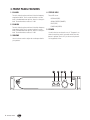
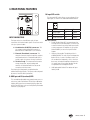
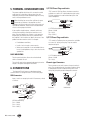
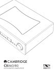
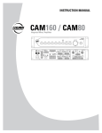
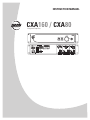
2. INTRODUCTION The CXA160 and CXA80 amplifiers are designed for continuous duty in speech, music, paging and sound reinforcement applications in churches, schools, offices, arenas, hotel meeting rooms, convention centers, recreation facilities and other venues demanding high performance, flexible features and rugged dependability. The CXA160 has a 160 watt power amplifier, and the CXA80 has 80 watts. Apart from this difference in power output, the two models are identical in details and operation. The main line-level input is actively balanced, with a sensitivity control and selection switches for enabling the parallel output, a 10 dB pad, and high-pass filtering. The input and priority input have XLR, TRS, screw-terminal and Phoenix euroblock connectors. The priority input is actively balanced, with a sensitivity control and selection switches for line-level input, mic-level input, mic-level input with 24 VDC phantom power, 10 dB pad, and high-pass filtering. FEATURES • Line input with combination XLR/TRS connector, euro connector, and screw terminals • Priority mic/line input with combination XLR/TRS connector, euro connector, and screw terminals • Parallel output (switch defeatable) for daisy-chaining input signal to other amplifiers or parts of your system (XLR, TRS, euro connector, and screw terminals) • Input is switch-configurable for parallel output on/off, high pass filter on/off, and 10 dB pad in/out • Priority input is switch-configurable for mic or line, phantom power on/off, high pass filter on/off, and 10 dB pad in/out • Priority terminals for manual ducking of main input, as well as automatic ducking when priority signal present • Trim control and level-setting LED on input and priority input When an audio signal greater than -20 dB is present at the priority input, or when an external priority switch is pressed, the main input is automatically muted, and the priority input will play. • Front panel EQ adjustment of bass and treble A parallel output allows the line-level input signal to be daisy-chained to feed other amplifiers or parts of your system. • Front panel power switch Output modes include 4 ohm constant impedance, and constant voltage 25 V, 70 V and 100 V. The smart output stage is fully protected against permanent damage caused by overloading, shorts, and extreme temperatures. The universal power supply will operate from 100 VAC to 240 VAC, 50/60Hz, supplied by a detachable IEC power cord. • Front panel master level control • Front panel overload, signal, fault and power-on LEDs • External volume control (with user-supplied 10k pot) • External fault relay terminals • CXA160: 160 watt rms, convection cooled • CXA80: 80 watt rms, convection cooled • 4 ohm - 25 V - 70 V - 100 V screw terminal outputs Rear panel terminals are provided for connecting an external 24 VDC backup battery, with automatic switching if the AC mains fails. • Global high-pass filter The front panel provides power on/off, a master volume control, and bass and treble controls. Status LEDs indicate signal present, signal overload, fault and power on. • Automatic switching to 24 VDC backup power input • Universal power supply, 100 VAC–240 VAC, 50–60 Hz • 2 RU rack-mountable APPLICATIONS • Foreground/background music systems • Paging systems • Continuous-duty applications • Sound reinforcement systems CXA160 / CXA80 – 3. FRONT PANEL FEATURES 1. EQ-LOW Turn this clockwise to boost the level of the low-frequency range below 100 Hz. Turn it counter-clockwise to cut the level. In the detented center position, there is no change in level. The maximum boost and cut is 12 dB. 2. EQ-HIGH Turn this clockwise to boost the level of the high-frequency range above 10 kHz. Turn it counter-clockwise to cut the level. In the detented center position, there is no change in level. The maximum boost and cut is 12 dB. 3. VOLUME Use this volume control to adjust the sound output level to your speakers. 4. STATUS LEDS These LEDs show: OVERLOAD (RED) SIGNAL PRESENT (AMBER) FAULT (RED) POWER ON (GREEN) 5. POWER Use this switch to turn the unit on or off. The power is on when the top of the switch is pressed, and off when the bottom is pressed. Turn it off if you are not using the unit for long periods of time. 1 – CXA160 / CXA80 2 3 4 5 4. REAR PANEL FEATURES 10. Input DIP switch 9 10 6 7 8 INPUT CONNECTORS The Input section has four different styles of input connections for line-level audio signals. Choose one which suits your system the best: 6. Combination XLR/TRS connector. This can accept a male balanced XLR connector, a balanced TRS or unbalanced TS 1/4" connector. 7. Phoenix (Euroblock) connector. This three-pin connector accepts the positive, negative and ground terminals of a balanced audio line. It accepts a push-in connector for easy installation. 8. Terminal strip. This three-terminal connector accepts the positive, negative and ground terminals of a balanced audio line. Secure the connections with the screws. Each input style is designed to accept balanced or unbalanced line-level signals. The input can be configured by means of the DIP-switch (see below). This three-pole DIP-switch allows you to configure all four input types, as shown in this table and the details below. DIP # Purpose DOWN UP 1 Parallel Enable OFF Enabled 2 High Pass Filter Enabled OFF 3 –10 dB Pad Enable OFF Enabled DIP switch details: 1. Parallel Enable. Select UP if you want there to be an output from the Parallel Output. This allows you to send a line-level copy of the audio input signals to other components or amplifiers in your system. Select DOWN if you are not using the Parallel Outputs. 2. High-pass filter enable. The default position is enabled (DOWN). This rolls off the low frequencies below 120 Hz, at a rate of 12 dB per octave. Use this to reduce low frequencies, such as from low bass notes, microphone handling and stage noise. It is useful when using smaller speakers that do not reproduce the low frequencies well. 3. 10 dB pad enable. Select UP to reduce the input level by 10 dB. 9. GAIN pot and OL (overload) LED This screwdriver-adjustable rotary potentiometer acts as a trim control, and a red indicator LED will light 3 dB before clipping. With normal source material playing, adjust the pot until the LED lights only occasionally during the loudest moments of your program. CXA160 / CXA80 – 15. Priority DIP switch 14 11 12 15 16 13 PRIORITY CONNECTORS When a signal above –20 dB is detected at the priority input, the main input is muted. This is useful for making announcements, as the music program is then automatically muted. This muting can also be accomplished manually by connecting a user-supplied, normally open, dry contact closure switch to the priority screw terminals. The Priority input has four different styles of input connections for microphone-level or line-level audio signals. Choose one which suits your system the best: 11. Combination XLR/TRS connector. This can accept a male balanced XLR connector, a balanced TRS or unbalanced TS 1/4" connector. 12. Phoenix (Euroblock) connector. This three-pin connector accepts the positive, negative and ground terminals of a balanced audio line. It accepts a push-in connector for easy installation. 13. Terminal strip. The three-terminal connectors labeled +, –, and GND, accept the positive, negative and ground terminals of a balanced audio line. Secure the connections with the screws. Each priority input style is designed to accept balanced or unbalanced microphone-level, or line-level signals. The priority input can be configured by means of the DIP-switch (see below). 14. GAIN pot and OL (overload) LED This screwdriver-adjustable rotary potentiometer acts as a trim control, and a red indicator LED will light 3 dB before clipping. With normal priority source material playing, adjust the pot until the LED lights only occasionally during the loudest moments of your program. – CXA160 / CXA80 This five-pole DIP-switch allows you to configure all four priority input types, as shown in this table and described below. DIP # Purpose DOWN UP 1 Mic/Line Line Level Mic Level 2 Mic/Line Line Level Mic Level 3 24 V Phantom OFF Enabled 4 High Pass Filter Enabled OFF 5 –10 dB Pad Enable OFF Enabled DIP switch details: 1. Mic/line (line-level is default). Select UP if using a microphone, or DOWN if it is a line-level input such as from a CD or DVD player. Note: You must always set DIP 2 to the same setting as DIP 1. 2. Mic/Line. Set this to whatever DIP 1 is set to. See above for details. 3. Phantom Power. Select UP if using a microphone that requires phantom power, otherwise, it is important to keep this DOWN. 4. High-pass filter enable. The default position is enabled (DOWN). This rolls off the low frequencies below 120 Hz, at a rate of 12 dB per octave. Use this to reduce low frequencies, such as from low bass notes, microphone handling and stage noise. It is useful when using smaller speakers that do not reproduce the low frequencies well. 5. 10 dB pad enable. Select UP to reduce the input level by 10 dB. 16. Priority Terminals Priority functions can be initiated by a user-supplied, normally open, dry contact closure switch (or switches) connected to the terminal strip (PRI GND, PRI 1). Connecting one leg of the switch to the PRI GND screw and the other side to PRI 1 prepares the circuit. Closing the switch actuates the specific priority, allowing the priority input to play. 17 18 21 19 20 22 23 PARALLEL OUTPUT CONNECTORS These outputs allow you to send a copy of the input signals to another amplifier or component in your system. The output is not affected by the volume or EQ controls. There will only be an output here if the Input DIP switch Pin 1 is set in the UP position (see page 5 for details). The output has four different styles of connections. Choose one that suits your system the best: 17. XLR connector. This can accept a female balanced XLR connector. 18.TRS connector. This can accept a balanced TRS or unbalanced TS 1/4" connector. 19. Phoenix (Euroblock) connector. This three-pin connector accepts the positive, negative and ground terminals of a balanced audio line. It accepts a push-in connector for easy installation. 20. Terminal strip. The three-terminal connectors labeled +, –, and GND, accept the positive, negative and ground terminals of a balanced audio line. Secure the connections with the screws. 21. Low Cut Filter Press this button in to engage the low-cut filter on the output of the amplifier. It is fixed at 100 Hz with a 12 dB slope per octave, and it serves to minimize transformer saturation in constant voltage systems. Frequencies below 100 Hz are attenuated at a rate of 12 dB per octave. 22. External Volume Control This terminal is provided for remote volume control. If you connect a (user-supplied linear-taper 10K pot), you can remotely control the volume of the amplifier in the same way that the front panel volume control does. 23. Fault Relay If a fault is detected in the amplifier section, the positive terminal of this external connector is energized. This external connector can be used to connect to an external device to initiate a “fault” action as dictated by the user. Additionally, the “fault” LED on the front of the amplifier is lit. CXA160 / CXA80 – 26 24 HIGH IMPEDANCE If you are using a constant-voltage distributed speaker system, connect either the 25 V, 70 V, or 100 V output terminal to the "+" side of the speaker system, and connect the upper "GND" output terminal to the "–" side of the speaker system. The voltage of your speakers must equal the voltage of the amplifier's output terminal ( 25 V, 70 V, or 100 V). CAUTION: Make sure that you do not overload the amplifier. This may cause overheating to the amplifier, and possible damage to your speakers. To avoid overloading, make sure that the taps on the speakers add up to no more than 80% of the rated power of the amplifier being used (CXA160: 128 watts, CXA80: 64 watts). For example, for the CXA160, you could use a maximum of 12 speakers with 10 watt taps (12x10 = 120 watts). For further protection, use these figures as the maximum power sum of all the speaker taps: CXA160: 100 watts, CXA80 50 watts. 25 24. Output Connectors This is a five-position barrier strip for connection of speaker loads. Each terminal accepts bare wire from 22 AWG to 10 AWG, or spade lugs sized for the same range of conductors. Terminals are provided for 4 ohm low-impedance loads or 25, 70 and 100 Volt high-impedance loads. All outputs with the exception of the 4 ohm output are transformer isolated. CAUTION: To prevent the risk of electric shock, never touch the bare wires coming from the OUTPUT TERMINALS of the amplifier when it is switched on. When the connections have been made, insulate the 25 V, 70 V, and 100 V terminals of the amplifier using the protective cover supplied. GND and 25V are used to connect a string of 25V speakers. Use Class II wiring: LOW IMPEDANCE To connect a speaker directly, connect the lower GND terminal to the negative post of your speaker, and connect the 4 ohm terminal to the positive post. 0 Make sure that your average speaker impedance is not less than 4 ohm, as this may overload the amplifier. The speaker output connectors are screw terminals. Use 16 or 18 gauge wire for connecting the amplifier outputs to the speakers. Strip the wire back about 3/8" inch, loosen the screw enough to loop the wire around the shaft of the screw (clockwise), and tighten down the screw with a screwdriver. – CXA160 / CXA80 + 0 25V 0 25V GND and 70V are used to connect 70V speakers. Use Class II wiring: 0 - 25V 70V 0 70V 0 70V GND and 100V are used to connect 100V speakers Use Class II wiring: 0 100V 0 100V 0 The unit seamlessly switches to the backup supply if there's a power loss, allowing safety instructions and emergency communications to continue. When both AC power and 24 VDC power are connected, the AC power is used and no current is drawn from the DC supply. 100V Note: The unit will not charge the battery, so you should have a dedicated charging system. Note also, that when running on DC power, the output is lower than when running on AC power. 25. AC Power The CXA160 and CXA80 are fitted with a detachable IEC socket for AC input. Each unit is fitted with a universal power supply, allowing it to operate from any AC mains supply from 100 to 240 VAC, 50-60 Hz. A 6-foot U-Ground to IEC power cable is supplied. An integrated, removable, AC input fuse is fitted just below the IEC socket. To remove or inspect the fuse, first unplug the power cord from the AC socket. Then use a small screwdriver to gently pry open the rectangular fuse holder and inspect or replace the fuse. Replacement fuses must be of the same rating as the original fuse. Low voltage fuses are located internally. 26. DC Power These terminals allow the amplifier to be powered using 24 VDC emergency power supplies. 24 VDC The unit will automatically switch to external DC battery power if your local AC power fails. You will need to connect an external 24 Volt battery to the DC battery terminals. Make absolutely sure the positive post of your battery connects to the positive terminal, and the negative post connects to the negative terminal. To minimize the voltage drop across the wires and prevent overheating, use at least 14 AWG insulated wire. CXA160 / CXA80 – 5. THERMAL CONSIDERATIONS The power amplifier within the unit is convection cooled rather than fan cooled. Heat is drawn away from the amplifier by the heatsink and radiated through the cooling vents in the top and bottom cover. When installing, be sure to allow sufficient air space around the top and rear of the amplifier to allow adequate cooling for the heatsink. Leave at least one rack space above and below, and at least 6 inches behind the chassis to allow proper ventilation. If the amplifier should overheat, a thermal switch turns off the power amplifier, allowing the heatsinks to cool down. Once the amplifier has cooled to a safe operating temperature, the thermal switch resets and reactivates the amplifier. If this should occur, identify the cause of the problem and take corrective action. For example: • Provide better ventilation, • Install a fan in the rack to move more air, 1/4" TRS Phone Plugs and Jacks “TRS” stands for Tip-Ring-Sleeve, the three connections available on a stereo 1/4" or balanced phone jack or plug. TRS jacks and plugs are used for balanced signals and stereo headphones: RING SLEEVE SLEEVE RING TIP TIP RING TIP SLEEVE 1/4" TRS Balanced Mono wiring: Sleeve = Shield Tip = Hot (+) Ring = Cold (–) 1/4" TS Phone Plugs and Jacks “TS” stands for Tip-Sleeve, the two connections available on a mono 1/4" phone jack or plug. They are used for unbalanced signals. SLEEVE • Make sure the amplifier is not overloaded with too low of a load impedance or by a short circuit on the speaker line. SLEEVE TIP TIP TIP SLEEVE RACK MOUNTING The front panel rack holes allows the unit to be fitted within a standard 19" rack. The unit still needs to be supported underneath, due to the weight of the power and output transformers. 6. CONNECTIONS The Input and Priority Input use a dual-purpose input connector which can accept XLR and 1/4" TRS and TS plugs. 1/4" TS Unbalanced Wiring: Sleeve = Shield Tip = Hot (+) Phoenix-type Connectors These connectors use small screws to clamp the wires in place. They can be balanced, using three conductor wiring, or unbalanced using two-conductor wiring and a small wiring link joining the ground and negative connector. XLR Connectors Inputs 1 and 2 can accept 3-pin male XLR connectors, wired as follows: 1 2 3 1 2 3 2 SHIELD HOT COLD SHIELD COLD 3 HOT 1 3 Pin 3 = Cold (–) 10 – CXA160 / CXA80 2 SHIELD COLD 2 XLR Balanced Wiring Pin 1 = Shield Pin 2 = Hot (+) Balanced 1 3 1 HOT Unbalanced AC Line 70V Loudspeakers Backup Battery 24 VDC Line-level output to the input of another CXA160 (for example) Paging Priority Switch AM/FM Tuner or CD Player Paging Microphone 7. TYPICAL HOOKUP DIAGRAM CXA160 / CXA80 – 11 8. SPECIFICATIONS Audio Input and Proximity input Input Type Input Impedance Input Gain Trim Range: Maximum Input Level: Nominal Input Level: Dynamic Range Phantom Power Frequency Response: Total Harmonic Distortion EQ Balanced Differential, Unbalanced 30 kΩ (Bal, Line-In) 2.7 kΩ (Bal, Mic-In) –3 dB to 40 dB (Mic Input) –23 dB to 20 dB (Line Input) +19 dBV 0 dBV 105 dB 24 V 20 Hz - 20 kHz, + 1 dB > 0.1% 20 Hz - 20 kHz @ 0 dBV Butterworth, ±12 dB fixed at 100 Hz ±12 dB fixed at 10 kHz Power Amplifier CXA80 Output Power at 1% THD @ 1 kHz: 80 W @ 100 V 80 W @ 70 V 80 W @ 25 V 80 W @ 4 Ω CXA160 Output Power at 1% THD @ 1 kHz: 160 W @ 100V 160 W @ 70V 160 W @ 25 V 160 W @ 4 Ω Total Harmonic Distortion: < 0.15% (100 V, 70 V, 25 V & 4 Ω modes) Power Bandwidth (at -1 dBr, all modes): 40 Hz - 15 kHz (+0 dB –3 dB) Signal to Noise ratio: 95 dBV Protection: Heatsink Overtemp, DC offset, Short Circuit AC Line Input Power ~100 VAC to 240 VAC 50/60Hz 200W AC Input Low Voltage Detector threshold 70% of Nominal Line Physical Specifications Height (Excluding Feet): 3.46 in/88 mm Width (Overall): 19.00 in/483 mm Depth (Rear side of Rack ear to Rear panel, excluding connectors): 15.00 in/381 mm CXA80 Weight: Net 17.7 lb/7.9 kg Shipping 22.8 lb/10.2 kg CXA160 Weight: Net 19.7 lb/8.8 kg Shipping 24.9 lb/11.1 kg Operating Temperature Range –10°C to 45°C, 14°F to 113°F 12 – CXA160 / CXA80 DISCLAIMER EAW Commercial continually engages in research related to product improvement, new materials, and production methods. Design refinements are introduced into existing products without notice as a routine expression of that philosophy. For this reason, any current EAW Commercial product may differ in some respect from its published description, but will always equal or exceed the original design specifications unless otherwise stated. “EAW Commercial” is a trademark of LOUD Technologies Inc. All other brand names mentioned are trademarks or registered trademarks of their respective holders, and are hereby acknowledged. CXA160 / CXA80 – 13 Phoenix Connector Phoenix Connector Screw Terminal Phoenix Connector External Priority Switch (option) XLR/TRS Combo PRIORITY Screw Terminal XLR/TRS Combo INPUT Screw Terminal XLR TRS PARALLEL OUTPUT Parallel Enable DIP 1 High Pass Mic/ Line DIP 3 Mic/ Line DIP 2 Pad Enable (-10 dB) DIP 1 DIP 2 BLOCK DIAGRAM 24V Phantom DIP 3 Trim High Pass DIP 4 DIP 5 Pad Enable (-10 dB) Trim Priority Threshold Detector 24 VDC BACKUP SUPPLY INPUT PRIORITY MASTER VOLUME CONTROL LOW EQ HIGH EQ UNIVERSAL POWER SUPPLY EXTERNAL VOLUME CONTROL OPTION REMOTE VOLUME HIGH PASS FAULT RELAY AMPLIFIER MONITOR BOARD DC SUPPLY RAILS POWER AMP OUTPUTS 4 OHM, 25V, 70V, 100V 9. SERVICE INFORMATION In the event that your CXA160 or CXA80 should require servicing, please follow these instructions: 1. Call EAW Commercial Tech Support at 1-888-337-7404, 7 am to 5 pm PST (Monday-Friday), to verify the problem and obtain a Return Authorization (RA) Number. Be sure to have the serial number of the unit when you call. You must have a Return Authorization Number in order to obtain warranty service at the factory or at an authorized service center. You can also email EAW Commercial Tech Support at: [email protected] 2. Pack the unit in its original packaging. THIS IS VERY IMPORTANT. LOUD Technologies is not responsible for any damage that occurs during shipping due to nonconventional packaging. Original packaging helps to minimize the possibility of shipping damage. 3. Include a legible note stating your name, (no P.O. boxes), daytime phone number, Return Authorization Number, and a detailed description of the problem, including how we can duplicate it. 4. Write the Return Authorization Number in BIG BOLD PRINT on the top of the box. 5. Tech Support will tell you where to ship the unit when you call for an RA Number. We suggest insurance for all forms of cartage. 14 – CXA160 / CXA80 10. EAW COMMERCIAL WARRANTY Warranty: LOUD Technologies Inc. requires its authorized EAW Commercial distributors to abide by the following warranty terms for all EAW Commercial brand products (all dates are from the date of delivery from an Authorized EAW Commercial Distributor to the end user/installation site): Loudspeakers – 5 years; Active Electronics – 5 years; Accessories – 2 years. What Is Covered: Defects in workmanship and materials and against malfunctions. EAW Commercial distributors must remedy all such defects and malfunctions without charge for parts or labor if the warranty applies. Final determination of warranty coverage lies solely with each authorized EAW Commercial distributor. What Is Not Covered: This warranty does not extend to damage or malfunctions resulting from, but not limited to, shipment, improper installation, misuse, neglect, abuse, normal wear, accident, or to any product on which the serial number has been modified or removed. Exterior defects in or damage to the exterior appearance are specifically excluded from this warranty. EAW Commercial distributors shall not be liable for incidental or consequential damages resulting from the use of EAW Commercial products. Repairs and/or modifications by other than an Authorized EAW Commercial Distributor automatically voids this warranty. CXA160 / CXA80 – 15 EAW Commercial A LOUD Technologies Inc. Company EAW Commercial | One Main Street | Whitinsville, MA 01588 USA | TEL toll free within US/Canada 888.337.7404 TEL outside US 425.892.6503 | FAX 425.485.1152 | www.eawcommercial.com © 2007 LOUD Technologies Inc. All Rights Reserved.