1
MX1 Single Channel MPEG-2 IRD
Operation Manual
Thank you for purchasing the MX1 Single MPEG-2 IRD.
This manual has been written to provide all relevant instructions for operating your MX1 Single MPEG-2
IRD. We recommend that you read these instructions before attempting to install or operate your MX1 to
ensure the maximum benefit to your customers.
A.D.I. Video Technologies Ltd. believes the information contained in this publication is accurate as of its
latest printing date and reserves the right to make changes in specifications and information without prior
notice. A.D.I. Video Technologies is not responsible for any inadvertent errors.
The terms and conditions governing the sales of A.D.I. Video Technologies products and the licensing and
use of software consist solely of those set forth in the contracts between A.D.I. Video Technologies and its
customers. No representation or other affirmation of fact contained in this publication, including but not
limited to statements regarding capacity, response time performance, suitability for use or performance of
products described herein shall be deemed to be a warranty by A.D.I. Video Technologies for any purpose
or give rise to any liability by A.D.I. Video Technologies whatsoever.
In no event shall A.D.I. Video Technologies be liable for any incidental, indirect, or consequential damages
whatsoever (including but not limited to loss of profits) arising out of or relating to this publication or the
information contained in it, even if A.D.I. Video Technologies has been advised, knew, or should have
known of the possibility of such damages.
The products described in this document are confidential and proprietary of A.D.I. Video Technologies or
its licensors.
No part of his document may be reproduced in any form, including by electronic retrieval systems,
without prior written permission of A.D.I. Video Technologies.
©Copyright 2005 by A.D.I. Video Technologies, Ltd.
All rights reserved.
Table of Contents
About this Manual ............................................................................. iii
Organization of this Manual ................................................................... iii
Conventions Used in this Manual ............................................................ iii
Chapter 1 Introduction...................................................................................... 1
Front and Rear Panels............................................................................3
Front Panel .........................................................................................................3
Powering up the MX1 .............................................................................5
The Menu System .................................................................................6
Controlling the Menu ............................................................................................6
Getting Started....................................................................................................7
Chapter 2 Configuring the Input TS ................................................................... 9
Configuring QPSK1 or QPSK2 Input TS .....................................................9
Configuring the IP Input TS .................................................................. 11
Viewing the ASI 1 or ASI 2 Input TS ...................................................... 12
Chapter 3 Configuring the Decoder Parameters ................................................13
Configuring the Decoder Input .............................................................. 14
Configuring the Decoder Work Mode ...................................................... 14
Configuring the Decoder Service Mode.................................................................. 15
Configuring the Decoder PIDs Mode ..................................................................... 16
Configuring the Decoder Video Parameters ............................................. 16
Configuring the Decoder Display............................................................ 18
Configuring the Decoder Output Format................................................................ 18
Configuring the Decoder VBI Functions ................................................................. 19
Configuring the Decoder Audio .............................................................. 20
Chapter 4 Configuring the Output TS ................................................................23
Configuring the Output TS_OUT_2 ......................................................... 23
Configuring the TS_OUT_2 CAM Parameters .......................................................... 24
Configuring the IP Out ......................................................................... 25
Configuring the Low Speed Data (RS-232) .............................................. 25
Chapter 5 Configuring the CA System ...............................................................27
Configuring the CAM 1 or CAM 2............................................................ 27
MX1 Single Channel MPEG 2 Decoder Operation Manual
i
Configuring the MCD ........................................................................... 29
Enabling or Disabling MCD .................................................................................. 29
Configuring MCD Slot 1 ...................................................................................... 29
To configure the BISS parameters:........................................................ 30
Chapter 6 Viewing the MX1 Status ................................................................... 31
Viewing Alarms................................................................................... 31
Viewing Inputs ................................................................................... 32
Viewing the QPSK1 or QPSK2 Inputs .................................................................... 32
Viewing the ASI 1 or ASI 2 Inputs........................................................................ 34
Chapter 7 Viewing the Unit Configuration ........................................................ 35
Chapter 8 Viewing and Configuring the Communication Settings...................... 37
Viewing the Serial Settings................................................................... 37
Configuring the Network Settings .......................................................... 38
Chapter 9 Configuring Additional Setups .......................................................... 39
Configuring the DVB Input Bit Rate........................................................ 39
Enabling or Disabling High Jitter............................................................ 39
Glossary........................................................................................... 41
ii
MX1 Single Channel MPEG 2 Decoder Operation Manual
About this Manual
This manual contains instructions on the minimum hardware configuration of the MX1.
Where applicable, the additional options for the maximum configuration are indicated.
This manual describes the operation of the MX1 through the LCD screen.
Organization of this Manual
Introduction. This chapter describes the hardware interfaces of the MX1 and the
front and rear panels. It also includes a description of and instructions for working
with the menu system.
Configuring the Input TS. This chapter contains instructions for configuring the
input TS parameters included in the Input Menu.
Configuring the Decoder Parameters. This chapter contains instructions for
configuring the decoder parameters included in the Decoder Menu.
Configuring the Output TS. This chapter contains instructions for configuring the
output TS parameters included in the Output Menu.
Configuring the CA System. This chapter contains instructions for configuring the
Conditional Access system parameters included in the CA System Menu.
Viewing the MX1 Status. This chapter contains instructions for viewing the status of
the MX1 through the Status Menu.
Viewing the Unit Configuration. This chapter contains instructions for viewing the
current configuration of the MX1 through the Unit Config Menu.
Viewing and Configuring the Communication Settings. This chapter contains
instructions for viewing and configuring the settings of the various communication
ports through the Comm Settings Menu.
Configuring Additional Setups. This chapter contains instructions for configuring
additional parameters such as input bit rate and high jitter.
Glossary. The glossary lists and explains the terms and acronyms used throughout
this manual.
Conventions Used in this Manual
Indicates a note.
MX1 Single Channel MPEG 2 Decoder Operation Manual
iii
1
Introduction
The MX1 Single MPEG-2 integrated receiver decoder is designed to reduce cost and
satisfy video, audio, and data requirements of digital broadcast television, cable and
satellite operations.
The MX1 integrated receiver decoder is a fully interoperable decoder for digital media
networks that complies fully with the DVB MPEG-2 standard. It decodes program
services provided by up to four selected transport stream inputs.
The decoder supports a large number of applications. Inputs come from the following
sources:
Satellite – QPSK
DVB/ASI
Outputs include the following:
Analog video
Analog audio
Embedded SDI & Non Embedded SDI
AES/EBU
ASI
MX1 Single Channel MPEG 2 Decoder Operation Manual
1
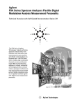
Figure 1 illustrates MX1 applications.
Legend:
LSD
Low speed data over RS-232
HSD
High speed data over RS-422
Other abbreviations
See the Glossary on page 41
Figure 1: MX1 Applications
The decoder supports full transport stream (TS) decryption and is compatible with all
conditional access (CA) modules. Depending on the hardware configuration, the
decoder can also provide embedded CA.
Two slots for Conditional Access Modules (CAM) are provided in the front panel to
enable decryption of received signals and transmission of the signals in the clear to
customers. Depending on the hardware configuration, additional slots are provided in
the rear for the insertion of smart cards (SC) used for the embedded decryption
function.
Other applications of the decoder include the following:
Program Identification (PID) filtering and retransmission
Digital Turnaround (DTA) and video monitoring
Control and monitoring through IP.
In remote mode, all decoder functions can be operated remotely from a PC under
MS-WINDOWS through the IP interface.
In addition to an RS232 or RS422 communication port, the MX1 can provide a General
Purpose Interface (GPI) via a 9-pin D-type connector that allows dry contact alarms.
The GPI depends on the hardware configuration.
In local mode, all decoder functions can be operated through a two-line LCD window
and six buttons on the front panel.
2
MX1 Single Channel MPEG 2 Decoder Operation Manual
Front and Rear Panels
The front panel provides the means to locally configure the MX1. The rear panel
provides the electrical and communications interfaces.
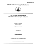
Front Panel
The front panel contains a two-line LCD window and six control buttons, which are
used to configure the MX1.
Figure 3: MX1Front Panel
The LCD window displays two lines of a selected window. The ▲ and ▼ buttons are
used to scroll through the window. The ▲, ▼, ►, and ◄ buttons are used to select
menu entries viewed through the LCD window. The ENTER button is used to save new
configurations during an edit session, while the ESC button is used to discard new
configurations.
The front panel provides two ports for the Conditional Access Modules (CAM), CAM 1
and CAM 2.
The Status LED provides status information for the MX1, as described in Table 1.
Table 1: Status LED Indications
Appearance
Significance
Dark
Power off
Blinking Green
Power up self test
Green
Operational state
Orange
Alarm
Red
Error
MX1 Single Channel MPEG 2 Decoder Operation Manual
3
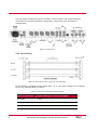
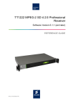
The rear panel contains the power connector, power switch, and communications
connectors for the MX1 hardware configuration, which may vary according to
configuration.
Figure 4: Rear Panel
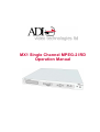
XLR Cable Wiring
Figure 5: Rear Panel 9-Pin D-Type to XLR Connector
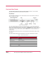
If you connect a computer to MX1 Serial Port 1 or 2, you must configure the computer
port to the settings listed in Table 2.
Table 2: Serial Line Connection Requirements
4
Serial Line Parameter
Required Setting for Connected Computer
Baud Rate
115200
Parity
None
Data Bits
8
MX1 Single Channel MPEG 2 Decoder Operation Manual
Serial Line Parameter
Required Setting for Connected Computer
Stop Bits
1
Flow Control
Xon/Xoff
To use the Ethernet port, you must configure the IP address and mask for both your
computer and the MX1. For information on configuring the IP address and mask, refer
to Configuring the Network Settings on page 38.
Features in the Full Feature Hardware Configuration
When the MX1 contains the maximum configuration, four additional BNC connectors
can accommodate more input TSs, which can be four QPSK sources.
The maximum hardware configuration includes the following features:
Two Video – Composite
Two SDIs with embedded audio or SDI without Embedded Audio
Two Audio – Stereo, AES/EBU
Inputs — One QPSK, two ASI, one IP
Outputs — Two ASI, one A/V channels
Computer Communication – 1 RS232, 1 RS422
Powering up the MX1
To power up the MX1, connect the power to the AC main and turn on the power switch.
Figure 6 shows the power connector and switch on the rear panel of the MX1.
Figure 6: Power Connector and Switch
To verify correct performance, observe the changes in the Status LED on the front
panel (Figure 3). Refer to Table 1 for an explanation of the status indications in the
Status LED.
During power up, the Power Up Menu is displayed in the LCD Window for five seconds.
After five seconds, the first two lines of the Main Menu are displayed. For more
information refer to Getting Started on page 7.
MX1 Single Channel MPEG 2 Decoder Operation Manual
5
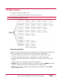
The Menu System
This section describes the MX1 menu.
The menu is organized hierarchically as illustrated in Figure 8.
Each rectangle represents a menu.
Figure 8: Menu System
Controlling the Menu
The MX1 is configured through the front panel buttons. The following six buttons are
used to navigate the menu system and configure available parameters:
▼ scrolls downward through a menu. In edit mode, it is used to edit values.
▲ scrolls upward through a menu. In edit mode, it is used to edit values.
► enters submenus or edit mode. In edit mode, it moves the cursor to the right
column.
◄ moves the cursor one position to the left in edit mode.
ENTER enters into a submenu. If there is no submenu, pressing ENTER saves your
changes, exits the current menu, and enters the next higher menu.
ESC exits from a menu without saving information. In submenus, pressing ESC
enters a higher menu.
6
MX1 Single Channel MPEG 2 Decoder Operation Manual
The LCD window shows only two consecutive lines of a selected menu. A blinking
rectangle █ indicates the position in the cursor.
The Main Menu and lower submenus contain options you can select using the buttons.
Menus at the bottom of the hierarchy contain information that you can edit by using
the arrow buttons. Data is displayed in some of the menus. Brackets in a menu
indicate whether the data can be modified. The following types of brackets are used:
{ } – data cannot be modified
< > – data can be modified
Getting Started
After the MX1 powers up, the first two lines of the Main Menu appear. Figure 10
illustrates the Main Menu screen.
Figure 10: Main Menu Screen
To view the rest of the menu, use the scroll buttons. Figure 12 illustrates the full Main
Menu.
Input
Decoder
Output
CA System
Status
Unit Config
Comm Settings
Additional Setups
Figure 12: Full Main Menu
Table 3 lists the references in this manual for instructions on configuring the Main
Menu options.
Table 3: Reference Table for Main Menu Option Configuration
Main Menu Option
Refer To
Input
Configuring the Input TS on page 9
Decoder
Configuring the Decoder Parameters on page 13
Output
Configuring the Output TS on page 23
MX1 Single Channel MPEG 2 Decoder Operation Manual
7
8
Main Menu Option
Refer To
CA System
Configuring the CA System on page 27
Status
Viewing the MX1 Status on page 31
Unit Config
Viewing the Unit Configuration on page 35
Comm Settings
Viewing and Configuring the Communication Settings
on page 37
Additional Setups
Configuring Additional Setups on page 39
MX1 Single Channel MPEG 2 Decoder Operation Manual
2
Configuring the Input TS
The Input Menu allows configuration of the QPSK parameters and shows the status of
the ASI input transport streams (TSs).
To access the Input Menu, select Input from the Main Menu. Figure 14 illustrates the
Input Menu screen.
Figure 14: Input Menu Screen
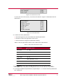
To view the rest of the menu, use the scroll buttons. Figure 16 illustrates the full Input
Menu.
QPSK1
QPSK2
ASI 1
ASI 2
IP
{
{
{
{
{
SYNC
SYNC
SYNC
SYNC
SYNC
ON}
ON}
ON}
ON}
ON}
Figure 16: Full Input Menu
Configuring QPSK1 or QPSK2 Input TS
To configure parameters for a QPSK1 or QPSK2 TS input stream:
1. To configure QPSK1 parameters, select Input > QPSK1.
To configure QPSK2 parameters, select Input > QPSK2.
The QPSK Input Menu screen appears.
MX1 Single Channel MPEG 2 Decoder Operation Manual
9
Figure 18: QPSK Input Menu Screen
To view the rest of the menu, use the scroll buttons.
Frequency
LNB Freq
Sym Rate
FEC
Polarity
22 KHz
<12245.00>
<10600>
<27500>
<2/3>
<Horizontal>
<ON>
Figure 19: Full QPSK Input Menu
2. Scroll to the parameter you wish to configure and press ► to move the cursor to the
right column.
3. To edit the parameter:
Press ► to move right one number or letter.
Press ◄ to move left one number or letter.
Press ▲ to select other values or increase a number. This depends on the
parameter.
Press ▼ to select other values or decrease a number. This depends on the
parameter.
Table 5 lists the permitted values of the QPSK parameters.
Table 5: QPSK Parameter Values
Parameter
Type
Lower Limit
Upper Limit
Frequency
Kuband
10.75 GHz
12.75 GHz
Cband
3.0 GHz
4.200 GHz
Lband
.950 GHz
2.150 GHz
10.000 GHz
10.000 GHz
11.000 GHz
11.000 GHz
11.300 GHz
11.300 GHz
11.700 GHz
11.700 GHz
LBN Frequency
10
MX1 Single Channel MPEG 2 Decoder Operation Manual
Parameter
Type
Lower Limit
Upper Limit
Universal LNB
10.600 GHz High Band
9.7500 GHz Low Band
CBand
5.150 GHz
5.150 GHz
Sym (Symbol) Rate
1 MBaud
45 MBaud
FEC
1/2, 2/3, 3/4, 5/6, 7/8, or Auto
Polarity
Horizontal, Vertical, None
22 KHz
ON, OFF
4. To configure additional parameters, press ◄ and repeat steps 2 - 3.
5. To save your changes, press ENTER. The LCD displays the first two lines of the
Main Menu.
To discard your changes, press ESC. The LCD displays the first two lines of the Main
Menu.
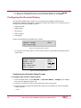
Configuring the IP Input TS
To configure parameters for IP TS input stream:
1. Select Input > IP.
2. Define the PORT NUMBER.
PORT NUMBER
IP TYPE
<11111>
<MULTICAST>
3. Choose the IP Type: UNICAST or MULTICAST.
4. In case MULTICAST chosen you should change the MULTI IP according to
source stream unit IP.
UNI
MULTI
<10.10.10.10>
<225.20.20.20>
10.10.10.10 IS THE CURRENT UNIT IP ADDRESS.
225.20.20.20 IS THE SOURCE STREAM UNIT IP ADDRESS.
To edit the parameter:
Press ► to move right one number or letter.
Press ◄ to move left one number or letter.
Press ▲ to select other values or increase a number. This depends on the
parameter.
MX1 Single Channel MPEG 2 Decoder Operation Manual
11
Press ▼ to select other values or decrease a number. This depends on the
parameter.
To save your changes, press ENTER. The LCD displays the Input TS Menu.
To discard your changes, press ESC. The LCD displays the Input TS Menu.
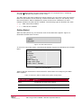
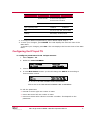
Viewing the ASI 1 or ASI 2 Input TS
The ASI Input Menu lists the input channels of the MX1.
The parameters in the Input Menu cannot be modified. The numbers on the left side of
the menu accompanying the inputs indicate whether the input is Input 1 or Input 2.
To view the ASI Input TS:
1. From the Main Menu, select Input > ASI 1 or ASI 2. The ASI Input Menu screen
appears.
Figure 20: ASI Input Menu Screen
Channels are listed in the ASI Input Menu only when the ASI parameter in the Input
Menu (Figure 16) has the value SYNC ON. When the ASI parameter in the Input Menu
has the value SYNC OFF, the ASI Input Menu screen displays No Services.
12
MX1 Single Channel MPEG 2 Decoder Operation Manual
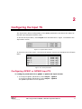
3
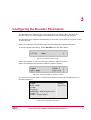
Configuring the Decoder Parameters
The Decoder Menu displays the service and service provider name. Through the
Decoder Menu, you can configure the parameters for controlling the decoder.
The Decoder Menu appears automatically on the MX1 screen after the system is idle
for two minutes.
Figure 21 illustrates the Decoder Menu screen listing the available decoders.
To access the Decoder Menu, select Decoder from the Main Menu.
Figure 21: Decoder Menu Screen
Select the decoder to view the Decoder Submenu options screen.
Figure 23 illustrates the Decoder Submenu options screen.
Figure 23: Decoder Submenu Options Screen
To view the rest of the menu, use the scroll buttons. Figure 25 illustrates the full
Decoder Submenu.
Input
{QPSK}
{Service}
Work Mode
Video
Display
Embedded Audio(optional)
Audio 1
Audio 2(optional)
Figure 25: Full Decoder Submenu
MX1 Single Channel MPEG 2 Decoder Operation Manual
13
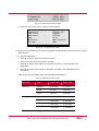
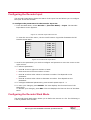
Configuring the Decoder Input
The Decoder Input Menu shows the status of the input TSs and allows you to configure
the input TS for the decoder.
To configure the parameters for the Decoder Input TS:
1. From the Main Menu, select Decoder > [Decoder Name] > Input. The Decoder
Input Menu screen appears.
Figure 27: Decoder Input Menu Screen
To view the rest of the menu, use the scroll buttons. Figure 28 illustrates the full
Decoder Input Menu.
QPSK1
QPSK2
ASI 1
ASI 2
IP
CAM1
CAM2
{
{
{
{
{
{
{
SYNC ON
SYNC ON
SYNC ON
SYNC ON
SYNC ON
ASI 1
QPSK1
}
}
}
}
}
}
}
Figure 28: Full Decoder Input Menu
2. Scroll to the parameter you wish to configure and press ► to move the cursor to the
right column.
3. To edit the parameter:
Press ► to move right one number or letter.
Press ◄ to move left one number or letter.
Press ▲ to select other values or increase a number. This depends on the
parameter.
Press ▼ to select other values or decrease a number. This depends on the
parameter.
4. To configure additional parameters, press ◄ and repeat steps 2 - 3.
5. To save your changes, press ENTER. The LCD displays the first two lines of the
Main Menu.
To discard your changes, press ESC. The LCD displays the first two lines of the Main
Menu.
Configuring the Decoder Work Mode
The Decoder Work Mode Menu allows you to define the service in a TS. The following is
a list of possible work modes:
14
MX1 Single Channel MPEG 2 Decoder Operation Manual
Service Mode. You select the service by Service ID and name, and the MX1 uses the
PIDs in the System Information (SI) table to identify the Elementary Streams (ES)
that comprise the service. A PID is a unique identifier for the ES.
PIDs Mode. You define the service by providing a Service ID and the PIDs for each
of the following streams:
PCR
Video
Audio
Audio Type
Teletext
Subtitles
Figure 30 illustrates the Work Mode Menu screen.
Figure 30: Work Mode Menu Screen
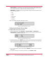
Configuring the Decoder Service Mode
To configure the decoder service mode:
1. From the Main Menu, select Decoder > [Decoder Name] > Work Mode >
Service Mode. The Service Mode Menu appears. If more than two services exist,
scroll down to view additional services.
Figure 32: Service Mode Menu Screen
2. To select a service, press ENTER. If the service has more than one audio PID, the
Service Mode Submenu appears showing the choices. If more than two audio PIDs
exist, scroll down to view additional audio PIDs.
Figure 33: Service Mode Submenu Screen
3. From the Main Menu, select a PID and press ENTER. The MX1 returns to the Work
Mode Menu.
4. To continue working in the Decoder Submenu, press ENTER or ESC.
MX1 Single Channel MPEG 2 Decoder Operation Manual
15
Configuring the Decoder PIDs Mode
The PIDs Menu allows you to manually assign Program Identification strings to the
elementary streams within a TS.
To configure the PIDs Mode:
1. From the Main Menu, select Decoder > [Decoder Name] > Work Mode > PIDs
Mode. The PIDs Mode Menu screen appears.
Figure 34: PIDs Mode Menu Screen
To view the rest of the menu, use the scroll buttons. Figure 28 illustrates the full
PIDs Mode Menu.
PCR
Video
Audio
Audio Type
Teletext
Subtitles
Service
<0245H>
<0245H>
<0267H>
<AC3 >
<0000H>
<0068H>
<0067H>
Figure 35: Full PIDs Mode
2. To edit the parameter:
Scroll down or up to select the desired input.
Press ► to enter the value field.
Press the arrow buttons to edit the value.
3. To edit additional parameters, press ◄ until the cursor is in the left part of the
screen and repeat steps 2 to 3 until you are finished.
4. Press ENTER to save your changes. The Work Mode Menu appears.
Press ESC to discard your changes. The Work Mode Menu appears.
5. Press ESC to return to the Decoder Submenu.
Configuring the Decoder Video Parameters
The Decoder Video Menu allows you to configure the video stream output within a TS.
To configure the video output:
1. From the Main Menu, select Decoder > [Decoder Name] > Video. The Video
Menu screen appears.
16
MX1 Single Channel MPEG 2 Decoder Operation Manual
Figure 36: Video Menu Screen
To view the rest of the menu, use the scroll buttons. Figure 37 illustrates the full
Video Menu.
Horizontal
Vertical
Aspect Ratio
Frame Rate
Profile
Level
Video Format
{720}
{576}
{4:3}
{ 25}
{ MP}
{ ML}
{PAL}
Figure 37: Full Video Menu
2. To edit the video parameters:
Scroll through the menu and select the desired parameter.
Press ► to enter the right side of the menu.
Press ▼ and ▲ to toggle the parameter setting.
Table 7 lists the permitted values of the Video Menu parameters.
Table 7: Video Menu Parameter Values
Parameter
Possible Values
Horizontal
0 – 720
Vertical
0 – 576 for PAL, 0 – 480 for NTSC
Aspect Ratio
4:3, 16:9
Frame Rate
25, 30
Profile
Main (optionally: 4:2:2)
Level
Main
Video Format
PAL, NTSC, undefined
3. Press ENTER to save your changes and return to the left side of the menu.
Press ESC or ◄ to discard the change and return to the left side of the menu.
4. To configure additional parameters, repeat steps 2 - 3 until all desired parameters
are configured.
MX1 Single Channel MPEG 2 Decoder Operation Manual
17
5. To save your changes and return to the Decoder Submenu, press ► or ENTER.
To discard your changes and return to the Decoder Submenu, press ESC.
Configuring the Decoder Display
The Decoder Display Menu allows you to configure the display of special text
elementary streams that appear in addition to audio and video in TS. It allows you to
configure the following display options:
Output Format
Aspect Ratio
AR Convert
VBI Functions
Test Signal
Figure 39 illustrates the Display Menu screen.
Figure 39: Display Menu Screen
To view the rest of the menu, use the scroll buttons. Figure 26a illustrates the full
Video Menu.
Output Format
Aspect Ratio
AR Convert
VBI Functions
Test Signal
<Pal>
<4:3>
<LTR_BOX>
<OFF>
Figure 26a Full Display Menu
Configuring the Decoder Output Format
To configure the decoder output format:
1. From the Main Menu, select Decoder > [Decoder Name] > Display. The Display
Menu screen appears (Figure 39).
2. Press ► to move the cursor to the right side of the LCD screen.
3. Press ▼ and ▲ to toggle the parameter setting. The following is a list of possible
output formats:
PAL
18
MX1 Single Channel MPEG 2 Decoder Operation Manual
NTSC
Auto
4. Press ENTER to save your changes and return to the left side of the menu.
Press ESC or ◄ to discard the change and return to the left side of the menu.
5. To save your changes and return to the Decoder Submenu, press ► or ENTER.
To discard your changes and return to the Decoder Submenu, press ESC.
Configuring the Decoder VBI Functions
To configure the Decoder VBI Functions Menu:
1. From the Main Menu, select Decoder > [Decoder Name] > Display > VBI
Functions. The VBI Functions Menu screen appears.
Figure 41: VBI Functions Menu Screen
To view the rest of the menu, use the scroll buttons. Figure 42 illustrates the full
VBI Functions Menu.
Teletext
Closed Caption
WSS
VITS
<OFF>
<None>
<OFF>
<OFF>
Figure 42: Full VBI Functions Menu
2. To edit the parameters:
Scroll to select the desired parameter.
Press ► to move the cursor to the right side of the menu.
Press ▼ and ▲ to toggle the parameter setting.
Table 9 lists the permitted values of the VBI Functions Menu parameters.
Table 9: VBI Functions Menu Parameter Values
Parameter
Possible Values
Teletext
ON, OFF
Closed Caption
None, DVS157, ATSC
WSS
ON, OFF
MX1 Single Channel MPEG 2 Decoder Operation Manual
19
Parameter
Possible Values
VITS
ON, OFF
3. Press ENTER to save your changes and return to the left side of the menu.
Press ESC or ◄ to discard your changes and return to the left side of the menu.
4. To configure additional parameters, repeat steps 2 - 3.
5. Press ENTER to save changes and return to the Decoder Submenu.
Press ESC to discard your changes and return to the Decoder Submenu.
Configuring the Decoder Audio
The Audio menu allows you to configure the audio stream for the decoder.
To configure the Decoder audio:
1. From the Main Menu, select Decoder > [Decoder Name] > Audio. The Audio
Menu screen appears.
Figure 44: Audio Menu Screen
To view the rest of the menu, use the scroll buttons. Figure 45 illustrates the full
Audio Menu.
Mute
Audio Level
STC Offset
Sample Rate
Bit Rate
Coding Mode
Content
Digital Out(optional)
Clipping
<OFF>
<6 dB>
<0 msec>
{50338.7
{16 Kb
{Stereo
{MPEG1
<PCM>
{No Clip
}
}
}
}
}
Figure 45: Full Audio Menu
2. To edit the parameters:
Scroll to the desired parameter.
Press ► to move the cursor to the right side of the menu.
Press ▼ and ▲ to toggle the parameter setting.
Table 11 lists the parameters and their permitted values.
20
MX1 Single Channel MPEG 2 Decoder Operation Manual
Table 11: Audio Menu Parameter Values
Parameter
Possible Values
Mute
ON, OFF
Audio Level
-26 dB to 6 dB
STC Offset
0 – 90 msec (multiples of ten)
Sample Rate
Any value complying with MPEG2 ISO/IEC standards
Note: This value is read-only.
Any value, in Kb
Bit Rate
Note: This value is read-only.
Coding Mode
Stereo, mono, Dolby Surround, mono mix
Note: This value is read-only.
Content
MPEG 1, MPEG 2, AC3 (for Dolby surround), MP3, Undefined
Digital
Out(optional)
PCM / Pass Through
Clipping
No Clip, 24, 22, 20, 18, …, 2 dB
3. Press ENTER to save your changes and return to the left side of the menu.
Press ESC or ◄ to discard your change and return to the left side of the menu.
4. To configure additional parameters, repeat steps 2 - 0.
5. Press ► or ENTER to save changes and return to the Decoder Submenu.
Press ESC to discard your changes and return to the Decoder Submenu.
MX1 Single Channel MPEG 2 Decoder Operation Manual
21
4
Configuring the Output TS
The Output Menu allows you to choose the decoder output. In order to send TSs to
external devices, you must first configure the two output TSs. The first output TS
receives the same TS as the decoder input TS and is therefore read-only in the
Output Menu. The second output TS can use a different input TS.
To access the Output Menu, select Output from the Main Menu. Figure 47 illustrates
the Output Menu screen.
Figure 47: Output Menu Screen
To view the rest of the menu, use the scroll buttons. Figure 49 illustrates the full
Output Menu.
TS_OUT_1
TS_OUT_2
IP OUT
LSData (RS-232)
{QPSK 1 -> CAM 1}
<QPSK2>
<QPSK1>
{None}
Figure 49: Full Output Menu
Configuring the Output TS_OUT_2
To configure the output TS_OUT_2:
1. From the Main Menu, select Output. The Output Menu screen appears (Figure 47).
2. Scroll down to TS_OUT_2 and press ► to move the cursor to the right side of the
LCD screen.
3. Press ▼ and ▲ to toggle the parameter setting. The following is a list of possible
values:
QPSK1
QPSK2
MX1 Single Channel MPEG 2 Decoder Operation Manual
23
ASI 1
ASK 2
CAM 1
CAM 2
If CAM 1 or CAM 2 is selected, the TS_OUT_2 Submenu is displayed to enable
selection of an input stream for decryption. For instructions on configuring the
TS_OUT_2 CAM parameters, see Configuring the TS_OUT_2 CAM Parameters on page
24.
4. Press ENTER to save your changes and return to the left side of the menu.
Press ESC or ◄ to discard your changes and return to the left side of the menu.
5. Press ENTER to save your changes. The Decoder Submenu appears.
Press ESC to discard your changes. The Decoder Submenu appears.
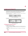
Configuring the TS_OUT_2 CAM Parameters
The TS_OUT_2 CAM parameters need to be configured if you select CAM 1 or CAM 2
as the input to Output 2.
To configure the TS_OUT_2 CAM parameters:
1. Navigate to the TS_OUT_2 Submenu. For instructions, see Configuring the Output
TS_OUT_2 on page 23. The TS_OUT_2 Submenu screen appears.
Figure 51: TS_OUT_2 Submenu Screen
To view the rest of the submenu, use the scroll buttons. Figure 52 illustrates the
full TS_OUT_2 Submenu.
Service
Video PID
Audio PID
Teletext PID
<1BBDH>
<00A0H>
<0052H>
<2000H>
Figure 52: Full TS_OUT_2 Submenu
The value 2000H indicates that no PID exists for Teletext.
2. To edit the parameters:
Press ► to enter the right side of the menu.
Press ▼ and ▲ buttons to edit the PID.
24
MX1 Single Channel MPEG 2 Decoder Operation Manual
Press ENTER to save your changes and return to the left side of the menu.
Press ESC or ◄ to discard your changes and return to the left side of the menu.
To configure additional parameters, repeat steps 2 -
.
Press ► or ENTER to save changes and return to the Output Menu.
Press ESC to discard your changes and return to the Output Menu.
Configuring the IP Out
1. Select OUTPUT.
2. Press ► over IP OUT.
3. Use ▼ and ▲ buttons to change the input or to set it on off.
4. Press ENTER.
5. Change the destination IP address:
IP
<225.20.20.20>
6. Define the port number:
PORT NUMBER
<11111>
7. choose the Mode:
(no change, service filter, Block all, Bypass all)
Mode
Bit Rate
<Service filter>
{ 18 M }
8. If Service filter chosen, press ENTER to select/deselect a service.
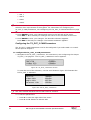
Configuring the Low Speed Data (RS-232)
To configure the low speed data (RS-232):
1. From the Main Menu, select Output. The Output Menu screen appears (Figure 47).
2. Press ▼ to scroll down to LSData (RS-232).
3. Press ► to configure the low speed data (RS-232). The LSData Menu screen
appears.
MX1 Single Channel MPEG 2 Decoder Operation Manual
25
Figure 54: LSData Menu Screen
To view the rest of the menu, use the scroll buttons. Figure 55 illustrates the full
LSData Menu.
Data Input
Data PID
Baud
Format
Flow Cntl
Filtering
<Decoder 1
<2000H
<9600
<MSB First
<None
<Raw Data
>
>
>
>
>
>
Figure 55: Full LSData Menu
4. To configure the parameters:
Press ► to enter the right side of the menu.
Press ▼ and ▲ buttons to change the parameter value.
Table 12 lists the parameters and their permitted values.
Table 12: LSData Menu Parameter Values
Parameter
Possible Values
Data Input
Decoder 1
Data PID
2000H
Baud
1200, 2400, 4800, 9600, 14400, 19200, 38400, 57600, 115200
Format
LSB First, MSB First
Flow Cntl
None, Xon/Xoff
Filtering
RAW Data, PES Data
5. Press ENTER to save your changes and return to the left side of the menu.
Press ESC or ◄ to discard your changes and return to the left side of the menu.
6. To configure additional parameters, repeat steps 4 - 5.
7. Press ► or ENTER to save changes and return to the Output Menu.
Press ESC to discard your changes and return to the Output Menu.
26
MX1 Single Channel MPEG 2 Decoder Operation Manual
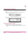
5
Configuring the CA System
The CA System Menu allows you to configure decryption in the decoder and CAM
usage.
To access the CA System Menu, select CA System from the Main Menu. Figure 57
illustrates the CA System Menu screen.
Figure 57: CA System Menu Screen
To view the rest of the menu, use the scroll buttons. Figure 59 illustrates the full CA
System Menu.
CAM 1
CAM 2
MCD
BISS
{Irdeto
}
{ViAccess }
{MCD Off }
Figure 59: Full CA System Menu
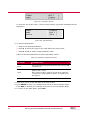
Configuring the CAM 1 or CAM 2
To configure the name, input, and status of the CAM 1 or CAM 2:
1. From the Main Menu, select CA System > CAM 1 or CAM 2. The CAM Menu screen
appears.
MX1 Single Channel MPEG 2 Decoder Operation Manual
27
Figure 61: CAM Menu Screen
To view the rest of the menu, use the scroll buttons. Figure 62 illustrates the full
CAM Menu.
Input
Name
Status
{Irdeto}
<ASI 2 >
{Idle }
Figure 62: Full CAM Menu
2. To edit the parameters:
Scroll to the desired parameter.
Press ► to move the cursor to the right side of the LCD screen.
Press ▼ and ▲ to select a new parameter value.
Table 14 lists the parameters and their permitted values.
Table 14: CAM Menu Parameter Values
Parameter
Possible Values
Name
Cannot be edited. The field shows the name of the CAM
manufacturer.
QPSK1, ASI 1, ASI 2
Input
Note: When the MX1 contains the maximum hardware
configuration, options QPSK2, QPSK3, and QPSK4 may
also appear.
Status
Cannot be edited. The field shows the status of the CAM
3. Press ◄ to return to the left side of the LCD screen.
4. Press ENTER to save your changes and return to the CA System Menu.
Press ESC to discard your changes and return to the CA System Menu.
5. To return to the Main Menu, press ESC.
28
MX1 Single Channel MPEG 2 Decoder Operation Manual
Configuring the MCD
The MCD Menu allows you to add and remove the decrypted services of each CAM.
Figure 64 illustrates the MCD Menu screen.
The MCD feature is only available to users of the MX1 3000 series.
Figure 64: MCD Menu Screen
Enabling or Disabling MCD
To enable or disable MCD:
1. From the Main Menu, select CA System > MCD. The MCD Menu screen appears
(Figure 64).
2. Press ► to move the cursor to the right side of the LCD screen.
3. Press ▼ and ▲ to select a new parameter value. The following are possible values:
MCD OFF. Select this value to disable MCD mode.
MCD ON. Select this value to enable MCD mode.
Press ◄ to return to the left side of the LCD screen.
4. Press ENTER to save your changes and return to the CA System Menu.
Press ESC to discard your changes and return to the CA System Menu.
Configuring MCD Slot 1
To configure MCD Slot 1:
1. From the Main Menu, select CA System > MCD > Slot 1. The MCD Slot Menu
screen appears.
Figure 66: MCD Slot Menu Screen
To view the rest of the menu, use the scroll buttons. Figure 67 illustrates the full
MCD Slot Menu.
MX1 Single Channel MPEG 2 Decoder Operation Manual
29
Mode
Add Service
Remove Service
Reset Slot
<MCD Plus>
Figure 67: Full MCD Slot Menu
2. To edit the Mode parameter, press ► to move the cursor to the right side of the
LCD screen and press ▼ and ▲ to select either MCD Plus or MCD Pro.
To add a service, select Add Service. The Add Service Menu screen appears with a
list of available services. Choose the service you wish to add and press ENTER.
To remove a service, select Remove Service. The Remove Service Menu screen
appears with a list of available services. Choose the service you wish to delete and
press ENTER.
To reset the slot, select Reset Slot.
3. Press ENTER to save your changes and return to the CA System Menu.
Press ESC to discard your changes and return to the CA System Menu.
To configure the BISS parameters:
1. From the Main Menu, select CA System > BISS. The BISS Menu screen appears.
Figure 69: BISS Menu Screen
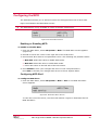
2. Select the desired parameter and press ► to move the cursor to the right side of
the LCD screen.
3. Press ▼ and ▲ to change the parameter to ON or OFF.
4. Press ENTER to save your changes and return to the CA System Menu.
Press ESC to discard your changes and return to the CA System Menu.
Parameters:
30
•
BISS 1 -> Set SW <************> Press ▼ and ▲ to change 12 digits.
•
BISS E -> BISS MODE:
o
Injected ID -> ESW <****************> Press ▼ and ▲ to change
16 digits, and ID <**************> Press ▼ and ▲ to change 14
digits.
o
Buried ID -> ESW <****************> Press ▼ and ▲ to change 16
digits.
MX1 Single Channel MPEG 2 Decoder Operation Manual
6
Viewing the MX1 Status
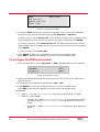
The Status Menu provides information on the alarm and input status. If the Input is
QPSK, the tuner status is also provided.
To access the Status Menu, select Status from the Main Menu. Figure 70 illustrates the
Status Menu screen.
Figure 70: Status Menu Screen
Viewing Alarms
To view the MX1 alarms:
1. From the Main Menu, select Alarms. A list of current alarms for the MX1 system
appears.
Figure 72: List of Alarms
The Alarms list is a scrollable list that displays all of the current alarms for the system.
The alarms appearing on the list differ for each system.
2. Press ESC to return to the Main Menu.
MX1 Single Channel MPEG 2 Decoder Operation Manual
31
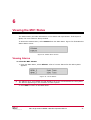
Viewing Inputs
The Status Inputs Menu allows you to view information on the following inputs:
QPSK1
QPSK2
ASI 1
ASI 2
To access the Status Inputs Menu screen, select Status > Input from the Main Menu.
Figure 73 illustrates the Status Inputs Menu Screen.
Figure 73: Status Inputs Menu Screen
To view the rest of the menu, use the scroll buttons. Chyba! Nenalezen zdroj
odkazů. illustrates the full Status Inputs Menu.
QPSK1
QPSK2
ASI 1
ASI 2
IP
{
{
{
{
{
SYNC
SYNC
SYNC
SYNC
SYNC
ON
ON
ON
ON
ON
}
}
}
}
}
Figure 75: Full Status Inputs Menu
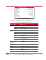
Viewing the QPSK1 or QPSK2 Inputs
To view the QPSK1 or QPSK2 inputs:
1. From the Main Menu, select Alarms > QPSK1 or QPSK2. The Status QPSK Menu
screen appears.
Figure 76: Status QPSK Menu Screen
To view the rest of the menu, use the scroll buttons. Figure 77 illustrates the full
Status QPSK Menu.
32
MX1 Single Channel MPEG 2 Decoder Operation Manual
FREQ
LNB FREQ
SYM RATE
FEC
POLARITY
22 kHz
EB/N0
BER
Gain Marg
Rcv Level
12245.00 MHz
106.00 MHz
275.00 MSmb1
2/3
Horizontal
ON
14.0 dB
2.0000 e-7
7.0 dB
-73
Figure 77: Full Status QPSK Menu
Table 16 lists the parameters and their permitted values.
Table 16: Status QPSK Menu Parameter Values
Parameter
Type
Possible Values
Frequency
Kuband
10.75 - 12.75 GHz
Cband
3.0 - 4.200 GHz
Lband
.950 - 2.150 GHz
LBN
Frequency
10.000 GHz
11.000 GHz
11.300 GHz
11.700 GHz
Universal LNB
10.600 GHz High Band
9.7500 GHz Low Band
CBand
5.150 GHz
Sym
(Symbol)
Rate
1 - 45 MBaud
FEC
1/2, 2/3, 3/4, 5/6, 7/8, Auto
Polarity
Horizontal, Vertical, None
22 KHz
ON, OFF
EB/N0
Signal:Noise ratio
MX1 Single Channel MPEG 2 Decoder Operation Manual
33
Parameter
Type
Possible Values
Bit Error Rate
Note: If the MX1 displays a value of X.XXXX e-3 or
higher (e.g., 2.0000 e-2) check your satellite
connection.
BER
Gain Margin in Eb/N0.
Gain Marg
Note: A value less than 7 dB indicates a critical
state.
Rcv Level
-25 to -65 dbm (dynamic range of the receiver)
2. Press ESC to return to the Main Menu.
Viewing the ASI 1 or ASI 2 Inputs
To view the ASI 1 or ASI 2 inputs:
1. From the Main Menu, select Status > Inputs > ASI 1 or ASI 2. The Status ASI
Menu screen appears.
Figure 79: Status ASI Menu Screen
Table 18 lists the parameters and their permitted values.
Table 18: ASI Menu Parameter Values
Parameter
Possible Values
On. The ASI source is connected and working.
SYNC
Off. The ASI source is unavailable.
188, 204.
Packet Length
The packet length value is determined automatically by
the system.
2. Press ESC to return to the Main Menu.
34
MX1 Single Channel MPEG 2 Decoder Operation Manual
7
Viewing the Unit Configuration
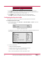
The Unit Configuration Menu displays the current configuration of the MX1.
To access the Unit Configuration Menu, select Unit Config from the Main Menu.
Figure 80 illustrates the Unit Configuration Menu screen.
Figure 80: Unit Configuration Menu Screen
To view the rest of the menu, use the scroll buttons. Figure 82 illustrates the full Unit
Configuration Menu.
Card Type
QPSK1
QPSK2
ASI 1
ASI 2
Decoder 1
CAM 1
CAM 2
Flash Size
SDI
MCD Mode
Video Format
Serial 1:
Serial 2:
S/W Version
MX2 4:2:0
SYNC ON
SYNC ON
SYNC ON
SYNC ON
QPSK1
ENABLED
ENABLED
4m
ENABLED
ENABLED
PAL/NTSC
RS232 Control
RS232 Data
03.03.15.f5
Figure 82: Full Unit Configuration Menu
To view the unit configuration:
1. From the Main Menu, select Unit Config. The Unit Configuration Menu screen
appears (Figure 80).
2. Press ESC to return to the Main Menu.
MX1 Single Channel MPEG 2 Decoder Operation Manual
35
8
Viewing and Configuring the Communication
Settings
The Communication Settings Menu displays the MX1 parameters for communicating
with a network management system. It allows you to view the serial connection
settings and configure the network connection parameters.
To access the Communication Settings Menu, select Comm Settings from the Main
Menu. Figure 84 illustrates the Communication Settings Menu screen.
Figure 84: Communication Settings Menu Screen
Viewing the Serial Settings
The Serial Menu displays the settings of the RS-232 connection.
To view the serial settings:
1. From the Main Menu, select Comm Settings > Serial. The Serial Menu screen
appears.
Figure 85: Serial Menu Screen
To view the rest of the menu, use the scroll buttons. Figure 86 illustrates the full
Serial Menu.
MX1 Single Channel MPEG 2 Decoder Operation Manual
37
Baud Rate
Parity
Data Bits
Stop Bits
Flow Control
{ 115200}
{
None}
{
8}
{
1}
{Xon/Xoff}
Figure 86: Full Serial Menu Screen
For a description of the Serial Menu parameters, see Table 2.
2. Press ESC to return to the Main Menu.
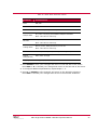
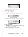
Configuring the Network Settings
To configure the network settings:
1. From the Main Menu, select Comm Settings > Network. The Network Menu
screen appears.
Figure 88: Network Menu Screen
To view the rest of the menu, use the scroll buttons. Figure 89 illustrates the full
Network Menu.
IP
Mask
Gate
PHY
<192.009.200.096>
<255.255.255.000>
<192.009.200.254>
> AUTO
Figure 89: Full Network Menu
2. To edit the network parameters:
Select the parameter you wish to change and press ► to move the cursor to the
right side of the LCD screen.
Press ▼ and ▲ to change the parameter value.
3. To configure additional parameters, press ◄ and repeat step 2.
4. To save your changes, press ENTER. The Comm Settings Menu appears.
5. Press ESC to return to the Main Menu.
38
MX1 Single Channel MPEG 2 Decoder Operation Manual
9
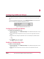
Configuring Additional Setups
The Additional Setups Menu allows you to configure the DVB input bit rate and high
jitter.
To access the Additional Setups Menu, select Additional Setups from the Main Menu.
Figure 90 illustrates the Additional Setups Menu screen.
Figure 90: Additional Setups Menu Screen
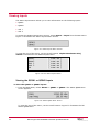
Configuring the DVB Input Bit Rate
To configure the DVB input bit rate:
1. From the Main Menu, select Additional Setups. The Additional Setups Menu screen
appears (Figure 90).
2. Select Input Bit Rate and press ► to move the cursor to the right side of the LCD
screen.
3. Press ▼ and ▲ to change the parameter value. The following are possible values:
54
108
4. Press ENTER to save your changes.
Press ESC to discard your changes.
Enabling or Disabling High Jitter
To enable or disable high jitter:
1. From the Main Menu, select Additional Setups. The Additional Setups Menu screen
appears (Figure 90).
2. Select High Jitter and press ► to move the cursor to the right side of the LCD
screen.
MX1 Single Channel MPEG 2 Decoder Operation Manual
39
3. Press ▼ and ▲ to change the parameter value. The following are possible values:
ON. Select this value to enable high jitter.
OFF. Select this value to disable high jitter.
4. Press ENTER to save your changes.
Press ESC to discard your changes.
40
MX1 Single Channel MPEG 2 Decoder Operation Manual
Glossary
AES/EBU
Digital audio protocol
ASI
Asynchronous Serial Interfaces
BER
Bit Error Rate
BISS
Basic Interoperable Scrambling System
CAM
Conditional Access Module
CA System
Conditional Access system. The CA system provides decryption.
CVBS
Composite Video Bit Stream
DVB
Digital Video Broadcasting
DVR
Digital Video Recorder
FEC
Viterbi Forward Error Correction
Genlock
Signal that synchronizes quad output
ID
Identifier
MCPC
Multi-Channel per Carrier
MCD
Multi-Channel Decryption
MOD
Modulator
NTSC
National TV Standards Committee
PAL
Phase Alternating Line
PASSTHRU
Pass Through
PCR
Program Clock Reference
PID
Program Identification
PIP
Picture in Picture
Quad
Quadrature monitoring
SCPC
Single Channel per Carrier
SDI
Serial Digital Interface
MX1 Single Channel MPEG 2 Decoder Operation Manual
41
SYNCH
Synchronization
SVHS
Super VHS
TS
Transport Stream
VBI
Vertical Blanking Interval
42
MX1 Single Channel MPEG 2 Decoder Operation Manual