1
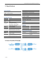
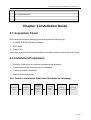
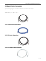
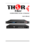
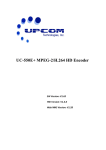
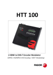
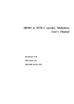
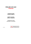
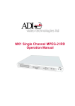
UC-650E+ DVB-S2 Encoder & Modulator User Manual SW Version: 6.11 HW version: 5.8 Web NMS version: 2.00 UC‐650E+ DVB‐S2 Encoder & Modulator User Manual DIRECTORY DIRECTORY .......................................................................................................................................................... 1 CHAPTER 1 INTRODUCTION ................................................................................................................................. 1 1.1 OUTLINE ................................................................................................................................................................. 1 1.2 FEATURES ............................................................................................................................................................... 1 1.3 SPECIFICATIONS ....................................................................................................................................................... 2 1.4 INNER BLOCK DIAGRAM ............................................................................................................................................. 2 1.5 SYSTEM CONNECTION ............................................................................................................................................... 4 1.6 APPEARANCE AND DESCRIPTION .................................................................................................................................. 4 CHAPTER 2 INSTALLATION GUIDE ........................................................................................................................ 5 2.1 ACQUISITION CHECK ................................................................................................................................................. 5 2.2 INSTALLATION PREPARATION ...................................................................................................................................... 5 2.3 WIRE CONNECTION .................................................................................................................................................. 6 2.4 SIGNAL CABLE CONNECTION ....................................................................................................................................... 7 CHAPTER 3 OPERATION ....................................................................................................................................... 8 3.1 LCD MENU TREE ..................................................................................................................................................... 8 3.2 GENERAL SETTING .................................................................................................................................................... 9 CHAPTER 4 WEB NMS MANAGEMENT ................................................................................................................ 19 4.1 LOGIN .................................................................................................................................................................. 19 4.2 PARAMETER CONFIGURATION ................................................................................................................................... 20 CHAPTER 5 TROUBLESHOOTING ............................................................ ERROR! BOOKMARK NOT DEFINED. CHAPTER 6 PACKING LIST ........................................................................ ERROR! BOOKMARK NOT DEFINED. UC‐650E+ DVB‐S2 Encoder & Modulator User Manual About This Manual Intended Audience This manual is intended for end users who will operate and integrate the UC-650 Encoder Modulator. Some chapters require prerequisite knowledge in electronics and broadcasting technology. Disclaimer No part of this document may be reproduced in any form without the written permission of the copyright owner. The contents of this document are subject to revision without notice due to continued progress in methodology, design and manufacturing. UPCOM shall have no liability for any error or damage of any kind resulting from the use of this document. Copy Warning This document includes some confidential information. Its usage is limited to the owners of the product that it is relevant to. It cannot be copied, modified, or translated in another language without prior written authorization from UPCOM. UC‐650E DVB‐S2 Encoder & Modulator User Manual Chapter 1 Introduction 1.1 Outline The UC-650E DVB-S/S2 Encoder/Modulator is an integrated multifunction device. This unit is built around a swappable encoding module (CVBS/SDI/HDMI/YPbPr) for expanded flexibility. One ASI input port is standard. Outputs signals can be sent to ASI or L-Band RF (IF optional) ports simultaneously. This device can accept input signals from a variety of sources thanks to the available encoding module varieties. A user friendly web-based graphical user-interface allows full remote control from any web browser. Broadcasts can be securely encrypted with BISS scrambling. This device is built to broadcasting industry standards making it well suited as a high-quality and low-cost encoding and transmission option for end users. 1.2 Features MPEG2, H.264 video Encoding, MP2, MP2‐AAC, MP4‐AAC Audio Encoding Optional HD SDI Input, pluggable and interchangeable Encoding Modules 1*ASI Input Low Delay achieved (Optional Feature) Support DVB‐S/S2 RF output and ASI output Output Frequency: 950‐2150MHz Support BISS encryption Support for a 10MHz reference clock Support Web NMS and front panel LCD & Keyboard control Firmware Upgrades through web NMS 1 / 32 UC‐650E+ DVB‐S2 Encoder & Modulator User Manual 1.3 Specifications Input Interface DVB-S/S2 Modulation Section SDI (interchangeable with CVBS/YPbPr/S-video DVB-S QPSK: FEC 1/2,2/3,3/4,5/6,7/8 /HDMI… encoding modules) DVB-S2 QPSK: FEC 1/2,3/5,2/3,3/4,4/5,5/6,8/9,9/10 1×ASI input, BNC interface DVB-S2 8PSK FEC 3/5,2/3,3/4,5/6,8/9,9/10 RF output: 950.00-2150.00 MHz, 10Khz step IF output: 50-200MHz Encoding Section Video Encoding MPEG2; MPEG4 AVC/H.264 Input SDI*1 Resolution 1920*1080_60P, 1920*1080_50P, (-for MPEG4 AVC/H.264 only) 1920*1080_60i, 1920*1080_50i, 1280*720_60p, 1280*720_50P 720*480_60i, 720*576_50i Bit rate 1.000~19.500 Mbps Audio Encoding MPEG1 Layer II (MPEG2-AAC, Symbol rate: 0.05-20.0Msps Roll Off: 0.35, 0.25, 0.2 Output level: -10db~-41.5db Output DVB-S/S2 RF output; ASI output (as a mirror of RF) System Local Control LCD + control buttons Remote Control Web-based NMS Language English MPEG4-AAC optional, as per order) Sample rate Bit rate Encoding 48KHz Physical Specification 64kbps, 96kbps, 128kbps, 192kbps, Dimensions 410×460×44mm (W*L*H) 256kbps, 320kbps Temperature 0~45℃(operation), -20~80℃ MPEG4-AAC optional, as per your order) 1.4 Inner Function Principle 2 / 32 (storage) MPEG1 Layer II (MPEG2-AAC, Weight 4kgs Power Supply AC 100-240V 50/60Hz UC‐650E+ DVB‐S2 Encoder & Modulator User Manual 1.5 System Connection Sample 1.6 Appearance and Description Front Panel Illustration 1 3 2 1 LCD Window 2 Indicators 3 Navigation Keys 4 Enter:Confirmation Key 5 Menu: Back-step Key 6 Lock: Locking Key 4 5 6 Rear Panel Illustration 1 2 3 4 5 1 Web NMS (Network Management System) interface 2 SDI Encoding Module 3 ASI input interface 4 ASI output interface 6 7 8 4 / 32 UC‐650E+ DVB‐S2 Encoder & Modulator User Manual 5 10MHz reference clock output interfaces 6 RF output interface 7 Power socket/switch/fuse 8 Ground pole Chapter 2 Installation Guide 2.1 Acquisition Check End users should check packaging contents against the following list: UC-650E DVB-S2 Encoder Modulator SDI Cables Power Cord If any item is missing or mismatched with the list above please contact the local vendor. 2.2 Installation Preparation Carefully checking for any physical damage during shipping. Preparing the correct environment for installation. Preparing network connection. Signal cables connections. 2.2.1 Device’s Installation Flow Chart Illustrated as following: Acquis ition C heck Ins talling D evice C onnecting G rouding Wire and P ower C ord C onnecting S ignal cable S etting P arameter R unning D evice 5 / 32 UC‐650E+ DVB‐S2 Encoder & Modulator User Manual 2.2.2 Environment Requirement Item Requirement Datacenter Ensure a minimum of 1.5M between any two mounted devices. Walls Environment should be no closer than 0.8M. Electricically Isolated & Dust Free Datacenter Floor Volume resistivity of ground anti-static material: 1X10⁷~1X10¹⁰Ω, Grounding current limiting resistance: 1MΩ (Floor bearing should be greater than 450Kg/㎡) Environmental 5~40 (sustainable),0~45 (short term), Temperature Installing air-conditioning is recommended Relative Humidity 20%~80% sustainable Pressure 86~105Kpa Door & Windows Fire Protection 10%~90% short time Installing rubber strips for sealing door-gaps and dual pane glasses for windows is recommended. Fire alarm system and extinguisher is required. Ensure device power, air-conditioning power and lighting power Power circuits are independent of each other. Device power requires DC 12V. Please carefully check all power sources before running. 2.3 Wire’s Connection Connecting the Power Cord User can insert one end into power supply socket, while inserting the other end to main power source. Caution: Before connecting the power cord to UC-650E DVB-S2 Encoder & Modulator user should ensure power switch is set to “OFF”. 6 / 32 UC‐650E+ DVB‐S2 Encoder & Modulator User Manual 2.4 Signal Cables Connection Input and output signal connection cables are illustrated in this chapter. 2.4.1 ASI cable illustration: 2.4.2 Network cable illustration: 2.4.3 SDI cable illustration: 2.4.4 RF output cable illustration: 7 / 32 UC‐650E+ DVB‐S2 Encoder & Modulator User Manual Chapter 3 Operation The UC-650E DVB-S/S2 Encoder/Modulator can be operated using the front panel LCD screen and associated control buttons. This chapter will explain the menu structure: Keyboard Function Description: MENU: Cancel currently entered value, resume previous setting; Return to previous menu. ENTER: Apply setting changes. LEFT/RIGHT: Menu navigation Left/Right. UP/DOWN: Menu navigation Up/Down. LOCK: Locks the screen / cancels the lock state; Saves configuration to memory. 3.1 LCD Menu Tree Switch On Initializing General Status 1 A larm Status E rror C ontent 8 / 32 UC‐650E+ DVB‐S2 Encoder & Modulator User Manual 2 E ncode Setting 3 B ISS Modulate 2.1 Program 1 2.1.1 V ideo Format 2.1.2 V ideo B itrate 2.1.3 A udio Format 2.1.4 A udio B itrate 2.1.5 L ow L atency 3.1 B ISS Mode 3.2 E SW D ata 3.3 SW D ata 3.4 Input ID This function depends on the SD I model type you purchased. 3.5 Select ID 3.6 Parse Program 3.7 Select Program 4 Modulate Setting 4.1 Modulate Mode 4.2 D V B ‐S FE C 4.3 D V B ‐S2 FE C 4.4 Symbol R ate 4.5 R oll Off 4.6 D V B ‐S2 Pilot 4.7 R F Frequency 4.8 R F Out L evel 4.9 R F Output 4.10 Spec Invert 4.11 R F Out Select 4.12 R F 10M C lock 5 Network Setting 5.1 IP A ddress 5.2 Subnet Mask 5.3 Gateway 5.4 MA C A ddress 5.5 R eset Password 5.6 Web Manage Port 6 Saving C onfig Y es or No 7 L oading C onfig 7.1 L oad Saved C FG 7.2 L oad D efault C FG 8 V ersion V ersion Info 3.2 General Setting After successful boot-up the device LCD will display General Status: 9 / 32 UC‐650E+ DVB‐S2 Encoder & Modulator User Manual DVB-S2 Encoder Modulator System Starting... XXX.XXMHz X.XXMbps DVB-S2: Indicates the modulation standard of this device. Encoder Modulator: Device name. XXX.XX MHz: Indicates the current output frequency. X.XX Mbps: Indicates the current encoding bit rate. Pressing the “LOCK” key will allow the user to navigate the Main Menu: ► 1 Alarm Status 3 BISS Modulate ► 5 Network Setting 7 Loading Config 2 Encode Setting 4 Modulate Setting 6 Saving Config 8 Version Please use the UP/DOWN/LEFT/RIGHT navigation buttons to make any desired changes within the Main Menu. 3.2.1 Alarm Status Move the selection cursor to Menu Item 1 and press ENTER. If there are no active alarms, the LCD screen will display the following: Alarm Status No Warning If alarms are present the LCD screen will display relevant messages. For example: Alarm Status TS overflow 10 / 32 UC‐650E+ DVB‐S2 Encoder & Modulator User Manual 3.2.2 Encode Setting This sub-menu will allow the user to configure Video and Audio encoding parameters. ► 2.1.1 Video Format 2.1.2 Video Bitrate 2.1.3 Audio Format 2.1.4 Audio Bitrate ► 2.1.5 Low Latency This function depends on the SDI model type you purchased. The SDI encoding module supports both MPEG2 and H.264 HD/SD video formats. Move the brackets with LEFT/RIGHT keys to specify the intended format and press ENTER to confirm. Video Format [MPEG 2] H.264 Enter sub-menu Video Bit Rate to adjust the desired bit rate by pressing LEFT/RIGHT/UP/DOWN keys and confirm new values by pressing the “LOCK” key. (Bitrate Range: 1-19.5 Mbps) Video Bit Rate 08.000Mbps The supported Audio formats are: MPEG2, MPEG2-AAC and MPEG4-AAC. Move the brackets to specify the desired format and press “ENTER” to confirm: Audio Format [MPEG 2] MPEG2-AAC Audio Bit Rate can be selected within allowed ranges: 64 /96 /128 /192 /256 /320 Kbps Audio Bit Rate ►128 Kbps “Low Latency”: to select a latency mode for the content. Move the selection cursor to specify a mode and press “ENTER” to confirm. 11 / 32 UC‐650E+ DVB‐S2 Encoder & Modulator User Manual ►Normal Mode 1 …..……………………………..…..... NOTE ……..……..…………………………. The different combination of Video Format, Video Bit-rate, Low Latency Mode and the Resolution of signal source will have an impact on the encoding latency. Please refer to the attached Appendix for detailed information. …………………………………………….………………………………………………..…… 3.2.3 BISS Modulation User can navigate to the BISS encryption settings menu by pressing the relevant front panel control buttons. 3.1 BISS Mode 3.3 SW Data 3.2 ESW Data 3.4 Input ID 3.5 Select ID 3.6 Parse Program 3.7 Select Program BISS Mode: UC-650E supports two BISS modes: Mode 1 and Mode E. BISS Mode Mode 1 Mode E NOTE: If Mode 1 is chosen as the BISS mode, “3.3 SW Data” menu will be activated, while “3.2 ESW Data” and “3.4 Input ID” are locked and can’t be operated. Alternatively, if Mode E is chosen as the BISS mode: “3.3 SW Data” menu will be locked and can’t be operated, while “3.2 ESW Data”, “3.4 Input ID” Mode 1 ESW Data X SW Data and “3.5 Select ID” are activated and available. √ Select ID Select ID (Device) Mode E ESW Data √ SW Data X Select ID (Input) X Input ID √ Input ID √ Input ID X X √ ESW Data & Input ID: Under Mode E (with ‘Input’ chosen in “3.5 Select ID”), the BISS 12 / 32 UC‐650E+ DVB‐S2 Encoder & Modulator User Manual scrambler completes scrambling through ESW value and Input ID. User can input the ESW data and ID. ESW Data 1111111111222222 This menu is operable when ‘Input’ is chosen at Input ID menu ‘3.5 Select ID’. 11111111112222 SW Data: Under Mode 1, users can input a 12-digit hexadecimal value. SW Data 0x000000000000 Select ID: Under Mode E, users can choose the ID between Device and Input. Under ‘Input’, ‘Input ID’ will be operable. Select ID Device Input Parse Program: This menu will display the quantity of programs selected from ASI input. Parse Program Get 8 programs NOTES: This menu will be only available if the “4.11 RF Out Select” is set as “ASI”. Select Program: Within this menu, users can decide which programs to encrypt. Press ENTER to and LEFT/RIGHT key to shift “√” (Yes) and “X” (No). Select Program TV-101 [ x ] TV-102 [√] NOTE: When “4.11 RF Out Select” is set as “Encoder”, the program(s) displayed here are sourced from the encoding module; While “4.11 RF Out Select” is set as “ASI”, the program(s) displayed here are from the ASI INPUT. 13 / 32 UC‐650E+ DVB‐S2 Encoder & Modulator User Manual 3.2.4 Modulate Setting Selecting “4 Modulate Setting” in the main menu interface will allow users to set the modulation parameters: 4.1 Modulate Mode 4.3 DVB-S2 FEC 4.2 DVB-S FEC 4.4 Symbol Rate 4.5 Roll Off 4.7 RF Frequency 4.6 DVB-S2 Pilot 4.8 RF Out Level 4.9 RF Output 4.11 RF Out Select 4.10 Spec Invert 4.12 RF 10M Clock Modulate Mode: UC-650E has 3 modulating modes available: DVB-S, DVB-S2-QPSK and DVB-S2-8PSK. Modulate Mode [DVB-S] DVB-S2-QPSK DVB-S2-8PSK DVB-S FEC (Forward Error Correction): Users can set their desired FEC ratios from within the allowed value range (1/2, 2/3, 3/4, 5/6 and 7/8). NOTE: This menu will be available if DVB-S is selected as the modulating mode within Menu 4.1. DVB-S FEC 1/2 2/3 3/4 DVB-S2 FEC (Forward Error Correction): User can select one DVB-S2 FEC ratios from options provided by pressing RIGHT/LEFT key. NOTE: This menu will be available if DVB-S2-QPSK or DVB-S2-8PSK is selected as the modulation mode within menu 4.1. Modulating Mode FEC Options DVB-S2-QPSK QPSK1/2, QPSK3/5, QPSK3/4, QPSK4/5, QPSK5/6, QPSK8/9, QPSK9/10 DVB-S2-8PSK 8PSK3/5, QPSK2/3, 8PSK3/4, 8PSK5/6, 8PSK8/9, 8PSK9/10 14 / 32 UC‐650E+ DVB‐S2 Encoder & Modulator User Manual DVB-S2 FEC [QPSK1/2] QPSK3/5 QPSK3/4 Symbol Rate: User can navigate to this menu to modify symbol rate (allowed range: 0.050~20.000Mbps) by pressing UP/DOWN/LEFT/RIGHT keys confirm by pressing “LOCK” key. Symbol Rate 17.500 Mbps Roll Off: User can enter this menu to select roll-off factor. Different selections will affect maximum input bit-rate. Roll OFF DVB-S2 Pilot: 0.35 0.25 0.2 The DVB-S2 Pilot can be switched on or off through this menu. NOTE: DVB-S2-QPSK or DVB-S2-8PSK must be selected as the modulation mode within menu 4.1 to enable this option. DVB-S2 Pilot On Off RF Frequency: The RF output frequency range is from 950 to 2150MHz with 1K stepping. Users then can press LEFT/RIGHT/UP/DOWN button to adjust the frequency and confirm by pressing ENTER button. RF frequency 2000.000 MHz RF Output Level: The RF attenuation range is from -10db~-41.5db. After entering this setting submenu, user can shift UP/DOWN/LEFT/RIGHT key to set the output level and press ENTER to confirm. RF Out Level -10.0db 15 / 32 UC‐650E+ DVB‐S2 Encoder & Modulator User Manual RF Output: The RF output mode can be selected within this menu: The available modes are: single tone, modulation, and OFF. RF Out Single tone modulation off Spec Invert: User can switch the Spectrum Invert mode between Normal and Inverted under this menu. Spec Invert Normal Invert RF Out Select: This sub-menu will allow the user to select the output program source. The source can be set to the encoding module or ASI input. It can only modulate one source at any one time. RF Output Encoder ASI RF 10M Clock: The RF 10M Clock (reference clock) can be switched on or off through this menu. RF 10M Clock OFF ON 3.2.5 Network Setting User can press “ENTER” key to navigate into the network setting and modify the parameters under its corresponding submenus. 5.1 IP Address 5.3 Gateway 5.2 Subnet Mask 5.4 MAC Address 16 / 32 UC‐650E+ DVB‐S2 Encoder & Modulator User Manual 5.5 Reset Password 5.6 Web Manage Port Press “UP/DOWN” to choose one item and “ENTER” & “LEFT/RIGHT” to set the desired parameters. IP Address 192.168.000.136 Subnet Mask 255.255.255.000 Gateway 192.168.000.001 MAC Address ffffffffffffffffffffff Reset Password? Yes NO Web Manage Port 00080 NOTE: The default MAC address is unique. 3.2.6 Saving Configuration User can choose to save the currently configured parameters to memory by pressing ENTER key. The system displays following page: Save Configuration? Yes NO Saving, please wait: Erasing……. 17 / 32 UC‐650E+ DVB‐S2 Encoder & Modulator User Manual 3.2.7 Loading Configuration This sub-menu will allow the user to load previously saved configurations or revert the device to factory settings. 7.1 Load Saved CFG 7.2 Default CFG Loading, please wait: >>>>>>>>>>>>>>>> 3.2.8 Version User can check the device’s hardware and software version within this submenu: Encoder Modulator SW x.xx HW x.xx 18 / 32 UC‐650E+ DVB‐S2 Encoder & Modulator User Manual Chapter 4 Web NMS Management The UC-650E DVB-S2 Encoder Modulator adopts a web-based user interface. Before operating, user should ensure that the computer’s IP address is different from the UC-650E’s IP address; otherwise, it will cause an IP address conflict. 4.1 Login The default IP of this device is 192.168.0.136. User can change the IP from the front panel of the device. Connect the PC and the device with an Ethernet cable, and use ping command to confirm the devices can communicate. For example, if the PC IP address is 192.168.99.252, user could change the Device IP to 192.168.99.196 to prevent conflicts. Enter the device IP in the browser address bar and press Enter. Figure 1 Input the user name and password (The default Username and Password is ‘admin’) and then click ‘Login’ to enter the welcome interface. 19 / 32 UC‐650E+ DVB‐S2 Encoder & Modulator User Manual 4.2 Parameter Configuration Summary→Status Once logged in users will be given an overview of the device status. Devices Name System information and general working status User can click any item here to enter the corresponding interface to check information or set the parameters. Figure 2 Parameters → Encoder Clicking ‘Encoder’ in the left hand column will display program encoding information. Users can configure encoding AV parameters in this interface. 20 / 32 UC‐650E+ DVB‐S2 Encoder & Modulator User Manual 2 encoding format selection Audio/Video editing area Monitoring area Figure 3 Will pop-up additional parameter information. Click this button to apply the default setting of Encoder. Click this button to apply the modified parameters. Parameters → Modulator User can click ‘Modulator’ in the left-hand column to navigate into the Modulation interface. More details are included in chapter 3.2.4 in this manual. 21 / 32 UC‐650E+ DVB‐S2 Encoder & Modulator User Manual Figure 4 DVB-S Modulation mode DVB-S2 QPSK Device supports DVB-S, DVB-S2 QPSK and DVB-S2 8PSK three modes. DVB-S2 8PSK DVB-S FEC 1/2, 2/3, 3/4, 5/6, 7/8 1/2, 3/5, 2/3, DVB-S2 FEC 3/4, 5/6, 8/9, 9/10; Symbol rate Roll off under DVB-S mode, it supports FEC 1/2, 2/3, 3/4, 5/6, 7/8 under DVB-S2 QPSK mode, it supports FEC 1/2, 3/5, 2/3, 3/4, 4/5, 5/6, 8/9, 9/10; Under DVB-S2 8PSK mode, it supports FEC 3/5, 2/3, 3/4, 5/6, 8/9, 9/10 Symbol Rate range is 0.050-20.000Msps 0.35/0.25/0.2 selecting DVB-S2 pilot DVB-S2 pilot ON/OFF selecting RF requency RF frequency is ranged from 950.00-2150.00MHz RF out level RF output level ranges from -10db~-41.5db 22 / 32 UC‐650E+ DVB‐S2 Encoder & Modulator User Manual RF Mode RF 10MHz Clock Spec Invert The RF out modes are: single tone, modulation, and off. Enable or Disable 10MHZ Reference Inverts the spectrum. . Encoder: to output the programs from encoding module via RF Out RF&ASI; ASI: to output the programs from ASI in via RF&ASI; Parameters → BISS Config: Click BISS Config in the left hand column to navigate into the BISS interface to scramble the programs sourced from encoding module or ASI port. Figure 5 The BISS scrambling function application needs to be matched with BISS descrambler. The BISS scrambling supports two modes: “Mode 1” and “Mode E”. Users can select one of the two modes in the drop down list. 23 / 32 UC‐650E+ DVB‐S2 Encoder & Modulator User Manual Mode 1 Under Mode 1, the BISS scrambler applies scrambling by a fixed Control Word (CW) derived from a clear SW (Session Word). In Mode 1, a fixed 12-digit SW is inserted in the scrambler. The 64-bit CW is derived from the SW according to DVB-CAS specification. Users can select Mode 1 in the drop-down menu, and then input the 12-digit SW Data (in hex). The downside device descrambler key equals SW Data on the BISS scrambler side. Mode E Under Mode E, the BISS scrambler completes scrambling through ESW Data and Input ID (Input ID is operable when ‘Input’ is chosen under ‘Select ID’.). The ESW data equals Descrambler key on the downside device side, while the input ID equals SK on IRD side. The select ID has two options: Device and Input. If Users choose Device, the Burned Key on IRD side needs to be selected when descrambling, while if users choose Input and set Input ID, on IRD side, users do not need to select Burned Key but to input SK as per Input ID. Program Select and Modification: User then can click ‘Parse Prg’ to view the input programs and modify the program names as needed. If the user need to scramble the programs, mark the corresponding boxes in front of the programs with √and click Set to activate the setting. Note: When “RF Out” in ‘Modulator’ page is selected as “Encoder”, the program(s) displayed here is from the encoding module; while “RF Out” is selected as “ASI”, the program(s) displayed here is from the ASI IN. 24 / 32 UC‐650E+ DVB‐S2 Encoder & Modulator User Manual Parameters → Network: Click ‘Network’, it will display the screen as below. It displays the network information of the device where to change the device’s network configuration if needed. Figure 6 System → Save/Restore: Click ‘Save/Restore’ from the menu and it will display the screen as below where users can save the configuration permanently to the device. Click ‘Save Configuration’ button to store the data permanently to the device memory. By using ‘Restore Configuration’ users can restore the latest saving configuration to the device. By using ‘Factory Set,’ user can set the default factory setting. 25 / 32 UC‐650E+ DVB‐S2 Encoder & Modulator User Manual Figure 7 System → Backup/Load Click ‘Backup/Load’ from the menu, it will display the screen as below. Browse Button Figure 8 26 / 32 UC‐650E+ DVB‐S2 Encoder & Modulator User Manual System → Password: User can change the password in this interface by first entering current username and password and then entering new username and password to change. After inputting the parameters, click ‘Apply’ to save the configuration. Figure 9 System → Firmware Click ‘Firmware’ from the menu and it will display the screen as below. Here we can update the device by using the update file. Click ‘Browse’ to find the path of the device update file for this device then click on ‘Update’ to update the device. After updating the device we need to restart the device by using Reboot option. 27 / 32 UC‐650E+ DVB‐S2 Encoder & Modulator User Manual Figure 10 System → Reboot Clicking ‘Reboot’ from the left hand menu will display the following interface. When users click ‘Reboot’ button, it will restart the device automatically. Figure 11 28 / 32 UC‐650E+ DVB‐S2 Encoder & Modulator User Manual Chapter 5 Troubleshooting UPCOM Technologies’ ISO9001 quality assurance system has been approved by the CQC Organization to guarantee all products’ quality and reliability. UPCOM products must pass testing and inspection before leaving the factory. The testing and inspection process covers all the Optical, Electronic, and Mechanical criteria. To prevent potential hazard, please strictly follow all operation instructions. Upcom Technical support can be contacted by e-mailing [email protected] or calling 1-408-329-4158. Preventative Measure Installing and operating the device in temperatures between 0-45 °C. Ensuring proper cooling airflow for the device. Carefully check the input AC for the proper power supply working range. Check all signal cables have been properly connected. Allow a 10-second interval between alternating power ON\OFF states. Unplug the power cord if: Damaged power cord or socket. Any accidental liquid spillage on device. Any suspicion of short circuits. Physical damage. Long-term idle periods are planned. Performing any needed maintenance. 29 / 32 UC‐650E+ DVB‐S2 Encoder & Modulator User Manual APPENDIX INTERNAL TEST REPORT OF DELAY The values of average delay cover the progress from Encoding end to Decoding end. Encoding Details Decoding Terminal Single Source Interface Bit Rate Resolution Latency Mode Mode 1 1080i@50 Mode 2 DVB-T HD STB Mode 1 HDMI 14M 720p@50 Mode 2 Mode 1 576i@50 Mode 2 Mode 1 1080i@50 Mode 2 DVB-T HD STB Mode 1 SDI 14M 720p@50 Mode 2 Mode 1 576i@50 Mode 2 Encoding Type Average Latency (ms) mpeg2 343 H.264 375 mpeg2 460 H.264 513 mpeg2 243 H.264 400 mpeg2 405 H.264 408 mpeg2 418 H.264 518 mpeg2 520 H.264 593 mpeg2 230 H.264 310 mpeg2 400 H.264 440 mpeg2 220 H.264 350 mpeg2 300 H.264 400 mpeg2 400 H.264 500 mpeg2 460 H.264 570 30 / 32