1
PRO.FORMI
Model No. 831,297773
Serial No,
Rnd the sedal number in the location
shown below. Wdte the serial number
In the space above for reference.
_,
isedal Number
ecal
HELPLINE!
1-800-736-6879
USER'S MANUAL
SEARS_ ROEBUCK AND CO., HOFFMAN
ESTATES, IL 60179
TABLE OF CONTENTS
IMPORTANT PRECAUTIONS
.................................................................
BEFORE YOU BEGIN .......................................................................
ASSEMBLY ".-.; • --, o*
• ................
,,
_
°°oo°.oo.o*.°....o
ooo...,oo,
ooo°o
OPERATION AND ADJUSTMENT
.............................................................
HOW TO FOLD AND MOVE THE TREADMILL
..................................................
TROUBLE-SHOOTING
..........
, ........
_ .................................................
CONDITIONING GUIDELINES
...............................................................
PART LIST..-...............................................
--------'---•
----ORDERING REPLACEMENT PARTS .......................
_..........................
FULL 90-DAY WARRANTY .........................................................
Note: An EXPLODED
IMPORTANT
2
DRAWING
is attached in the center of this manual.
PRECAUTIONS
.....
oo
• .-..
....
2
4
°.oo..°o.
5
7
11
12
14
.. .
15
Back Cover
Back Cover
The decals shown have been placed on
your treadmill. If a decal is missing, or if
it is not legible, please call our toll-free
HELPLINE to order a free replacement
decal. Apply the decal in the location
shown.
• Never allow children on
or around treadmill.
\
• Storage latch must be
fully engaged before
treadmill is moved or
stored.
• Incline must be set at
lowest level before folding
treadmill into storage
KEEPHANDSANDFEETAWAY
FROMTHISAREAWHILETHE
TREADMILLIS IN OPERATION.
3
BEFORE
YOU BEGIN
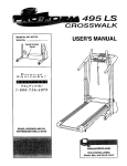
Thank you for selecting the new PROFORM = 595LE
treadmill The 595LE treadmill combines advanced
technology wlthlrmovatlve design to let you.enjoy an
excellent form of cardiovascular exercise in the convenience and pdvacy of your home. And when you're not
exercising, the unique 595LE can be folded up, requirIng less than half the floor space of other treadmiUs.
Monday through Saturday, 7 a.m. unhl 7 p.m. Central
Time (excluding holidays). To help us assist you,
please note the product medal number and serial number before ceiling. The model number of the treadmill
is 831.297773. The sedal number can be found on a
decal attached to the treadrniU (sea the front cover of
this manual for the location).
For your benefit, read this manual carefully before
using the treadmill. If you have addiUonal questions,
please call our toll-free HELPLINE at 1-800736-6879,
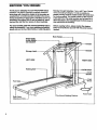
Before reading further, please review the drawing
below and familiarize yourself with the parts that are
labeled.
Book Holder
Water Bottle
Holder (Boffie
not Induded_
,Handrail
Storage latch-
LEFT SIDE
RIGHT sIDE
Walking Belt
Circuit
Breaker
Front
Wheel
Foot Rails
' Cord
_gPlatform
r Roller
Adjustment Bolts
4
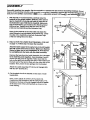
ASSEMBLY
Assembly requires two people. Set the treadmill in a cleared area and remove all pecking materials. Do not
dispose of the packing matedals until assembly is completed. Assembly requires the included alle_rench.._
and your own phillips screwdriver (]_3
=_-_ , adjustable wrench _
and sclssore _
1. With the help of a second person, earefully raise the
treadmill to the updght position. While the other person
tips the treadmill to one slde and holds it, insert one of
the Extension Legs (103) into the treadmill Make sure
that the Extension Leg Is turned so the Warning Decal
(20) Is on top. Tighten two of the four Short Screws
(101) Into the treadmill and the Extension Leg.
Next, tip the treadmill to the other side and attach the
other Extension Leg (not shown) in the same way. Lower
the side of the treadmill so that both Extension Legs
(103) are resting fiat on the floor.
2. Refer to HOWTO
LOWER THE TREADMILL
FOR USE
2
on page 11, Follow step 2 to lower the treadmill.
Attachthe latchsupporttothe centerholein the left Updght
(82) witha 3/4" Screw (81) as shown. Make sure that the
Screw is tight, but do not overtlghten it; if the Screw
is overtightened, the latch will not slide smoothly.
Remove the tape from the Latch Assembly (77). Be careful to hold the parts together. Inset drawings A and B
shows how the parts fits together. Make sure that the
tabs on the latch are touching one side of the bracket and
the back end of the latch is flush with the other side of the
bracket. Then, insert the two springs into the bracket.
z
I
I
Attach the Latch Assembly (77) to the left Upright (82)
with two 3/4" Screws (81).
3. Cut the plastic tie off the bracket on the base of each
Upright (82).
Next, cut the plastic tie off the Left Handrail (74).
Position the Left Handrail on the left Upright (82). The
bracket on the base of the left Upright should be inside
of the lower end of the Left Handrail, as shown in the
inset drawing.
Bif°T
S
Spring
Latch
Support
Flush,,,_
_.
Spring-
_
Plastic 7
Tie
82 1
Plastic
Tie
5
4. While a second persoo holds theRight Handrail (85) and
theCo ote Base ( ..ear
the
UpdOht(82),cutthe
4
Indicated plas_ic'tios off the Right Handmll. Do not cut
the other plastic tie off the Right Handrail. Next, cut
the plastic tie off the Upright Wire Harness (34) in the
dght Upright (&_), Do not drop the Up.right Wire
Harness into the right Upright.
Do not
Refer to the Inset drawing. Connect the Upright Wire
Hamess (34) to the Console Wire Harness (48). The
latch on the Console Wire Harness should snap onto the
Updght Wire Harness. If the Wire Harnesses do not fit
together easily, turn them; do not force the Wire
Hamasses together. Next, connect the dght pulse wire
(with the 'l:f'.tag), the left pulse wire, and the ground wire
to the corresponding connectors on the Console Wire
Harness (48); make sure that the wires with tags are
connected to each other.
5: Nots that thel;e is still a plastic tie in the Right
: Handrail (85); do not remove this plastic tie.
Ground
85
-Cut Plastic Tie
5
7
:Position the Right Han_:lrait(85) on the right Updght (82)
as shown. The bracket on the bass of the dght Upright
should be Inside of the lower end of the dght Handrail, as
shown In the Inset drawing.
•
Donot
Remove
this
Tie
36
While holding the Console Base (87) near the Right
Handrail (85), feed the Console Wire Hamess (48) into
the Right Handrail. Next, place the Console Base on the
Handrails (74, 85). Insert any remaining Console Wire
Hamess Into the Right Handrail.
, Thread two Handrail Bolts (78) with Handrail Washers
(36) Into the Left Handrail (74) and the left Updght (82) as
shown. Do not tighten the Handrail Bolts yet. Next,
thread two Handrall Bolts (78) with Handrail Washers
(36) into the Right Handrail (85) and the dght Upright
(82). Do not tighten the Handrail Bolts yet. Be careful
to avoid damaging the Console Wire Harness (48).
6. Attach the Console Base (87) to the Left and Right
Handrails (74, 85) with four Long Screws (114).
6
87___=__
Refer to assembly step 5. Tighten the four Handrail
Bolts (78) used in assembly step 5.
Press two Small Upright Plugs (79) into the holes near
the upper ends of the Uprights (82).
7. Remove the backing from the Adhesive Clip (99). Press
the Adhesive Clip onto the base of the dght Updght (82)
as shown. Press the Allen Wrench (100) into the
Adhesive Clip.
6
8. Make sure that all parts are tightened before you
use the treadmill. To protect the floor or carpet, place
a mat under the treadmill
\\ II
99
100
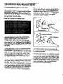
OPERATION AND ADJUSTMENT
THE PERFORMANT
LUBE
TM
WALKING
BELT
Your treadmill features a walking belt coated with
PERFORMANT LUBE TM, a hlgh-pedormance lubricant.
IMPORTANT: Never apply ell|cone spray or other
substances to the walldng belt or the walking plat.
form. Such substances will deteriorate the walking
belt and cause excessive wear.
This product Is for use on a nominal 120-volt circuit,
and has a grounding plug that looks like the plug illustrated in drawing I below. A temporary adapter that
looks like the adapter illustrated in drawing 2 may be
used to connect the surge suppressor to a 2-pele
receptacle as shown in drawing 2 if a properly
grounded outlet is not available.
HOW TO PLUG IN THE POWER CORD
i
_//_l-J_Grounded
_. 1 _Surge
Outlet Box
Suppressor
%
round,ng
p,n
Grounded Outlet
(_roundlng Plug"_
2
_Gr°U/ll
pj i =
Your treadmlU, like any other type of sophisticated
electronic equipment, can be sedouely damaged by
sudden voltage changes In your homo's power.
Voltage surges, spikes, and noise Interference can
result from weather conditions or from other appliances
being turned on or off. To decrease the possibility of
your treadmill being damaged, always use a surge
suppressor with your treadmill (see drawing I at
the right).
Surge suppressors are sold at most hardware stores
and department stores. Use only a single-outlet surge
suppressor that Is UL 1449 listed as a transient voltage
surge suppressor (TVSS). The surge suppressor must
have a UL suppressed voltage rating of 400 volts or
less and a minimum surge dissipation of 450 joules.
The surge suppressor must be electrically rated for
120 volts AC and 15 amps.
This product must be grounded. If it should malfunction or break down, grounding provides a path of least
resistance for electric current to reduce the risk of electric shock. This product is equipped with a cord having
an equipment-grounding conductor and a grounding
plug. Plug the power cord into a surge suppressor,
and p|ug the surge suppressor into an appropriate
outlet that is properly Installed and grounded in
accordance with all local codes and ordinances.
A._da; Outlet: °x
o.
. .
-
_urge _uppressor
Metal Screw
The temporary adapter should be used only until a
propedy grounded outlet (drawing 1) can be |nstailed
by a qualified electrician.
The green-colored rigid ear, lug, or the like extending}
from the adapter must be connected to a permanent
ground such as a prepedy grounded outlet box cover.
Whenever the adapter is used it must be held in place
by a metal screw. Some 2-pole receptacle outlet box
covers are not grounded. Contact a qualified electrician to determine if the outlet box cover is
grounded before using an adapter.
7
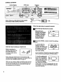
CONSOLE DIAGRAM
Incline Display
LED Track
on the face of the console, =:emove IL
Follow the
B
stepsbelow to operate the console.
Insert the key fully intothe
console.
When the key is
Inserted, one Indicator
will light In the Incline
display, one Indicator
will light In the LED
track, and the four
displays will light.
B
Press
belt. the SPEED A button to start the walking
A moment after the
SPEED Z_button is
STEP-BY-STEP
CONSOLE
Before operating the
console, make sure that
the on/off switch near
the power cord is in the
on position.
OPERATION
OnJ
Position
Next, make sure that the key is removed from the
console and then plug in the power cord (see HOW TO
PLUG IN THE POWER CORD on page 7).
When you are ready to begin exercising, step onto the
foot rails of the treadmill. Find the clip attached to the
key (see the drawing above), and slide the clip onto
the waistband of your clothing.
I
tf
i=
pressed, the walking belt
will begin to move. Hold
the handrails and carefully begin walking.
As you exercise, change the speed of the waiking
belt as desired by pressing the SPEED buttons.
To stop the walking belt,
press the STOP/RESET
button. The TIME/PACE
display will begin to flash.
To restart the walking
belt, press the SPEED A
button again. To stop the walking belt and reset
the displays, press the STOP/RESET button for
about two seconds.
=
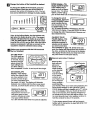
Change the incline of the treadmill as desired.
To change the Iricllne of the treadmill, press the
Incline buttons. Each time one of the buttons is
pressed, the incline will change by 0.5%, The buttons can be held down to change the Incline mpldly.
0
t
=
....
7
=
o
°
i
I
I
SPEED
I I
=MPH" or "KPH" will appear to show which unit of measurement is selected.
To change the unit of
measurement, hold down
the STOP/RESET button
while inserting the key
into the console. An =E,"
for english miles, or an
=M," for metric kilometers, will appear in the DISTANCE/LAPS display. Press the SPEED Z_button
to change the unit of measurement. Remove and .
then relnsert the key.
Note: In the incline display, the first indicator will
light when the Ihcline is set at 1.5%. The second
indicator will light when the incline is set at 2% or
2.5%, the third indicator will light when the incline
Is set at 3% or 3.5%, and so forth. After the incline
buttons are pressed, it will take a moment for the
treadmill to reach the selected incline setting.
L_
display shovethe speed
of the walking belt, in
miles per hour or kilometers per hour. The letters
Follow your progress with the LED track and
the four displays.
The LED Track-The LED track represents a distance
of 114 mile. As you
exemise, the indicators around the
track will light one
at a time until you
have completed 114 mile. A new lap will then begin.
DISTANCE/LAPS
disptay--This display
shows the distance that
you have walked or run
and the number of laps
you have completed (one
lap equals 1/4 mile). The display will alternate
between one number and the other every seven
seconds, as shown by the arrows in the display.
TIME/PACE display-This display shows the
elapsed time and your current pace (pace is meaTIME
PACE
sured in minutes per mi/e).
Your pace will be shown
for a few seconds each time the speed is adjusted.
IB:'-IB !
CALS/FAT CALS/
PULSE display--This
display shows the approximate numbem of
calories and fat calories
I
I_I
L ,2211
PULSE
CALS.
I
FATCALS.
you have burned (see
FAT BURNING on page 14). Every seven seconds, the display will change from one number to
the other, as shown by the arrows In the display.
This display will also show your heart rate when
the pulse sensor is used (see step 5).
[]Measure
your pulse, If desired.
Stand on the
foot rails and
place your
hands on the
metal contacts
on the handrail.
Metal Contacts
Your palms
must be resting
PULSE
on the upper
contacts, and
your fingers must
CALS.
FAT CALS.
be touching the
lower contacts-avoid moving
your hands. When your heart rate is detected, the
heart-shaped indicator in the CALS/FAT CALS/
PULSE display will flash steadily and a "P" will appear in the display. Hold your thumb at this level.
After a few seconds, three dashes will appear in
the display and your heart rate will be shown. For
the most accurate heart rate reading, continue to
hold the contacts for about 15 seconds.
Try the sensor several times until you become
familiar with it. Remember to stand still while meao
sudng your pulse.
9
_When
you are 11nished, remove the key.
Step'ont_ the foot c_lfS
and remove the key
from the console. Keep
the key in e eee_e
place.
In addition, move the on/off switch to the off position. (See the drawing near the bottom of page 8.)
THE lNFORMA'ZIOH MODE
To e_cess the Information mode, holddown the STOP/
RESET lo_tton while Inserting the key Into the console.
An "E," for eng,sh miles, or an
"M," for metric Idlometers, will
appear In the DISTANCFJ
LAPS display. Press the
SPEED A button to change
the unit of n'masummant.
show the totat number of
hours the treadmill has been
used.
11ME
The SPEED display will show
the total number of miles that
the walking belt has rnoved.
To exit the Intofmatlon mode, remove the key |rom the
console.,
10
HOW TO FOLD AND MOVE THE TREADM!LL
HOW TO FOLD THE TREADMILL
FOR STORAGE
Before folding the treadmill, adjust the Incline to the
lowest position. If this is not done, the treadmill may be
permanently damaged. Next, unplug the power cord.
CAUTION: You must be able to safely lift 45 pounds (20
kg) in order to raise, lower, or move the treadmill.
1. Hold the treadmill with your hands in the locations shown
at the flghL CAUTION: To decrease the possibUity of inJury, bend your legs end keep your back atraighL As
you raise the treadml!l, make sure to lift with your legs
rather than your back. Raise the treadmill about halfway
to the vertical position.
2. Move your right .hand td the position shown and hold the
treadmil! firmly. Using your left thumb, slide the storage
latch to the !eft and hold IL Raise the treadmill until the
storage latch closes over the catch. Make sure that the
storage latch is fully closed over the latch catch.
2
Open
To protect the floor or carpet from damage, place a
mat under the treadmlU. Keep the treadmill out of
direct sunlight. Do not leave the treadmill In the storage position In temperatures above 85 ° Fahrenheit.
Closed
HOW TO MOVE THE TREADMILL
3
Before moving the treadmill, convert the treadmill to the storage position as descdbed above. Make sure that the storage latch is closed fully over the catch.
1. Hold the handrails as shown and place one foot against a
wheel. Do not hold or push on the book holder or the
book holder may be damaged.
2. Tilt the treadmill back until it rolls freely on the front wheels.
Carefully move the treadmill to the desired location. Never
move the treadmill without tipping it back. To reduce
the risk of injury, use extreme caution while moving
the treadmill. Do not attempt to move the treadmill
over an uneven surface.
3. Place one foot on the base, and carefully lower the treadmill until it is resting In the storage position.
HOW TO LOWER THE TREADMILL
/
Base
_
"_" Front Wheels
FOR USE
1. Refer to drawing 2 above. Hold the upper end of the treadmill with your dght hand as shown. Using your left
thumb, slide the storage latch to the left and hold it. Pivot the treadmill down until the frame is past the storage
latch.
2. Refer to drawing 1 above. Hold the treadmill firmly with both hands, and lower the treadmill to the floor.
CAUTION: To decrease the possibility of Injury, bend your legs and keep your back straight.
11
TROUBLE-SHOOTING
Most treadmill problems can be solved by following the simple steps below. Rnd the symptom that
applies, end follow the steps listed. If further assistance is needed, cail our toll-free HELPLINE at
1-800-736-'687g, _day
through Satut,day, 7 a.m. until 7 p.m. Central Time (excluding holidays).
PROBLEM:
THE POWER DOES NOTTURN
ON
SOLUTION:
a. Make sure that the power o_d is plugged into a surge suppressor, and that the surge suppressor
is plugged into a properly grounded outlet (see page 7). Use only a single-outlet surge suppressor
that is UL 1449 listed as a transient voltage surge suppresser ('I'VSS). The surge suppressor
must have a UL suppressed voltage rating of 400 volts or less and a minimum surge dissipation
of 450 joules. The surge suppressor must be electrk_lly rated for 120 volts AC and 15 amp6.
b, After the power cord has been plugged in, make sure that the key is fully inserted into the console. See step I on page 8.
c: Check the circuit breaker located on the treadmill
near the power cord. If the swttch protrudes as
=shown, the circuit breaker has tdpped. To reset the
cimuti breaker, wait for five rnlnutas and then press
the switch back in.
d. Check the on/off switch located on the treadmlll
near the power cord. The sw_ch must be In the on
position.
¢
Tdpped
Reset
d
Position
PROBLEM: THE POWER TURNS OFF DURING USE
SOLUTION:
a. Check the ctrcuit breaker located on the treadmill frame near the power cord (see 1. c. above). If
the cimuit breaker has tdpped, wait for f'Ne minutes and then press the switch back in.
b. Make sure that the power cord Is plugged in.
c. Remove the key from the console. Re|nsert the key fully into the console. See step I on page 8.
d. Make sure that the on/off switch Is In the on position.
e. If the treadmill still will not run, please call our toll-free HELPLINE.
PROBLEM: THE DISPLAYS OF THE CONSOLE DO NOT FUNCTION
SOLUTION:
a. Unplug the power cord. Remove the s_ews from
the hood. Carefully remove the hood. Locate the Reed
Switch (21) and the Magnet (43) on the left side of the
Pulley (42). Turn the Pulley until the Magnet Is aligned
with the Reed Switch. Make sure that the gap between the Magnet and the Reed Switch is about
1/8". If necessary, loosen the Reed Switch Screw (76)
and move the Reed Switch slightly. Retighten the
Screw. Re-attach the hood, and run the treadmill for a
few minutes to check for a correct speed reading.
12
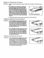
PROPERLY
PROBLEM:
The walking belt slows when walked on
soLUTION:
a. Use only a UL41sted surge protector, rated at 15 amps, with a 14-gauge cord of five feet or less In
length.
b. If the walking belt Is overtightened, treadmill performance rna.y decrease and the walking belt may be
permanently damaged. Remove the key and UNPLUG THE POWER CORD. Using the allen wrench,
tum both rear roller adjustment bolts countercJockwise, 114 of a turn. When the walking belt is propedy
tightened, you should be able to lift each slde of the
walking belt 3 to 4 Inches off the walking platform. Be
careful to keep the walking belt .centered. Plug in the
power cord, Insert the key and run the treadmill for a
few minutes. Repeat until the walking belt is prepedy
tightened.
Rear Roller Adjustment Bolts
c. If the walking belt still slows when walked on, please call our toll-free HELPLINE.
PROBLEM: The walking belt is off-center when walked on
SOLUTION:
a. If the walking belt has shifted to the left, first remove
the key and UNPLUG THE POWER CORD. Using
the ellen wrench, tum the left rear roller adjustment
bolt cleckwise, and the fight bolt countereledoNIse,
114 of a turn each. Be careful not to overtighten the
walking belt. Plug In the power cord, Insert the key
and run the treadmill for a few minutes. Repeat until
the walking belt Is centered.
b. If the walking belt has shifted to the fight, first remove
the key and UNPLUG THE POWER CORD. Using
the allen wrench, turn the left rear roller adjustment
bolt counterclockwise, and the fight bolt cled0_se,
1/4 of a turn each. Be careful not to overtighten the
walking belt. Plug in the power cord, insert the key
and run the treadmill for a few m|nutes. Repeat until
the walking belt Is centered.
PROBLEM: The welking
SOLUTION:
belt slips when walked on
a. If the walking belt slips when walked on, first remove
the key and UNPLUG THE POWER CORD. Using
the allen wrench, turn both rear roller adjustment
bolts clockwise, 1/4 of a turn. When the walking belt
is correctly tightened, you should be able to lift each
side of the walking belt 3 to 4 inches off the walking
platform. Be careful to keep the walking belt centered.
Plug in the power cord, insert the key and carefully
walk on the treadmill for a few minutes. Repeat until
the walking belt is properly tightened.
a
1:
CONDITIONING GUIDELINES
uses easily accessible carbohydrate calories for energy. Ordy after the first few minutes does your body
begin to use stored fat ca/or/as for energy. If your goal
is to bum fat, adjust the speed and incline of the treedmill until your heart rate is near the lowest number in
your training zone.
For maximum fat bumlng, adjust the speed and Incline
of the treadmlil until your heart rate is near the middle
number In*your training zone.
Aerobic
The following guidelines will help you to plan your exerclse program. Remember---these are general guidelines only. For more detailed exercise infom-,atton, obtain a reputable book or nonsult your physician.
EXERCISE INTENSITY
Exercise
If your goal is to strengthen your cardiovascular system, your exercise must be =aerobic." Aerobic exercise
is activity that requires large amounts of oxygen for
prolonged peduds of time. Thls Increases the demand
on the heart to pump blood to the muscles, and on the
lungs to oxygenate the blood. For aerobic exercise,
adjust the speed and Incline of the treadmill until your
heart rate is near the hlghest number in your training
:ZOrn.
Whether your goal is to bum fat or to strengthen your
cardiovascular system, the key to achlevlng the
desired results Is to exercise with the proper Intensity.
The proper Intensity level can be found by using your
heart rate as a guide. The chart below shows recommended heart rates forf_ bumlr_g and aerobt_ exercise.
To find the proper heart rate for you, first find your age
near the bottom of the chart (ages are rounded off to
the nearest ten years). Next, find the three numbers
above your age. The three numbers define your "trainIng zone." The tower two numbers are recommended
heart rates for fat burning; the higher number is the
recommended heart rate for aerobic exercise.
To measure your heart rate during exemise, use the
pulse sensor. If your heart rate is too high or too low,
adjust the speed and incline of the treadmill.
Fat Burning
To bum fat effectively, you must exercise at a relatively
low intensity level for a sustained period of time.
During the first few minutes of exercise, your body
14
WORKOUT GUIDELINES
Each workout should Include the following three pads:
A Warm-up--Start each workout with 5 to 10 minutes
of stretching and light exercise. A proper warm-up Increases your body temperature, heart rate and circulation in preparation for exercise.
Training Zone Exercise-After
waning up, increase
the Intensity of your exercise until your pulse is In your
training zone for 20 to 60 minutes. (During the first few
weeks of your exercise program, do not keep your
pulse In your training zone for longer than 20 minutes.)
Breathe regularly and deeply as you exercise--never
hold your breath.
A Cool-down--Finish each workout with 5 to 10 minutes of stretching to cool down. This will increase the
flexibility of your muscles and will help prevent post-exercise probloms.
Exercise
Frequency
To maintain or improve your condition, complete three
workouts each week, with at least one day of rest between workouts. After a few months, you may complete up to five workouts each week if desired.
The key to success is to make exercise a rsgular and
enjoyable part of your everyday llfe.
PART LIST---Model No. 831.297773
Key No. Qty.
1
2
3
4*
5
6
7
8
9
10
11
12
13
14
15
16
17
1B
19
20
21
22
23
24
25
26
27
28
29
30
31
32
33
34
35
36
37
38
39
40
41
42
43
44
45
46
47
48
49
5O
51
52
53
54
55
56
57
58
59
60
61
62
1
1
4
1
3
1
1
1
1
2
1
1
1
1
8
16
4
2
1
2
1
1
1
1
1
1
1
1
1
1
1
2
2
1
1
7
1
4
2
1
2
1
1
4
4
10
17
1
2
1
1
1
2
1
1
2
1
2
2
2
1
1
DesedpUon
Motor Belt.
Pufley/Flywheel/Fan
Motor Nut
Motor/Pulley/Flywheel/pan
Incline Motor Bolt
Incrme Motor Spacer
Incline Motor
Stop Bracket
Small Nut
Star Washer
Optic Swltcl_
Frame
Small Bolt
Incline Optic Disk
incline Motor Nut/Wheel Nut
Screw
PJastic Starld-Off
Hood Bracket (short)
Hood Bracket (long)
Warning Decal
Reed Switch;
Reed Switch Clip
Motor/Controner Wire
Controller
Electronics Bracket
Cimult Breaker
Power Cord
Power Cord Grommet
On/Off Switch
Inlet Bracket
Incline Leg
Frame Pivot Bolt
Frame Pivot Spacer
Updght Wire Harness
Front Roller Adj. Bolt
Handrail Washer/Roller Adj. Washer
Choke
Motor Bolt
Cap Screw
Left Foot Rail Cap
Foot Rail
Front Roller/Pulley
Magnet
Platform Screw
Isolator
Isolator Screw
Belly Pan Fastener
Console Wire Harness
Belt Guide
Console Cover
Front Belly Pan
Power Supply
Cable Tie Clamp
Cable Tie
Walking Belt
Roller Guard
Rear Roller
Rear Isolator
Rear Foot
Rear Foot Screw
Ground Wire
Ground Wire Screw
Key No. Qty.
Ro gA
Description
63
1
Belly Pan
64
1
Rear Endcap
65
2
Rear Roller Adj. Bolt
66
1
Motor
67
1
Latch Decal
68
2
Rear Platform Screw
69
2
Catch Screw
70
1
Latch Catch
71
1
Walking Platform
72
5
8" cable Tie
73
1
Plastic Plate
74
1
Left Handrail
75
2
Handrail Endcap
76
7
Reed Switch Sorew/Belly Pan Screw
77
1
Storage Latch
78
4
Handrail Bolt
79
2
Small Upright Plug
80
4
Cage Nut
81
2
3/4" Screw.
82
1
Upright
83
2
Incline Leg Pivot Bolt
64
2
Incline Leg Pivot Washer
85
1
Right Handrail
86
2
Wheal Bolt
87
1
Console Base
88
1
Console
89
4
Motor Star Washer
90
1
Key/Cfip
91
1
Incline Motor Plate
92*
1
Pulse Bar
93
4
Pulse Sensor
94
1
Motor Hood
95
2
Front Wheel
96
2
Pulse Bar Bolt
97
4
Base Pad
98
4
Base Pad Screw
99
1
Wrench Clip
100
1
Allen Wrench
101
13
Console Screw/Base Leg Screw
102
1
Upright Hole Plug
103
2
Extension Leg
104
2
Extension Leg Cap
105
1
Shock
106
1
Updght Grommet
107
1
Incline Motor Shield
108
1
Book Holder
109
1
Right Foot Rail Cap
i 10
4
Endcap Clip
111
2
Foot Rail Insert
112
1
Motor Tension Nut
113
1
Motor Tension Bolt
114
4
Long Screw
#
1
8" Blue Wire, 2 Female
#
1
4" Blue Wire, 2 Female
#
1
10" White Wire, 2 Female
#
1
4" White Wire, Male/Female
#
1
9" Wire Harness
#
1
4" Black Wire Hamess, 2 Female
#
1
4" Green Wire, F/Ring
#
1
User's Manual
"Includes all parts shown in the box
# These parts are not illustrated
SEARS
ModelNo.
The model number and serial number of your PROFORIvP 595LE
treadmill am listed on a decal attachnd to the frame. See the front
cover of this manual to find the location of the decal.
TrtS
QUESTIONS?
All replacement pads am available for Immediate purchase or
special order when you visit your nearest SEARS Service Center.
To request eervlee or to order parts by telephone, call the toll-free
numbers listed at the left.
If you find that:
• you need help assembling or
operating the PROFORM 595LE
treadmill
• a part Is missing
When requesting help or eendce, or ordedng pads, please be
prepared to provide the following information:
• The NAME OF THE PRODUCT (PROFORM =595LE treadmill)
• or you need to schedule
service
repair
• The MODEL NUMBER OF _'HE PRODUCT (831.2_)7773)
Pall.our tolHree, HELPLINE
• The KEY NUMBER AND DESCRIPTION OF THE RART (see the
EXPLODED DRAWING and PART UST Included In this manual)
1-800-736-6879
Monday-Saturday,
7 am-7 pm
Central Time (excluding holidays)
REPLACEMENT
PARTS
If parts become worn and need
to be replaced, call the following
toll-free number
1-800-FON-PART
(1-800-366-7278)
FULL 90 DAY WARRANTY
I
For 90 days from the date of pumhase, if failure occurs due to defect in rr_teda! or workmar_ship in this
SEARS TREADMILL EXERCISER, contact the nearest SEARS Service Center throughout the United
States and SEARS will repair or replace the TREADMILL EXERCISER, free of charge.
This warranty does not apply when the TREADMILL
poses.
EXERCISER
is used commercially or for rental pur-
This warranty glves you specific legal rights, and you may also have other rights which vary from state
to state.
SEARS, ROEBUCK
Part No. 152904 J00283-C
RO299A
AND CO., DEPT. 817WA, HOFFMAN
ESTATES, IL 60179
Pdnted in USA O 1999 Sears, Roebuck and Co.
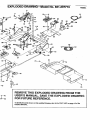
EXPLODED
DRAWING---Model No. 831.29T/73
ROSA
8
7
5
27
52
16
25
• 15
23
51
46
47
:
I
i
49
-45
76
16
REMOVE THIS EXPLODED DRAWING FROM THE
USER'S MANUAL. SAVE THE EXPLODED DRAWING
FOR FUTURE REFERENCE.
To identify the parts shown on this exploded drawing, refer to the PART LiST on page 15 of the
USER'S MANUAL.
_---39
33
41
32
111
45
45
55
I
110
57
67
46
65
36
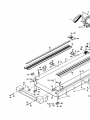
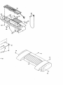
EXPLODED
DRAWING--Model
No, 831.297773
RO299A
86
.o_._e-'-78
8O
79..
75--_
-34
77
##
78
sS
93
75
92*
36,,
78'
I
2O
15
103
34
i_
1!
99
100
i
i
i
9O
|
t
5O
lOl
16
_--83
94
16