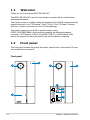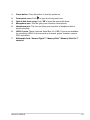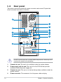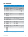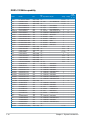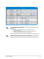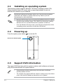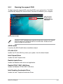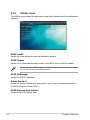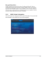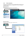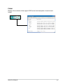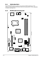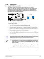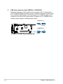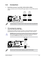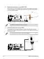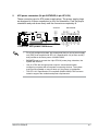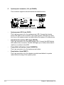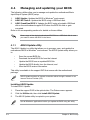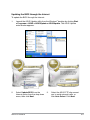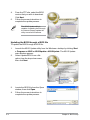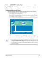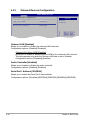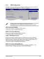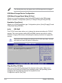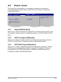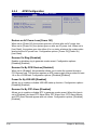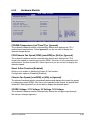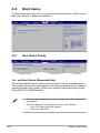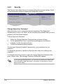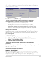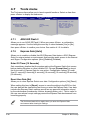
1
P6-P5G41E
ASUS PC (Desktop Barebone)
User’s Manual
E5240
First Edition V1
December 2009
Copyright © 2009 ASUSTeK Computer Inc. All Rights Reserved.
No part of this manual, including the products and software described in it, may be reproduced,
transmitted, transcribed, stored in a retrieval system, or translated into any language in any form or by any
means, except documentation kept by the purchaser for backup purposes, without the express written
permission of ASUSTeK Computer Inc. (“ASUS”).
Product warranty or service will not be extended if: (1) the product is repaired, modified or altered, unless
such repair, modification of alteration is authorized in writing by ASUS; or (2) the serial number of the
product is defaced or missing.
ASUS PROVIDES THIS MANUAL “AS IS” WITHOUT WARRANTY OF ANY KIND, EITHER EXPRESS
OR IMPLIED, INCLUDING BUT NOT LIMITED TO THE IMPLIED WARRANTIES OR CONDITIONS OF
MERCHANTABILITY OR FITNESS FOR A PARTICULAR PURPOSE. IN NO EVENT SHALL ASUS, ITS
DIRECTORS, OFFICERS, EMPLOYEES OR AGENTS BE LIABLE FOR ANY INDIRECT, SPECIAL,
INCIDENTAL, OR CONSEQUENTIAL DAMAGES (INCLUDING DAMAGES FOR LOSS OF PROFITS,
LOSS OF BUSINESS, LOSS OF USE OR DATA, INTERRUPTION OF BUSINESS AND THE LIKE),
EVEN IF ASUS HAS BEEN ADVISED OF THE POSSIBILITY OF SUCH DAMAGES ARISING FROM ANY
DEFECT OR ERROR IN THIS MANUAL OR PRODUCT.
SPECIFICATIONS AND INFORMATION CONTAINED IN THIS MANUAL ARE FURNISHED FOR
INFORMATIONAL USE ONLY, AND ARE SUBJECT TO CHANGE AT ANY TIME WITHOUT NOTICE,
AND SHOULD NOT BE CONSTRUED AS A COMMITMENT BY ASUS. ASUS ASSUMES NO
RESPONSIBILITY OR LIABILITY FOR ANY ERRORS OR INACCURACIES THAT MAY APPEAR IN THIS
MANUAL, INCLUDING THE PRODUCTS AND SOFTWARE DESCRIBED IN IT.
Products and corporate names appearing in this manual may or may not be registered trademarks or
copyrights of their respective companies, and are used only for identification or explanation and to the
owners’ benefit, without intent to infringe.
ii
Table of contents
Notices.......................................................................................................... vi
About this guide........................................................................................ viii
System package contents............................................................................ x
Chapter 1:
System introduction
1.1
Welcome!....................................................................................... 1-2
1.2
Front panel ................................................................................... 1-2
1.3
Rear panel...................................................................................... 1-4
1.4
Internal components..................................................................... 1-7
1.5
Qualified Vendors Lists (QVL)..................................................... 1-8
Chapter 2:
Starting up
2.1
Installing an operating system.................................................... 2-2
2.2
Powering up................................................................................... 2-2
2.3
Support DVD information............................................................. 2-2
2.3.1
Running the support DVD................................................ 2-3
2.3.2
Utilities menu................................................................... 2-4
2.3.3
ASUS Contact information............................................... 2-5
2.3.4
Other information............................................................. 2-6
Chapter 3:
Motherboard info
3.1
Introduction................................................................................... 3-2
3.2
Motherboard layout....................................................................... 3-2
3.3
Jumpers......................................................................................... 3-3
3.4
Connectors.................................................................................... 3-5
Chapter 4:
4.1
BIOS setup
Managing and updating your BIOS............................................. 4-2
4.1.1
ASUS Update utility......................................................... 4-2
4.1.2
ASUS EZ Flash 2 utility.................................................... 4-5
4.1.3
ASUS CrashFree BIOS .................................................. 4-6
iii
Table of contents
4.2
4.3
4.4
4.5
4.6
iv
BIOS setup program..................................................................... 4-7
4.2.1
BIOS menu screen........................................................... 4-8
4.2.2
Menu bar.......................................................................... 4-8
4.2.3
Navigation keys................................................................ 4-8
4.2.4
Menu items...................................................................... 4-9
4.2.5
Sub-menu items............................................................... 4-9
4.2.6
Configuration fields.......................................................... 4-9
4.2.7
Pop-up window................................................................ 4-9
4.2.8
Scroll bar.......................................................................... 4-9
4.2.9
General help.................................................................... 4-9
Main menu................................................................................... 4-10
4.3.1
System Time.................................................................. 4-10
4.3.2
System Date.................................................................. 4-10
4.3.3
SATA1~4.........................................................................4-11
4.3.4
Storage Configuration.................................................... 4-12
4.3.5
System Information........................................................ 4-13
Advanced menu.......................................................................... 4-14
4.4.1
CPU Configuration......................................................... 4-14
4.4.2
Chipset........................................................................... 4-16
4.4.3
Onboard Devices Configuration..................................... 4-18
4.4.4
USB Configuration......................................................... 4-19
4.4.5
PCI PnP......................................................................... 4-20
Power menu................................................................................. 4-21
4.5.1
Suspend Mode............................................................... 4-21
4.5.2
ACPI 2.0 Support .......................................................... 4-21
4.5.3
ACPI APIC Support . ..................................................... 4-21
4.5.4
APM Configuration......................................................... 4-22
4.5.5
Hardware Monitor.......................................................... 4-23
Boot menu................................................................................... 4-24
4.6.1
Boot Device Priority....................................................... 4-24
4.6.2
Boot Settings Configuration........................................... 4-25
Table of contents
4.6.3
4.7
4.8
Security.......................................................................... 4-26
Tools menu.................................................................................. 4-28
4.7.1
ASUS EZ Flash 2........................................................... 4-28
4.7.2
Express Gate [Auto]....................................................... 4-28
Exit menu..................................................................................... 4-29
Notices
Federal Communications Commission Statement
This device complies with Part 15 of the FCC Rules. Operation is subject to the
following two conditions:
• This device may not cause harmful interference, and
• This device must accept any interference received including interference that
may cause undesired operation.
This equipment has been tested and found to comply with the limits for a
Class B digital device, pursuant to Part 15 of the FCC Rules. These limits are
designed to provide reasonable protection against harmful interference in a
residential installation. This equipment generates, uses and can radiate radio
frequency energy and, if not installed and used in accordance with manufacturer’s
instructions, may cause harmful interference to radio communications. However,
there is no guarantee that interference will not occur in a particular installation. If
this equipment does cause harmful interference to radio or television reception,
which can be determined by turning the equipment off and on, the user is
encouraged to try to correct the interference by one or more of the following
measures:
• Reorient or relocate the receiving antenna.
• Increase the separation between the equipment and receiver.
• Connect the equipment to an outlet on a circuit different from that to which the
receiver is connected.
• Consult the dealer or an experienced radio/TV technician for help.
WARNING! The use of shielded cables for connection of the monitor to the
graphics card is required to assure compliance with FCC regulations. Changes
or modifications to this unit not expressly approved by the party responsible for
compliance could void the user’s authority to operate this equipment.
Canadian Department of Communications Statement
This digital apparatus does not exceed the Class B limits for radio noise emissions
from digital apparatus set out in the Radio Interference Regulations of the
Canadian Department of Communications.
This class B digital apparatus complies with Canadian ICES-003.
REACH
Complying with the REACH (Registration, Evaluation, Authorisation, and
Restriction of Chemicals) regulatory framework, we published the chemical
substances in our products at ASUS REACH website at
http://green.asus.com/english/REACH.htm.
vi
Safety information
Electrical safety
•
To prevent electric shock hazard, disconnect the power cable from the electric outlet
before relocating the system.
•
When adding or removing devices to or from the system, ensure that the power cables
for the devices are unplugged before the signal cables are connected. If possible,
disconnect all power cables from the existing system before you add a device.
•
Before connecting or removing signal cables from the motherboard, ensure that all
power cables are unplugged.
•
Seek professional assistance before using an adapter or extension cord. These devices
could interrupt the grounding circuit.
•
Ensure that your power supply is set to the correct voltage in your area. If you are not
sure about the voltage of the electrical outlet you are using, contact your local power
company.
•
If the power supply is broken, do not try to fix it by yourself. Contact a qualified service
technician or your retailer.
Operation safety
•
Before installing the motherboard and adding devices on it, carefully read all the manuals
that came with the package.
•
Before using the product, ensure that all cables are correctly connected and the power
cables are not damaged. If you detect any damage, contact your dealer immediately.
•
To avoid short circuits, keep paper clips, screws, and staples away from connectors,
slots, sockets and circuitry.
•
Avoid dust, humidity, and temperature extremes. Do not place the product in any area
where it may become wet.
•
Place the product on a stable surface.
•
If you encounter technical problems with the product, contact a qualified service
technician or your retailer.
DO NOT throw the motherboard in municipal waste. This product has been
designed to enable proper reuse of parts and recycling. This symbol of the
crossed out wheeled bin indicates that the product (electrical and electronic
equipment) should not be placed in municipal waste. Check local regulations for
disposal of electronic products.
DO NOT throw the mercury-containing button cell battery in municipal waste.
This symbol of the crossed out wheeled bin indicates that the battery should not
be placed in municipal waste.
vii
About this guide
Audience
This guide provides general information and installation instructions about the
ASUS P6-P5G41E barebone system. This guide is intended for experienced users
and integrators with hardware knowledge of personal computers.
How this guide is organized
This guide contains the following parts:
1.
Chapter 1: System introduction
This chapter gives a general description of the ASUS
P6-P5G41E. The chapter lists the system features, including introduction on
the front and rear panel, and internal components.
2.
Chapter 2: Starting up
This chapter helps you power up the system and install drivers and utilities
from the support DVD.
3.
Chapter 3: Motherboard info
This chapter gives information about the motherboard that comes with the
system. This chapter includes the motherboard layout, jumper settings, and
connector locations.
4.
Chapter 4: BIOS setup
This chapter tells how to change system settings through the BIOS Setup
menus and describes the BIOS parameters.
viii
Conventions used in this guide
WARNING: Information to prevent injury to yourself when trying to
complete a task.
CAUTION: Information to prevent damage to the components when
trying to complete a task.
IMPORTANT: Instructions that you MUST follow to complete a task.
NOTE: Tips and additional information to aid in completing a task.
Where to find more information
Refer to the following sources for additional information and for product and
software updates.
1.
ASUS Websites
The ASUS websites worldwide provide updated information on ASUS
hardware and software products. Refer to the ASUS contact information.
2.
Optional Documentation
Your product package may include optional documentation, such as warranty
flyers, that may have been added by your dealer. These documents are not
part of the standard package.
ix
System package contents
Check your P6-P5G41E system package for the following items.
If any of the items is damaged or missing, contact your retailer immediately.
Item description
1.
• ASUS motherboatd
• Power supply unit
• ASUS chassis
2.
ASUS P6-P5G41E barebone system with
Cable
• AC power cable
3.
Support DVD
4.
Quick Installation Guide
This chapter gives a general
description of the ASUS P6-P5G41E.
The chapter lists the system features
including introduction on the front and
rear panel, and internal components.
System introduction
Chapter 1
1.1
Welcome!
Thank you for choosing the ASUS P6-P5G41E!
The ASUS P6-P5G41E is an all-in-one barebone system with a versatile home
entertainment feature.
The system comes in a stylish casing and powered by the ASUS motherboard that
supports the Intel® Core™2 Extreme / Core™2 Duo / Core™2 Quad / Pentium®
dual-core / Celeron® processors in the 775-land package.
The system supports up to 8 GB of system memory using
DDR3-1333/1066 DIMMs. High-resolution graphics via integrated graphics
controller or PCI Express x16 slot, Serial ATA, USB 2.0, and 8-channel audio
feature the system and take you ahead in the world of power computing.
1.2
Front panel
The front panel includes the optical drive bays, power button, and several I/O ports
are located at the front panel.
Front panel 3
1
1
3
4
5
6
2
7
1-2
Chapter 1: System introduction
1.
Power button. Press this button to turn the system on.
2.
Front panel cover. Push
3.
Optical disk drive cover. Push
4.
Microphone port. This Mic (pink) port connects a microphone.
5.
Headphone port. This Line out (lime) port connects a headphone with a
stereo mini-plug.
6.
USB 2.0 ports. These Universal Serial Bus 2.0 (USB 2.0) ports are available
for connecting USB 2.0 devices such as a mouse, printer, scanner, camera,
PDA, and others.
7.
Multimedia Card / Secure Digital™ / MemoryStick® / Memory Stick Pro™
card slot
ASUS P6-P5G41E
to open the front panel cover.
to eject the optical disk drive.
1-3
1.3
Rear panel
The system rear panel includes the power connector and several I/O ports that
allow convenient connection of devices.
2
1
4
6
3
7
8
5
10
9
11
12
14
13
15
Do NOT cover the rear vent , and the ambient temperature is limited up to 35oC
to prevent the system from overheating.
1.
Chassis air vent. The vent is for ventilation inside the system chassis.
2.
Power supply unit fan vent. This vent is for the PSU fan that provides
ventilation inside the power supply unit.
Chassis fan vent. This vent is for the fan that provides ventilation inside the
system chassis.
3.
4.
1-4
Power connector. This connector is for the power cable and plug.
Chapter 1: System introduction
5.
6.
Line In port (light blue). This port connects the tape, CD, DVD player, or
other audio sources.
Line Out port (lime). This port connects a headphone or a speaker. In
4-channel, 6-channel, and 8-channel configuration, the function of this port
becomes Front Speaker Out.
7.
Microphone port (pink). This port connects a microphone.
8.
Side Speaker Out port (gray). This port connects the side speaker in an
8-channel audio configuration.
9. Rear Speaker Out port (black). This port connects the rear speakers in a
4-channel, 6-channel, or 8-channel audio configuration.
10. Center / Subwoofer port (orange). This port connects the center/subwoofer
speakers.
Refer to the audio configuration table below for the function of the audio ports in
2, 4, 6, or 8-channel configuration.
Audio 2, 4, 6, or 8-channel configuration
Port
Light Blue
Lime
Pink
Orange
Black
Gray
Headset.
2-channel
Line In
Line Out
Mic In
–
–
–
4-channel
6-channel
8-channel
Line In
Front Speaker Out
Mic In
–
Rear Speaker Out
–
Line In
Front Speaker Out
Mic In
Center/Subwoofer
Rear Speaker Out
–
Line In
Front Speaker Out
Mic In
Center/Subwoofer
Rear Speaker Out
Side Speaker Out
11. LAN (RJ-45) port. This port allows gigabit connection to a Local Area
Network (LAN) through a network hub. Refer to the table below for the LAN
port LED indications.
LAN port LED indications
Activity/Link Status
Description
OFF
No link
ORANGE
Linked
BLINKING
Data activity
ASUS P6-P5G41E
Status
OFF
ORANGE
GREEN
Speed LED
Description
10 Mbps connection
100 Mbps connection
1 Gbps connection
ACT/LINK SPEED
LED
LED
LAN port
1-5
12. USB 2.0 ports 1 ~ 4. These 4-pin Universal Serial Bus (USB) ports are
available for connecting USB 2.0 devices.
13. Video Graphics Adapter (VGA) port. This 15-pin port is for a VGA monitor or
other VGA-compatible devices.
14. HDMI port. This is a High-Definition Mulltimedia Interface (HDMI) connector,
and is HDCP compliant allowing playback of HD DVD, Blu-Rau discs, and
other protected content.
15. Expansion slot covers. Remove these covers when installing expansion
cards.
1-6
Chapter 1: System introduction
1.4
Internal components
The illustration below is the internal view of the system when you remove the side
cover and the power supply unit. The installed components are labeled for your
reference.
4
2
3
1
5
5
6
1.
2.
3.
4.
Front panel cover
5.
5.25-inch optical drive bays
6.
Hard disk drive bay
7.
Power supply unit (under the HDD bay)
ASUS motherboard
Expansion slot metal brackets
Metal bracket lock
•
Refer to the bundled Quick Installation Guide for installing additional
system components and get assistance from professionals when you
disassemble or assemble the system.
•
Refer to the Chapter 4 in this user guide for motherboard details.
ASUS P6-P5G41E
7
1-7
1.5
Qualified Vendors Lists (QVL)
DDR3-1067MHz capability
1-8
Vendor
Part No.
Size
SS/
DS
Chip Brand
Chip No.
Crucial
CT12864BA1067.8FF
1GB
SS
MICRON
Crucial
CT12864BA1067.8SFD
1GB
SS
Crucial
CT12872BA1067.9FF
1GB
Crucial
CT25664BA1067.16FF
Crucial
DIMM
support
Timing
Voltage
A*
B*
D9KPT
7
-
•
•
MICRON
D9JNL
7
-
•
•
SS
MICRON
D9KPT(ECC)
7
-
•
•
2GB
DS
MICRON
D9KPT
7
-
•
•
CT25664BA1067.16SFD
2GB
DS
MICRON
D9JNL
7
-
•
•
Crucial
CT25672BA1067.18FF
2GB
DS
MICRON
D9KPT(ECC)
7
-
•
•
ELPIDA
EBJ10UE8BAW0-AE-E
1GB
SS
ELPIDA
J1108BABG-DJ-E
7
-
•
•
ELPIDA
EBJ10UE8EDF0-AE-F
1GB
SS
ELPIDA
J1108EDSE-DJ-F
-
-
•
•
ELPIDA
EBJ11RD8BAFA-AE-E
1GB
DS
ELPIDA
J5308BASE-AC-E(ECC)
7
-
ELPIDA
EBJ11UD8BAFA-AG-E
1GB
DS
ELPIDA
J5308BASE-AC-E
8
-
•
•
ELPIDA
EBJ21UE8BAW0-AE-E
2GB
DS
ELPIDA
J1108BABG-DJ-E
7
-
•
•
ELPIDA
EBJ21UE8EDF0-AE-F
2GB
DS
ELPIDA
J1108EDSE-DJ-F
-
-
•
•
Hynix
HMT112U6AFP8C-G7N0
1GB
SS
HYNIX
H5TQ1G83AFPG7C
7
-
•
•
Hynix
HYMT112U64ZNF8-G7
1GB
SS
HYNIX
HY5TQ1G831ZNFP-G7
7
-
•
•
Hynix
HMT125U6AFP8C-G7N0
2GB
DS
HYNIX
H5TQ1G83AFPG7C
7
-
•
•
Hynix
HYMT125U64ZNF8-G7
2GB
DS
HYNIX
HY5TQ1G831ZNFP-G7
7
-
•
•
KINGSTON
KVR1066D3N7/1G
1GB
SS
KINGSTON
D1288JEKAPA7U
7
1.5
•
•
KINGSTON
KVR1066D3N7/2G
2GB
DS
KINGSTON
D1288JEKAPGA7U
7
1.5
•
•
KINGSTON
KVR1066D3N7/2G
2GB
DS
ELPIDA
J1108BABG-DJ-E
-
1.5
•
•
KINGSTON
KVR1066D3N7/4G
4GB
DS
SAMSUNG
K4B2G0846B-HCF8
-
1.5
•
•
MICRON
MT8JTF12864AY-1G1D1
1GB
SS
MICRON
7VD22
7
-
•
•
MICRON
MT8JTF12864AZ-1G1F1
1GB
SS
MICRON
8ZF22 D9KPV
7
-
•
•
MICRON
MT8JTF12864AZ-1G1F1
1GB
SS
MICRON
D9KPT
7
-
•
•
MICRON
MT9JSF12872AZ-1G1F1
1GB
SS
MICRON
D9KPT(ECC)
7
-
•
•
MICRON
MT16JTF25664AY-1G1D1
2GB
DS
MICRON
7VD22
7
-
•
•
MICRON
MT16JTF25664AZ-1G1F1
2GB
DS
MICRON
8ZF22 D9KPV
7
-
•
•
MICRON
MT16JTF25664AZ-1G1F1
2GB
DS
MICRON
D9KPT
7
-
•
•
MICRON
MT18JSF25672AZ-1G1F1
2GB
DS
MICRON
D9KPT(ECC)
7
-
•
•
SAMSUNG
M378B5273BH1-CF8
4GB
DS
SAMSUNG
K4B2G0846B-HCF8
8
1.5
•
Transcend
TS256MLK64V1U
2GB
DS
ELPIDA
J1108BABG-AE-E
7
-
•
•
Asint
SLY3128M8-EAE
1GB
SS
Asint
DDRIII1208-AE
-
-
•
•
Asint
SLZ3128M8-EAE
2GB
DS
Asint
DDRIII1208-AE
-
-
•
•
Elixir
M2Y2G64CB8HA9N-BE
2GB
DS
-
-
-
-
•
•
WINTEC
3DU3191A-10
1GB
DS
Qimonda
IDSH51-03A1F1C-10F
7
-
•
•
Chapter 1: System introduction
DDR3-1333MHz capability
SS/ Chip Brand Chip No.
DS
Timing
DIMM
Voltage support
A* B*
Vendor
Part No.
Size
A-DATA
AD3133301GOU
1GB
SS
A-DATA
AD30908C8D-15IG
-
-
•
•
A-DATA
AD31333002GOU
2GB
DS
A-DATA
AD30908C8D-15IG
-
-
•
•
A-DATA
AD3U1333B2G9-2
2GB
DS
A-DATA
AD30908C8D-15IG
-
-
•
•
A-DATA
AX3U1333PB2G7-2P
4GB(2 x 2GB)
DS
-
-
7-7-7-20
1.651.85
•
•
A-DATA
AD3U1333C4G9-B
4GB
DS
Hynix
H5TQ2G83AFRH9C
1333-9-99-24
-
•
•
A-DATA
AD31333E002G0U
6GB(3 x 2GB)
DS
-
-
7-7-7-20
1.651.85
•
•
A-DATA
AX3U1333PB2G7-3P
6GB(3 x 2GB)
DS
-
-
7-7-7-20
1.651.85
•
•
CORSAIR
TR3X3G1333C9 (Ver2.1)
3GB(3 x 1GB)
SS
-
-
9-9-9-24
1.5
•
•
CORSAIR
CM3X1024-1333C9DHX
1GB
DS
-
-
-
1.1
•
•
CORSAIR
“BoxP/N:TWIN3X20482GB(2 x 1GB)
1333C9
(CM3X1024-1333C9)Ver1.1”
DS
-
-
9-9-9-24
1.70
•
•
CORSAIR
CM3X2G1333C9
2GB
DS
-
-
9-9-9-24
1.5
•
•
CORSAIR
“BoxP/N:
TW3X4G1333C9DHX
(CM3X20481333C9DHX)Ver3.2”
4GB(2 x 2GB)
DS
-
-
9-9-9-24
1.70
•
•
CORSAIR
TR3X6G1333C9 (Ver2.1)
6GB(3 x 2GB)
DS
-
-
9-9-9-24
1.5
•
•
CORSAIR
CMX8GX3M4A1333C9
8GB(4 x 2GB)
DS
-
-
9-9-9-24
1.5
•
•
Crucial
CT12864BA1339.8FF
1GB
SS
MICRON
D9KPT
9
-
•
•
Crucial
CT12864BA1339.8SFD
1GB
SS
MICRON
MT8JF12864AY-1G4D1
-
-
•
•
Crucial
CT12872BA1339.9FF
1GB
SS
MICRON
D9KPT(ECC)
9
-
•
•
Crucial
BL25664BN1337.16FF(XMP) 2GB
DS
-
-
7-7-7-24
1.65
•
•
Crucial
CT25664BA1339.16FF
2GB
DS
MICRON
D9KPT
9
-
•
•
Crucial
CT25664BA1339.16SFD
2GB
DS
MICRON
D9JNM
-
-
•
•
Crucial
CT25672BA1339.18FF
2GB
DS
MICRON
D9KPT(ECC)
9
-
•
•
Crucial
BL25664BA1336.16SFB1
4GB(2 x 2GB)
DS
NA
-
6-6-6-20
1.8
•
•
ELPIDA
EBJ10UE8BAW0-DJ-E
1GB
SS
ELPIDA
J1108BABG-DJ-E
9
-
•
•
ELPIDA
EBJ10UE8BDF0-DJ-F
1GB
SS
ELPIDA
J1108BDSE-DJ-F
-
-
•
•
ELPIDA
EBJ10UE8EDF0-DJ-F
1GB
SS
ELPIDA
J1108EDSE-DJ-F
-
-
•
•
ELPIDA
EBJ21UE8BAW0-DJ-E
2GB
DS
ELPIDA
J1108BABG-DJ-E
9
-
•
•
ELPIDA
EBJ21UE8BDF0-DJ-F
2GB
DS
ELPIDA
J1108BDSE-DJ-F
-
-
•
•
ELPIDA
EBJ21UE8EDF0-DJ-F
2GB
DS
ELPIDA
J1108EDSE-DJ-F
-
-
•
•
G.SKILL
F3-10600CL7D-2GBPI
2GB(2 x 1GB)
SS
-
-
-
1.65
•
•
G.SKILL
F3-10600CL8D-2GBHK
2GB(2 x 1GB)
SS
-
-
-
1.65
•
•
G.SKILL
F3-10666CL7T6GBPK(XMP)
2GB
DS
-
-
7-7-7-18
1.5-1.6
•
•
G.SKILL
F3-10666CL7D4GBPI(XMP)
4GB(2 x 2GB)
DS
-
-
7-7-7-21
1.5
•
•
G.SKILL
F3-10666CL7D4GBRH(XMP)
4GB(2 x 2GB)
DS
-
-
7-7-7-21
1.5
•
•
G.SKILL
F3-10666CL8D4GBHK(XMP)
4GB(2 x 2GB)
DS
-
-
8-8-8-21
1.5-1.6
•
•
G.SKILL
F3-10666CL8D4GBRM(XMP)
4GB(2 x 2GB)
DS
-
-
8-8-8-21
1.5-1.6
•
•
continued on the next page
ASUS P6-P5G41E
1-9
DDR3-1333MHz capability
1-10
DIMM
Voltage support
A* B*
Vendor
Part No.
Size
SS/
DS Chip Brand Chip No.
Timing
G.SKILL
F3-10666CL9T-6GBNQ
6GB(3 x 2GB)
DS
-
-
9-9-9-24
1.5
•
•
GEIL
GG34GB1333C9DC
4GB(2 x 2GB)
DS
GEIL
GL1L128M88BA12N
9-9-9-24
1.3
•
•
GEIL
GV34GB1333C7DC
4GB(2 x 2GB)
DS
-
-
7-7-7-24
1.5
•
•
Hynix
HMT112U6BFR8C-H9
1GB
SS
Hynix
H5TQ1G83BFR
9
-
•
Hynix
HMT125U6BFR8C-H9
2GB
DS
Hynix
H5TQ1G83BFR
9
-
•
•
Hynix
HMT125U6BFR8C-H9
2GB
DS
Hynix
H5TQ1G83BFRH9C
9
-
•
•
KINGSTON
KVR1333D3N9/2G
2GB
DS
Qimonda
IDSH1G-03A1F1C-13H
9
1.5
•
•
KINGSTON
KVR1333D3N9/4G
4GB
DS
SAMSUNG
K4B2G0846B-HCH9
9
1.5
•
•
MICRON
MT8JTF12864AZ-1G4F1
1GB
SS
MICRON
9FF22 D9KPT
9
-
•
•
MICRON
MT8JTF12864AZ-1G4F1
1GB
SS
MICRON
D9KPT
9
-
•
•
MICRON
MT9JSF12872AZ-1G4F1
1GB
SS
MICRON
D9KPT(ECC)
9
-
•
•
MICRON
MT16JF25664AZ-1G4F1
2GB
DS
MICRON
D9KPT
9
-
•
•
MICRON
MT16JTF25664AZ-1G4F1
2GB
DS
MICRON
9FF22 D9KPT
9
-
•
•
MICRON
MT18JSF25672AZ-1G4F1
2GB
DS
MICRON
D9KPT(ECC)
9
-
•
•
OCZ
OCZ3RPX1333EB2GK
2GB(2 x 1GB)
SS
NANYA
-
6-5-5
1.85
•
•
OCZ
OCZ3G1333LV3GK
3GB(3 x 1GB)
SS
-
-
9-9-9
1.65
•
•
OCZ
OCZ3P1333LV3GK
3GB(3 x 1GB)
SS
-
-
7-7-7
1.65
•
•
OCZ
OCZ3P13332GK
1GB
DS
-
-
7-7-7-20
-
•
•
OCZ
OCZ3G13334GK
4GB(2 x 2GB)
DS
-
-
9
1.7
•
•
OCZ
OCZ3G1333ULV4GK
4GB(2 x 2GB)
DS
-
-
8-8-8
1.65
•
OCZ
OCZ3G1333LV6GK
6GB(3 x 2GB)
DS
-
-
9-9-9
1.65
•
•
OCZ
OCZ3P1333LV6GK
6GB(3 x 2GB)
DS
-
-
7-7-7
1.65
•
•
OCZ
OCZX1333LV6GK(XMP)
6GB(3 x 2GB)
DS
NA
-
8-8-8
1.6
•
•
PSC
AL7F8G73D-DG1
1GB
SS
PSC
A3P1GF3DGF
-
-
•
•
PSC
AL8F8G73D-DG1
2GB
DS
PSC
A3P1GF3DGF
-
-
•
•
SAMSUNG
M378B2873DZ1-CH9
1GB
SS
SAMSUNG
K4B1G0846D
9
-
•
•
SAMSUNG
M378B2873EH1-CH9
1GB
SS
SAMSUNG
K4B1G0846E
-
-
•
•
SAMSUNG
M391B2873DZ1-CH9
1GB
SS
SAMSUNG
K4B1G0846D(ECC)
9
-
•
•
SAMSUNG
M378B5673DZ1-CH9
2GB
DS
SAMSUNG
K4B1G0846D
9
-
•
•
SAMSUNG
M378B5673EH1-CH9
2GB
DS
SAMSUNG
K4B1G0846E
-
-
•
•
SAMSUNG
M391B5673DZ1-CH9
2GB
DS
SAMSUNG
K4B1G0846D(ECC)
9
-
•
•
SAMSUNG
M378B5273BH1-CH9
4GB
DS
SAMSUNG
K4B2G0846B-HCH9
9
-
•
•
Super Talent
W1333UX2GB(XMP)
2GB(2 x 1GB)
SS
-
-
8
1.8
•
•
Transcend
TS128MLK64V3U
1GB
SS
SAMSUNG
K4B1G0846D
9
-
•
•
Transcend
TS256MLK64V3U
2GB
DS
SAMSUNG
K4B1G0846D
9
-
•
•
Asint
SLY3128M8-EDJ
1GB
SS
Asint
DDRIII1208-DJ
-
-
•
•
Asint
SLY3128M8-EDJE
1GB
SS
ELPIDA
J1108BASE-DJ-E
-
-
•
•
Asint
SLZ3128M8-EDJ
2GB
DS
Asint
DDRIII1208-DJ
-
-
•
•
Asint
SLZ3128M8-EDJE
2GB
DS
ELPIDA
J1108BASE-DJ-E
-
-
•
•
ASUS
N/A
1GB
DS
-
-
-
-
•
•
ATP
AQ28M64A8BJH9S
1GB
SS
SAMSUNG
K4B1G0846E
-
-
•
•
ATP
AQ28M72D8BJH9S
1GB
SS
SAMSUNG
K4B1G0846D(ECC)
-
-
•
•
ATP
AQ56M64B8BJH9S
2GB
DS
SAMSUNG
K4B1G0846D
-
-
•
•
ATP
AQ56M72E8BJH9S
2GB
DS
SAMSUNG
K4B1G0846D(ECC)
-
-
•
•
BUFFALO
FSX1333D3G-1G
1GB
SS
-
-
-
-
•
•
BUFFALO
FSH1333D3G-T3G(XMP)
3GB(3 x 1GB)
SS
-
-
7-7-7-20
-
•
•
Chapter 1: System introduction
DIMM
Voltage support
A* B*
Vendor
Part No.
Size
SS/ Chip Brand Chip No.
DS
BUFFALO
FSX1333D3G-2G
2GB
DS
-
-
-
-
•
•
EK Memory
EKM324L28BP8-I13
4GB(2 x 2GB)
DS
-
-
9
-
•
•
Elixir
M2Y2G64CB8HA9N-CG
2GB
DS
-
-
-
-
•
•
Patriot
PDC32G1333LLK
1GB
SS
PATRIOT
-
7
1.7
•
•
Patriot
PVT33G1333ELK
3GB(3 x 1GB)
SS
-
-
9-9-9-24
1.65
•
•
Patriot
PVS34G1333ELK
4GB(2 x 2GB)
DS
-
-
9-9-9-24
1.5
•
•
Patriot
PVS34G1333LLK
4GB(2 x 2GB)
DS
-
-
7-7-7-20
1.7
•
•
Patriot
PVT36G1333ELK
6GB(3 x 2GB)
DS
-
-
9-9-9-24
1.65
•
•
Silicon Power
SP001GBLTU1333S01
1GB
SS
NANYA
NT5CB128M8AN-CG
-
-
•
•
Silicon Power
SP001GBLTU133S02
1GB
SS
S-POWER
I0YT3E0
9
-
•
•
Silicon Power
SP002GBLTU133S02
2GB
DS
S-POWER
I0YT3E0
9
-
•
•
Apacer
75.073C1.G02
1GB
SS
Apacer
AM5D5808DEWSJG
-
•
•
NANYA
NT1GC64B88A0NF-CG
1GB
SS
NANYA
NT5CB128MBAN-CG
-
-
•
•
NANYA
NT2GC64B8HA0NF-CG
2GB
DS
NANYA
NT5CB128MBAN-CG
-
-
•
•
Asint
SLY3128M8-EDJED
1GB
SS
ELPIDA
J1108BDBG-DJ-F
-
-
•
•
Asint
SLZ3128M8-EDJED
2GB
DS
ELPIDA
J1108BDBG-DJ-F
-
•
•
Timing
SS - Single-sided / DS - Double-sided
DIMM support:
• A*: Supports one module inserted in any slot as Single-channel
memory configuration.
• B*: Supports one pair of modules inserted into both the yellow slots
as one pair of Dual-channel memory configuration.
Visit the ASUS website at www.asus.com for the latest QVLs.
ASUS P6-P5G41E
1-11
Chapter 2
Starting up
This chapter helps you power up the
system and install drivers and utilities
from the support DVD.
2.1
Installing an operating system
The barebone system supports Windows® XP/Vista/7 operating systems (OS).
Always install the latest OS version and corresponding updates so you can
maximize the features of your hardware.
Motherboard settings and hardware options vary. Use the setup procedures
presented in this chapter for general reference only. Refer to your OS
documentation for more information.
2.2
•
Windows XP OS setup cannot recognize Serial ATA hard drives in a RAID
set without the necessary drivers. Use a RAID driver disk when installing
Windows XP OS to a Serial ATA hard drive included in a RAID set.
•
From the Windows XP setup screen, press F6 when prompted then follow
succeeding screen instructions to install the SATA drivers.
Powering up
Press the system power button ( ) to enter the OS.
Press to turn ON the system
2.3
Support DVD information
The support DVD that came with the system contains useful software and several
utility drivers that enhance the system features.
2-2
•
Screen display and driver options may not be the same for different
operating system versions.
•
The contents of the support DVD are subject to change at any time without
notice. Visit the ASUS website at www.asus.com for updates.
Chapter 2: Starting up
2.3.1
Running the support DVD
To begin using the support DVD, place the DVD in your optical drive. The DVD
automatically displays the Drivers menu if Autorun is enabled in your computer.
Click an icon to
display support
DVD/motherboard
information
Click an item to install
If Autorun is NOT enabled in your computer, browse the contents of the support
DVD to locate the file ASSETUP.EXE from the BIN folder. Double-click the
ASSETUP.EXE to run the DVD.
ASUS InstAll
Launches the ASUS InstAll driver installation wizard.
PC-cillin 2010
Installs the PC-cillin 2010 to protect your system from the latest threats.
Intel Chipset Driver
Installs the Intel® chipset driver.
Realtek Audio Driver
Installs the Realtek audio driver and application.
Realtek RTL8111B/C LAN Driver
Installs the Realtek® RTL8111B/C LAN driver.
Intel Graphics Accelerator Driver
Installs the Intel® Graphics Accelerator Driver.
ASUS P6-P5G41E
2-3
2.3.2
Utilities menu
The Utilities menu shows the applications and other software that the motherboard
supports.
ASUS InstAll
Installs all of the utilities through the Installation Wizard.
ASUS Update
Allows you to download the latest version of the BIOS from the ASUS website.
Before using the ASUS Update, make sure that you have an Internet connection
so you can connect to the ASUS website.
ASUS AI Manager
Installs the ASUS AI Manager.
Adobe Reader 9
Installs the Adobe® Reader that allows you to open, view, and print documents in
Portable Document Format (PDF).
ASUS Express Gate Installer
Installs the ASUS Express Gate.
2-4
Chapter 2: Starting up
Microsoft DirectX 9.0c
Installs the Microsoft® DirectX 9.0c driver. The Microsoft DirectX® 9.0c is a
multimedia technology that enhances computer graphics and sound. DirectX®
improves the multimedia features of you computer so you can enjoy watching
TV and movies, capturing videos, or playing games in your computer. Visit the
Microsoft website (www.microsoft.com) for updates.
2.3.3
ASUS Contact information
Click the Contact tab to display the ASUS contact information. You can also find
this information on the inside front cover of this user guide.
ASUS P6-P5G41E
2-5
2.3.4
Other information
The icons on the top right corner of the screen give additional information on the
motherboard and the contents of the support DVD. Click an icon to display the
specified information.
Motherboard Info
Displays the general specifications of the motherboard.
Browse this DVD
Displays the support DVD contents in graphical format.
2-6
Chapter 2: Starting up
Filelist
Displays the contents of the support DVD and a brief description of each in text
format.
ASUS P6-P5G41E
2-7
2-8
Chapter 2: Starting up
This chapter gives information about
he motherboard that comes with the
system. This chapter includes the
motherboard layout, jumper settings,
and connector locations.
Motherboard info
Chapter 3
USBPW5-6
ATX12V
DDR3 DIMM_B1 (64bit, 240-pin module)
33.5cm(13.2in)
Intel®
EAGLELAKE
G41
DDR3 DIMM_A1 (64bit, 240-pin module)
LGA775
RTM
870T-954
CLRTC
SATA4
SATA3
Lithium Cell
CMOS Power
PCIEX16
8Mb
BIOS
SATA2
SATA1
CHA_FAN1
Intel®
ICH7
EATXPWR
BUZZER
P5QPL10T
F_PANEL
FRONT_
AUD
USB56
CR_CON1
CPU_FAN
ALC
1200
AUDIO
LAN1_USB34
USB12
DEBUGPORT
SPDIF_OUT
RTL
8111C
COM1
USBPW1-4
PCIEX1_1
Motherboard layout
3.2
Chapter 3: Motherboard info
3-2
Introduction
3.1
The P6-P5G41E barebone system comes with an ASUS motherboard. This
chapter provides technical information about the motherboard for future upgrades
or system reconfiguration.
17.5cm(6.9in)
Super
I/O
VGA_HDMI
3.3
1.
Jumpers
Clear RTC RAM (3-pin CLRTC)
This jumper allows you to clear the Real Time Clock (RTC) RAM in
CMOS. You can clear the CMOS memory of date, time, and system setup
parameters by erasing the CMOS RTC RAM data. The onboard button
cell battery powers the RAM data in CMOS, which include system setup
information such as system passwords.
CLRTC
2
1
2
3
P5QPL10T
Normal
(Default)
Clear RTC
P5QPL10T Clear RTC RAM
To erase the RTC RAM:
1. Turn OFF the computer and unplug the power cord.
2. Move the jumper cap from pins 1-2 (default) to pins 2-3. Keep the cap
on pins 2-3 for about 5-10 seconds, then move the cap back to pins 1-2.
3. Plug the power cord and turn ON the computer.
4. Hold down the <Del> key during the boot process and enter BIOS setup
to re-enter data.
Except when clearing the RTC RAM, never remove the cap on CLRTC jumper
default position. Removing the cap will cause system boot failure!
•
If the steps above do not help, remove the onboard battery and move the
jumper again to clear the CMOS RTC RAM data. After clearing the CMOS,
reinstall the battery.
•
You do not need to clear the RTC when the system hangs due to
overclocking. For system failure due to overclocking, use the CPU
Parameter Recall (C.P.R.) feature. Shut down and reboot the system, then
the BIOS automatically resets parameter settings to default values.
ASUS P6-P5G41E
3-3
2.
USB device wake-up (3-pin USBPW1-4, USBPW5-6)
Set these jumpers to +5V to wake up the computer from S1 sleep mode
(CPU stopped, DRAM refreshed, system running in low power mode) using
the connected USB devices. Set these jumpers to +5VSB to wake up the
compurer from S3 and S4 sleep modes (no power to CPU, DRAM in slow
refresh, power supply in reduced power mode).
USBPW1-4
1
2
+5V
P5QPL10T
2 3
+5VSB
(Default)
USBPW5-6
1
P5QPL10T USB Device Wake Up
3-4
2
+5V
(Default)
2 3
+5VSB
Chapter 3: Motherboard info
3.4
1.
Connectors
Serial ATA connectors (7-pin SATA1, SATA2, SATA3, SATA4)
These connectors are for the Serial ATA signal cables for Serial ATA hard disk
drives.
SATA3
GND
RSATA_RXP3
RSATA_RXN3
GND
RSATA_TXP3
RSATA_TXN3
GND
GND
RSATA_RXP1
RSATA_RXN1
GND
RSATA_TXP1
RSATA_TXN1
GND
SATA1
SATA4
GND
RSATA_RXP4
RSATA_RXN4
GND
RSATA_TXP4
RSATA_TXN4
GND
GND
RSATA_RXP2
RSATA_RXN2
GND
RSATA_TXP2
RSATA_TXN2
GND
SATA2
P5QPL10T
P5QPL10T SATA connectors (ICH7®)
Install the Windows® XP Service Pack 2 or later version before using Serial ATA.
2.
CPU and chassis fan connectors.
(4-pin CPU_FAN, 4-pin CHA_FAN1)
Connect the fan cables to the fan connectors on the motherboard, ensuring
that the black wire of each cable matches the ground pin of the connector.
DO NOT forget to connect the fan cables to the fan connectors. Insufficient air
flow inside the system may damage the motherboard components. These are
not jumpers! DO NOT place jumper caps on the fan connectors!
P5QPL10T
CPU FAN PWM
CPU FAN IN
CPU FAN PWR
GND
CPU_FAN
CHA_FAN1
P5QPL10T fan connectors
GND
CPU FAN PWR
CPU FAN IN
CPU FAN PWM
Only the 4-pin CPU fan connector supports the ASUS Q-Fan feature.
ASUS P6-P5G41E
3-5
3.
Digital Audio connector (4-1 pin SPDIF_OUT)
This connector is for the S/PDIF audio module to allow digital sound output.
Connect one end of the S/PDIF audio cable to this connector and the other
end to the S/PDIF module.
+5V
SPDIFOUT
GND
SPDIF_OUT
P5QPL10T
P5QPL10T Digital audio connector
The S/PDIF out module is purchased separately.
4.
Serial port connectors (10-1 pin COM1)
The connector is for a serial (COM) port. Connect the serial port module
cable to the connector, then install the module to a slot opening at the back of
the system chassis.
The serial port bracket (COM1) is purchased separately.
COM1
PIN 1
P5QPL10T
P5QPL10T Serial port (COM1) connector
3-6
Chapter 3: Motherboard info
5.
ATX power connectors (24-pin EATXPWR, 4-pin ATX12V)
These connectors are for ATX power supply plugs. The power supply plugs
are designed to fit these connectors in only one orientation. Find the proper
orientation and push down firmly until the connectors completely fit.
EATXPWR
P5QPL10T ATX power connectors
+3 Volts
+12 Volts
+12 Volts
+5V Standby
Power OK
GND
+5 Volts
GND
+5 Volts
GND
+3 Volts
+3 Volts
GND
GND
PIN 1
PIN 1
GND
+5 Volts
+5 Volts
+5 Volts
-5 Volts
GND
GND
GND
PSON#
GND
-12 Volts
+3 Volts
P5QPL10T
+12V DC
+12V DC
ATX12V
•
For a fully configured system, we recommend that you use a power supply
unit (PSU) that complies with ATX 12 V Specification 2.0 (or later version)
and provides a minimum power of 200W~250W.
•
DO NOT forget to connect the 4-pin ATX12V power plug; otherwise, the
system will not boot.
•
Use of a PSU with a higher power output is recommended when
configuring a system with more power-consuming devices. The system
may become unstable or may not boot up if the power is inadequate.
• The ATX 12 V Specification 2.0-compliant (200W~250W) PSU has been
tested to support the motherboard power requirements.
ASUS P6-P5G41E
3-7
6.
System panel connector (10-1 pin PANEL)
This connector supports several chassis-mounted functions.
PLED+
PLEDPWR
GND
PWR LED PWR BTN
P5QPL10T
F_PANEL
IDE_LED+
IDE_LEDGround
Reset
PIN 1
HD_LED
RESET
P5QPL10T System panel connector
•
System power LED (2-pin PLED)
This 2-pin connector is for the system power LED. Connect the chassis
power LED cable to this connector. The system power LED lights up when
you turn on the system power, and blinks when the system is in sleep mode.
•
Hard disk drive activity LED (2-pin HDLED)
This 2-pin connector is for the HDD Activity LED. Connect the HDD Activity
LED cable to this connector. The IDE LED lights up or flashes when data is
read from or written to the HDD.
•
Power/Soft-off button (2-pin PWRBTN)
This 2-pin connector is for the system power button.
•
Reset button (2-pin RESET)
This 2-pin connector is for the chassis-mounted reset button for system
reboot without turning off the system power.
3-8
Chapter 3: Motherboard info
Chapter 4
BIOS setup
This chapter tells how to change
system settings through the BIOS
Setup menus and describes the BIOS
parameters.
4.1
Managing and updating your BIOS
The following utilities allow you to manage and update the motherboard Basic
Input/Output System (BIOS) setup.
1.
ASUS Update: Updates the BIOS in Windows® environment.
2.
ASUS EZ Flash 2: Updates the BIOS using a USB flash disk.
3.
ASUS CrashFree BIOS 3: Updates the BIOS using a bootable USB flash
disk or the motherboard support DVD when the BIOS file fails or gets
corrupted.
Refer to the corresponding sections for details on these utilities.
Save a copy of the original motherboard BIOS file to a USB flash disk in case
you need to restore the BIOS in the future.
4.1.1
ASUS Update utility
The ASUS Update is a utility that allows you to manage, save, and update the
motherboard BIOS in Windows® environment. The ASUS Update utility allows you
to:
•
Save the current BIOS file
•
Download the latest BIOS file from the Internet
•
Update the BIOS from an updated BIOS file
•
Update the BIOS directly from the Internet, and
•
View the BIOS version information.
This utility is available in the support DVD that comes with the motherboard
package.
ASUS Update requires an Internet connection either through a network or an
Internet Service Provider (ISP).
Installing ASUS Update
To install ASUS Update:
1.
Place the support DVD in the optical drive. The Drivers menu appears.
2.
Click the Utilities tab, then click Install ASUS Update.
3.
The ASUS Update utility is copied to your system.
Quit all Windows® applications before you update the BIOS using this utility.
4-2
Chapter 4: BIOS setup
Updating the BIOS through the Internet
To update the BIOS through the Internet:
1.
Launch the ASUS Update utility from the Windows® desktop by clicking Start
> Programs > ASUS > ASUSUpdate > ASUSUpdate. The ASUS Update
main window appears.
2.
Select Update BIOS from the
Internet option from the drop‑down
menu, then click Next.
ASUS P6-P5G41E
3.
Select the ASUS FTP site nearest
you to avoid network traffic, or
click Auto Select. Click Next.
4-3
4.
From the FTP site, select the BIOS
version that you wish to download.
Click Next.
5.
Follow the screen instructions to
complete the update process.
The ASUS Update utility is
capable of updating itself through
the Internet. Always update the
utility to avail all its features.
Updating the BIOS through a BIOS file
To update the BIOS through a BIOS file:
1.
Launch the ASUS Update utility from the Windows® desktop by clicking Start
> Programs > ASUS > ASUSUpdate > ASUSUpdate. The ASUS Update
main window appears.
2.
Select Update BIOS from a file
option from the drop‑down menu,
then click Next.
3.
Locate the BIOS file from the Open
window, then click Open.
4.
Follow the screen instructions to
complete the update process.
P6P5G41E.rom
P6P5G41E
4-4
Chapter 4: BIOS setup
4.1.2
ASUS EZ Flash 2 utility
The ASUS EZ Flash 2 feature allows you to update the BIOS without using an
OS‑based utility.
To update the BIOS using EZ Flash 2:
1.
Insert the USB flash disk that contains the latest BIOS file to the USB port,
then launch EZ Flash 2 in any of these two ways:
•
•Enter the BIOS setup program. Go to the Tools menu to select EZ Flash
2 and press <Enter> to enable it.
Press <Tab> to switch between drives until the correct BIOS file is found.
Press <Alt> + <F2> during POST.
ASUSTek EZ Flash 2 BIOS ROM Utility V3.44
FLASH TYPE: MXIC 25L8005
Current ROM
BOARD: P6-P5g41e
VER: 0202 (H:01 B:07)
DATE: 12/15/2009
Update ROM
BOARD: Unknown
VER: Unknown
DATE: Unknown
PATH: A:\
A:
Note
[Enter] Select or Load
[Tab] Switch
[V] Drive Info
[Up/Down/Home/End] Move
[B] Backup
[Esc] Exit
2. When the correct BIOS file is found, EZ Flash 2 performs the BIOS
update process and automatically reboots the system when done.
•
Only a USB flash disk with FAT 32/16 format and single partition can
support the ASUS EZ Flash 2 utility.
•
Do not shut down or reset the system while updating the BIOS to prevent
system boot failure!
ASUS P6-P5G41E
4-5
4.1.3
ASUS CrashFree BIOS
The ASUS CrashFree BIOS is an auto recovery tool that allows you to restore
the BIOS file when it fails or gets corrupted during the updating process. You can
restore a corrupted BIOS file using the motherboard support DVD or a removable
device that contains the updated BIOS file.
•
Before using this utility, rename the BIOS file in the removable device into
P6p5g41e.ROM.
•
The BIOS file in the support DVD may not be the latest version. Download
the latest BIOS file from the ASUS website at www.asus.com.
•
The removable device that ASUS CrashFree BIOS support vary with
motherboard models. For motherboards without the floppy connector,
prepare a USB flash disk before using this utility.
Recovering the BIOS
To recover the BIOS:
1.
Turn on the system.
2.
Insert the support DVD to the optical drive or the removable device that
contains the BIOS file to the USB port or to the floppy disk drive, if supported.
3.
The utility automatically checks the devices for the BIOS file. When found,
the utility reads the BIOS file and starts flashing the corrupted BIOS file.
4.
Turn off the system after the utility completes the updating process and turn
on again.
DO NOT shut down or reset the system while updating the BIOS! Doing so can
cause system boot failure!
Ensure to load the BIOS default settings to ensure system compatibility and
stability. Select the Load Setup Defaults item under the Exit menu. Refer to
section 4.8 Exit Menu for details.
4-6
Chapter 4: BIOS setup
4.2
BIOS setup program
Use the BIOS Setup program to update the BIOS or configure its parameters. The
BIOS screens include navigation keys and brief online help to guide you in using
the BIOS Setup program.
Entering BIOS Setup at startup
To enter BIOS Setup at startup:
•
Press <Delete> during the Power-On Self Test (POST). If you do not press
<Delete>, POST continues with its routines.
Entering BIOS Setup after POST
To enter BIOS Setup after POST:
•
Press <Ctrl>+<Alt>+<Del> simultaneously.
•
Press the reset button on the system chassis.
•
Press the power button to turn the system off then back on. Do this option only
if you failed to enter BIOS Setup using the first two options.
Using the power button, reset button, or the <Ctrl>+<Alt>+<Del> keys to
force reset from a running operating system can cause damage to your data
or system. We recommend to always shut down the system properly from the
operating system.
•
The default BIOS settings for this motherboard apply for most conditions
to ensure optimum performance. If the system becomes unstable after
changing any BIOS settings, load the default settings to ensure system
compatibility and stability. Select the Load Default Settings item under the
Exit Menu. See section 4.8 Exit Menu.
•
The BIOS setup screens shown in this section are for reference purposes
only, and may not exactly match what you see on your screen.
•
Visit the ASUS website (www.asus.com) to download the latest BIOS file for
this motherboard.
ASUS P6-P5G41E
4-7
4.2.1
BIOS menu screen
Menu items
Main
Menu bar
Advanced
Power
Configuration fields
BIOS SETUP UTILITY
Boot
Tools
System Time
System Date
SATA
SATA
SATA
SATA
1
2 3 4 [12:56:38]
[Mon 11/23/2009
:[Not
:[Not
:[Not
:[Not
Detected]
Detected]
Detected]
Detected]
General help
Exit
Use [ENTER], [TAB]
or [SHIFT-TAB] to
select a field.
Use [+] or [-] to
configure system time.
Storage Configuration System Information
Enter
F1
F10
ESC
Select Screen
Select Item
Go to Sub-screen
General Help
Save and Exit
Exit
v02.61 (C)Copyright 1985-2009, American Megatrends, Inc.
Sub-menu items
4.2.2
Navigation keys
Menu bar
The menu bar on top of the screen has the following main items:
Main
For changing the basic system configuration
Advanced
For changing the advanced system settings
Power
For changing the advanced power management (APM)
configuration
Boot
For changing the system boot configuration
Tools
For configuring options for special functions
Exit
For selecting the exit options and loading default settings
To select an item on the menu bar, press the right or left arrow key on the keyboard
until the desired item is highlighted.
4.2.3
Navigation keys
At the bottom right corner of a menu screen are the navigation keys for that
particular menu. Use the navigation keys to select items in the menu and change
the settings.
Some of the navigation keys differ from one screen to another.
4-8
Chapter 4: BIOS setup
4.2.4
Menu items
The highlighted item on the menu bar displays
the specific items for that menu. For example,
selecting Main shows the Main menu items.
The other items (Advanced, Power, Boot,
Tool, and Exit) on the menu bar have their
respective menu items.
4.2.5
Select Screen
Select Item
Enter Go to Sub-screen
F1
General Help
F10
Save and Exit
ESC
Exit
Main menu items
Sub-menu items
A solid triangle before each item on any menu screen means that the iteam has a
sub-menu. To display the sub-menu, select the item and press <Enter>.
4.2.6
Configuration fields
These fields show the values for the menu items. If an item is user- configurable,
you can change the value of the field opposite the item. You cannot select an item
that is not user-configurable.
A configurable field is enclosed in brackets, and is highlighted when selected. To
change the value of a field, select it then press <Enter> to display a list of options.
Refer to “2.2.7 Pop-up window.”
4.2.7
Pop-up window
Select a menu item then press
<Enter> to display a pop-up
window with the configuration
options for that item.
4.2.8
Scroll bar
Main
Advanced
Suspend Mode
ACPI 2.0 Support
ACOU AOUC suport
APM Configuration
Hardware Monitor
Power
BIOS SETUP UTILITY
Boot
Tools
[Auto]
[Disabled]
[Enabled]
Options
Exit
Use [ENTER], [TAB]
or [SHIFT-TAB] to
select a field.
Use [+] or [-] to
configure system
Time.
S1 (POS) only
S3 only
Auto
←→ Select Screen
Select Item
↑↓
+- Change Field
Tab
Select Field
F1
General Help
F10 Save and Exit
ESC Exit
A scroll bar appears on the right
side of a menu screen when
there are items that do not fit on
Pop-up window
the screen. Press the
Up/Down arrow keys or <Page Up> /<Page Down> keys to display the other items
on the screen.
v02.61 (C)Copyright 1985-2009, American Megatrends, Inc.
4.2.9
General help
At the top right corner of the menu screen is a brief description of the selected
item.
ASUS P6-P5G41E
4-9
4.3
Main menu
When you enter the BIOS Setup program, the Main menu screen appears, giving
you an overview of the basic system information.
Refer to section “4.2.1 BIOS menu screen” for information on the menu screen
items and how to navigate through them.
System Time
System Date
SATA
SATA
SATA
SATA
1
2 3 4 [12:56:38]
[Mon 11/23/2009
:[Not
:[Not
:[Not
:[Not
Detected]
Detected]
Detected]
Detected]
Use [ENTER], [TAB]
or [SHIFT-TAB] to
select a field.
Use [+] or [-] to
configure system time.
Storage Configuration System Information
Enter
F1
F10
ESC
Select Screen
Select Item
Go to Sub-screen
General Help
Save and Exit
Exit
v02.61 (C)Copyright 1985-2009, American Megatrends, Inc.
4.3.1
System Time [xx:xx:xx]
Allows you to set the system time.
4.3.2
System Date [Day xx/xx/xxxx]
Allows you to set the system date.
4-10
Chapter 4: BIOS setup
4.3.3
SATA1~4
While entering Setup, the BIOS automatically detects the presence of SATA
devices. There is a separate sub-menu for each SATA device. Select a device item
then press <Enter> to display the SATA device information.
Main
Advanced
Power
BIOS SETUP UTILITY
Boot
Tools
Exit
SATA 1
Device
: Not Detected
LBA/Large Mode
[Auto]
Block(Multi-Sector Transfer) M [Auto]
PIO Mode
[Auto]
DMA Mode
[Auto]
SMART Monitoring
[Auto]
32Bit Data Transfer
[Enabled]
Disabled:
LBA
Select theDisables
type
Mode.
of device connected
Auto:
Enables
LBA
to the system
Mode if the device
supports it and the
device is not already
formatted with LBA
Mode disabled.
Enter
F1
F10
ESC
Select Screen
Select Item
Go to Sub-screen
General Help
Save and Exit
Exit
v02.61 (C)Copyright 1985-2009, American Megatrends, Inc.
The BIOS automatically detects the values opposite the dimmed items (Device,
Vendor, Size, LBA Mode, Block Mode, PIO Mode, Async DMA, Ultra DMA, and
SMART monitoring). These values are not user-configurable. These items show
N/A if no SATA device is installed in the system.
LBA/Large Mode [Auto]
Enables or disables the LBA mode. Setting to Auto enables the LBA mode if the
device supports this mode, and if the device was not previously formatted with LBA
mode disabled. Configuration options: [Disabled] [Auto]
Block (Multi-sector Transfer) M [Auto]
Enables or disables data multi-sectors transfers. When set to Auto, the data
transfer from and to the device occurs multiple sectors at a time if the device
supports multi-sector transfer feature. When set to [Disabled], the data transfer
from and to the device occurs one sector at a time.
Configuration options: [Disabled] [Auto]
PIO Mode [Auto]
Selects the PIO mode. Configuration options: [Auto] [0] [1] [2] [3] [4]
DMA Mode [Auto]
Selects the DMA mode. Configuration options: [Auto]
ASUS P6-P5G41E
4-11
SMART Monitoring [Auto]
Sets the Smart Monitoring, Analysis, and Reporting Technology.
Configuration options: [Auto] [Disabled] [Enabled]
32Bit Data Transfer [Enabled]
Enables or disables 32-bit data transfer.
Configuration options: [Disabled] [Enabled]
4.3.4
Storage Configuration
The items in this menu allow you to set or change the configurations for the SATA
devices installed in the system. Select an item then press <Enter> if you wish to
configure the item.
Storage Configuration
Options
SATA Configuration
Enahnced Mode Support On
[Enhanced]
[S-ATA]
IDE Detect Time Out (Sec)
[35]
Disabled
Compatible
Enhanced
SATA Configuration [Enhanced]
Allows you to configure sATA. Configuration options: [Disabled] [Compatible]
[Enhanced]
Enhanced Mode Support On [S-ATA]
Allows you to set Serial ATA, Parallel ATA or both as native mode.
Configuration option: [S-ATA]
IDE Detect Time Out [35]
Selects the time out value for detecting ATA/ATAPI devices.
Configuration options: [0] [5] [10] [15] [20] [25] [30] [35]
4-12
Chapter 4: BIOS setup
4.3.5
System Information
This menu gives you an overview of the general system specifications. The BIOS
automatically detects the items in this menu.
BIOS Information
Version
: 0202
Build Date : 12/15/09
Processor
Type
Speed
: Intel(R) Core(TM)2 CPU 6300 @ 1.86GHz
: 2666MHz
System Memory
Installed Size: 1024MB
Usable Size
: 990MB
BIOS Information
Displays the auto-detected BIOS information.
Processor
Displays the auto-detected CPU specification.
System Memory
Displays the auto-detected system memory.
ASUS P6-P5G41E
4-13
4.4
Advanced menu
The Advanced menu items allow you to change the settings for the CPU and other
system devices.
Take caution when changing the settings of the Advanced menu items. Incorrect
field values can cause the system to malfunction.
Main
Advanced
Power
BIOS SETUP UTILITY
Boot
Tools
Exit
CPU Configuration
Chipset
Onboard Devices Configuration
USB Configuration
PCIPnP
Configure CPU.
Enter
Enter
F1
F1
F10
F10
ESC
ESC
Select
Select Screen
Screen
Select
Select Item
Item
Go
Screen
Go to
to Sub
Sub-screen
General
General Help
Help
Save
and
Exit
Save and Exit
Exit
Exit
v02.61 (C)Copyright 1985-2009, American Megatrends, Inc.
4.4.1
CPU Configuration
The items in this menu show the CPU-related information that the BIOS
automatically detects.
Configure advanced CPU settings
Manufacturer: Intel
Brand String: Intel(R)Core(TM)2 CPU 6300 @ 1.86GHz
Frequency
: 2.66GHz
FSB Speed
: 1333MHz
Cache L1
: 64 KB
Cache L2
: 4096 KB
Ratio Status: Unlocked (Min:06, Max:08)
Ratio Actual Value: 8
CPUID
: 6F9
C1E Support
Max CPUID Value Limit
Intel(R) Virtualization Tech
CPU TM Function:
Execute-Disable Bit Capability
Intel(R)SpeedStep(TM) Tech
Intel(R) C-STATE Tech
4-14
This should be
enabled in order to
enable or disable
the “Enhanced Halt
State”.
[Enabled]
[Disabled]
[Enabled]
[Enabled]
[Enabled]
[Enabled]
[disabled]
Chapter 4: BIOS setup
C1E Support [Enabled]
Allows you to enable or disable Inter CPU Enhanced Halt (C1E) function, a CPU
power-saving function in system halt state. When enable, the CPU core frequency
and voltage will be reduced during the system halt state to decrease power
consumption. Configuration options: [Disabled] [Enabled]
Max CPUID Value Limit [Disabled]
Allows you to determine whether to limit CPUID maximum value. Set this item to
[Disabled] for Windows XP operating system; set this item to [Enabled] for legacy
operating system such as Windows NT4.0. (Default: Disabled)
Configuration options: [Disabled] [Enabled]
Intel(R) Virtualization Tech [Enabled]
Enables or disables Intel® Virtualization Technology. Virtualization enhanced by
Intel® Virtualization Technology allows a platform to run multiple operating systems
and applications in independent partitions. With Virtualization, one computer
system can function as multiple virtual systems. Configuration options: [Enabled]
[Disabled]
CPU TM Function [Enabled]
Enables or disables Intel® CPU Thermal Monitor (TM) function, a CPU overheating
protection function. When enabled, the CPU core frequency and voltage are
reduced when the CPU overheats. Configuration options: [Disabled] [Enabled]
Execute-Disable Bit Capability [Enabled]
Enables or disables Intel® Execute Disable Bit function. This function enhance
protection of your computer, reducing exposure to viruses and malicious
buffer overflow attacks when working with its supporting software and system.
Configuration options: [Disabled] [Enabled]
The following item appears only when you installed an Intel® Pentium® 4 or later
CPU that supports the Enhanced Intel SpeedStep® Technology (EIST).
Intel(R) SpeedStep(TM) Technology [Enabled]
Allows you to use the Enhanced Intel® SpeedStepTM Technology. When set to
[Enabled], you can adjust the system power settings in the operating system to
use the EIST feature. Set this item to [Disabled] if you do not want to use the EIST.
Configuration options: [Enabled] [Disabled]
ASUS P6-P5G41E
4-15
Intel(R) C-STATE Tech [disabled]
Allows you enable or disable the Intel® C-STATE Technology. When enabled, the CPU idle is
set to C2/C3/C4. Configuration options: [Disabled] [Enabled]
4.4.2
Chipset
The Chipset menu allows you to change the advanced chipset settings. Select an
item then press <Enter> to display the sub-menu.
Advanced Chipset Settings
WARNING: Setting wrong values in below sections
may cause system to malfunction.
Configure North Bridge
features.
North Bridge Configuration
North Bridge Configuration
North Bridge chipset Configuration
Memory Remap Feature
[Enabled]
Initiate Graphic Adapter
IGD Graphics Mode Select
GTT Graphics Memory Size
[PEG/IGD]
[Enabled, 128MB]
[No VT mode, 2MB]
DVMT Memorry
[256MB]
Protect Audio Video Path Mode
[Lite]
ENABLE: Allow
remapping of
overlapped PCI memory
above the total
physical memory.
DISABLE: Do not allow
remapping of memory
Memory Remap Feature [Enabled]
Allows you to enable or disable the remapping of overlapped PCI memory above
the total physical memory. Configuration options: [Enabled] [Disabled]
Initiate Graphic Adapter [PEG/IGD]
Allows you to select the graphics controller as the primary boot device.
Configuration options: [IGD] [PEG/IGD]
4-16
Chapter 4: BIOS setup
IGD Graphics Mode Select [Enabled, 128MB]
Allows you to select the amount of system memory used by the Internal graphics
device. Configuration options: [Disabled] [Enabled, 32MB] [Enabled, 64MB]
[Enabled, 128MB]
DVMT Memory [256MB]
Allows you to set the DVMT memory.
Configuration options: [128MB] [256MB] [Maximum DVMT]
Protect Audio Video Path Mode [Lite]
Allows you to set the protect audio video path mode. Configuration options:
[Disabled] [Lite] [Paramoid]
ASUS P6-P5G41E
4-17
4.4.3
Onboard Devices Configuration
Onboard Devices Configuration
Options
Onboard LAN
LAN Option ROM
[Enabled]
[Disabled]
Audio Controller
Serial Port1 Address
[Enabled]
[3F8/IRQ4]
Enabled
Disabled
Onboard LAN [Enabled]
Allows you to enable or disable the onboard LAN controller. Configuration options: [Enabled] [Disabled]
Onboard LAN Option ROM [Disabled]
Allows you to enable or disable the boot ROM in the onboard LAN controller.
This item appears only when the Onboard LAN item is set to Enabled.
Configuration options: [Disabled] [Enabled]
Audio Controller [Enabled]
Allows you to enable or disable the audio controller.
Configuration options: [Enabled] [Disabled]
Serial Port1 Address [3F8/IRQ4]
Allows you to select the Serial Port1 base address.
Configuration options: [Disabled] [3F8/IRQ4] [2F8/IRQ3] [3E8/IRQ4] [2E8/IRQ3]
4-18
Chapter 4: BIOS setup
4.4.4
USB Configuration
The items in this menu allows you to change the USB-related features. Select an
item then press <Enter> to display the configuration options.
USB Configuration
Options
Disabled
Enabled
Module Version - 2.24.3-13.4
USB Devices Enabled:
None
USB Functions
USB 2.0 Controller
Legacy USB Support USB 2.0 Controller Mode
[Enabled]
[Enabled]
[Enabled]
[HiSpeed]
The Module Version and USB Devices Enabled items show the
auto-detected values. If no USB device is detected, the item shows None.
USB Functions [Enabled]
Allows you to enable or disable the USB functions.
Configuration options: [Disabled] [Enabled]
USB 2.0 Controller [Enabled]
Allows you to enable or disable USB 2.0 controller.
Configuration options: [Enabled] [Disabled]
Legacy USB Support [Auto]
Allows you to enable or disable support for USB devices on legacy operating
systems (OS). Setting to Auto allows the system to detect the presence of USB
devices at startup. If detected, the USB controller legacy mode is enabled. If no
USB device is detected, the legacy USB support is disabled.
Configuration options: [Disabled] [Enabled] [Auto]
USB 2.0 Controller Mode [HiSpeed]
Allows you to configure the USB 2.0 controller in HiSpeed (480 Mbps) or Full
Speed (12 Mbps). Configuration options: [FullSpeed] [HiSpeed]
ASUS P6-P5G41E
4-19
The following items may only appear when a USB storage device is plugged.
USB Mass Storage Device Configuration
USB Mass Storage Reset Delay [20 Sec]
Allows you to set the maximum time that the BIOS waits for the USB storage
device to initialize. Configuration options: [10 Sec] [20 Sec] [30 Sec] [40 Sec]
Emulation Type [Auto]
Allows you to set the emulation type. Configuration options: [Auto] [Floppy] [Forced
FDD] [Hard Disk] [CDROM]
4.4.5
PCI PnP
The PCI PnP menu items allow you to change the advanced settings for PCI/PnP
devices. The menu includes setting IRQ and DMA channel resources for either
PCI/PnP or legacy ISA devices, and setting the memory size block for legacy ISA
devices.
Take caution when changing the settings of the PCI PnP menu items. Incorrect
field values can cause the system to malfunction.
Advanced PCI/PnP Settings
WARNING: Setting wrong values in below sections
may cause system to malfunction.
Plug And Play O/S
[No]
NO: lets the BIOS
configure all the
devices in the system.
YES: lets the operating
system configure Plug
and Play (PnP) devices
not required for boot
if
your system has a Plug
and Play operating
system.
Enter
F1
F10
ESC
Select Screen
Select Item
Go to Sub-screen
General Help
Save and Exit
Exit
Plug And Play O/S [No]
When set to [No], BIOS configures all the devices in the system. When set to
[Yes] and if you install a Plug and Play operating system, the operating system
configures the Plug and Play devices not required for boot.
Configuration options: [No] [Yes]
4-20
Chapter 4: BIOS setup
4.5
Power menu
The Power menu items allow you to change the settings for the Advanced
Power Management (APM). Select an item then press <Enter> to display the
configuration options.
Main
Advanced
Suspend Mode
ACPI 2.0 Support
ACPI APIC Support
Power
BIOS SETUP UTILITY
Boot
Tools
[Auto]
[Disabled]
[Enabled]
Exit
Select the ACPI state
used for System
Suspend.
APM Configuration
Hardware Monitor
4.5.1
Suspend Mode [Auto]
+F1
F10
ESC
Select Screen
Select Item
Change Option
General Help
Save and Exit
Exit
Allows you to select the Advanced Configuration and Power Interface (ACPI) state
to be used for system suspend. Configuration options: [S1 (POS) Only] [S3 Only]
[Auto]
4.5.2
ACPI 2.0 Support [Disabled]
Allows you to add more tables for Advanced Configuration and Power Interface
(ACPI) 2.0 specifications. Configuration options: [Disabled] [Enabled]
4.5.3
ACPI APIC Support [Enabled]
Allows you to enable or disable the Advanced Configuration and Power Interface
(ACPI) support in the Application-Specific Integrated Circuit (ASIC). When set
to Enabled, the ACPI APIC table pointer is included in the RSDT pointer list.
Configuration options: [Disabled] [Enabled]
ASUS P6-P5G41E
4-21
4.5.4
APM Configuration
APM Configuration
Restore on AC Power Loss
[Power Off]
Resume On Ring
Resume On By PCIE Device
power on by usb hid
Resume On By RTC Alarm
[Disabled]
[Disabled]
[Disabled]
<Enter> to select
whether or not to
restart the system
after AC power loss.
Restore on AC Power Loss [Power Off]
When set to [Power Off], the system goes into off state after an AC power loss.
When set to [Power On], the system goes on after an AC power loss. When set to
[Last State], the system goes into either off or on state, whatever the system state
was before the AC power loss. Configuration options: [Power Off] [Power On]
[Last State]
Resume On Ring [Disabled]
Enables or disables ring to generate a wake event. Configuration options:
[Disabled] [Enabled]
Resume On By PCIE Devices [Disabled]
When set to [Enabled], this parameter allows you to wake the system through a
PCI Express card. This feature requires an ATX power supply that provides at least
1A on the +5VSB lead. Configuration options: [Disabled] [Enabled]
power on by usb hid [Disabled]
Allows you to enable or disable usb hid wake up function. Configuration options:
[Disabled] [Enabled]
Resume On By RTC Alarm [Disabled]
Allows you to enable or disable RTC to generate a wake event. When this item is
set to [Enabled], the items RTC Alarm Date, RTC Alarm Hour, RTC Alarm Minute,
and RTC Alarm Second appear with set values. Configuration options: [Disabled]
[Enabled]
4-22
Chapter 4: BIOS setup
4.5.5
Hardware Monitor
Hardware Monitor
CPU Temperature
CPU Temperature
MB Temperature
[26ºC/78.5ºF]
[28ºC/82ºF]
CPU Fan Speed Chassis Fan Speed Smart Q-Fan Function
[4041RPM]
[3054RPM]
[Enabled]
VCORE Voltage
3.3V Voltage
5V Voltage
12V Voltage
[ 1.344V]
[ 3.280V]
[ 5.145V]
[11.932V]
Enter
F1
F10
ESC
Select Screen
Select Item
Go to Sub-screen
General Help
Save and Exit
Exit
CPU/MB Temperature [xxxºC/xxxºF] or [Ignored].
The onboard hardware monitor automatically detects and displays the CPU /
motherboard temperatures. Select Ignored if you do not wish to display the
detected temperatures.
CPU/chassis Fan Speed (RPM) [xxxxRPM] or [N/A] or [Ignored]
The onboard hardware monitor automatically detects and displays the CPU/
chassis fan speed in rotations per minute (RPM). If the fan is not connected to the
motherboard, the field shows N/A. Select Ignored if you do not wish to display the
detected speed.
Smart Q-Fan Function [enabled]
Allows you to enable or disable the Smart Q-Fan function.
Configuration options: [Disabled] [Enabled]
Chassis Fan Speed [xxxxRPM] or [N/A] or [Ignored]
The onboard hardware monitor automatically detects and displays the chassis fan speed
in rotations per minute (RPM). If the fan is not connected to the chassis, the specific field
shows N/A. Select Ignored if you do not wish to display the detected speed.
VCORE Voltage, 3.3V Voltage, 5V Voltage, 12V Voltage
The onboard hardware monitor automatically detects the voltage output through
the onboard voltage regulators.
ASUS P6-P5G41E
4-23
4.6
Boot menu
The Boot menu items allow you to change the system boot options. Select an item
then press <Enter> to display the sub-menu.
Main
Advanced
Power
BIOS SETUP UTILITY
Boot
Tools
Exit
Specifies the Boot
Device Priority
sequence.
Boot settings
Boot Device Priority
Boot Settings Configuration
Security
A virtual floppy disk
drive (Floppy Drive B:
) may appear when you
set the CD-ROM drive
as the first boot
device.
Enter
F1
F10
ESC
4.6.1
Main
Select Screen
Select Item
Go to Sub-screen
General Help
Save and Exit
Exit
Boot Device Priority
Advanced
Power
BIOS SETUP UTILITY
Boot
Tools
Boot Device Priority
1st Boot Device
2nd Boot Device
3rd Boot Device
[Removable Dev.]
[Hard Drive]
[ATAPI CD-ROM]
Exit
Specifies the boot
sequence from the
available devices.
1st ~ xxth Boot Device [Removable Dev.]
Select Screen
Select Item
Enter Go to Sub-screen
specify the boot device priority sequence fromF1the available
devices.
General Help
F10
Save
andnumber
Exit
of device items that appears on the screen depends
on
the
of
ESC
Exit
These items
The number
devices installed in the system. Configuration options: [Removable Device] [Hard
Drive] [ATAPI CD-ROM] [Disabled]
4-24
•
To select the boot device during system startup, press <F8> when ASUS
logo appears.
•
To access Windows OS in Safe Mode, do any of the following:
• Press <F5> when ASUS logo appears.
• Press <F8> after POST.
Chapter 4: BIOS setup
4.6.2
Boot Settings Configuration
Boot Settings Configuration
Quick Boot [Enabled]
Full Screen Logo
[Enabled
AddOn ROM Display Mode
[Force BIOS]
Bootup Num-Lock
[On]
Wait For ‘F1’ If Error
[Enabled]
Hit ‘DEL’ Message Display
[Enabled]
Quick Boot [Enabled]
Allows BIOS to skip
certain tests while
booting. This will
decrease the time
needed to boot the
system.
+F1
F10
ESC
Select Screen
Select Item
Change Option
General Help
Save and Exit
Exit
Enabling this item allows the BIOS to skip some power on self tests (POST) while
booting to decrease the time needed to boot the system. When set to [Disabled],
BIOS performs all the POST items. Configuration options: [Disabled] [Enabled]
Full Screen Logo [Enabled]
This allows you to enable or disable the full screen logo display feature.
Configuration options: [Disabled] [Enabled]
Set this item to [Enabled] to use the ASUS MyLogo2™ feature.
Add On ROM Display Mode [Force BIOS]
Sets the display mode for option ROM. Configuration options: [Force BIOS]
[Keep Current]
Bootup Num-Lock [On]
Allows you to select the power-on state for the NumLock.
Configuration options: [Off] [On]
Wait for ‘F1’ If Error [Enabled]
When set to [Enabled], the system waits for the F1 key to be pressed when error
occurs. Configuration options: [Disabled] [Enabled]
Hit ‘DEL’ Message Display [Enabled]
When set to [Enabled], the system displays the message “Press DEL to run Setup”
during POST. Configuration options: [Disabled] [Enabled]
ASUS P6-P5G41E
4-25
4.6.3
Security
The Security menu items allow you to change the system security settings. Select
an item then press <Enter> to display the configuration options.
Security Settings
Supervisor Password
User Password
: Not Installed
: Not Installed
<Enter> to change
password.
<Enter> again to
disabled password.
Change Supervisor Password
Change User Passward
Change Supervisor Password
+F1
F10
ESC
Select Screen
Select Item
Change Option
General Help
Save and Exit
Exit
Select this item to set or change the supervisor password. The Supervisor
Password item on top of the screen shows the default Not Installed. After you set a
password, this item shows Installed.
To set a Supervisor Password:
1.
Select the Change Supervisor Password item and press <Enter>.
2.
On the password box, key in a password containing up to six letters or
numbers, or both, then press <Enter>.
3.
Confirm the password when prompted.
The message “Password Installed” appears after you successfully set your
password.
To change the supervisor password, follow the same steps as in setting a user
password.
To clear the supervisor password, select the Change Supervisor Password then
press <Enter> twice. The message “Password Uninstalled” appears.
If you forget your BIOS password, you can clear it by erasing the CMOS Real
Time Clock (RTC) RAM. See section “4.3 Jumper” for information on how to
erase the RTC RAM.
4-26
Chapter 4: BIOS setup
After you have set a supervisor password, the other items appear to allow you to
change other security settings.
Security Settings
Supervisor Password
User Password
: Installed
: Not Installed
Change Supervisor Password
User Access Level
Change User Password
Clear User Password
Password Check
<Enter> to change
password.
<Enter> again to
disabled password.
[Full Access]
[Setup]
User Access Level [Full Access]
+F1
F10
ESC
Select Screen
Select Item
Change Option
General Help
Save and Exit
Exit
This item allows you to select the access restriction to the Setup items.
Configuration options: [No Access] [View Only] [Limited] [Full Access]
No Access prevents user access to the Setup utility.
View Only allows access but does not allow change to any field.
Limited allows changes only to selected fields, such as Date and Time.
Full Access allows viewing and changing all the fields in the Setup utility.
Change User Password
Select this item to set or change the user password. The User Password item on
top of the screen shows the default Not Installed. After you set a password, this
item shows Installed.
To set a User Password:
1.
Select the Change User Password item and press <Enter>.
2.
On the password box, key in a password containing up to six letters or
numbers, or both, then press <Enter>. .
3.
Confirm the password when prompted.
The message “Password Installed” appears after you set your password
successfully.
To change the user password, follow the same steps as in setting a user password.
Clear User Password
Select this item to clear the user password.
Password Check [Setup]
When set to [Setup], BIOS checks for user password when accessing the Setup
utility. When set to [Always], BIOS checks for user password both when accessing
Setup and booting the system. Configuration options: [Setup] [Always]
ASUS P6-P5G41E
4-27
4.7
Tools menu
The Tools menu items allow you to launch special functions. Select an item then
press <Enter> to display the sub-menu.
Main
Advanced
Power
BIOS SETUP UTILITY
Boot
Tools
ASUS EZ Flash 2
Express Gate
Enter OS Timer
Reset User Data
4.7.1
[Auto]
[10 Seconds]
[No]
Exit
Press ENTER to run
the utility to
select and update
BIOS. This utility
doesn't support :
1.NTFS format
ASUS EZ Flash 2
Allows you to run ASUS EZ Flash 2. When you press <Enter>, a confirmation
message appears. Use the left/right arrow key to select between [Yes] or [No],
then press <Enter> to confirm your choice. See section 4.1.2 for details.
4.7.2
Express Gate [Auto]
Allows you to enable or disable the ASUS Express Gate feature. ASUS Express
Gate is a unique instant-on environment that provides quick access to the Internet
and Skype. Configuration options: [Auto] [Enabled] [Disabled]
Enter OS Timer [10 Seconds]
Sets countdown duration that the system waits at the Express Gate’s first screen
before starting Windows or other installed OS. Choose [Prompt User] to stay at
the first screen of Express Gate for user action. Configuration options: [Prompt
User] [1 second] [3 seconds] [5 seconds] [10 seconds] [15 seconds] [20 seconds]
[30 seconds]
Reset User Data [No]
Allows you to clear Express Gate’s user data. Configuration options: [No] [Reset]
When setting this item to [Reset], ensure to save the setting to the BIOS so that
the user data will be cleared the next time you enter the Express Gate. User data
includes the Express Gate’s settings as well as any personal information stored
by the web browser (bookmarks, cookies, browsing history, etc.). This is useful in
the rare case where corrupt settings prevent the Express Gate environment from
launching properly.
The first time wizard will run again when you enter the Express Gate
environment after clearing its settings.
4-28
Chapter 4: BIOS setup
4.8
Exit menu
The Exit menu items allow you to load the optimal or failsafe default values for the
BIOS items, and save or discard your changes to the BIOS items.
Main
Advanced
Power
Exit Options
Exit & Save Changes
Exit & Discard Changes
Discard Changes
Load Setup Defaults
BIOS SETUP UTILITY
Boot
Tools
Exit
Exitsystem
systemsetup
setup
Exit
aftersaving
savingthe
the
after
changes.
changes.
F10key
keycan
canbe
beused
used
F10
forthis
thisoperation.
operation.
for
Select Screen
SelectItem
Screen
Select
Select
Item
Pressing <Esc> does not immediately exit this menu.+-Select
one ofOption
the options
Change
EnterGeneral
Go to Sub-screen
Help
from this menu or <F10> from the legend bar to exit.F1
F1
General
Help
F10 Save and Exit
Exit & Save Changes
F10 Exit
Save and Exit
ESC
ESC
Exit
Once you are finished making your selections, choose this option from the Exit
menu to ensure the values you selected are saved to the CMOS RAM. An onboard
backup battery sustains the CMOS RAM so it stays on even when the PC is turned
off. When you select this option, a confirmation window appears. Select OK to save
changes and exit.
If you attempt to exit the Setup program without saving your changes, the
program prompts you with a message asking if you want to save your changes
before exiting. Press <Enter> to save the changes while exiting.
Exit & Discard Changes
Select this option only if you do not want to save the changes that you made to
the Setup program. If you made changes to fields other than System Date, System
Time, and Password, the BIOS asks for a confirmation before exiting.
Discard Changes
This option allows you to discard the selections you made and restore the
previously saved values. After selecting this option, a confirmation appears. Select
OK to discard any changes and load the previously saved values.
Load Setup Defaults
This option allows you to load the default values for each of the parameters on the
Setup menus. When you select this option or if you press <F5>, a confirmation
window appears. Select OK to load default values. Select Exit & Save Changes
or make other changes before saving the values to the non-volatile RAM.
ASUS P6-P5G41E
4-29
Manufacturer:
ASUSTeK Computer Inc.
Address:
No. 150, LI-DE RD., PEITOU,
TAIPEI 112, TAIWAN
Authorised representative .
in Europe:
Address:
4-30
ASUS Computer GmbH
HARKORT STR. 21-23, 40880
RATINGEN, GERMANY
Chapter 4: BIOS setup