1
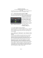
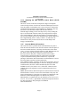
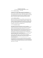
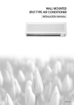
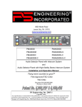
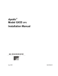
Apolloâ
Model SL10 Series
Audio Selector Panel
User’s Guide
December 2001
560-0973-00a
No part of this document may be reproduced in any form or by any
means without the express written consent of UPS Aviation
Technologies, Inc.
UPS Aviation Technologies, Inc., II Morrow, and Apollo are trademarks
of UPS Aviation Technologies, Inc.
© 2001 by UPS Aviation Technologies, Inc. All rights reserved.
Printed in the U.S.A.
UPS Aviation Technologies, Inc.
2345 Turner Road, S.E. Salem, OR 97302
U.S.A. Toll Free
800.525.6726
Canada Toll Free
800.654.3415
International
503.391.3411
FAX
503.364.2138
Visit our web page at http://www.upsat.com
Send comments about this manual by email to: [email protected]
History of Revisions
Original Release December 2001 Rev. 00
Ordering Information
To receive additional copies of the Apollo SL10 Installation Guide, order
part #560-0978-00 and for the Apollo SL10 User’s Guide, order part
#560-0973-00a.
UPS Aviation Technologies
SL10 Series Audio Selector Panel and Intercom System
User’s Guide
Table of Contents
Section I - General Information ...................................................... 1
1.1 SCOPE ...................................................................................... 1
1.2 Audio Selector (All models) ..................................................... 1
1.2.1
Speaker Amplifier ........................................................... 2
1.3 Mic Selector Switch (Fail Safe Operation) ............................... 2
1.3.1
Swap Mode (Switch from Com 1 to Com 2 remotely).... 3
1.4 Split Mode................................................................................. 3
1.5 Intercom .................................................................................... 3
1.5.1
Volume Control, Monaural (SL10M SL10) .................... 3
1.5.2
Volume Control, Stereo, (SL10S, SL10MS) ................... 4
1.5.3
Adjusting the VOX-Squelch control, Monaural (SL10,
SL10M) 4
1.5.4
Adjusting the VOX- Squelch control, Stereo (SL10S,
SL10MS)........................................................................................ 5
1.5.5
Intercom Modes (All versions)........................................ 5
1.5.6
Push to talk intercom mode ............................................. 7
1.6 Marker Beacon (SL10M, SL10M-S.......................................... 8
1.6.1
Middle Marker Sense ...................................................... 8
1.6.2
External Marker Lights (SL10, SL10S)........................... 8
1.6.3
Receiver Sensitivity......................................................... 9
Section II- Warranty and Service ................................................. 10
2.1 Warranty ................................................................................. 10
2.2 Factory Service ....................................................................... 10
UPS Aviation Technologies
SL10 Series Audio Selector Panel and Intercom System
User’s Guide
UPS Aviation Technologies
SL10 Series Audio Selector Panel and Intercom System
User’s Guide
Section I - General Information
1.1
SCOPE
This section provides detailed operating instructions for the UPS
Aviation Technologies SL10, SL10S, SL10M, SL10M-S, SL10C,
SL10S-C, SL10M-C, and SL10M-S-C Audio Selector Panel/Intercom
Systems. Please read it carefully before using the equipment so that you
can take full advantage of its capabilities.
This section is divided into four sections covering the basic operating
areas of the SL10 systems. They are: Audio Selector, Transceiver
Selection, Intercom, and Marker Beacon Receiver (SL10M and SL10MS
only).
1.2
Audio Selector (All models)
Through the use of two
momentary and seven latched,
push-button, back-lit switches, it is
possible to select any or all
receiver audio. C1 and C2 are
momentary switches.
When selected, an internal
backlight will illuminate
indicating which audio source is
selected. Because the rotary switch
Figure 1 Audio Selector
controls what transceiver is being
heard by the pilot and copilot (the crew), "Cl" (Com 1) and "C2" (Com 2)
push-buttons are of the momentary type and do not remain in when
selected. This is also part of the "auto function." You will always hear the
audio from the transceiver that is selected by the rotary mic selector
switch.
The users can identify which receivers are selected by noting which
push-button switches are illuminated. Push buttons labeled Nl (Nav 1),
N2 (Nav 2), D (DME), M (Marker), A (ADF), AX (auxiliary), and S
(Speaker) are "latched" type switches. When one of these buttons is
pressed, it will stay in the "in" position. Press the switch again and it be
in the "out" position and remove that receiver from the audio. While
selected, the switch will also be annunciated by an internal lamp.
NOTE: In Split Mode, no pushbuttons will be active. The only audio
selected is the com 1 and 2, as indicated by their respective lamps.
Page 1
UPS Aviation Technologies
SL10 Series Audio Selector Panel and Intercom System
User’s Guide
1.2.1 Speaker Amplifier
The "S" in the push-button section stands for speaker. This switch will
place all selected audio on the cockpit speaker when this switch is
selected. NOTE: with the exception of unswitched unmuted inputs
(Altimeter warning), the speaker amplifier is not active in the "Split
Mode." To reduce power consumption and internal heat buildup in the
avionics stack, switch off the speaker amplifier when not in use.
1.3
Mic Selector Switch (Fail Safe Operation)
Unit power is turned on and off by the Mic
selector switch. In the OFF or "FAIL-SAFE"
position, the pilot is connected directly to Com
1 allowing transmit and receive capability
regardless of unit condition. Any time power is
removed or turned OFF, the audio selector will
be placed in the fail-safe mode. The first
position clockwise from OFF is COM 1. Both
pilot and copilot will be connected to the Com
Figure 2
l transceiver. While in the COM 1 or COM 2
Mic Selector
mode, the intercom functions normally. Both
the pilot and copilot have transmit capabilities
on the selected transceiver. All hear the selected audio if the intercom is
in the ALL mode. Only the person who presses their Push To Talk (PTT),
will be heard over the aircraft radio. Turning the rotary switch to the
COM 2 position will place pilot and copilot on Com 2.
The SL10-Series has an automatic selector mode. Audio from the
selected transceiver is automatically heard in the headsets and speaker
(when selected). You can check this function by switching from COM 1
to COM 2 and watch the selected audio light on the selector change from
C1 to C2. This ensures the pilot will never transmit on a radio is not
listening to.
In SL10-series units, Serial Number T03092 and above, when switching
the mic selector rotary switch from COM 1 to COM 2, while COM 2 audio
had been selected, Com 1 audio will continue to be heard. This
eliminates the pilot having to switch Com 1 audio back on, if desired.
When switching from COM 1 to COM 2 while Com 2 has NOT been
selected, Com 1 audio will be switched off. In essence, switching the mic
selector will not effect the selection of Com audio.
Important: When the mic selector is in the full counter clockwise
position, the SL10 power is removed, and it is in the FAIL-SAFE mode.
The pilot headset and microphone is connected directly to Com 1.
Page 2
UPS Aviation Technologies
SL10 Series Audio Selector Panel and Intercom System
User’s Guide
1.3.1 Swap Mode (Switch from Com 1 to Com 2 remotely)
With a yoke mounted, momentary switch, the pilot can change from the
current Com transceiver to the other by depressing this switch. When
"Swap Mode" is active, an LED annunciator will illuminate, indicating
that the Mic Selector switch position is no longer valid. To cancel "Swap
Mode," the pilot may either press the yoke mounted switch again, or turn
the Mic Selector Switch to the Com that is active.
1.4
Split Mode
Turning the rotary switch to COM 1/COM 2 places the SL10 into "Split
Mode". This places the pilot on Com 1 and the copilot on Com 2. Pilot
and copilot are isolated from each other on the intercom, but can use their
respective radios simultaneously. An example of this useful feature is
when the pilot may want to talk to Air Traffic Control, while the copilot
may be speaking to Flight Watch.
The "Split Mode" radio selection can be reversed by switching to COM
2/COM l. The pilot will be on Com 2 and the copilot will be on Com 1. A
third "Split Mode" selection is TEL/COM l. This will place the pilot on
airborne radiotelephone, HF or other transceiver (if installed), while the
copilot will be on Com 1.
Note: In all SL10s, Split Mode turns off all other (Nav, ADF,
etc.)selected audio to pilot and copilot. Additionally, there is no
intercom function between pilot and copilot. Passengers still have
intercom capability among themselves.
1.5
Intercom
1.5.1
Volume Control, Monaural (SL10M SL10)
The pilot volume control knob
adjusts the loudness of intercom
and music in the pilot’s
headphones only. It has no
effect on selected radio audio
levels. The copilot volume
control adjusts the loudness of
the intercom and music in the
copilot headset only. The
passenger volume is factory set
Figure 3 Volume Controls Mono at a comfortable level. This is a
service adjustment that can be
Page 3
UPS Aviation Technologies
SL10 Series Audio Selector Panel and Intercom System
User’s Guide
accessed by the avionics technician. Most general aviation headsets have
a built-in volume control, so volume can be adjusted “locally.”
1.5.2 Volume Control, Stereo, (SL10S, SL10MS)
The volume control knob adjusts the loudness of the intercom and music
for the pilot and copilot only. It has no effect on selected radio levels or
passengers' level. The passenger
volume level is factory set for a
comfortable listening level. Most
general aviation headsets today
have a built-in volume controls,
therefore, volume can be adjusted
at the headset. There is a service
adjustment that can be accessed by
Figure 4 Volume Control Stereo
the avionics technician. This will
allow adjustment of the
passenger's volume for a
comfortable listening level.
1.5.2.1 Mono headsets in Stereo Installation
All passenger headsets are connected in parallel. Therefore, if a monaural
headset is plugged in to a SL10 Stereo installation, one channel will be
shorted. Although no damage to the unit will occur, all passengers will
lose one channel.
1.5.3 Adjusting the VOX-Squelch control, Monaural (SL10,
SL10M)
The SL10 provides adjustable VOX squelch controls for the pilot and
copilot (the copilot's VOX control also adjusts the passengers VOX
squelch) Since the number of microphones open at any one time is
reduced, the amount of background noise is diminished. This also allows
the use of dissimilar headsets with the same intercom. The user can
adjust the trip level of the VOX to fit the individual's voice and mic,
which helps eliminate the frustration of clipping the first syllables.
With the engine running, set the VOX control knob by slowly rotating
the SQL control knob clockwise until you no longer hear the engine noise
in the headphones. When the microphone is positioned properly near
your lips, normal speech levels should open the channel. When you have
stopped talking, there is a delay of about ½ second before the channel
closes. This helps prevent choppy communications.
Page 4
UPS Aviation Technologies
SL10 Series Audio Selector Panel and Intercom System
User’s Guide
1.5.4 Adjusting the VOX- Squelch control, Stereo (SL10S,
SL10MS)
The stereo versions of the SL10 incorporate a single VOX Squelch
control for all positions. Like all UPS Aviation Technologies intercoms,
since the number of microphones active at any one time is reduced, the
unwanted background noise in the headphones is diminished. This also
allows the use of dissimilar headsets with the same intercom.
With the engine running, set the VOX trip level by slowly rotating the
SQUELCH control knob clockwise until you no longer hear the engine
noise in the headphones. When the microphone is positioned properly
near your lips, normal speech levels should open the channel. When you
have stopped talking, there is a delay of about ½ second before the
channel closes. This prevents closure between words and prevents
choppy communications.
1.5.5 Intercom Modes (All versions)
The center switch is a 3-position mode switch that allows the pilot to
tailor the intercom function to best meet the situation. The description of
the intercom mode function is valid only when the unit is either in the
COM 1 or COM 2 position of the Mic Selector switch. When the unit is in
the "Split" mode, only the passengers have intercom function.
ISO: (Up Position): The pilot is isolated from the intercom and is
connected only to the aircraft radio. He will hear the aircraft radio
reception (and sidetone during radio transmissions). Copilot and
passengers will hear the intercom and music on Entertainment 1, but not
the aircraft radio receptions or pilot transmissions.
ALL: (Middle Position): All parties will hear the aircraft radio, intercom,
and music from entertainment input #1. However, during any intercom
communications, the music volume automatically decreases when
SoftMute is active (See section 3.6.5.1). The music volume increases
gradually back to the original level after communications have been
completed.
CREW (Down Position): Pilot and copilot are connected on one intercom
channel and have exclusive access to the aircraft radios. They may also
listen to Entertainment 1. Passengers can continue to communicate with
themselves without interrupting the Crew and also may listen to
Entertainment 2. Anytime the SL10 is in either the COM 1/COM 2, COM
2/COM 1, or TEL/COM 1, ("Split Mode") the pilot and copilot do not have
any intercom function. The passengers will maintain
intercommunications.
Page 5
UPS Aviation Technologies
SL10 Series Audio Selector Panel and Intercom System
User’s Guide
1.5.5.1 Soft Mute (Mono)
Soft Mute must be enabled during installation by jumpering top
connector pins 12 and N. A SPST switch can be installed between these
pins for a pilot selectable mute mode. Without this connection, music is
not muted during intercom activation. This “Karaoke Mode” prevents the
music muting when a sing-along is desired. "Soft Mute" mode only
applies to entertainment input #1. Entertainment #2 does not mute.
1.5.5.2 Soft Mute (Stereo)
Both entertainment devices have the "Soft Mute" mode. In units earlier
than a “G” intercom board serial number (second set of numbers), only
entertainment input #1 has the mute inhibit capability. "Soft Mute" mode
for the Crew positions (Entertainment 1) can be selected by pressing in
the Volume control knob once. In later units the SQL knob controls the
Soft Mute of the passengers entertainment (#2).
1.5.5.3 Entertainment Input
The audio selector panel has provisions for up to two separate
entertainment input devices. Which device is heard is determined by the
position of the three position mode switch located in the center of the
intercom section of the audio panel. (See Table 3-1 for overview.)
While in the ISO (Isolate) mode, only the copilot and the four passengers
will hear entertainment device #1. In normal operation, whenever a
person speaks or if the aircraft radio becomes active, the music will
automatically mute and then will gradually return to the original listening
level when the intercom or radio activity ceases.
Which entertainment device will be heard is determined by the mode
selector switch. When in the ALL mode, all parties will hear the
entertainment input #1. While in the CREW mode, pilot and copilot will
hear entertainment input #1 while the passengers may listen to
entertainment input #2.
It is also possible to use only one entertainment input device for both
entertainment inputs. It is suggested however, that a switch (DPDT) be
installed between the single entertainment device and entertainment input
#1. This will allow the pilot and copilot decide if they hear entertainment
while in the Crew mode.
Page 6
UPS Aviation Technologies
SL10 Series Audio Selector Panel and Intercom System
User’s Guide
Table 1 Intercom Modes
Mod
e
Isola
te
Pilot
Hears
A/C Radio
Pilot
Sidetone
(during
radio
transmissi
on)
Copilot Hears
Passenger Hears
Comments
Copilot and
passenger
intercom
Entertainment #1
Passenger and
Copilot intercom
Entertainment #1
All
Pilot
Copilot
A/C Radio
Passenger
s
Entertainm
ent #1
Copilot
Pilot
A/C Radio
Passengers
Entertainment #1
Passengers
Pilot
Copilot
A/C Radio
Entertainment #1
Crew
Pilot
Copilot
A/C Radio
Entertainm
ent #1
Copilot
Pilot
A/C Radio
Entertainment #1
Passengers
Entertainment #2
This mode allows
the pilot to
communicate
with the ground
without the
copilot or
passengers
bothered by the
conversations.
Copilot and
passengers can
continue to
communicate
and listen to
music
This mode allows
all on board to
hear radio
reception as well
as communicate
on the intercom.
Music and
intercom is
muted during
intercom and
radio
communications
A second music
source is
automatically
enabled for the
passengers.
1.5.6 Push to talk intercom mode
SL10-series audio selector/intercom systems with serial number
beginning with the letter “M” (monaural version) or “G” (stereo version).
In some extremely high noise environments, it may be desirable to have a
push to talk (PTT) intercom, instead of relying on voice-activation
(VOX).
In SL10 series with later configuration boards, the PTT intercom
capability is added. To operate the PTT, simply rotate the SL10 squelch
control to maximum (fully CW). Grounding the appropriate pin on the
top connector through a momentary switch will open only that intercom
channel. The pilot and copilot are individually. All passenger mics are
controlled with pin 20.
Page 7
UPS Aviation Technologies
SL10 Series Audio Selector Panel and Intercom System
User’s Guide
The same pins are used for both mono and stereo SL10 Systems. This
applies ONLY to units with applicable serial numbers.
1.6
Marker Beacon (SL10M, SL10M-S
The optional Marker Beacon Receiver uses visual and audio indicators to
alert you when the aircraft passes over a 75 MHz transmitter.
The Blue lamp, labeled "O," is the Outer Marker lamp and has an
associated 400 Hertz 'dash' tone. The lamp and tone will be keyed at a
rate of two tones/flashes per second when the aircraft is in the range of
the Outer Marker Beacon.
The Amber lamp, labeled "M," is the Middle Marker lamp and is coupled
with a 1300 Hertz tone. It is keyed alternately with short 'dot' and long
'dash' bursts at 95 combinations per minute.
The White lamp, labeled "A," is the Airway/Inner marker and has a 3000
Hertz 'dot' tone. The lamp and tone will be keyed at a rate of six times
per second.
The audio from the Marker Beacon Receiver can be heard by selecting
the "M" push-button switch. To adjust the volume level, there is a service
adjustment located on the top of the unit. See Section 2.5
A 3-position switch is used to set the receiver sensitivity and to test the
indicator lamps. Use "HIGH" sensitivity initially. This allows you to hear
the outer marker beacon about a mile out. Then select the “LOW”
sensitivity to give you a more accurate location of the Outer Marker. The
momentary down switch position is labeled "TEST" and illuminates all
three lamps simultaneously to assure the lamps are in working order.
Upon first application of power to the unit, the Marker enters a self test
mode. The flickering blue marker light indicates a test in process. If the
test continues for more than 10 seconds, or the lamps do not extinguish,
return the unit for service.
1.6.1 Middle Marker Sense
A Middle Marker sense output signal is available to automatically reduce
the autopilot sensitivity after the aircraft has passed over the Middle
Marker. This function will not operate during the test mode. This output
will go to +4.75 VDC (± 0.25 VDC) when a valid Middle Marker signal
is received.
1.6.2 External Marker Lights (SL10, SL10S)
For installations that require external marker beacon lights, there are
three outputs that can drive 12 Volt lamps only. The external output
lamps are driven high (+9 VDC ±0.5 VDC) when active. Maximum
source current per lamp is 125 mA.
Page 8
UPS Aviation Technologies
SL10 Series Audio Selector Panel and Intercom System
User’s Guide
If using an external marker receiver, the audio input is lower connector,
pin 11 (Aux. input).
1.6.3 Receiver Sensitivity
Although the SL10M meets FAA TSO-C35d sensitivity specifications,
the sensitivity of the receiver has been adjusted to meet real world
requirements (150mV and 1400mV Soft). This will usually eliminate the
need for the avionics shop to reduce the sensitivity in the field so as to
prevent early detection of the marker beacons. If your particular
installation requires more or less sensitivity, please call the factory for
details on how to adjust the receiver sensitivity in the field.
Page 9
UPS Aviation Technologies
SL10 Series Audio Selector Panel and Intercom System
User’s Guide
Section II- Warranty and Service
2.1
Warranty
In order for the factory warranty to be valid, the installations in a
certified aircraft must be accomplished by an FAA- certified avionics
shop and authorized UPS Aviation Technologies dealer. An FAA Form
337 must also be accompanied by the warranty card for this warranty to
be in effect. If the unit is being installed by in an experimental aircraft
by the owner/builder, a factory-made harness must be installed for the
warranty to be valid.
UPS Aviation Technologies, Inc. warrants this product to be free from
defect in material and workmanship for a period of three (3) years from
the date of installation (on units shipped after Jan 1, 1999). During the
first twelve (12) months of this three-year warranty period, UPS Aviation
Technologies, Inc., at its option, will send a replacement unit at our
expense if the unit should be determined to be defective after
consultation with a factory technician. In the following twenty-four (24)
months the unit must be returned to UPS Aviation Technologies, or a
certified UPS Aviation Technologies Service Center, for repairs.
This warranty is not transferable. Any implied warranties expire at the
expiration date of this warranty. UPS Aviation Technologies SHALL
NOT BE LIABLE FOR INCIDENTAL OR CONSEQUENTIAL
DAMAGES. This warranty does not cover a defect that has resulted from
improper or unreasonable use or maintenance as determined by us. This
warranty is void if there is any attempt to dissemble this product without
factory authorization. This warranty gives you specific legal rights, and
you may also have other rights which may vary from state to state. Some
states do not allow the exclusion of limitation of incidental or
consequential damages, so the above limitation or exclusions may not
apply to you.
2.2
Factory Service
The unit is covered by a 26-month limited warranty. See warranty
information. Call UPS Aviation Technologies, Inc. at (800) 525-6726
before you return the unit. This will allow the service technician to
provide any other suggestions for identifying the problem and
recommend possible solutions. After discussing the problem with the
technician and you obtain a Return Authorization Number, ship the
product to:
UPS Aviation Technologies, Inc.
2345 Turner Road, S.E.
Salem, OR 97302
U.S.A. Toll Free 800.525.6726
Page 10
560-0973-00a
December 2001