1
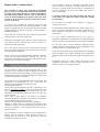
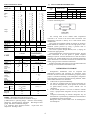
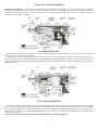
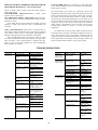
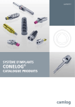
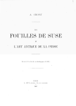
Installation, Start- Up And Service Instruction 30HR-HS 040, 050, 060 Reciprocating Liquid Chillers 30HR-HS 040 Model C and 30HR-HS 050,060 Model B INSTALLATION LOCATION Accessory steel manifold packages for inlet and outlet condenser water are available for 30HR units. Each manifold is furnished in two sections, to be field welded as shown in Fig. 1 Manifolds should not be used where regulating valves are required because separate valves must be used on each condenser circuit. Set water-regulating valve to maintain design head pressure. Do not adjust to compensate for high head pressures caused by fouled condenser tubes, excess refrigerant or the presence of non-condensable. Due to changes in water temperature, it may be necessary to adjust the valve seasonally, After adjusting for design head pressure, shut unit down. Water regulating valve should shut off flow of water in a few minutes. If it does not, it will be necessary to raise the head pressure setting. Make sure that capillary tube from each water-regulating valve is connected to the proper condenser purge valve. Condenser water must enter at bottom for proper operation Units should not be stored where exposed to the weather because of the sensitive control mechanisms and electrical devices. Locate unit indoors. See Fig. 1 and Table 1 for door clearances and space requirements. Provide clearances at one end for removal of tubes (Fig. 1, callouts 7 and 8). Floor must be strong enough to support to operating weight. If necessary, add supporting structure (steel beams or reinforced concrete slab) to floor to transfer weight to nearest beam(s). All units have spring vibration isolators and mufflers. Interconnecting piping must be flexible enough to prevent vibration transmission. If vibration still exists, use isolators on unit itself. If unit is installed on upper floor where vibration cannot be transmitted to ground, use field-purchased vibration mountings under each mounting hole. Back off mounting lock bolts to allow compressor to float freely: otherwise, excessive vibration will result. Move unit on its skid to final location. If using chain hoist, use a spreader bar so that control boxes will not be damaged by sling. Place sling under skid. Do not attach sling to piping or component. Move unit in upright position: lower gently from truck or rollers. Use enough pipes to support skid when rolling. Figure 1 shows location mounting holes. Areas where corners will be located must be level before unit is placed. Level unit with spirit level on frame channels. Bolt unit to floor (recommended for basement or ground floor installations that transmit vibration to ground without affecting building structure). See Table 2 for weight distribution. of the internal sub cooler in the bottom of the condenser (Fig. 1). CAUTION: Retighten all condenser head bolts before filling system with water. Discharge pipe from high side pressure relief valve (HR units) must not be smaller than valve size. HS units require fieldinstalled high side pressure relief valve near condenser in each refrigerant circuit. Most local codes require piping from valve to outdoors. Water leaving condenser is under pressure and should not be connected directly into sewer lines. Check local codes. A 3/8-in. drain plug is located at each end of each condenser. NOTE: provide means for draining system in winter and for repairs. CONDENSER Two check valves and two pressure relief valves are shipped loose with each condenser less (HS) unit as standard equipment, Install one of each in the discharge line of each refrigerant circuit, downstream of the hot gas muffler. Locate the relief valve close to remote condenser. There must be no shutoff device between relief valve and condenser; Installation of these valves must be in compliance with all applicable codes Run water supply lines as short as possible. Size lines according to head pressure available (not necessarily connection size), especially on cooling tower application. See system Design Manual, Part 3, Piping Design. For installation requiring a water regulating valve, a separate valve is required (not supplied by carrier) for each refrigerant circuit. Water regulating valve must be installed on cooling tower application where low outdoor ambient affect head pressure. The 30HS unit using air-cooled or evaporative condensers should have adequate means for head pressure control when operating below 60 F outdoors ambient. 1 Do not attempt to repair or recondition any safety devices when corrosion or build-up of foreign material (rust, dirt, scale, etc.) is found within the valve body or mechanism. If necessary, replace the device. Do not install safety valves in series or backwards. Repair safety consideration The personnel in charge must maintain all installation parts, in order to avoid material deterioration and injuries to people. Faults and leaks must be repaired immediately. The authorized technician must have the responsibility to repair the fault immediately. Each time repairs have been carried out to the unit; the operation of the safety devices must be re-checked. CAUTION: Do not step on refrigerant lines. The lines can break under the weight and release refrigerant, causing personal injury. Do not climb on a machine. Use a platform, or staging to work at higher levels. If a leak occurs, evacuate all refrigerant, repair the leak detected and recharge the circuit with the total R407C or R22 charge, as indicated on the unit name plate. Only charge liquid refrigerant R407C or R22 at the liquid line (see chapter " Refrigerant charge ".) Use mechanical lifting equipment (crane, hoist, winch, etc.) to lift or move heavy components. For lighter components, use lifting equipment when there is a risk of slipping or losing your balance. Ensure that you are using the correct refrigerant type before recharging the unit (see unit name plate). Use only original replacement parts for any repair or component replacement. Consult the list of replacement parts that corresponds to the specification of the original equipment. Charging any refrigerant other than the original charge type will impair machine operation and can even lead to a destruction of the compressors. Do not drain water circuits containing industrial brines, without informing the technical service department at the installation site or a competent body first. Do not use oxygen to purge lines or to pressurize a machine for any purpose. Oxygen gas reacts violently with oil, grease, and other common substances. Close the entering and leaving water shutoff valves and purge the unit hedonic circuit, before working on the components installed on the circuit (screen filter, pump, water flow switch, etc.). Never exceed the specified maximum operating pressures. Verify the allowable maximum high-and low side lest pressures by checking the instructions in this manual and the pressures given on the unit nameplate. Periodically inspect all valves, fittings and pipes of the refrigerant and hedonic circuits to ensure that they do not show any corrosion or any signs of leaks. Do not use air for leak testing. Use only refrigerant or dry nitrogen. Do not unwed or flame cut the refrigerant lines or any refrigerant circuit component until all refrigerant (liquid and vapor) has been removed from chiller. Traces of vapor should be displaced with dry air nitrogen. Refrigerant in contact with an open flame produces toxic gases. The necessary protection equipment must be available, and appropriate fire extinguishers for the system and the refrigerant type used must be within easy reach. Do not siphon refrigerant. Avoid spilling liquid refrigerant on skin or splashing it into the eyes. Use safety goggles. wash any spills from the skin with soap and water . If liquid refrigerant enters the eyes, immediately and abundantly flush the eyes with water and consult a doctor. Never apply an open flame or live steam to a refrigerant container. Dangerous overpressure can result. If it is necessary to heat refrigerant, use only warm water. Do not re-use disposable (non-returnable) cylinders or Attempt to refill them. It is dangerous and illegal. When cylinders are empty, evacuate the remaining gas pressure, and move the cylinders to a place designated for their recovery. Do not incinerate. Do not attempt to remove refrigerant circuit components or fittings, while the machine is under pressure or while it is running. Be sure pressure is at 0 KPa before removing components or opening a circuit. 2 15 N M L MTG HOLE C L P REFRIG INLET REFRIG DISCHARGE 17 K 1'-6 1 4 " CL 1'-7" CL 2'-1 5 8" MTG HOLES 16 30HS TOP VIEW 30 30HS END VIEW MTG HOLE 8 3 1'-3 4 " BOTH ENDS 27 28 29 6'-5 3 4 " 5 J 9 10 3 4 " DIAM 18 CL CONDENSER 10" 2'-6 3 4 " 1'-5" H 1'-0 3 16 " CL 3'-0" MTG HOLES 1'-1 1 4 " 10 F 13 12 7 30HR TOP VIEW 11 30 4'-1 1 2 " START BUTTON STOP BUTTON 21 G 1'-1 3 8" 30HR END VIEW 9'-0 3 8" 23 22 26 25 6 WATER OUT WATER IN CONTROL PANEL 20 FIELD WELDED 2'-11 3 4 " 24 2'-7 1 8 " E DIAM C L COOLER ACCESSORY WATER MANIFOLDS AND CONDENSER NOZZLE ARRANGEMENT VIEWED FROM FRONT OF UNIT. 2 30HR , HS FRONT VIEW 4 3 C 1 INLET D C 4'-6 1 2 " CL MTG HOLES B A LEGEND 1 – 3-in FPT Water inlet 12 – Cut hole in removable plate for power inlet 2.1/2-in max conduit size – Unloaded Solenoid. One on each compressor 2 – Temperature Controller Bulb 13 3 – 3 in FPT Water Outlet 14 – Oil safety Switches. Manual reset 4 – 1-in FPT Water Drain Conn. 15 – 7/8-in ODF Refrigerant Liquid Inlet from 22 – Compressor no. 1:6 cylinder for 040, 050 and 060 23 – Compressor no 2:4 cylinder for 040, 050, 6-cylinder for 060 24 –Liquid Line Solenoid Valve (one each CKT) (Std equipment on HS. accessory on HR) 16 condenser circuit no. 1 – 7/8-in ODF Refrigerant liquid Inlet from condenser circuit no. 2 – 1.3/8-in ODF Discharge Line. Circuit 1 and 2 6 – 1/4-in SAE Flare Field Charging Valve (2) 17 7 – Space 18 – Replaceable core Filter Driers, one each required to remove cooler tubes (either end) 8 – Space required to remove condenser tubes (either end) 9 – 2.1/2 - in diameter SCH 40 removable nozzles (each end of both condensers) 10 – Low Water Temp Cutout Bulb 1 –Three 7/8-in knockouts. Two on top and one on back of control box circuit. HR, HS040 one core each HR HS050 two cores circuit 1,one core circuit 2 HR HS060 2 cores each 25 – Water inlet Manifold (accessory) 4-in 150 lb ASA flat-face flange (accessory) 4-in 150-ib ASA flat-face flange – 5/8-in SAE Flare Pressure Relief Valve (each condenser) – 1/4-in Flare Conn. for water reg. valve (each condenser) 26 – Water Outlet Manifold 27 28 19 – Compressor Sequence Switch 29 – 1/4-in Purge Valve (each condenser) 20 – Circuit Breakers 21 – Gage Panel (accessory) both sides 30 – Field Installed Control Transformer Fig. 1 – Dimensions 3 (accessory). (In control panel, adjacent to main terminal (block.) Table 1-PHYSICAL DATA HR040 Table 2-WEIGHT DISTRIBUTION HS040 HR050 HS050 HR060 HS060 UNIT 30 UNIT 30 DIM. (Ft-in)* (Refer A 7– 6 To B 1– 5 Fig. 1) C 0– 10 D 0– 4 3 E 0– 10 3 F 7– 0 1 G 0– 5 1 H 0– Comp 2 9 0– 6 J Comp 1 3 9– 0 1 2– 2 7 1– 6 1 4 1– 1 3 4 1– 0 3 2 9– 3 1 2 0– 4 1 1 4 0– 10 1 8 0– 6 1 4 7 K – 3– 8 3 K – 3– 8 3 L – 1– 4 3 M – 1– 5 5 N – 0– 5 1 P – 0– 5 1 2640 NET WT (lb) REFRIG R407C CHG (lb) † TOTAL OIL CHG (L) CONDENSERS 09RP022 09RP027 Length (ft - in) Number Area ( sq ft ) Inside Outside SUBCOOLER TUBES Length (ft-in) Number Area (sq ft) Inside Outside NO. CIRCUITS NO. PASSES 7 4 1– 6 1 4 1– 1 3 4 1– 0 3 2 9– 3 1 2 0– 4 1 4 0– 10 1 4 0– 6 1 – 3– 8 3 – 1– 1 3 – 1– 3 5 – 0– 11 3 – 0– 11 3 1740 3065 2115 40 84‡ 8 8 8 2 2 13.24 4 8 8 8 4 4 49 – – – 1 1 4 – – 3– 9 1 – 1– 3 5 – 1– 3 5 – 0–11 3 – 0–11 3 3180 2180 Location of mounting holes: 4 4 8 8 The sensing bulb of the chilled water temperature controller is in a well in the return water connection. The temperature controller is factory set to control from return chilled water. Plan piping for minimum number of changes in elevation. Install manual or automatic vent valve at high points in line. Maintain system pressure by using a pressure tank or combination relief and reducing valve. See Carrier System Design Manual, Part 3, Piping, for chilled water piping details. Install thermometers in entering and leaving lines. Provide drain connections at all low points to permit complete drainage of system. Connect shutoff valve to drain line before operating unit. Install shutoff valve near entering and leaving water connections. Use flexible connections on condenser and cooler piping to reduce vibration transmission. Insulate piping after leak testing to prevent heat transfer and sweating. Cover insulation with moisture seal. 4 4 56 – – 09RP027 30HR 050, 060 5– 10 OD Fins, 40/ in. 5– 10 1 4 129 36 44 – – 273 273 36.0 117 44.8 145 – 5– 10 1 REFRIGERANT CHARGE Refrigeration installations must be inspected and maintained regularly and rigorously by specialists. Their activities must be overseen and checked by properly trained people. To minimize discharge to the atmosphere, refrigerants and Lubricating oil must be transferred using methods, which reduce leaks and losses to a minimum. Leaks must be repaired immediately All units are equipped with two special connections on the suction and liquid line, which permit the connection of quick-connect recovery valves without loss of refrigerant. If the residual pressure is too low to make the transfer alone, a purpose-built refrigerant recovery unit must be used. Compressor lubricating oil contains refrigerant. Any oil drained from a system during maintenance must therefore be handled and stored accordingly. Refrigerant under pressure must never be discharged to the atmosphere 4 – – – – 4 13 2 (refrig) 4 (refrig) 3 (water) 5 – CONNECTIO (in) REFRIG Liquid (2) 1 1 Suction (2) 2 1 MDWP (psig) Water side Refrig side 8 ODM (See Fig. 1) 8 ODM – 250 235 B 475 590 610 4 – 4 HS A 475 590 610 4 2 3 HR A B 970 490 1150 580 1200 600 2 1 040, 050 HS 1900 2360 2440 2 – 09RP022 HR 2920 3460 3590 LOAD PER MTG HOLE (lb) 4 CONDENSER Prime Surface 6– 2 1 2 6– 10 1 2 129 4 18 6– 8 1 2 4 4 3– 9 87‡ 040 050 060 8 – 15.6 2 1 2– 2 1 71‡ 6– 0 8 3– 9 30HR, 30HS 040 050, 060 SHELL Length (ft - in) TUBES 1 – 8 COOLER UNIT 4 9– 0 APPROXIMATE OPER WT (lb) 250 385 MDWP–– Maximum Design Working pressure * Dimensions common to all units are shown in Fig 1. † HR units have operating charge. HS units have holding charge (for operating charge, add listed HS charge to field piping and remote condenser charges). ‡ In condenser when shipped; between liquid valve and compressor discharge valve 4 Recharging liquid refrigerant NOTE: Use only oils, which have been approved for the compressors. Never use oils, which have been exposed to air. CAUTION:HR units are charged with liquid R22 refrigerant. NOTE: Regularly carry out leak checks and immediately repair any leak found. Recommended Oils: R407C compressors: - Carrier specification: PP 47 26 - Mobile oil EAL 68 (original charge) R22 compressors: - Mineral oil, Carrier specification: pp 3326 -Gargoyle Artic (Mobil Oil, original charge) - Suniso 3 GS (Sun Oil Co.) Undercharge If there is not enough refrigerant in the system, this is indicated by gas bubbles in the moisture sight glass. CAUTION: R407C oils are absolutely not compatible with R22 oils. If the undercharge is significant, large bubbles appear in the moisture sight glass, and the suction pressure drops. The compressor suction superheat is also high. The machine must be recharged after the leak has been repaired. Find the leak and completely drain the system with a refrigerant recovery unit. Carry out the repair, leak test and then recharge the system Table 3-ELECTRICAL DATA COMPLETE UNIT AND COMPRESSORS VOLTS UNIT 30 * 230 MKW WSA 400 ICI WSA ICF ICI 319 355 355 319 355 355 81 83 97 90 98 117 234 234 248 238 238 257 205 205 205 205 205 205 MTA FLA LRA MTA 69 80 106 80 120 29 33 43 33 52 110 144 205 144 205 41 46 60 46 73 ICF IMPORTANT: After the leak has been repaired, the circuit must be tested, with out exceeding the maximum low-side operating pressure shown on the unit nameplate. 040 050 060 040 HS 050 060 COMP R 06E 43.5 44.2 53.6 49.6 50.9 61.12 150 250 275 250 275 17.4 20.0 26.8 20.0 30.9 HR The refrigerant must always be recharged in the liquid phase into the liquid line. The refrigerant cylinder must always contain at least 10% of its initial charge. CAUTION: R407C Oils are absolutely not compatible with R22 oils. HR HS OIL CHARGE KW 138 144 171 156 165 194 FLA 49 57 76 57 86 368 404 431 376 412 441 LRA 191 250 255 250 355 Table 4-COMPRESSOR 06E USAGE† All units are factory charged with oil. If oil is visible in sight glass, start compressor. Observe level and add oil, if required, to bring Level in Crankcase to middle of bull , s-eye during steady operation. To add or remove oil see Standard Service Techniques Manual, Chapter 1, Refrigerants. NOTE: To ensure trouble-free operation, use only Recommended oil, see below Do not reuse oil that has been drained out, or oil that has been left open to the atmosphere. UNIT 30 040 050 060 HS HR Circuit and Compressor Numbers 1 2 1 2 B250 B150 B250 B250 J275 B150 J275 B250 J275 J275 J275 J275 Full Load Amps Maximum Instantaneous Current Flow (amps) during starting (sum of LRA for last compressor to start plus FLA for all other running compressors). Maximum Incremental Current Inrush (amps) during ICI starting (LRA for largest compressor in unit). Maximum Input Power (each compressor). KW Locked Rotor Amps LRA Maximum Unit Input Power MKW Must Trip Amps MTA Wire Sizing Amps per NEC, Section 430-24 WSA * Suitable for use on electrical systems where voltage supplied to unit terminals is not below or above the following limits: Max 264 volts, min 198 volts for 230 – volt units. Max 457 volts. Min 342 volts for 400 – volt units. † Compressor numbered from left to right when viewed from front of unit. Each compressor has electric unloaded on one cylinder bank (2 cylinders). NOTES: 1. Compressor speed-1450 rpm. 2. Crankcase heater-180 watts, 240 volts. 3. Maximum allowable phase unbalance: volts, 2%; amps, 10% 4. Maximum incoming wire size: 350 MCM for 230-volt units; no. 0000 AWG for 400-volt units. FLA ICF To Add Oil - Close suction shutoff valve and pump down crankcase to 2 psig. (Low-pressure cutout must be jumpered.) Wait a few minutes and repeat as needed until pressure remains at 2 psig. Remove oil fill plug above bull , s-eye, add oil thru plug hole and replace plug. Run compressor for about 20 minutes and check oil level. To Remove Oil-pump down compressor to 2 psig. Loosen the 1/4- in. pipe plug in compressor base and allow the oil to seep out past the threads of the plug. The crankcase will be under slight pressure. Be careful not to remove the plug; the entire oil charge may be lost. Small amounts of oil can be removed while compressor is running thru oil pump discharge connection. The compressors installed in these units have an oil charge (91) to ensure their correct operation. Check that the oil level is between 1/8 and 3/8 up the sight glass before start-up and after normal unit operation. 5 - START-UP AND SERVICE INITIAL CHECK Crankcase heaters should be energized at all times when unit is not in operation. On 50-Hz units. Each heater is 180 watts, 240 volts. Never open any switch that will de-energize crankcase heaters unless unit is being serviced or shut down for a prolonged period. These switches include the unit field power supply switch (unless control circuit power is from separate source) and the control circuit switch or breaker. If control circuit power is from separate source, the fused disconnect must be kept closed. After a prolonged shutdown or service job, energize crankcase heaters 24 hours before starting compressors. Do not attempt to start the liquid chiller even momentarily unit the following steps have been completed. 1. Check all auxiliary components such as chilled liquid circulating pump, cooling tower if used, air handling equipment, or other equipment to which the chiller supplies liquid. Consult the manufacturer , s instructions 2. Check safety thermostat. See Safety Thermostat for adjustment. 3. Backseat (open) compressor suction and discharge shutoff valves. Close valves one turn to allow pressure to reach gages. 4. Open liquid line shutoff valves at condensers. 5. Open valves to capillaries of water-regulating valves (when used) 6. Fill chilled liquid circuit completely with clean water or other non-corrosive. fluids to be cooled. Bleed all air out of high points of system. 7. Open supply valve (or fill cooling tower if used ) for condenser cooling water. 8. Set temperature controller. 9. Check tightness of all electrical connections. 10. Check compressor oil (should be visible in bulls-eye). 11. Be sure unit is fully charged with refrigerant (see Refrigerant Charge). 12. Be sure crankcase of each compressor is warm (heaters should be on for 24 hours before starting compressors). COMPRESSOR REPLACEMENT If a replacement 6-cylinder compressor has center-bank cylinder head with discharge valve pad facing pump end, remove the head and install reverse flange head from original compressor (discharge valve pad toward motor end ). Center-bank cylinder head cannot be rotated 180 o. CIRCUIT BREAKERS One breaker for each compressor provides three-leg overload protection. Do not bypass connections or increase size of breaker to correct trouble. Determine the cause for the trouble and correct before resetting breaker. Throwing off, then on again must manually reset tripped breaker. See circuit breaker trip amps in Table 3, Electrical Data. CIRCUIT BREAKER KITE RESET START-UP Start-up should be performed only under supervision of experienced refrigeration mechanic. 1. Open all system valves that may have been closed during or after charging. 2. Check air-handling equipment, chilled water and condenser water pumps, and any other equipment connected to chiller. 3. Start unit by pushing START button. 4. Check all controls for proper operation. 5. Adjust water-regulating valve to most economical head pressure ( based on relative cost of water and electricity). 6. Check chilled water leaving temperature to see that it remains well above freezing. 7. Check compressor oil level (see Oil Charge). HIGH-LOW DUAL PRESSURE SWITCH One switch provided in each refrigerant circuit See Table 6. High-pressure switch-To check, jumper the normally -open control relay contacts. Slowly close discharge shutoff valve until compressor shuts down (should be at cutout pressure shown in Table 5). Reopen discharge shutoff valve. Compressor should start when pressure drops to cut-in point shown Low-pressure switch-To check, close suction shutoff valve and allow compressor to pump down. It should stop when suction pressure drops to cutout point shown in Table6. Compressor should restart automatically when suction pressure builds up to cut-in point shown. CRANKCASE HEATERS For winter start control where HS units are coupled with air-cooled condensers, move low-pressure switch connection from suction side of system to a pressure tap liquid line and reset to cutout at 5 psig leaving differential same (50 PSI). A 1/4in. flare connection is provided on HS units between liquid line solenoid nd TXV. Heaters are furnished on all compressors to prevent refrigerant absorption by oil in the crankcase during shutdown. Located in bottom cover of compressor, heater is held in place by clip and bracket. Make sure heater is tight to prevent it from backing out when operating. Heater will burn out if exposed to air for an extended length of time. Heater is wired into control circuit by connecting it to normally closed auxiliary contacts on compressor starter. NOTE: Check both switches at start-up and least once each year. 6 Table 5-PRESSURE SWITCH SPECIFICATIONS CUTOUT CUTIN UNIT30 Psig Kpa Psig Kpa 42±3 290±21 57±5 393±34 Low Pressure CUTOUT CUTIN High Pressure Psig Kpa Psig Kpa 280±10 1931±69 180±20 1241±138 HR 375±10 2585±69 275±20 1896±138 HS MOISTURE-LIQUID INDICATOR Clear flow of liquid refrigerant indicates sufficient charge in system. Bubbles indicate under-charged system or presence of non-condensable. Moisture, measured in parts per million (PPM), in system will change color of indicator. Green moisture is below 330 PPM: chartreuse (caution) 380 to 550 yellow (wet)- above 550 change filter-drier cores at first sign of moisture in system. Each refrigerant circuit has an indicator. With unit running, indicating element must be in contact with liquid refrigerant to give true moisture indication. 30HS units (shipped holding charge only) must be fully charged and run before moisture content can be determined. OIL PRESSURE SAFETY SWITCH Standard on 30HS units, accessory for 30HR (see Fig. 2 for wiring connections). To test, bypass pressure switch with jumper. Compressor should stop in about 120 seconds. If it continues to run for more than one minute, and nothing is wrong with the wiring, replace switch. Be sure differential switch closes when compressor stops. Switch setting requires pressure rise to 9 psig in 120 seconds and oil pressure above 4 psig for compressor operation. After test, allow 5 minutes for thermal switch to cool, then press reset button. If the safety switch stops the compressor, find trouble and correct before attempting to restart. LIQUID LINE SOLENOID VALVE One valve in each refrigerant circuit prevents liquid refrigerant from migrating to cooler during shut down. ELECTRICALLY EXPANSION VALVES These valves control flow of liquid refrigerant by maintaining constant superheat of vapor leaving cooler. Factory set to maintain a superheat of 6C; do not adjust setting unless absolutely necessary. There is one valve for each refrigerant circuit. See catalogue for more details. THERMAL EXPANSION VALVES These valves control flow of liquid refrigerant by maintaining constant superheat of vapor leaving cooler. Factory set to maintain a superheat of 8-10 F; do not adjust setting unless absolutely necessary. There is one valve for each refrigerant circuit. Fig 2-Oil Pressure Safety Switch Connection Diagram CAPACITY CONTROL COMPRESSOR THERMAL PROTECTION Capacity control is a system, which cycles compressors as well as loads and unloads cylinders in each compressor to maintain load requirements. Includes a 4-step temperature controller and two cylinder bank unloadeds. Table 6 shows capacity control steps. Four-Step Temperature Controller consists of four load switches actuated by pressures developed in a temperaturesensing bulb located in the return water nozzle of the chilled water system. The controller is factory set to control from return water temperature thru a cooling range of 10 F. The sequence switches are factory calibrated and sealed and should not require any field changes. If a different return-water cooling range or a leavingwater control is specified, or if brine is to be used the controller must be changed. Consult local Carrier representative for proper control device. The temperature at which the last step of capacity unloads indicated by the design set point on the adjustable dial (Fig. 4). Example: design set point is at 44 F. On a reduction in load, the Capacity of the unit will be reduced to zero when return water temperature drops to 44 F. WARNING: Any alteration of factory settings, except design set point, without Carrier authorization may void the Carrier Warranty. A discharge thermostat installed in one cylinder head of each compressor, senses an over temperature condition. If the discharge gas temperature of any compressor exceeds 295 5F,the thermostat opens and shuts off that compressor and the other compressor in the circuit. The thermostat reset temperature is approximately 250 F. See Fig.3 For switch connections. DT1 4 CR1 23 TB3 DT2 4 21 CR2 CI R CU IT N o.2 DT TB TB4 - Discharge Temperature Switch - Terminal Block (unit) - Terminal on unit terminal block - Terminal Connections (Marked) Fig3-Discharge Temperature Switch Connections. 7 Table 6-CAPACITY CONTROL CONTR STEPS UNIT 30HR 30HS 1 2 3 4 1 2 3 4 1 2 3 4 040 050 060 LLSV (= Open) OPERATION TRANS SW* POS1 Oper Cyl % Ck t Cap Total 1 2 TRANS SW* POS2 Oper Cyl % Ck t Cap 1 2 40 60 80 100 33 66 83 100 - 20 60 80 100 33 66 83 100 - 4 6 8 10 4 8 10 12 - 4 4 6 6 4 4 6 6 Sequence of Control-Power is supplied to Control circuit either from a separate source or thru a field-installed transformer (accessory package) with primary connected to unit power terminal block (installation instructions furnished with accessory transformer package). Control circuit is energized thru a circuit breaker on control panel. This server as ON-OFF switch for control circuit. Crankcase heaters are wired they are operative as long as control circuit breaker is on, regardless of condition of other safety devices. When a compressor stops, its heater is turned on to prevent refrigerant absorption by oil in the crankcase. Control circuit breaker should be off only when unit is being serviced. After a prolonged shutdown, energize crankcase heaters for 24 hours before starting compressors. With power to control circuit terminals 15 and 16 and control circuit breaker in "on" position, unit is ready for operation providing all safety devices are satisfied, interlocks are closed and instructions on warning labels have been followed. Total 2 2 4 4 4 6 2 6 8 10 4 8 10 12 - 4 4 6 4 4 6 2 2 4 4 4 4 6 6 LLSV – Liquid Line Solenoid Valve * Transfer Switch, manually operated. Compressor starting sequence: Pos 1, 1-2: Pos 2, 2-1. DESIGN SET POINT ADJUSTMENT Adjust set point by Rotating switch in the panel. When the START-STOP switch is turned to "Start", the panel light will come on and timer motor will start. If temperature controller is calling for cooling, No. 1 compressor will start immediately. After 15 seconds, if required by load demand, no. 2 compressor will start. At this point, timer motor will stop with timer switch contacts A-A1 and B-B1 made; temperature controller then takes over. This timer position will hold during unit operation, while temperature controller cycles compressors off and on and alternately loads and unloads cylinders in each compressor to control cooling capacity in response to load requirements. Operator should use sequence transfer switch on control panel to change lead compressor periodically: this equalizes compressor wear. A panel light for each circuit shows which compressor is running. Stop unit before changing starting sequence. 0 О C SET POINT ADJ. SET POINT L.W& SET POINT DISPLY О L.W.T 4 О 3 О 2 О 1 О SET INDICATORS Unit Stoppage (other than supply power interruption)- Watercooled (30HR) units and condenser less (30HS) units completely stop if the START-STOP switch is turned to "Stop", low water temperature cutout contacts open, contacts of any auxiliary interlock in the chilled water system open, or control circuit breaker trips. ON ON ON ON ON ON ON ON 220 SENSOR STEPS OUTPUT Fig .4 set point Adjustment Table 7– CIRCUIT DATA UNIT 30HR,HS CIRCUIT NO. Compressor No* Comp. Size (nom tons) No. Comp. Cylinders No. Comp. Unlooders† 040 1 1 20 4 1 050 2 2 20 4 1 1 1 30 6 1 060 2 2 20 4 1 1 1 30 6 1 Individual Compressor Stoppage-Motor winding thermal protector contacts open, high- or low-pressure switch 2 2 30 6 1 in the refrigerant circuit opens, oil pressure safety switch opens, or contacts of any auxiliary interlocks in refrigerant circuit open. Safety devices in one circuit do not affect operation of other circuit. A tripped main-power circuit breaker will stop the compressor in that circuit. Besides stopping compressor, the following devices close liquid line solenoid valve in each refrigerant circuit; internal motor thermal protectors, oil safety switch, high– pressure switch. Cutout of low-pressure switch will not close liquid line valve. Restart After Stoppage By Safety Device LOW WATER TEMPERATURE CUTOUT–Manually depress reset button on control panel. * Numbered left to right, viewed from front of unit. † Electric solenoid type. 8 CAPACITY CONTROL SYSTEM Capacity Control Electric – Electrically operated control valve is actuated by remote signal to the electric solenoid coil, which has the same voltage as the unit control voltage, No manual adjustments to the electric unloaded valve are necessary. When the solenoid is "de-energized", the passageways in the valve are aligned for "loaded" Conditions. When the solenoid is " energized" the valve passageways are aligned for unloading. LOADED OPERATION This capacity control valve is controlled by an electric solenoid. When the solenoid is de-energized, the valve loads the cylinder bank (2 cylinders) as show in the above figure. When the suction pressure rises above a set point, an external controller de-energizes the solenoid coil. This closes the capacity control valve port, allowing discharge pressure to build-up behind the unloaded piston assembly. A high enough pressure will compress the unloaded valve spring, opening the unloaded suction port. Suction gas can now be drawn into the cylinders, running the bank fully loaded. UNLOADED OPERATION As the suction pressure drops below the set point of an external controller, the solenoid coil is energized. This opens the capacity control valve port, allowing the discharge gas behind the unloaded piston assembly to vent back to the suction side. The unloaded valve spring at this point can move the unloaded valve body to the left, blocking the unloaded suction port. The cylinder bank is now isolated from the compressor suction manifold, unloading these two cylinders. No refrigerant is allowed into the cylinders and no compression takes place. Operation for plc seires For learning how to work with controller see manual catalogue. 9 Servicing 30HR Units-If it is necessary to open both main power circuit breakers, first turn the control circuit STARTSTOP switch to "Stop". MOTOR WINDING THERMAL PROTECTOR OR HIGH-PRESSURE SWITCH – Turn START-STOP Switch to "Stop", then to "Start". Entire unit stops; restart is under timer control. LOW-PRESSURE SWITCH-Automatic restart when pressure rises to cut-in point. OIL PRESSURE SAFETY SWITCH-Manually depresses reset button devices and turn START-STOP switch to "Stop" and then to "Start". If any safety device action repeats. Do not make a second attempt to restart unit until the cause is determined and corrected. This de-energizes (and closes) the liquid line valves and energizes the crankcase heaters while the compressors are off. If only one main power circuit breaker will be open, first turn the control circuit START-STOP switch to "Stop" and then disconnect the control relay holding Coil in the control circuit for the compressor that will be off This will de-energize the liquid line valve for that circuit and energize the crankcase heater for the off compressor. Then turn the control circuit START-STOP switch to "Start” to restart the operable compressor. Timer Controlled Restart- when power is restored after an interruption; restart is automatic thru normal timer-controlled cycle. When control circuit is reenergized, approximately 5 minutes will elapse before first compressor is energized. When START-STOP switch is turned to "Stop" or when low water temperature cutout opens during unit operation, timer will start, run for approximately 5 minutes and stop. Timer is now set for first compressor to start immediately when operation is resumed. On 30HS units, the oil pressure safety switch(es) for the off compressor(s) will open, causing the liquid line valve(s) to close. The control circuit will remain energized and the crankcase heater(s) for the off compressor(s) will energize. At restart, depress the reset button on the oil safety switch, and turn the START-STOP switch to "stop” then to "Start TROUBLESHOOTING SYMPTOMS Compressor does not run PROBABLE CAUSE Power line open Control circuit breaker tripped Safety thermostat tripped Tripped power breaker Condenser circulating pump not running Loose terminal connection Improperly wired controls Low line voltage Compressor defective Compressor cycles on low pressure control motor Seized compressor Low-pressure control erratic in action Compressor suction Valve leaking Compressor suction Shut off valve partially closed Low refrigerant charge REMEDY Reset circuit breaker Check control circuit for ground or short Reset breaker Reset thermostat Check the controls. Find cause of trip and reset breaker Power off-restart Pump binding-free pump Incorrect wiring rewire Pump motor burned Out-replace Check connections SYMPTOMS Compressor Cycles on lowPressure control PROBABLE CAUSE Plugged compressor Suction strainer REMEDY Clean strainer or Replace Compressor Cycles on high Pressure control High-pressure control Erratic in action Check capillary tube for pinches Set control as required Open valve, or replace if defective Purge Clean condenser Start pump repair or replace if defective Add refrigerant Replace control Purge Clean or replace Compressor discharge valve partially closed Unit operates long or continuously Check wiring and rewire Check line voltagedetermine location of voltage drop and remedy deficiency Check motor winding for open or short replace compressor, if necessary Replace compressor Raise differential setting Check capillary for pinches Replace control Replace valve plate Air in system Condenser scaled Condenser water pump or fans not operating Low refrigerant charge Control contacts fused Air in system Partially plugged or plugged expansion valve or strainer Defective insulation Service load too high Inefficient compressor System noises Piping vibration Expansion valve hissing Compressor noisy Open valve Replace or repair Keep doors and windows closed Check valves, replace If necessary Support piping as required Check for loose pipe connectors Add refrigerant Check for plugged liquid line strainer Check valve plates for valve noise Replace compressor (worn bearings) Check for loose compressor hold down bolts Add refrigerant 10 TROUBLESHOOTING (Cont) PROBABLE CAUSE Symptoms Compressor Loses oil Leak in system Plugged or stuck compressor snifter valve Oil trapped in line Frosted or sweating suction line Hot liquid line Frosted liquid line Compressor will Not unload Compressor not load High suction will Crankcase heaters not energized during shutdown Expansion valve admitting excess refrigerant Shortage of refrigerant due to leak Expansion valve opens too wide Receiver shut off valve partially closed or restricted Restricted filter drier Burned out coil Leaky bypass piston Stuck needle valve Misfired solenoid Plugged bypass point (low side) Weak bypass piston spring Damaged bypass piston Stuck needle valve Misfired solenoid Plugged bypass port strainer (high side) Stuck check valve in valve plate REMEDY Symptoms Repair leak Repair or replace Check piping for oil traps Replace heaters check wiring and auxiliary contacts Adjust expansion valve PROBABLE CAUSE Chattering unloaded Stuck check valve in valve plate Examine check valve clean or replace as necessary Freeze - up Improper charging Make sure that a full quantity at water is flowing thru the cooler while charging and that suction pressure in cooler is equal to or greater than that corresponding to 32F (53 psig for Refrigerant R407C) Improperly set safety thermostat Check safety thermostat for proper setting or beginning of each season Operating with safety thermostat bypass If thermostat was by passed for checking be sure it is back in the circuit before starting the unit Improper circulation of chilled water Use ample size clean able strainer in the chilled water circuit. Make sure strainer is Clean It may some times be necessary to chemically tread the water to prevent for motion or deposits System not for winter shutdown Be sure and remove drain plus at end of cooling season slow out any residual water Instead of a suitable may be added to the water damage to the chiller due to freezing is considered abuse and is not covered by the warranty. Repair leak and recharge Adjust expansion valve Open valve or remove restriction Remove restriction or replace filter drier Replace coil Clean or replace Clean Wire correctly Clean Replace Replace Clean Wire correctly Clean Examine check valve Components, clean or Replace as necessary 11 REMEDY Sanaye Sarma Afarin Iran ﺷﺮﮐﺖ ﺻﻨﺎﯾﻊ ﺳﺮﻣﺎ آﻓﺮﯾﻦ اﯾﺮان )ﮐﺮﯾﺮﺗﺮﻣﻮﻓﺮﯾﮏ( NO.194, W.Khorramshahr(Apadana)Ave.,TEHRAN-15337,P.O.BOX:13145-1799 Tel:8762038 Fax:8762033 ﺳﻬﺮوردي ﺷﻤﺎﻟﯽ ،ﺧﯿﺎﺑﺎن ﺧﺮﻣﺸﻬﺮ ،ﺷﻤﺎره ،194ﺗﻬﺮان ،15337-ﺻﻨﺪوق ﭘﺴﺘﯽ 13145-1799 :ﺗﻠﻔﻦ 8762038:ﻓﺎﮐﺲ 8762033 : 12