1
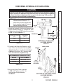
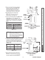
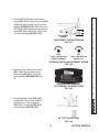
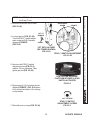
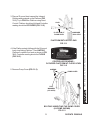
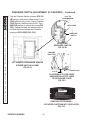
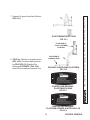
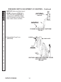
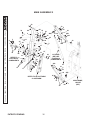
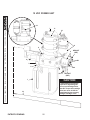
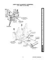
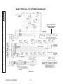
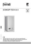
3. Remove cover from top of tower
(FIG. 21-1A).
ADJUSTMENT
SCREW
JAM NUT
LIFT TO
REMOVE
4. Loosen jam nut (FIG. 21-1B)
on the STOW switch adjust COVER
ment screw. Then turn adjustment screw 1/2 turn clockLIFT WITH LH PUMP
wise (FIG. 21-2).
(LH TOWER SHOWN)
FIG. 21-1A
STOW SWITCH ADJUSTMENT
FIG. 21-1B
5. Repeat step 1 to stow the Lift and
check the Platform in the stowed
position.
CW - 1/2 TURN
STOW SWITCH
ADJUSTMENT SCREW
FIG. 21-2
6. When adjustment is complete, tighten
jam nut (FIG. 21-1B) on the STOW
switch adjustment screw.
7. Reinstall cover on tower (FIG. 21-1A).
21
PATENTS PENDING
11921 Slauson Ave. Santa Fe Springs, CA. 90670 (800) 227-4116 FAX (888) 771-7713
NOTE: The STOW switch adjustment screw is always on the same side of the Lift as
the Pump Cover.