1
2002
DMS-100 Family
QUICK
REFERENCE
GUIDE
TAM-1001-018
Standard 09.01
August 2002
YOUR GUIDE FOR:
• Commonly used DMS CI: level commands
• Commands for TABLE EDITOR, SFDEV, DMSSCHED
SPMS, TABAUDIT, DMSMON, TRAVER, DISPCALL,
SHOWAUD, LOGUTIL, DLOG, CLASS, DISKUT,
DSKUT, PRSM, OMs, SOC, AFT, RASL, AUTOMATIC
IMAGE DUMP, and SDM UNIX commands
• Quick references for AIN, CCS7, LNP, ISDN, CLASS,
ACD-MIS, CC MIS, SMDI, CompuCALL, Remotes, DMS250, STP Broadband, SDM, SPM, and Centrex IP
• Tier II support tools for XPMIST, DEBUG, ISDN Q931,
SPM PRI Q931, ACDDEBUG, TERMTRACE, C7TU,
CALLTRAK, XPMTRAK, CMINFO, and REMLOGIN
• Quick references for NTPs, IMs, and other documents
• Product Engineering Codes (PECs) for circuit packs
• Hardware shelf diagrams with circuit pack locations
• Circuit pack descriptions section
• SuperNode, XPM, and other diagrams
• XPM/DTC port and link mapping diagrams
• TOPS hardware including IP-XPM Gateway
• TOPS MPX/IWS & Attendant Console keyboard layouts
• DPP/BMC hardware and DPP commands
• SuperNode, SPM, XA-Core, and other hardware
• RTIF commands and procedures
• DIP switch settings for 6X21, 6X50, and 6X85 DS1 cards
Please read before using
The 2002 DMS-100F Quick Reference Guide provides a quick reference for commonly used commands, utilities, tools, hardware,
and other job-supporting information. The intent of this document
is not to replace Nortel Networks Technical Publications (NTPs)
and other supporting documents. Its purpose is to consolidate as
much usable job-related information as possible into a small
pocket-size document for quick reference and on-the-job use.
The 2002 DMS-100F Quick Reference Guide is intended for both
Tier I and Tier II support users. Tier II support tools are segregated
in an area near the back of the guide. Since the misuse of these
tools could impair service, they should only be used by technicians
that have been trained in their use.
When there is a question about the technical accuracy of this document and its contents, the NTPs and other supporting documents
have the final authority. Where possible, the information in this
guide makes references to NTPs and other supporting documents.
Those documents should be referenced for warnings, cautions,
and other advisory information that may not exist in this guide due
to the limitation of space.
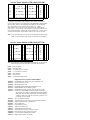
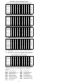
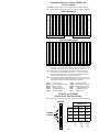
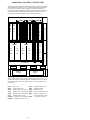
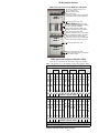
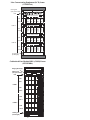
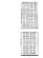
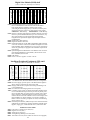
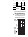
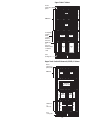
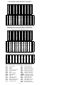
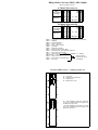
Hardware displayed in this document provides examples for reference to circuit pack slot locations. For most of the examples, the
vintages (releases) of various packs are not shown due to space limitations. Hardware examples may not be exactly as your office is
provisioned due to optional pack assignments and the quantity of
circuits equipped. For a list of packs and their vintage application,
reference the PEC Code list and the circuit pack description area of
this guide. Other supporting information can be found in the DMS100F Baseline Report and NTP 297-8991-805.
Some of the hardware listed within this guide has been manufacture
discontinued (MD’d). It has been left in the guide to support MD’d
hardware that is inservice, and in most cases, still supported.
For customers to order copies of this document within North America, call toll free 1-877-662-5669 (Option 2, then Option 1). Nortel
employees can order copies through Internal Distribution or
through the Documentation Ordering Tracking System (DOTS)
(see IDS Home Page at http://zrtps08m.us.nortel.com/).
Any customer comments, suggestions, or corrections should be
made through your Nortel Networks Regional Support Center.
© 2002
Nortel Networks
Printed in the United States of America.
This document, or parts thereof, may not be reproduced without
the written permission of Nortel Networks.
Nortel Networks Confidential: The information contained in this
document is the property of Nortel Networks. Except as specifically authorized in writing by Nortel Networks, the holder of this document shall keep
the information contained herein confidential and shall protect same in
whole or in part from disclosure and dissemination to third parties and use
same for evaluation, operation, and maintenance purposes only.
Information is subject to change without notice. Nortel Networks reserves
the right to make changes in design or components as progress in engineering and manufacturing may warrant.
Nortel, Nortel Networks, DMS, DMS SuperNode, DMS-STP, and MAP
are examples of trademarks of Nortel Networks. All other trademarks are
the property of their respective holders.
2002
DMS-100 FAMILY
QUICK
REFERENCE
GUIDE
TAM-1001-018
August 2002
© 2002 Nortel Networks
All rights reserved
Printed in the United States of America
This document, or parts thereof, may not be reproduced without
written permission of Nortel Networks.
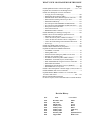
WHAT’S NEW OR CHANGED FOR THIS ISSUE
Page(s)
• Added alphabetical index in back of the guide ............. 161—166
• Updated entire document for and through NA017
• Added more SPM quick reference information:
— Verifying Crossover Messaging ......................................... 108
— SPM Primary Rate Interface (PRI)..................................... 109
— SPM PRI Trunk Tables Datafill Sequence and Notes ........ 109
— SPM Trunk Provisioning Limits for pre-SP16....................110
— SPM EXECTAB lineup.......................................................110
— Exec lineups in table MNNODE for DMS250/500 ............110
— Exec lineups in table MNNODE for DMS100 offices........110
— DAL prefix on the same SPM .............................................111
— LED Alarm Indicators.........................................................112
— PREPDATACHNG command.............................................112
• Added SPM PRI Q931 Message Tracing Tool ....................... 150
• Added Centrex IP Client Manager Quick References:
— PTE2000 Centrex IP Frame.................................................. 45
— Centrex IP Gateway MCG CPX8216T Chassis................... 45
— Centrex IP and Conventional Centrex Configuration .......... 46
— Centrex IP Client Manager Documentation References ...... 46
— Event Logs............................................................................ 46
• Added more SDM UNIX commands ...................................... 127
• Added TOPS IP-XPM Gateway Peripheral ............................ 125
• Updated and added more PRISM information:
— AUTOPROC command........................................................ 25
— Missing PRSU Files ............................................................ 23
— Obsolete/Obsolete Emergency PRSUs at VA status ........... 23
— Patching After Loading (PAL) ............................................ 25
— Post-Release Software Updates (PRSU) Statuses ............... 22
— PRSM Basic Commands, Syntax, and Examples ................ 24
— PRSU EXTENSIONS Using the Format 'AAANNTaa' ...... 22
— SPM loadfile destinations .................................................... 23
— SPM Patching After Return To Service (SPARTS) ............. 25
— Which PRSU files to keep/erase ......................................... 22
• Added Common Peripheral Controller Equip. (CPCE) Frame 115
• Added FINDREF and CAPCI commands................................... 8
• Updated DEBUG BRISC and XA-Core verification data
for NA015 and NA017................................................ 154 — 155
• Removed PATCHER information.
• At Nortel’s request, removed UE9000 and AccessNode Products.
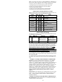
Revision History
Issue
01.01
02.01
03.01
04.01
05.01
06.01
07.01
08.01
09.01
Date
December 1993
May 1995
March 1996
January 1997
January 1998
January 1999
January 2000
February 2001
August 2002
Cover Color
White
Blue
Green
Brown
Black
Light Gray
Red
Spanish Maroon
Dark Green
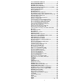
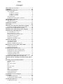
Table of Contents
Abbreviations and Acronyms ................................................................ 1
Nortel Networks Technical Publications .............................................. 2
Installation Documentation .................................................................... 5
Software Optionality Control (SOC) .................................................... 7
DMS CI: Level Commands .................................................................... 8
OM Commands ..................................................................................... 10
Store File Editor Commands ............................................................... 11
Switch Performance Monitoring System (SPMS) Commands ......... 12
DMS Scheduler (DMSSCHED) Commands ....................................... 12
Table Audit (TABAUDIT) Commands ............................................... 12
LOGUTIL Info, Control, Routing, and Devices Commands ............ 13
LOGUTIL Log Browsing Commands ................................................ 13
DMSMON Commands ......................................................................... 14
DISPCALL Commands ........................................................................ 14
SHOWAUD Command ........................................................................ 14
IOC DSKUT NonMenu Commands ................................................... 15
SLM DISKUT NonMenu Commands ................................................. 15
Supernode Loading Procedure ............................................................ 15
RTIF Commands and Recovery .......................................................... 16
AMADUMP Commands ...................................................................... 17
CALLDUMP CI: Level Command ..................................................... 17
Mag Tape (9 Track) Commands ......................................................... 17
AFT and RASL Commands ................................................................. 17
TRAVER Commands ........................................................................... 18
CLASS Quick References .................................................................... 19
Table Editor Commands ...................................................................... 21
Pending Order Subsystem .................................................................... 21
DLOG Commands ................................................................................ 22
Post-Release Software Manager (PRSM) Quick References ............ 22
Automatic Image Dump ....................................................................... 26
Calculating Node and Terminal Numbers .......................................... 27
Ringing Quick References .................................................................... 28
Trunk Group Types Quick References ............................................... 29
ISDN Quick References ........................................................................ 30
AIN Quick References .......................................................................... 33
Local Number Portability (LNP) Quick References .......................... 34
ACD-MIS Quick References ................................................................ 35
DMS-250 Quick References ................................................................. 38
CC MIS Quick References ................................................................... 40
CompuCALL Quick References .......................................................... 42
SMDI Quick References ....................................................................... 43
Centrex IP Client Manager Quick References ................................... 45
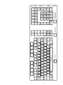
Attendant Console Quick References ................................................. 47
Attendant Console Lamp Keyboard Layout ...................................... 48
Attendant Console Lamp to Physical Key Mapping ......................... 48
Attendant Console Internal to Physical Key Mapping ...................... 48
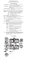
CCS7 Quick References ....................................................................... 51
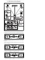
CCS7 Fault scenario concerns a single link failure ............................ 53
CCS7 Fault scenario concerns a linkset with two “A” links. ............ 54
CCS7 Fault scenario concerns both links failing ............................... 55
CCS7 Fault scenario concerns a single STP failure. .......................... 56
Broadband STP Quick References ...................................................... 57
PEC CODES & Description ................................................................. 59
Circuit Pack Descriptions .................................................................... 72
Office Hardware Inventory Package (OHIP) Table .......................... 86
Ringing Generators ............................................................................... 86
XPM Link Configuration ..................................................................... 88
DIP Switch Settings for 6X50 and 6X85 DS1 Cards .......................... 90
DIP Switch Settings for 6X21AD Line Card ...................................... 91
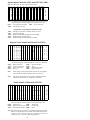
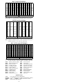
Junctored Double Shelf Network (MD) .............................................. 92
Input/Output Controller (IOC) shelf (MD) ........................................ 93
Digital Carrier Module (DCM) shelf .................................................. 93
Trunk Module (TM8) shelf ................................................................. 93
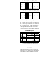
Line Module (LM) shelf (MD) ............................................................. 94
Remote Line Module (RLM) shelf (MD) ............................................ 94
LM/RLM Ringing Table ...................................................................... 94
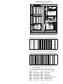
Maintenance Trunk Module (MTM) shelf ......................................... 95
Remote Maintenance Module (RMM) shelf ...................................... 95
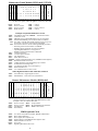
Integrated Services Module (ISM) shelf .............................................. 96
Input Output Module (IOM) (Located in ISM shelf) ........................ 96
ISM test trunk assignments to MLT and other test equipment ....... 97
Remote Interface & Maintenance (RIM) shelf .................................. 97
GPP CPM Main and Extension shelves .............................................. 98
i
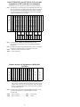
Service Trunk Module (STM) shelf ................................................... 99
Service Trunk Module (STM) shelf ................................................... 99
DRAM (modified MTM) shelf .......................................................... 100
DRAMREC Utility Commands ......................................................... 100
Subscriber Carrier Module Shelves .................................................. 101
Expanded Subscriber Carrier Module-100 Access 2 (SMA2) ........ 102
Small Remote Unit (SRU) (MD) ........................................................ 103
Star Remote Hub Control shelf ......................................................... 104
Remotes Quick Reference .................................................................. 105
SPM Quick References ....................................................................... 106
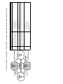
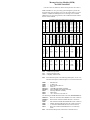
Digital Trunk Controller (DTC) shelf ............................................... 113
Line Trunk/Line Group Controller (LTC/LGC) shelf ................... 113
ISDN LTCI/LGCI/DTCI Common Peripheral Controller shelf ... 113
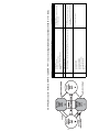
International PLGC or PLTC shelf ................................................. 114
International PDTC shelf .................................................................. 114
Intelligent Cellular Peripheral (ICP) shelf ....................................... 114
ICP Overseas (ICPO) shelf ................................................................ 114
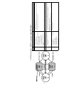
Common Peripheral Controller Equipment Frame....... ................. 115
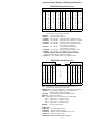
Line Concentrating Array (LCA) LCM Unit 0 shelf ...................... 116
Line Concentrating Array ISDN (LCAI) LCME ............................. 116
Line Concentrating Equipment (LCE) frame................................... 117
Cabinetized Line Module ISDN (CLMI) Frame .............................. 117
Digital Line Module (DLM) shelf ...................................................... 119
Intelligent Peripheral Equipment (IPE) shelf .................................. 119
Remote Cluster Controller (RCC) shelf ............................................ 120
Cabinetized Remote Switching Center/ISDN (CRSC/ISDN) ........ 120
RCC2 shelf .......................................................................................... 121
RCC2 Port Provisioning ..................................................................... 121
RCC2–EXT shelf ............................................................................... 121
Outside Plant Access Cabinet ............................................................ 122
Outside Plant Module ......................................................................... 123
OPM-256 Bay Frame Configuration ................................................ 123
Message Services Module (MSM) for DMS VoiceMail ................... 124
TOPS Message Switch (TMS) shelf.................................................... 125
TOPS IP-XPM Gateway Peripheral ................................................. 125
TOPS MP Configuration with TMS ................................................. 125
SuperNode Data Manager (SDM) Quick References ...................... 126
SuperNode Cabinet ............................................................................. 128
SuperNode Switch Enhanced (SNSE) Cabinet ................................ 128
Message Switch (MS) shelf ................................................................ 129
Computing Module (CM) Processor shelf ........................................ 129
System Load Module (SLM) shelf .................................................... 130
Enhanced Network (ENET) shelf ...................................................... 130
Link Peripheral Processor (LPP) ...................................................... 131
File Processor shelf (NT9X81AA) (MD) ........................................... 134
File Processor Storage Device shelf (MD) ........................................ 134
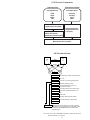
SuperNode SNSE Block Diagram ..................................................... 135
SuperNode SE Message Switch shelf ................................................ 136
SuperNode SE CM/SLM shelf ........................................................... 136
SuperNode SE 16K ENET shelf ........................................................ 137
SuperNode SE LPP Link Interface shelf .......................................... 137
XA-Core shelf (NTLX0101) ............................................................... 138
Distributed Processing Peripheral (DPP) ......................................... 139
Billing Media Converter (BMC) (MD’d 4Q00) ................................ 144
XPMTRAK .......................................................................................... 146
ACDDEBUG ....................................................................................... 146
XPMIST ............................................................................................... 147
TERMTRACE Setup .......................................................................... 147
REMLOGIN Command ..................................................................... 147
XPMIST Call Processing Messages .................................................. 148
XPMIST Breakdown for Attendant Console ................................... 149
Decimal to HEX to Binary Chart ...................................................... 149
ISDN BRI Troubleshooting PM180 and PM189 Logs .................... 150
SPM PRI Q931 Message Tracing Tool (MSGTRAC) ..................... 150
ISDN Q931 Procedures for Traces on BRI and PRI ....................... 151
XPMIST Breakdown for EBS ........................................................... 153
Debug Verification of Line State ....................................................... 154
Debug Verification of Trunk State .................................................... 154
CMINFO Special System Query Commands ................................... 155
CALLTRAK ........................................................................................ 156
CCS7 Test Utility (C7TU) .................................................................. 157
NOTES ................................................................................................. 159
ASCI to HEX ....................................................................................... 159
NOTES ................................................................................................. 160
INDEX ...................................................................................... 161 — 166
ii
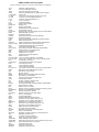
Abbreviations and Acronyms
(NTP 297-1001-825, Glossary of Terms & Abbreviations Ref Manual)
ACD
AIN
AMA
ASCII
CALLTRAK
CC MIS
CLASS
CCS7
C7TU
CM
DCM
DISPCALL
DLM
DPP
DSNE
DTC/DTCI
DMS
DISKUT
DRAM
DSKUT
DTM
EBS
EDRAM
ENET & JNET
GPP
CPM
IOC & IOM
ISDN
ISM
ISN
IPE
ISUP
LCM & LCMI
LGC & LGCI
LIU7
LM & RLM
LMS
LNP
LRN
LTC & LTCI
MAP
MD
MS
MSM
MTM
NTP
OPM
PCL
PEC
PRSM
QRG
RCC
RCC2
RLM/RLCM
RMM
RSC/RSCI
SCP
SLM
SMDI
SMA
SMR
SMR-RCT
SMS
SMU
SNSE
SPM
SP/SSP
STM
STP/SSP
STP
TAM
TOPS
TOPS IWS
TOPS MPX
TOPS-TPC
TMS
TRAVER
XPMIST
Automatic Call Distribution
Advanced Intelligent Network
Automatic Messaging Accounting
American Standard Code for Information Exchange
Call Tracing
Call Center - Management Information System
Custom Local Area Signaling Services
Common Channel Signalling No. 7
CCS7 Test Utility
Computing Module
Digital Carrier Module
Display Call
Digital Line Module
Distributed Processing Peripheral
Double Shelf Network
Digital Trunk Controller/Digital Trunk Controller ISDN
Digital Multiplex System
Disk Utility (SLMs)
Digital Recorded Announcement Machine
Disk Utility (DDUs)
Digital Trunk Module (EDRAM peripheral module)
Electronic Business Set
Enhanced Digital Recorded Announcement Machine
Enhanced Network and Junctored Network
Global Peripheral Platform (International)
Common Peripheral Module
Input Output Controller and Input Output Module
Integrated Services Digital Network
Integrated Services Module
Intelligent Service Node
Intelligent Peripheral Equipment
ISDN User Part
Line Concentrating Module / LCM ISDN
Line Group Controller / Line Group Controller ISDN
Link Interface Unit (SS7)
Line Module and Remote Line Module
Local Message Switch
Local Number Portability
Location Routing Number
Line Trunk Controller and Line Trunk Controller ISDN
Maintenance and Administration Position
Manufacture Discontinued
Message Switch
Message Services Module (DMS Voicemail)
Maintenance Trunk Module
Nortel Networks Technical Publication
Outside Plant Module
Product Computing-module Load
Product Engineering Code
Post Release Software Manager (Replaced PATCHER)
Quick Reference Guide
Remote Cluster Controller
Remote Cluster Controller 2 (Remote Switching Center)
Remote Line Module/Remote LCM
Remote Maintenance Module
Remote Switching Center/RSC ISDN
Service Control Point
System Load Module
Simplified Message Desk Interface
Subscriber Carrier Module-100A Access
Subscriber Carrier Module-100R Remote
SMR-Remote Concentrating Terminal
Subscriber Carrier Module-100S (SLC-96)
Subscriber Carrier Module-100 Urban
DMS SuperNode Small Exchange
Spectrum Peripheral Module
Signalling Point/Service Switching Point
Service Trunk Module
Signalling Transfer Point/Service Switching Point
Signalling Transfer Point
Technical Assistance Manual
Traffic Operator Position System
TOPS Intelligent Work Station
TOPS MPX (Provides Dir. Assist. and Intercept Services)
TOPS-Terminal Position Controller
TOPS Message Switch
Translation Verification
XPM Intercept System Test
1
Nortel Networks Technical Publications
(NTP 297-8991-001, DMS-100 Product Documentation Directory)
Note: See NTP 297-8991-001 for a list of Nortel Networks Technical
Publications (NTPs). Also, see NTP 297-8991-002, Cancellation
Cross Reference Directory for a cross-reference list of canceled and
replacement documents.
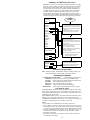
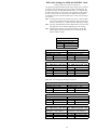
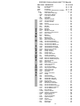
DMS-100F Documentation Numbering
DMS-100F NTPs are identified by a ten-digit number (XXX-YYYY-ZZZ)
that is divided into three blocks. The document division number, XXX,
denotes the system. For the purpose of this QRG, only the 297 division
number is used:
• 297 = Digital Multiplex System (DMS)
The document layer number, YYYY, denotes the Product Computing-module Load (PCL) or product name. Within the documentation structure, the
document layer number is dependent upon the PCL number for the specific
software load. Following is a list of DMS-100F layer numbers and their
products even though some are manufacture discontinued (MD):
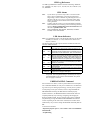
PCL Layer #
PCL Name or Product Name
0201
NA Service Priority Classifications Descriptions
1001
DMS-100 Family
1003
NAV Family Audiogram Delivery System
1011
DNC-50, DNC-100, DNC-500 Dynamic Net Cont Systems
1021
Network Operations Systems Station Detail Server DNC-50
1091
NAV Family Applications Vehicle
1301
DMS-100F TOPS Voice Service Node
1421
DMS-100F Subscriber Services
1771
DMS Spectrum Peripheral Module (DMS-SPM)
2011
Meridian Business Sets
2013
NAV Family PowerView Services
2031
DMS-100 Family Attendant Console
2041
DMS-100 Family Automatic Call Distribution (ACD)
2061
DMS-100 Family Customer Data Change
2071
DMS-100 Family MDC Station Message Detail Recording
2081
DMS-100 Family MDC ACD-MAX 3.5
2101
DMS-100 Family Remote Line Module (RLM)
2121
DMS-100 Family Line Engineering Guidelines (DataPath)
2211
DMS-100F Automated Directory Assist. Service (ADAS)
2251
DMS-100 Family TOPS Intelligent Work Station (IWS)
2271
DMS-200 TOPS 04 (Canceled)
2281
DMS-100 Family TOPS MP
2291
DMS-100 Family TOPS MPX
2401
DMS-100F Integrated Services Digital Network (ISDN)
2451
DMS-100 Family Digital Network Termination Eng/Guides
2461
DMS-100F DMS SuperNode Dialable Wideband Services
2667
DMS-100F SDM Carrier User Guide
2671
DMS Call Center Management Information Sys (CCMIS)
5001
DMS-100F DMS SuperNode & DMS SuperNode SE
5051
DMS-100F SuperNode Data Manager (SDM)
5061
DMS-100 Family SDM Troubleshooting and User Guides
5111
DMS-100F DMS SuperNode DataSPAN Frame Relay Serv
5151
DMS-100 Family E800 SSP toll-free numbers
5161
DMS-100 Family Advanced Intelligent Network Essentials
6201
DMS-10/DMS-100 Billing Media Converter II
7001
DMS-10/DMS-100 DMS VoiceMail
8001
U.S. Stand-alone DMS-100/200
8021
U.S. DMS-100/200 TOPS Combination
8063
DMS-100 Family 1 Meg Modem Services Network
8081
DMS-200 Translations
8091
DMS-100 Wireless
8101
Signaling Transfer Point (STP) Base
8111
Signaling Transfer Point MDR7
8121
STP Signaling Engineering & Administration Sys. (SEAS)
8211
Outside Plant Access Cabinet (OPAC)
8221
Remote Switching Center (RSC)
8223
DMS-100F Remote Switching Center Multi-Access
8231
Subscriber Carrier Module-100S (SCM-100S)
8241
Subscriber Carrier Module-100 Urban (SCM-100U)
8251
Subscriber Carrier Module-100 Access (SCM-100A)
8253
Subscriber Carrier Mod-100 Access (MVI-20) (SCM-100A
8261
RSC-SONET Model A (DS1)
8263
SCM-100A Maintenance Manual (SCM-100A)
8271
RSC-SONET Model A (PCM30)
8281
RSC-SONET Model B (DS1)
8291
RSC-SONET Model B (PCM30)
Continues on the next page.
2
8301
8321
8331
8341
8351
8361
8353
8403
8411
8421
8441
8501
8531
8601
8981
8991
Subscriber Carrier Module-100S Remote (SCM-100SR)
Extended Peripheral Module (XPM) (DS1)
Extended Peripheral Module (XPM) (PCM30)
TOPS Message Switch
RLCM Manual
Outside Plant Module (OPM)
Star Remote System
Operator Services System AIN (OSSAIN)
TOPS (Stand-alone US) (USTOPS)
TOPS (Stand-alone Canadian) (CDNTOPS)
DMS-100F Global TOPS Solo
DMS SuperNode Service Control Point (SCP) II
Network Switching Systems Advanced Intelligent Network
DMSGL002
DMS Global
North American common
PCL common, miscellaneous, & documentation directories
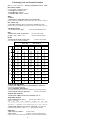
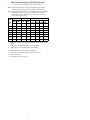
Key Numbers
The last three digits of the NTP, ZZZ, denotes the type of NTP and is called
the key number. The following table lists NTP types and their associated
key number. It includes all currently used PCL and XPM key numbers.
NTP Type
Key Number
Translations Guide........................................................................ 350
Alarm and Performance Monitoring Procedures ......................... 543
Trouble Locating and Clearing Procedures ................................. 544
Recovery Procedures .................................................................. 545
Routine Maintenance Procedures ............................................. 546
Card Replacement Procedures..................................................... 547
XPM Maintenance Manual (remotes only, layers 8201 - 8353).. 550
Peripheral Module Software Release .......................................... 599
Feature Description Manual......................................................... 801
Hardware Description Man. (layer 8991 only) ........................... 805
Service Order Reference Manual ............................................. 808
XPM Operational Measurements Reference Manual
(remotes only, layers 8201 - 8331).............................................. 814
XPM Translations Reference Manual ......................................... 815
Log Reports Reference Manual
............................................. 840
Office Parameters Reference Manual ......................................... 855
Software to Data Cross-Reference ............................................. 856
NTP 297-1001-ZZZ DMS-100 Family Documents
Electrostatic Discharge Protection....................................... 297-1001-010
DPP Product Guide.......................................................................1001-019
Maintenance System Maintenance Guide ....................................1001-106
Maintenance and Administration Tools........................................1001-107
Cabinetized Misc Equip Cabinet Planning & Eng Guide ............1001-109
Magnetic Tape Reference Manual ................................................1001-118
AMA NT Format ..........................................................................1001-119
Automatic Trunk Testing (ATT) Description ...............................1001-121
Alarm System Description............................................................1001-122
Journal File Description................................................................1001-127
Input/Output System Reference Manual ......................................1001-129
Synchronous Clock System ..........................................................1001-130
Ringing System Description .........................................................1001-131
Blue Box Fraud Detection Feature Description ...........................1001-132
Trunk Selection and Compatibility...............................................1001-152
Peripheral and Trunk Group/Line Group Assignments................1001-155
Power Distribution and Grounding Guide....................................1001-156
Grounding Audit Procedures ........................................................1001-158
Disconnect on the DMS-100 ........................................................1001-190
DMS-100F Basic Administration Procedures ..............................1001-300
SuperNode Conversion Procedures ..............................................1001-302
ONP - HYBRID Software Application Procedures .....................1001-303
Capacity Administration Guide ....................................................1001-304
Memory Administration Manual ..................................................1001-305
Loading Administration Manual ..................................................1001-306
Service Problem Analysis Administration Guide.........................1001-318
SPMS Application Guide .............................................................1001-330
DPP Administration Guide ...........................................................1001-331
Device Independent Recording Peripheral (DIRP) Guide ...........1001-345
Power - Grounding Routine Maintenance Manual.......................1001-350
Basic Translations Tools Guide ....................................................1001-360
Network Management System Reference Manual .......................1001-453
Maintenance System Human-Machine Interface .........................1001-520
Automatic Board-To-Board Testing Reference Manual...............1001-522
Remote Data Polling System........................................................1001-524
Data Packet Controller Reference Manual ...................................1001-525
NTPs continue on the next page.
3
Disk Maintenance Subsystem Reference Manual ........................ 1001-526
DRAM Maintenance Reference Manual ...................................... 1001-527
Conference Reference Guide........................................................ 1001-530
CCS7 Maintenance Reference Manual ........................................ 1001-531
Bit Error Rate Performance Testing ............................................. 1001-533
Maintenance Managers Morning Report...................................... 1001-535
DPP Hardware Component Replacement Guide ......................... 1001-539
DPP Quick Reference Guide ........................................................ 1001-544
DPP Commands and Messages Guide ......................................... 1001-545
NORESTARTSWACT / MTCSWACT User Guide..................... 1001-546
DPP Maintenance Procedures Guide ........................................... 1001-547
Bellcore Format AMA Maintenance Guide ................................. 1001-570
Input/Output Maintenance Guide ................................................. 1001-590
Networks Maintenance Guide ..................................................... 1001-591
Peripheral Module Maintenance Guide ....................................... 1001-592
External Devices Maintenance Guide .......................................... 1001-593
Lines Maintenance Guide............................................................. 1001-594
Trunks Maintenance Guide ......................................................... 1001-595
Feature Description Manual ......................................................... 1001-801
Non-Menu Commands Historical Ref. Manuals V1 - V4 ........... 1001-820
Menu Commands Historical Reference Manuals V1 - VA.......... 1001-821
Commands Reference Manual ..................................................... 1001-822
Glossary of Terms and Abbreviations Reference Manual ........... 1001-825
Bellcore Format AMA Reference Guide ..................................... 1001-830
Log Report Reference Manual ..................................................... 1001-840
Other NTP & PLN PCL Common & Misc. Documents
LRN - LNP Service Implementation Guide.......................... 297-8981-021
One Night Process (ONP) Service Implementation Guide ... .......8981-022
NT Access User Guide .......................................................... .......8981-301
NA DMS-100 PM Software Release Document................... .......8981-599
DMS-10 – DMS-100 Product Documentation Directory ..... .......8991-001
DMS-10 – DMS-100 Cancellation Cross-Reference Dir..............8991-002
LIU7 External Routing Activation Guide .....................................8991-030
DMS SN STP/SSP IN Functionality Desc Ref Manual................8991-100
Product Computing Module (PCL) Generic Traffic Tables..........8991-101
Cost of Ownership Reduction Feature Specification ....................8991-110
One Night Process (ONP) Software Delivery Procedures............8991-303
ONP SNSE to SuperNode/ENET Conversion ..............................8991-304
Software Delivery XA-Core Maintenance Manual.......................8991-307
DMS-100F Maintenance & Operations Manual ...........................8991-500
XA-Core Maintenance Manual .....................................................8991-510
XA-Core Maintenance Guide........................................................8991-511
Post-Release Software Manager (PRSM) Reference Guide. ........8991-540
DMS-100 Family PRSM Basic Reference Guide .........................8991-541
DMS-100 Family PRSM Quick Reference Guide. .......................8991-542
Common Channel signaling 7 (CCS7) Maintenance Manual.......8991-545
DMS SN STP/SSP Integrated Node Conversion Guide NMA7...8991-580
DMS SN STP/SSP Integrated Node Conversion Guide ..............8991-582
EDRAM PM Software Release Document Voice Files ................8991-597
Enhanced DRAM (EDRAM) PM Software Release Document...8991-598
EDRAM PM Software Release Document & Voice Files ............8991-599
Hardware Reference Manuals V1 through V5..............................8991-805
XA-Core Reference Manual..........................................................8991-810
Command Interface Reference Manual (Aug 1999) .....................8991-824
Software Optionality Control User Manual ..................................8991-901
Software Navigation System User Guide......................................8991-902
High Speed Link Cutover Guide ...................................................8991-906
Ethernet Interface Unit User Guide...............................................8991-910
US GETS HPC Feature Guide ......................................................9501-001
USNBD Feature Guide..................................................................9801-300
DMS-100 Feature Description Manual ................................PLN-1001-003
TOPS MPX Technical Specification ....................................PLN-2291-001
DMS SuperNode Technical Specification............................PLN-5001-001
SDM0010 PCL Rel Doc.......................................................PLN-5051-004
Provisioning Manuals ...........................................................PLN-8991-104
Technical Assistance Manuals (TAMs)
Listing of TAMs ................................................................ TAM-1001-000
TAS Non-Residential Enhanced Services Tool Listing .... TAM-1001-001
DISPCALL User Guide..................................................... TAM-1001-003
PMDEBUG User Guide .................................................... TAM-1001-004
PMIST User Guide ............................................................ TAM-1001-007
DEBUG User Guide .......................................................... TAM-1001-008
Data Layout Manual Reference Manual ........................... TAM-1001-011
CALLTRAK User Guide................................................... TAM-1001-012
MPCDEBUG Central Control Data Analyzer User GuideTAM-1001-013
SCANLOG User Guide ..................................................... TAM-1001-014
C7TU User Guide.............................................................. TAM-1001-014
Super Nonresident Tool Listing......................................... TAM-1001-016
Automatic Message Accounting (AMA) User Guide ....... TAM-1001-017
DMS-100F Quick Reference Guide ................................. TAM-1001-018
DMS-100F Debug System Field Service User Manual .... TIG-3401-004
4
Installation Documentation
Note: The following table of contents for installation methods references
all the methods modules. However, due to space, only the methods
for “Module 24 Equipment Loading and Diagnostics” and “Module
28 Routine System Level Testing” are provided.
MODULE 01 PREFACE MODULE
MODULE 02 PLANNING MODULE
MODULE 03 DMS PHYSICAL HANDBOOK
MODULE 04 GENERAL INFORMATION
MODULE 06 FLOOR PREPARATION
MODULE 08 EQUIPMENT HANDLING AND SECURING
MODULE 10 HARDWARE FABRICATION
MODULE 12 PRIMARY ASSEMBLY
MODULE 14 AC OPERATIONS
MODULE 16 POWER AND GROUNDING CABLING
MODULE 18 SYSTEM CABLING
MODULE 20 SUPPLEMENTAL ASSEMBLY
MODULE 22 PREPARATION AND POWER UP
MODULE 23 ENET UPGRADE
MODULE 24 EQUIPMENT LOADING AND DIAGNOSTICS:
Title
Meth #
0180
OPM Power Verification
0185
Communication Module Installation & Functional Test
0188
Star Remote Mod Outdoor/Indoor Cabinet (NTTR40/45)
0192
SDM Installation/Commissioning for SDI
0207
CPU Micro-code Tests and System Loading
0214
Memory Commissioning Firmware Test
0235
JNET Integrity Test
0238
NNE Software Configuration
0239
BWA - NIU Software Configuration 1.2
0284
BWA Reunion Acceptance Test Plan
0306
Gateway Card (NT7X07) Installation and Configuration
0310
CORE MAINTENANCE TEST
0317
Star Remote Module Commissioning Manual
0345
Host Peripheral Module Diagnostic Tests
0350
Trunk Diagnostics Tests (Carrier/TTP)
0395
IW-SPM/IW-SPM IP Commissioning Guide
0396
GBMD13 Installation
0397
GEM13 Call Intercept Provisioning Center
0398
Simplex SS7/IP Gateway Install & Commissioning Method
0399
SS7/IP Gateway Installation & Commissioning Method
0419
NGS WPP Release 04 Base Software Installation
0469
MicroNode Switch
0753
Audio Provisioning Server Verification & Configuration
0770
Base Commissioning for Passport 6K, 7K, and 8K
0831
DDU Installation Testing and Retrofit Procedure
0854
Installation and Commissioning of NTLX04AA HIOP Card
0875
Commissioning of 9 Track Magnetic Tape Drives
1443
Star Remote Hub Equipment (SRHE) Frame
1497
SRHE Commissioning for DMS-100
1865
Commissioning of EMPC Card for Turbolink
1901
Installing and Commissioning of NT1X89 Card for SMDI
1903
Comm. of EMPC CP for Rem Poll’n & Patch Downloading
4186
System Diagnostics Certification
5004
Log Monitoring
5043
LIS Loading and Diagnostic Tests for SSLPP and SNSE
5059
Digital Line Module (DLM) Testing
5138
SuperNode Data Manager (SDM-FT) Instal/Commissioning
5158
LPP/LIM Loading and Diagnostic Tests
5159
ASU Commissioning on the LPP/SSLPP and the
5176
ISDN Line Card Diagnostic Tests
5180
Addition and Testing of Stratum 2 Clock - DMS SuperNode
5200
PRI Commissioning Process
5218
Application of Patches to XPMs
5222
PMTESTER Users Guide
5225
Core Tester
5228
SuperNode Data Manager (SDM-FT) for SDMX0011 NCL
5229
SDM-SX Installation/Commissioning
5230
ISDN Integrated Line Testing
5235
Automated Span Test
5236
SDM-FT Installation for SDMX0012 to SDMX0014
5257
Miscellaneous Hardware Tests
5281
Shell-TG and DFIL Users Guide
5340
Line Continuity Testset (LCT) Procedure
5515
EDSPM Loading and Commissioning
5550
Remote Switching Center - Multi Access Testing
Continues on the next page.
5
5638
5682
5771
5776
5777
5778
5812
5941
6114
6120
6123
6129
6132
6133
6547
6577
6750
7920
7960
9530
9701
9702
Commissioning of the Input Output Module (IOM)
Meridian Service Module (MSM) Stand-Alone/CPE
Centrex and Operational Installation
Application Processor Cab. (APC) Loading & Diag. Tests
TOPS VSN Load and Boot System
TOPS VSN System Access
TOPS VSN - Display or Test Status of SRU, PRU, or RRU
Network Appl. Vehicle (NAV) Commissioning Procedures
SS7/IP Gateway 2.0 Installation and Commissioning
PC/Office RTIF for XA-Core
SLM Data Transfer for SuperNode SE Upgrades
XA-Core Cutover Software Loading
MS Boot Testing for SN CM/SLM to XA-Core Upgrades
SLM Data Transfer for SN CM/SLM to XA-Core Upgrades
MS Boot Testing for SNSE CM/SLM to XA-Core Upgrades
TOPS Message Switch (TMS) Digital Trk Card Diagnostics
Remote Peripheral Module Diagnostic Tests
SPM Physical Installation and Commissioning
Alarm Verification Test - RLCM
Alarm Verification Test - OPM or OPM256
IOC to IOM Datafill
XPM Commissioning Guide
LCE/LCEI Commissioning Guide (Automated Test Only)
MODULE 26
MODULE 28
Method #
0208
0232
0355
0366
0380
0405
0410
0426
0443
0446
0449
0451
0454
0457
0461
0472
0475
0482
0483
0487
0829
904.2
1437
1575
1587
2123
5005
5064
5065
5066
5135
5163
5168
5250
5472
5501
5503
5575
5576
5623
5645
5690
5765
5767
5768
5772
5779
5780
5781
5811
OEM VENDOR MODULE
ROUTINE SYSTEM LEVEL TESTING:
Title
Remote Maintenance Control Feature Tests
OPAC Power and Environmental System (PES) Tests
Digital Recorded Announcement Machine (DRAM) Tests
Alarm Testing
Emergency Action Procedure
TGA Users Guide
Test Line Operational Tests
Scan and Signal Distribution Point Test
RLCM/OPM/OPAC Operational Tests
Installation Operational Measurement Setup
SCM-100R Interface Tests
Outside Plant Module (OPM) Power & Enviro. Tests
SMS Interface Tests
SMU/ESMU Interface Tests
Tones and Announcements
ROTL (Remote Office Test Line) Tests
Fault Location Tests
Remote Assessment Test
Assessment Tests for DMS-100 Family Offices
Mini-Frame User Guide
Stratum II Synclock Feature
RLCM/OPM ESA
S/DMS Billing Server Application Commissioning
Providing Service for ISDN Terminals
EDRAM & CTM Installation & Testing for Meridian Cab.
TOPS Tone & Scrambler Circuit
RSC/RSC-Sonet Operational Tests
DataSpan Frame Relay Traf. Generated Operational Testing
ENET - System Integrity Test (E-SIT)
SOS Traffic Generator Users Manual
Conference Trunk Module (CTM) Installation and Testing
#7 Message Generator Traffic Simulator (MGTS)
Signaling Transfer Point Assessment Test
CompuCALL System Test
Alarm Testing for NTNXxxxx Style Cabinets
ISDN BRI Operational Tests
Installation and Upgrade of the NT1X89 (E)MPC Card
TOPS MPX NT DA AOSS Stand-Alone Tests
TOPS IWS Stand Alone Tests
Synchronization Feature Tests - DMS-SuperNode
CCS7 Loopback Tests
TOPS MPX Audio Board Level Tests
TOPS MPX Stand-Alone Tests
TOPS MPX Transmission Tests
TOPS MPX Operational Test
TOPS MPX Toll and Assist Stand Alone Tests
TOPS VSN - Remove/Restore Service for SRU/PRU/RRU
TOPS VSN - Operational Tests
TOPS VSN Spare Circuit Pack Testing
Message Delivery System (MDS) Commissioning
Continues on the next page.
6
6149
6553
6556
6558
6562
6564
6565
6566
6567
6568
6569
6570
6571
6572
6573
6574
Spares Testing for the XA-Core
Ameritec AM1 ISDN Bulk Call Generator
SCM Remote Transfer Guide
Subscriber Module SLC-96 Remote (SMSR) NT6X02PD
Ameritec AM1 SPA/SPD Bulk Call Generators
TOPS MP Stand Alone Tests
TPC Administration
TOPS MP Computer Assisted Training
TOPS Multipurpose Pos. (TOPS MP) Transmission Tests
Digital Multiplex System TOPS MP Operational Tests
TOPS MP Equal Access Feature Tests
TOPS MP AMA Tape Tests
TOPS MP Automatic Coin Toll Service (ACTS) Tests
TOPS MP Sw. Sys. for Miscellaneous Call Type & Features
Test for Misc. TOPS MP Terminals & Alarm Conditions
DMS TOPS MP Assessment
MODULE 30
MODULE 35
MODULE 47
MODULE 53
MODULE 65
MODULE 68
MODULE 70
TURNOVER
SYS. GROWTH
DY-DOCS
REMOVALS
UPGRADES
RETROFITS
REGRADE
MODULE 72
MODULE 74
MODULE 76
MODULE 78
MODULE 80
REHOMES
CONV. APPL.
HOTSLIDES
CUTOVERS
GEN. SERVICES
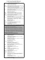
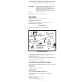
Software Optionality Control (SOC)
(297-8991-901, DMS-100F Software Optionality Control User Manual)
Software optionality control (SOC), part of the DMS Evolution product
delivery process, facilitates the definition and delivery of product computing module loads (PCL). Once the new PCL is loaded, all the features it
contains can be activated by the customer as needed without a software
reload. The user interface for SOC consists of SOC level commands on the
MAP terminal. The ASSIGN, SELECT, DBAUDIT and REMOVE commands on the SOC level allow you to:
• assign right-to-use (RTU) to an option.
• remove RTU from an option.
• assign a usage limit to an option.
• assign RTU or usage limits to a group of options using a key code file.
• assign the on or idle state to an option.
• assign a warning threshold to a usage option.
• generate a report about one or more options in a PCL.
• perform an audit of the SOC database.
SELECT command
This command displays information about options. There are several types.
>SELECT <select_type> <value> [<report_type>]
>SELECT ALL [<report_type>]
DBAUDIT Command
This command performs a detailed audit and reports any internal database
inconsistencies as well as any discrepancy between a database value and a
feature’s reported value.
ASSIGN RTU & REMOVE RTU commands
When an operating company purchases a state option, Nortel gives the
operating company a password called a key code for the option. Once the
key code is known, the ASSIGN RTU command can be used to grant the
operating company permission to change the state of the option. The
REMOVE RTU command allows operating company personnel to remove
the right-to-use (RTU) from a state option.
7
DMS CI: Level Commands
(NTP 297-1001-820, 821, or 822, Command Reference Manual)
(NTP 297-1001-129, Input/Output System Reference Manual)
Note: Use >HELP <command> to get more details of the following
CI: level commands, except for some like the ABORT command.
>ABORT
use if difficulty is experienced with using a command.
>CALLDUMP outputs billing records using same format as AMADUMP
>CLLIREF use parameter MEMBERLESS to search for CLLIs in table
TRKGRP against table TRKMEM CLLIs. Use SEARCH
parameter to search for CLLI(s) in all or specified tables.
>CLLIRBT use to scan for differences between table CLLI and
CLLIMTCE or between TRKMEM and CLLIMTCE subtable DIAGDATA. Generates DFIL106 log if problems.
>COMMAND <x> (full command name)
used to create user defined commands to simplify
routine or repetitive input tasks.
(i.e., COMMAND T (TABLE)). T is now TABLE
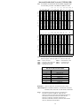
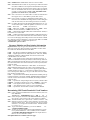
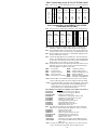
>CPSTAT
display of SuperNode switch activity.
Example of CPSTAT results for a SuperNode:
CATMP/HR CPOCC AUXCP CPAVAIL ENGLEVEL ENGPARM CCOVRLD
840
2%
0%
79%
BELOW
77%
OFF
SCHED FORE MAINT DNC OM GTERM BKG NETM SNIP IDLE
13%
1%
6%
0%
1%
0% 33%
0%
0% 46%
>CAPCI
display of XA-Core switch activity.
Example of CAPCI results for a XA-Core:
CATMP/HR UTIL ENGCATMP MAXCATMP COMPLEX ENGLEVEL CCOVRLD PESC
0
0%
---BELOW
OFF
NO
Do Not Disturb (DND) Queries:
>DND STATUS
displays next wakeup time (table DNDSCHED).
>DND DISPLAY <custname> <disprange> {DN7D <dn>, GRPNO
[<group> {1 to 63}], ALLGRPS, INTERVAL}
displays individual DN or group data.
>DTDETECT
command to activate digitone fraud program.
Suggest using this program after a restart to prevent
no-dial-tone customer reports from customers that are
not supposed to have digitone phones.
>EXPAND
use to uncompress files.
>ERASE
deletes a symbol from the user's directory
(i.e., ERASE T to erase command named “T”).
>FILECLOSE <filename> <device> closes a specified store file/device.
>FINDTAB Finds all tables which begin with a specific set of letters.
The output indicates the table's position in the DART table,
the dump and restore method and the complete table name.
(i.e. >FINDTAB OFC will find all tables beginning with OFC.
>FINDREF <table name> <key> [filename] [device] a searching tool
that finds all tuples that reference a specific owner tuple.
Use >FINDREF LISTTABLES to display a list of owner
tables which the FINDREF command can be run against.
>FORCEOUT <username>
used to force out a user.
>HELP <x>
used with a command name (x) to display command
syntax and parameter information, or a list of subcommands.
Keyboard Shortcuts:
<ctrl>E
deletes from current cursor position to end of line.
<ctrl>F
moves cursor forward one character.
<ctrl>I
used to insert at the current cursor position.
<ctrl>J
line feed.
<ctrl>M
enter.
<ctrl>U
erases line.
<ctrl>X
exits insert mode.
?
entering ‘?’ displays the last line input (up to 3 lines).
>LISTSF INFO ALL finds store file owner.
>LISTST
use at MAP levels to get a list of directories, then use the
PRINT <dir> command to get list of hidden commands.
>LISTVFGS <customer name or VFG name>
use to get a list of VFG members and their status.
>LTCCH
can be used to obtain detailed information on the usage of
channels on both the C-Side and P-Side of certain host
XPMs. Use Q LTCCH to get command syntax.
DMS CI: Level Commands continue on the next page.
8
>MAPCI NODISP
use to suppress the MAP level display.
>MSG sends a message to another user (i.e., MSG NTAS ‘Hello’).
>NAG
Node Assessment Graph (NAG) is an hourly snapshot of
equipment status, REX, and overload (see NAG400 log).
>PERMIT
defines a new valid user and assigns parameters.
>UNPERMIT
removes an existing user.
>PRIVCLAS
adds, deletes, or changes, the privilege class(es) for
specified command(s) or program module(s).
>OMPRDUMP Request OMPRSPEC reports from the OMTAPE data.
Query Commands:
>QCUST
retrieves information about all the lines associated
with one or more customer group(s).
>QDN dn
displays information about a subscriber line.
>QDNWRK displays a range of working lines using directory #’s.
>QGRP
display various equipment groups using DN or LEN.
>QHASU
display hardware assigned and software unassigned.
>QHLR
displays DN in HLR for mobility numbers.
>QLEN len displays information about a subscriber line.
>QLEN dn displays complete information about a subscriber line.
>QLENWRK used to query a range of working lines using LENs.
>QMADN
display Multiple Appearance Dir. Number (MADN).
>QPDN
list ported in and out DNs and ported DNs of a single
NPANXX
Note: The following QUERYCM and QUERYMS commands are dependent upon table PECINVs datafill being current.
>QUERYCM hidden command off the CM MAP level used to query
information on CM hardware. Use HELP QURYCM.
>QUERYMS hidden command off the MS MAP level used to query
information on MS hardware. Use HELP QUERYMS.
>QUSER
displays a list of user names and associated devices.
>QUSER COMPLETE includes names, devices, and processes
the user is running in. (see QUERY PROCID).
>QUERY PROCID <procid> displays what process has been
started by the user (use the PROCID field data
from the QUSER COMPLETE command).
>RECORD QUERY displays all recording links.
>TRKQUERY TM <TMTYPE> <TMNO> displays TM ckt. info.
>TRKQUERY PM <PMTYPE> <PMNO> <CKT> disp’s ckt info.
>QUIT
used to change current display to the previous directory.
>RCCMAP gives information on the channel usage of an RCC - LTC.
>RECORD START
sends output from your dev. to dev. ispecified:
>RECORD START ONTO <device name>
sends output to
device specified.
>RECORD START FROM <device name> ONTO <device name>
sends output from and to devices specified.
>RECORD STOP
stops recording:
>RECORD STOP ONTO <device name>
>RECORD STOP FROM <device name> ONTO <device name>
>RENAMECLLI <old_clli> <new_clli> chg. clli names in CLLI table.
>REPEAT used to repeat CI expression specified number of times.
(Ex:, >REPEAT 3 (NEXT) to repeat next command 3 times).
>SEND
redirects the user's terminal response to an alternate device:
>SEND <device> <filename>
terminal response sent to file.
>SEND <device name>
terminal response sent to dev. specified.
>SEND PREVIOUS resets terminal response to original terminal.
>SHERLOCK
request data for service failure analysis.
>SHOW USERS displays valid users list (use PRINT USERS for copy).
>SHOWUSES <table> displays dependency table(s) for specified table.
>SHOWUSERS <table>
displays tables that use the specified table.
>SSR
15 min. switch status report—try DISPLAY SSR600
VERBOSE command. See tables SSRFORM & SSRDEF.
9
OM Commands
(NTP 297-1001-300, Basic Administration Procedures)
Note: The following OM commands are used to add, delete, change, display, and query OM data:
>CLRINVREG
Can be used to clear invalid INWATS registers
after a restart. Use it before reading or resetting
INWATS registers after a restart.
>OMSHOW
Displays all or part of a specified OM group's key
structure and part or all of the contents.
i.e. >OMSHOW UTR HOLDING
>Q OMSHOW
Use this command to get a list of the OM groups
and classes defined by the OMCLASS command.
>OMDUMP
Used with table OMACC to display groups and
fields already assigned.
>OMCLASS
Used to define or change a class for table
OMACC. Once defined, a class name cannot be
deleted, but it can be renamed. Registers and register groups are added to the class using commands OMACCFLD and OMACCGRP.
>OMACCFLD
Assigns or deletes individual OM register fields to
the accumulating classes.
>OMACCGRP
Assigns or deletes OM groups to the accumulating classes that were previously defined by
OMCLASS.
>OMFORMAT
Similar to the OMSHOW command, except that
only one OM group is displayed.
>OMACCKEY
Allows the operating company to select specific
tuples within a named group and class for display
or printout.
>OMTOTAL
This useful command turns the totalling feature
on or off for a specified OM group.
>OMACCTOT
Turns the totalling feature on or off for a specified
class and group.
>OMBR
This command—along with parameters, stops,
starts, displays—provides control for buffered
OMs. It can be used when problems arise with
buffered OM reports.
>OMGETGD
This command processes the header (H), class
(C), group (G), field (F), and key (K) records
stored at the beginning of the data file. This command causes a translation database to be built.
Close the requested file in DIRP before issuing
this command.
>OMPRDUMP
Provides the capability to generate operational
measurement special reports (OMPRSPEC) for
the OM data stored on the tape or disk in the standard recording format (OMTAPE).
>OMPRTREP
Requests the printing of the OMPRSPEC report.
>OMPRTSET
Sets or queries the time and date parameters for
report generation.
>OMMASTER
This command, executed on the CM, allows the
user to configure a node as the central collector
for billing. This is the node (CM, FP2, or the
enhanced input/output controller (EIOC)) on
which the OM accumulation and reporting functions take place. WARNING - Use of the
OMMASTER command causes loss of currently
defined accumulation classes and their data. Also,
do not “break” (use command HX) from the
OMMASTER command.
>OMRESET
This command provides for the record count to be
reset only on reload restarts.
>OMREPORT
Allows the capability to query for a list of all
report names in the OMREPORT system and to
request an OM report by SCHEDNO in table
OMREPORT.
>READ
Used to query the register content of specified
lines and displays the line information.
>READPX
Displays information for INWATS registers associated with options INW and 2WW for PX trunks.
>READRESET
Queries register content of specified lines, displays line information, and resets register to zero.
>READRESETPX
Displays the information for INWATS registers
associated with options INW and 2WW for PX
trunks, and resets the registers back to zero.
>READVFG
Displays the information for INWATS VFGs.
OM commands continue on the next page.
10
OM commands continue.
>READRESETVFG
Displays the information for INWATS VFGs, and
resets the registers back to zero.
>SETDBDEV <device>Designates a disk file for the storage of KEY and
INFO values read from the input data file.
>SLU
Accesses the SLU system.
>SLUADD & SLUDELThese commands add or delete line identifiers for
subscriber line usage (SLU) input tables.
>SLU_INSTALL
Looks for errors in the SLU input tables before
filling the OM group with new data. Lines not
previously installed are set to zero while the
installed lines are retained.
>SLU_DEINSTALL Stops all OMs on lines in specified OM group but
doesn’t affect the entries in associated input table.
>SLU_LMINSTALL For LMs and their associated lines, this command
removes all lines from OM group ENG650M1
and creates an OM group ENG640M1. The SLU
input table is not affected.
>SLUDUMP
Except for the SLU_DEINSTALL command, the
SLUDUMP command lists the commands issued
for SLU input tables that have been installed.
>SLUFINDI
Finds and displays specified line identifier within
an input SLU input table. If associated with a hunt
group, then all the members are displayed.
>SLUFINDO
Finds and displays the register counts for a specified line identifier within an OM group. This command is more effective if the SLU_DEINSTALL
command is used to make the OM group inactive
so that the register counts are held.
>SLUSET
Establishes a default table for commands SLUADD, SLUDEL, SLUFINDO, and SLUFIND1.
>SLU_TABLE_STATUS Displays a list of active and inactive tables.
>SLU_TEST <table_name>Checks each datafill in the specified SLU
input table.
>ZEROSUP
Turns the zero suppression on or off. This command is part of the OMPRDUMP directory.
Store File Editor Commands
(NTP 297-1001-360, Basic Translations Tools Guide)
Note:
The following store file commands are most of the commonl
used commands and is not a complete list of store file commands.
>EDIT
creates a new file or enters an existing file.
>READ
CI level command used to run a specified store file.
>ERASESF
CI level command that erases a specified store file.
>FILE dev_type file_name refiles the file to a specified device (SF if not
specified) with any updated information
and exits EDIT.
>LISTSF
lists the files in SFDEV that the user created.
>LISTSF ALL
lists all the files contained in SFDEV.
>LISTSF INFO ALL lists all the SFDEV files and user information.
>LISTSF <user>
list files for a specific user—such as NTAS.
>INPUT n
used to add line(s) to a store file (“Enter'' twice
ends input).
>DOWN n
moves the pointer down one line or specified # (n)
of lines.
>UP n
moves the pointer up one line or specified # (n) of
lines.
>FIND 'string'
moves down to line beginning with 'string'.
>VERIFY
displays all, or any part of line at terminal after
processed.
>DELETE
deletes line or number of lines as specified.
>CHANGE 'old' 'new' change characters as defined within parameters.
>TOP
takes pointer to the EDIT: line within the store file.
>END
takes pointer to bottom line within the store file.
>LINE n
moves the pointer to the specified line number (n).
>LINE 'string'
moves down to line containing the specified string.
>TYPE n
displays one line(s) according to line number (n).
>SAVE SFDEV
saves existing store file device without exiting the
editor (EDIT mode).
>PRINT
print all the specified store file or PRINT LINE.
>QUIT
exits from store file editor (EDIT mode).
To rename a file in SFDEV:
>COPY <old_filename> <new_filename> sfdev
11
Switch Performance Monitoring System (SPMS)
Commands
(NTP 297-1001-330, DMS-100F SPMS Application Guide)
>SPMS
>SET
>SETREP
>DISPLAY
>DESCRIBE
>EXCEPTION
>HELP
enters the SPMS utility at the CI level
sets the parameters for the DISPLAY command
sets parameters for the SPMSREP automated log report
displays the index values over the last ‘N’ days or date
used to describe the indexes you have selected
displays the critical index values over the last ‘N’ days
use help plus subcommand to get detailed parameters
Example, to get current display of SPMS report with unsatisfactory level
set at 90 and unacceptable level at 80 use the following commands:
>SET UNSATLEVEL 900;SET UNACCLEVEL 800;DISPLAY
Example, to get a description of the INTEGFL index, use the command:
>DESCRIBE INTEGFL
Response = INTEGFL Basic index. Cutoffs of established calls, lost
network integrity. OM:SYSPERF CINTEGFL. Check
NETINTEG/INTEG at the NET/ENET level of the MAP.
DMS Scheduler (DMSSCHED) Commands
(NTP 297-YYYY-546, DMS-100F Routine Maintenance Procedures)
This tool replaced AUTOSCHED and is used to automatically execute
pre-written exec file(s). Users, input file(s) and device name(s), output
device(s), and start times are defined using the following commands:
>DMSSCHED enters the DMSSCHED utility at the CI level.
>DEFINE
associates the exec file with the user and defines the output
storage device (use NOOUTPUT if no output file is needed).
>START
schedules user login time, day, duration, & periodic logons.
>OUTPUT names the output file and device. If not specified, then the
output device is defaulted to the input device, and the output file
name is generated automatically using the following format:
<userid><month><day><hour><min>
>INQUIRE displays all automatic log-in request data.
>CANCEL cancels a particular automatic log-in request.
>STOP
forces out a disconnected user that is currently logged on.
>HIST
displays a history of previous DMSSCHED operations.
>CLEAR
clears the DMSSCHED history buffer.
Note: See NTP 297-YYYY-546 for an example on how to use this tool.
Table Audit (TABAUDIT) Commands
(NTP 297-8991-303, One Night Process Software Delivery Procedures)
TABAUDIT is a table verification process that can be run prior to making
an image tape or as a scheduled routine to verify office data. Table verification can be run manually using TABAUDIT or automatically by using
AUTOTABAUDIT and scheduling the process. Nortel recommends that
table verification be an ongoing part of routine maintenance.
TABAUDIT performs the following check with the DMS switch in sync:
Generic table checks: Performs per table verification for corruption.
Syntax checks: Perform per tuple verification for syntax field consistency.
Table specific checks: Performs per tuple verification for data consistency.
WARNING: TABAUDIT can take up to 10 hours or more to run and
should not be run same time as TABXFR or an image dump.
SUGGESTION: Review any service bulletins and notices before
attempting to correct any table data errors.
>TABAUDIT
>AUTO
>INCLUDE
enters TABAUDIT directory at CI level.
used to enter AUTOTABAUDIT from TABAUDIT.
used to setup one table or a range of tables to be checked;
including failed tables from last check or changed tables
since last check.
>EXCLUDE
used to exclude tables; NODR option used with the
EXCLUDE excludes all dump and restore tables.
>TIMEFRAME a AUTOTABAUDIT command used for scheduling.
>STATUS
displays included/excluded table range.
>REPORT
used to generate data integrity reports based upon specified options (use HELP REPORT to see options).
>CLEAR
clear included tables or specified failed table.
>EXECUTE
used to start verification and a device to store data.
>INFO
information about TABAUDIT.
12
LOGUTIL Info, Control, Routing, and
Devices Commands
(NTP 297-1001-129, Input/Output System Reference Manual)
Note: LOGUTIL should only be used as a temporary measure for log control. Tables LOGCLASS, LOGDEV, and TERMDEV should be
used for permanent control of logs. Unless there is a clear understanding of the use of the following commands and the potential loss
of log reports, they should not be used.
Note: See the REMLOGIN command within the Tier II Support Tools
area of this QRG.
>HELP LOGUTIL lists LOGUTIL commands.
>LOGUTIL
access to LOGUTIL commands.
>QUIT or LEAVE
quits LOGUTIL.
>ADDCLASS
adds output report classes to specified primary IOD.
>ADDREP
adds more reports to specified primary IOD.
>BACKUP
assigns alternative IOD to back up primary IOD.
>CLASS
assigns report class #’s to specified output reports.
>CONTEXT
allow the user to change the context of applicable
nodes without having to use the REMLOGIN command (use LISTNODES command for list of nodes).
>DELCLASS
deletes specified report classes with specified IOD.
>DELDEVICE
deletes specified IOD from receiving log reports.
Note: Must use STOPDEV command first.
>DELREP
deletes specified report(s) from specified IOD.
>LISTDEVS
displays status of each IOD associated with log system.
>LISTREPS SPECIALdisplays a list of special log reports that have
special routing or thresholding, and those suppressed.
>LISTREPS SYSLOG displays only syslog reports.
>LISTREPS CLASS displays a list of reports by log class.
>DUMPLOGS <logname> <log number> display specified log reports
in a buffer in the chronological order as they were
generated.
>LOGTRACE ON/OFF <logname and number> turns ON/OFF the
traceback feat. (a LOGT is generated for each rep).
>RENUMBER
assigns a report # to all report types not assigned.
>LISTROUTE
displays specified report classes, report names, and
IOD, by CLASS, DEVICE, or REPORT.
>LISTNODES
list all nodes in the switch.
>LISTTIME
displays log reports on a threshold reset schedule.
>LISTLOGS
list all lognames, except SECRET lognames.
>RESET
resets to zero all threshold values that were applied.
by THRESHOLD and resumes SUPPRESS reports.
>REROUTE
reroutes reports from primary IOD to backup IOD.
>RESETROUTE restores the temporary routing of output reports.
>RESUME
resumes the output reports previously suppressed.
>START
starts log reports to specified device.
>STOP
stops printing of reports on specified device.
>STOPDEV
stops the output of reports to the specified device(s).
>STARTDEV
starts the output of reports to the specified device(s).
>SUPPRESS
suppresses specified output reports.
>THRESHOLD sets a threshold value for specified report(s).
>TIMERESET sets a time value for the threshold counter.
LOGUTIL Log Browsing Commands
(NTP 297-1001-129, Input /Output System Reference Manual)
Note: See the REMLOGIN command within the Tier II Tools area of
this QRG.
>OPEN
access to display log subsystem or SYSLOG buffers.
>FIRST
displays oldest report in the current log subsystem.
>LAST
displays most recent report in current log subsystem.
>FORWARD <number or ALL> displays report(s) after current one.
>BACK <number or ALL>
displays report(s) before current one.
>CLEAR
deletes all reports from specified log subsystem buffer.
>FORMAT
queries or sets the NORMAL or SHORT format in
which output reports will be printed.
>TYPE
re-displays the report in the current log subsystem.
buffer that was previously displayed by commands
LAST, FIRST, BACK, and FORWARD.
13
DMSMON Commands
(NTP 297-1001-318, Service Problem Analysis Administration Guide)
CAUTION: The RESET command deletes all accumulated data.
>DMSMON
access to DMSMON commands from CI level.
>HIGHLOGS
displays the 20 logs most frequently issued.
>LOGCOUNT
counts log occurrences.
>LOGBUFFER dumps the TRAPS, SWERRs, and MM buffers.
>HIGHPARMS displays the high watermarks for office parameters.
>HIGHCPOCC displays high-water CP occupancy (non-BRISC).
>HIGHCAP
displays high-water CP CAPacity (BRISC only).
>RESTARTINFO reports number of restarts and associated downtime.
>PMCONFIG
displays the PM configuration.
>EQPCOUNTS displays the office equipment counts.
>MEMORY
displays memory usage information.
>PMLOADS
displays the PM loads currently available.
>ASSESS
displays normalized peg counts per 10,000 calls.
>OMS
counts major OM peg information.
>COUNT
executes the count procedures for switch equipment.
>NEWPATCH
lists the new patches applied to the switch.
>OPR
displays an office performance report.
>DBLOCKS
displays digit block counts for various digilator tables.
>DUMPALL
dumps all DMSMON data.
>IBNEXPCT
counts free tuple spaces in table IBNXLA internal table.
>RESET OMS
resets the OMs to 0.
>RESET LOGCOUNT
resets the log counts to 0.
>RESET RESTARTINFO resets the number of restarts to 0.
>RESET NEWPATCH
resets the new patch date to the current date.
>RESET ALL
resets OMs, logcount, restartinfo, and new patch.
>QUIT or LEAVE
leave or quit DMSMON level.
DISPCALL Commands
(TAM-1001-003 DISPCALL User Guide )
Note: Call deaths produce AUD395, AUD398, and some AUD4XX log
messages. DISPCALL can save call deaths and make data representation easier to understand.
>QUIT
exits DISPCALL level.
>CLEAR
clears DISPCALL buffers.
>DEATH [PUP|SEARCH] <ON|OFF>toggles on/off to save call deaths;
PUP can be specified to save protected/unprotected data for the
agents in the call; SEARCH can be specified to search for agents
linked to the call but not appearing in any part of the call.
>DISPTID <node #> <terminal #> verifies node and terminal number.
>FREE
deallocates and frees the buffers.
>QUERY displays the number of buffers allocated and the number of buffers in use; also displays current setting of DEATH parameters.
>SAVELEN <len> takes a snapshot of the call on which the given line is
currently active.
>SAVETID <node #> <terminal #> takes a snapshot of the call on
which the given terminal is currently active.
>SET <type> <num> allocates buffers for the given buffer type.
Ranges: CCB
0-30
EXT
0-34
CDB
0-31
PROT
0-20
MBUFF
0-600
UNPROT
0-17
>SHOW <what> <0-255> <H|F>shows collected data for CCB, CDB,
EXT, PROT, UNPROT, P1P, P2P in hex or formatted form. i.e.,
to show collected data for all buffers of first call death input:
>SHOW CALL 0 F
SHOWAUD Command
Note: This tool is used to display audit log dumps of CCBs, CDBs, and
EXTs in text format. Simply specify the file name containing the
audit logs and the data is then formatted and displayed.
Note: You might have to erase RECORDFILE in store file before using.
>SHOWAUD <filename> <ALL>
displays audit log dumps of CCBs,
CDBs, and EXTs in symbolic format.
Procedure for using SHOWAUD command:
>LOGUTIL
>RECORD START ONTO SFDEV
>OPEN AUD
find AUD logs (i.e. AUD395,
AUD398) using BACK and
FORWARD commands.
>RECORD STOP ONTO SFDEV
>LISTSF
list SF to verify that
RECORDFILE exists.
>SHOWAUD RECORDFILE ALL
>LEAVE or QUIT
leaves or quits LOGUTIL.
14
IOC DSKUT NonMenu Commands
(NTP 297-1001-526, Disk Maintenance Subsystem Reference Manual)
>DSKUT
activates this command directory.
>DISPLAYVOLS <disk number>
displays information on all
volumes in the specified disk (i.e., >DV 0).
>LISTVOL <volume name> ALL
lists all files owned by a user on a
Disk Volume into the User Directory: (i.e., >LIV D010SCR1 ALL).
>RENAMEFL <old filename> <new filename>renames an existing file:
(i.e., >RF LOGINFO COREDATA).
>ERASEFL <filename>
erases a specified file from a disk volume:
(i.e., >EF RECORDFILE).
>CLEARBOOT <volume name> removes boot pointer previously
assigned by SETBOOT command from the file that has the
current image file status on the volume specified by LISTVOL:
(i.e., >CB D010FCIMG).
>SETBOOT <filename>
assigns current image file status, via boot
pointer to a file on the volume specified by LISTVOL:
(i.e., >STB IMG_93_11_16).
>SHOWBOOT <volume name> displays the current image file on the
specified volume: (i.e., >SHOWBOOT D010FCIMG).
>SHOWFL <filename> ALL
displays ALL information about a
specified file name.
>SHOWVOL <volume name> ALL displays ALL information about a
specified volume name: (i.e., >SV D010FCIMG ALL).
>COPYVOLUME <volume from> <volume to>
copies all files from
one volume to another (i.e., >CV D010FCIMG D010SCR1).
>COPY <filename> sfdev
copies file to SFDEV
SLM DISKUT NonMenu Commands
(NTP 297-5001-540, SuperNode Patching Procedures)
>DISKUT
activates this command directory.
>HELP (try >HELP <command> ) the DISKUT help command.
>ALL
list all within defined request.
>FULL
when used with LISTVOLS and LISTFL
commands, it provides more detailed info.
>INSERTTAPE (>IT)
mounts the tape cartridge.
>EJECTTAPE
(>ET) demounts the tape cartridge.
>LISTVOLS
(>LV) lists volumes on disk.
>LISTFL
(>LF) lists files on a tape or disk.
>DELETEFL
(>DDF) deletes a file on a disk volume.
>LISTBOOTFL (>LBF) lists the registered boot files.
>CLEARBOOTFL(>CBF) removes a registered boot file.
>SETBOOTFL (>SBF) adds a boot file and registers it.
>RENAMEFL
(>RF) renames a file on a disk volume.
>BACKUP
(>BA) creates backup copies of disk files on tape.
>RESTORE
(>RE) restore disk files from backup copies on tape.
>CLEARVOL (>CVOL) clears all files on a disk volume.
>VOLINFO
(>VINFO) displays info about an INSV disk volume.
>QUIT
exits the DISKUT super command.
>COPY <filename> sfdev copies file to SFDEV
Supernode Loading Procedure
(NTP 297-YYYY-545 Recovery Procedures— PCL NTPs)
To clear/set boot file:
1. List files on SLM from which you want to load (i.e., SLM 0):
>DISKUT;LF s00danyname (Note: s00danyname is an example)
2. To clear boot file:
>CBF S00D CM ALL
>CBF S00D MS ALL
3. Set boot file:
>SBF s00danyname<filename> CM 1 ACTIVE
>SBF s00danyname<filename> MS 1 ACTIVE
To load front end:
From RTIF of inactive side: (Note: if JAM’d, then 'RELEASE JAM' first)
1. >\BOOT SLM0
%Optional: add “T” to load from SLM tape.
2. Wait for “waiting for activity” prompt.
From RTIF of active side:
3. >\JAM
4. >YES
Note: If loading active side, first type >\OVERRIDE from its RTIF.
After loading completes then:
5. Place test calls to ensure that call processing is working.
6. Clear all alarms.
Note: See RTIF Commands and Recovery on the next page.
15
RTIF Commands and Recovery
(NTP 297-YYYY-545, DMS-100 Recovery Procedures)
Caution: Use the following only as a quick reference. Reference the NTP
for detailed procedures.
RTIF Terminal
Activity Indicator
Sync Indicator
\BOOT < > CM0 CPU 0 A1 Active NoSync OCpuClkOK 9X26OK CL
\RESTART < >
\JAM
\HELP
CPU of RTIF
Flashing “A1”
Health Indicator
Command
Entry Point
RTIF>
RTIF Restart Procedure
Command Steps
Step
1
2
3
4
5
6
7
8
Active CPU
Only Perform if Switch is in sync
\OVERRIDE
\RESTART <type>
YES
Inactive CPU
\JAM
YES
\OVERRIDE
\RESTART WARM
Immediately
YES * proceed to step 6
(types include Warm, Cold, Reload)
Watch For
•Restart is complete when ‘A1’ flashing on active RTIF terminal.
•Maximum Time to ‘A1’ flashing = 3 mins……..Processor Dependent.
RTIF Boot Procedure
Command Steps
Step
1
2
3
4
5
6
7
8
Active CPU
Only Perform if Switch is in sync
Inactive CPU
\JAM
YES
\OVERRIDE
\RESTART WARM
YES * Immediately
proceed to step 6
\OVERRIDE
\BOOT <SLM0, SLM1, SLM0T, SLM1T>
YES
Watch For
•Restart is complete when ‘A1’ flashing on active RTIF terminal.
•Maximum Time to ‘A1’ flashing = 20 mins……..Processor Dependent.
16
AMADUMP Commands
(NTP 297-1001-570 & NTP 297-YYYY-545)
>MAPCI NODISP;MTC;IOD;DIRP;QUERY AMA
Shows active volume. (Repeat query to verify AMA collection).
BEWARE: in a very busy office, a very large file can be generated
from AMA calls after entering the next command.
>RECORD START FROM <active vol.> ONTO <scratch vol.>
Make test calls to generate desired AMA record(s).
>RECORD STOP FROM <active vol.> ONTO <scratch vol.>
>DSKUT;LISTVOL <scratch vol.>
List RECORDFILE on associated scratch volume.
>AMADUMP <format—BC or NT> RECORDFILE
Gives AMADUMP prompt.
>FILTER ADD '00<structure code>'
Prompts for characteristics for filter—enter blank carriage
returns except for desired refinements (“$” to end).
>FILTER ADD '10<structure code>'
Repeat with same refinements.
>FILTER ENABLE
>DUMP CALL DETAILS
use >HELP DUMP for details.
Note: If a filter is not used, then type:
>DUMP CALL DETAILS <from block> <# blocks>
CALLDUMP CI: Level Command
Outputs billing records using same format as AMADUMP. Records are
dumped directly from CCs internal call record buffer rather than the DIRP
file. CALLDUMP is safe to use and has little impact on real-time usage.
>CALLDUMP <stream name (default=AMA)> <format=HEX or
FULL>
To dump records from previous CALLDUMP command:
>CALLDUMP PREVIOUS
Mag Tape (9 Track) Commands
>DEMOUNT <drive #>
>MOUNT <drive #>
>REMOUNT <drive #>
>RSETVOL vol_name
>TAPE (X) DEMOUNT
demount a 9 track mag tape.
mount a 9 track mag tape.
remount a 9 track mag tape.
used to reset an INERROR volume
force release a 9 track tape.
AFT and RASL Commands
The following AFT directory commands are used to query and manipulate
the Automatic File Transfer (AFT) System. AFT automatically transfers
files recorded by DIRP.
>AFT
>QUERYAFT
>QUERYMNP
>SETAFT
>SETOVR
>RESETPFT
>RESETOVR
>COPYAFT
>DELAFT
>STARTAFT
>STOPAFT
>QUIT
enter Automatic File Transfer (AFT) utility.
query information about AFT files.
query MNP information.
set the next AFT file to transfer.
set an Override file transfer.
resets PFT information on a file.
resets the Override file pointer.
copy an AFT file to tape.
delete a file from DIRPHOLD and the directory.
starts the AFT system transferring files.
stops the AFT system transferring files.
quit out of the AFT utility.
The following robust application and session layer (RASL) directory commands are used to manipulate network connections. They are used to terminate and re-enable a network connection. They also are used to disable a
network connection for datafill changes, and summarize operational network connections. See table RASLAPPL for parameters that make the
commands available.
>RASL
>RASLCLOSE
>RASLSTOP
>RASLSTART
>SHOWRASL
enter RASL utility.
manually closes a network connection.
disables a network connection.
re-enable a network connection.
display a summary of all network connections.
17
TRAVER Commands
(NTP 297-1001-360, Basic Translations Tools Guide)
(NTP 297-YYYY-350, Translations Guide)
The TRAVER command simulates a call and displays the translation and
routing tables the call accesses.
Note: The following information is an overview of TRAVER and
provides only samples of the many variables that are possible
using TRAVER. Use HELP TRAVER at CI level for details.
Also, see the REVXLER command within this QRG.
>TRAVER L <digits> [T,NT,B]
%% see Notes & Trace Option
TR <clli> [T,NT,B]
TR <clli> <digits> <RPOA/RPOAS> [T,NT,B]
C <console> [T,NT,B]
V <vfg> [T,NT,B]
R <table> [T,NT,B]
L <digits> <bc> <64kdata/56kdata> [T,NT,B]
Notes: 1. For digits—'*' substitute a 'b'—for a '#' substitute a 'c'.
2. For ISDN, bc = bearer capability.
3. For DMS PH, RPOA = registered private operating agencies.
3. T
= [authcode] [mfst] [billno] [bill_mfst].
4. NT
= (includes routing and digit information).
5. B
= both T and NT options.
Trace Options
The "T" option uses parallel software to simulate a call and display the tables used to
translate and route a call along with the appropriate tuple for each table. The "NT"
(no trace) option has its own setup processor which calls translation utilities to determine a result. This option displays digit translation routes, position routes, and the
circuits and/or treatments on which the call would terminate. The "B" option
invokes both the T and the NT option and displays both the call's route & treatment.
Optional Parameters
<authcode> for tracing LATA Equal Access System (LEAS) calls, mfst, billno,
and bill_mfst parameters are needed; enter nil value (N) for authcode
before specifying other optional parameters.
<mfst>
indicates the type of signalling on the trunk, the called number MF
start signal. A LEAS call cannot be properly traced without this parm.
<billno>
is the number to be billed (an information digit plus the calling digits).
A LEAS call cannot be properly traced without this parameter.
<bill_mfst> indicates the type of signalling on the calling number trunk; a call
involving LEAS cannot be properly traced without this parameter.
Line TRAVERs
>TRAVER L <calling_dn> <called_dn> [T,NT,B]
>TRAVER L <ISDN_dn> <bc> [T,NT,B]
>TRAVER L <calling_dn> <called ISDN _dn> <bc> <bc_name>
[T,NT,B]
Trunk TRAVER
>TRAVER TR <CLLI> <digits> [T,NT,B]
Console TRAVER
>TRAVER C <console CLLI> <digits> [T,NT,B]
Virtual Facility Groups TRAVERs
>TRAVER V <vfg> <digits> [T,NT,B]
>TRAVER L <calling_dn> <called_dn> [T,NT,B] RTEVFG ALL
ISDN TRAVERs
Bearer Capability Routing example travers:
> traver l 4844015 94834035 bc 64kdata b
> traver l 4844016 94834036 bc 56kdata b
% for BC 64kdata calls
% for BC 56kdata calls
Some PRI routing examples: (PUBlic call type is traver default)
> traver tr PRITEST1 n cdn e164 19192384567 b % NPI:E164, NSF:nil, call
type:PUBlic
> traver tr PRITEST2 n cdn e164 2831199 prvt b % NPI:E164, NSF:PRVT, call
type:PriVaTe
> traver tr PRITEST3 n cdn pvt 095 tie b
% NPI:PVT, NSF:TIE, call
type:PriVaTe
Note: The type of number (TON) is in the “Called Party Number” and “Calling
Party Number” information element. According to the Nortel PRI protocol
specifications, when the NPI is “Private” the TON is “Subscriber.” When the
NPI is “E.164,” the TON is based on the number of digits dialed as follows:
• less than 10 digits:
TON is “Subscriber”
(Local)
• exactly 10 digits:
TON is “National”
(NAtional)
• more than 10 digits:
TON is “International”
(INternational)
Wireless LWW Traver
>traver mx moborig 6905 5415222 b
%%6905 see table MTXTRAV
%%5415222 use QHLR command
18
CLASS Quick References
(NTP 297-1421-503, Subscriber Services Maintenance Guide)
(NTP 297-YYYY-350, Translation Guides)
NOTE: See page 100 for the DRAMREC Utility and subcommands that
can be used to manage CLASS announcements on DRAMs and EDRAMs.
REVXLVER CI: Level Command
This is a datafill verification utility that simulates reverse translations from
a specified origination to a specified destination.
Note: If no netname is specified, then the default of public is used.
REVXLER Command and Variables:
>REVXLVER <SUB> {AR <DN> STRING
<DIGITS> STRING
<TRACE> {T,
NT,
B}
[<NETNAME> STRING]
[<COMPARE> STRING],
ACB <DN> STRING
<DIGITS> STRING
<TRACE> {T,
NT,
B}
[<COMPARE> STRING],
DDN <DN> STRING
<DIGITS> STRING
<TRACE> {T,
NT,
B}
[<NETNAME> STRING]
[<INTL> STRING],
R <DIGITS> STRING
<RXLANAME> STRING,
RLT <DN> STRING
REVXLER Example:
>REVXLVER AR 6750009 9196752034 B
TABLE IBNLINES
HOST 00 0 02 17 0 DT STN IBN 6750009 EBS01 0 0 360 (ACB) (AR)$
TABLE CUSTNTWK
EBS01 PUBLIC 24 (PUBLIC MDCAR 10) (CLID OFFNET)
TABLE DNREVXLA
MDCAR 919 919 (LOCAL 3 9 N)
TABLE DNREGION
LOCAL 919675 919675 (Digits used to call 9196752034 from 6750009)
CNAMDVER CI: Level Command
This command allows us to check the name and the permanent privacy status associated with the name at the SCP database without making an actual
call.
>CNAMDVER <Calling Number (10 digits)> STRING
<Calling Number Presentation (0-allowed, 1-restricted)>
{0 TO 1} [<Timeout (in seconds)> {0 TO 255}]
QSL CI: Level Command
The CI level command QSL provides detailed lists for each Screening List
Editing (SLE) feature on a specified line. The line can be specified by
either DN or LEN. One or all features can be specified. When parameter
ALL is selected, information is given in FULL format; when one feature is
specified, the subscriber can select FULL or HEX format.
>QSL <dn or len> <SLE feature name or ALL> <FULL or HEX>
TESTAME CI: Level Command
Test Analog Display Services Interface (ADSI) support command.
>TESTAME <Application> <Function> <Directory Number>
MAKERES Utility
This command converts POTS lines to RES lines over a given range of
LENs. Subcommands are CONVERT, DELOPT, COPY, &
CHECKCM.
CLASS commands continue on the next page.
19
CLASS commands continue.
CLOG Utility and Subcommands
This command displays the contents of a call logging subscriber's incoming
callers list for a given DN. Subcommands are STATUS, RESET, DEQ,
and QUEUE.
>CLOG
CLOG:
<subcommand> <requestee dn>
QBCLID CI: Level Command
This command displays every line in the office that belongs to a BCLID
group.
QCM CI: Level Command
This command displays the contents of CLASS incoming and outgoing call
memory.
>QCM <directory number> or <line equipment number> <F or H>
F = formatted or H = hex
SERVORD CNAMDACG Command
This SERVORD command displays the internally stored list of active
CNAMDACG six-digit acg code controls, including associated gap interval, duration interval, and time remaining for the code control.
SERVORD CHL Command
SERVORD command used to change SLE list information.
CLASS References
CLASS related OM Groups:
ACB, ACRJ, ANN, AR, BCLID, BCLIDNL, BCLIDO, CALLOG, CFRA,
CNAB, CNAMD, CND, CNDB, CNDXPM, COT, DRCW, DSCWID,
FTRQ, MWTCAR, MWTCAR2, NETMSG, SACB, SCA, SCF, SCRJ,
SLVPOPT, SPPIN, C7SCCPCO, TCAPERRS
CLASS related LOGS:
BCLID, SLE, TCAP
CLASS Engineering Parameters:
TCAPNM_BLK_QUERY_PRIVS_DNS
CNDB_ON_POTS
TCAPNM_INTERLATA_QUERY
RES_SO_SIMPLIFICATION
VSLE_PRESENT
FTRQAGENTS
AR_BLOCK_PRIVATE_RES AR_BLOCK_PRIVATE_TOLL_METHOD
AR_BLOCK_PRIVATE_CTX
SLE_TRANSACTION_THRESHOLD
SLE_TCAP_RESPONSE_TIME
SLE_ITEMS_IN_SEGMENT
SLE_LANGUAGE
SLE_MAX_PROGRAMMERS
SLE_MAX_SEGMENT_COUNT
SLE_WAKEUP_TIME
CLASS related Tables:
XLANAME, CUSTENG, DIGCOL, CUSTHEAD, NCOS, IBNXLA,
CUSTSTN, IBNTREAT, CUSTNTWK, RESOFC, DNREGION,
DNREVXLA, LINEATTR, TCAPTRID
20
Table Editor Commands
(NTP 297-1001-360, Basic Translations Tools Guide)
Note: In addition to the Table Editor commands below, see the FINDTAB,
FINDREF, SHOWUSES, and SHOWUSERS commands under “DMS
CI: Level Commands” within this QRG.
>HELP
>ABORT
>REPlace
use HELP <command> to get command description.
used to cancel a command or input.
used to replace a specified tuple with a new tuple; user is
prompted for field values or field values may be specified
(i.e., REP <field 1> <field 2> <field 3>).
>ADD
adds tuple(s) to a table.
>DELete
deletes a tuple from a table.
>CHAnge
changes the value of existing field data for a tuple.
>CHECK
displays next <COUNT> tuples or ALL tuples
>SUBtable enters subtable. Parameter not required if only one subtable.
>RETurn
exits back from a subtable in a previous level.
>OVErride CAUTION: This command cancels the system prompt
when a “NO JF AVAILABLE” and/or “MACHINES OUT
OF SYNC” condition exists.
>VERIFY
CAUTION: This command turns on/off the system prompt
for verification and confirmation when altering table data.
>COUNT
without parameters displays the number of tuples in a table.
>COUNT <parameters>count number based upon the following parms:
& = And
EQ = Equal to
GT = Greater than
GE = Greater than or equal to
NE = Not equal to
LE = Less than or equal to
LT = Less than
EX: >TABLE LINEATTR
>COUNT (PRTNM EQ POTS)
Note: Counts the tuples with a pretranslator name equal to POTS.
>FORMAT PACK
defines the format to be printed/displayed at 130
lines per character—ignores CUSTFLDS table.
>FORMAT UNPACK defines the format to be printed/displayed at 70
lines per character as defined in CUSTFLDS table.
>LISt
displays tuple(s) within a table; to LIST examples, enter:
>LIST <number of tuples to list>
or >LIST ALL
>LIST <condition>
%see count parameters
>HEADING displays heading line without a tuple display.
>DOWn
moves cursor down specified number of tuples in the table.
>NEXT
positions to next tuple in table but does not display it.
>UP
moves cursor up the specified number of tuples in the table.
>PREV
positions to the previous tuple but does not display it.
>POSition
positions the cursor at a specified tuple in the table.
>DISplay
displays the tuple entry for the current tuple.
>LOCate
locates tuple by field(s) but does not display (see DISplay).
>RANge
displays the table heading field(s) by number and/or name
plus parameter type(s) with a sample of valid inputs.
>INForm
displays the current table name.
>TOP
positions on the first tuple in the table and displays it.
>FIRST
positions to first tuple in table but does not display it.
>BOTtom
positions on the last tuple in the table and displays it.
>LAST
positions on the last tuple in the table but does not display it.
>LEAVE
exits current table (or number of levels specified, i.e., ALL).
>POF
enters the Pending Order (PO) subsystem (see following).
Pending Order Subsystem
(NTP 297-1001-360, Basic Translations Tools Guide)
The commands available in the Pending Order (PO) subsystem include:
>ACTIVATE activates POs.
>CREATE enters the file name of any previously produced DMO file in
the PO subsystem.
>DELETE use to delete the POF and SFDEV file.
>DISPLAY Use the DISPLAY command to display the contents of all or
specified POs in the PO subsystem by either the due date or
sort option, which uses the parameters TIME and POF.
>HELP <cmd_name> Use HELP command to display a brief functional
description of desired PO subsystem command.
>LEAVE
leave the Pending Order Subsystem.
Other Supporting Commands:
>DUMPTAB used to move table(s) into SFDEV for manipulation by user.
>DMOPRO activates/applies the SFDEV file to switch translations.
>DMOVER verifies the DUMPTAB SFDEV file and checks it for errors.
>INPUT
replaces table tuples by looking for (a) key field(s) match.
>PUT
add or replace tuples in a table if there is no matching key
field or fields already in the table. It will replace a tuple if it
finds a matching key field or fields.
21
DLOG Commands
(NTP 297-YYYY-545 or NTP 297-YYYY-350 — PCL NTPs)
Note: DLOG (Disk LOG) utility can be used to retrieve logs.
>DLOG
enters DLOG utility
>QUIT exits DLOG utility.
>EXCLUDEALL removes all logs, except PROTOLOGS from the set of
logs to be formatted. %% start out by excluding all
logs or it will dump out too many logs in the out file.
See the EXCLUDEPROTO subcommand.
>INCLUDEALL resets the set of logs to format to all logs except
PROTOLOGS. See INCLUDEPROTO subcommand.
>EXCLUDE
accepts logs, except PROTOLOGS, to EXCLUDE
from format executed by FORMAT subcommand. See
the EXCLUDEPROTO subcommand.
>INCLUDE <logs> accepts logs, except PROTOLOGS, to INCLUDE in
format executed by FORMAT subcommand.
(i.e, >INCLUDE ISDN PM or >INCLUDE PM 189)
See INCLUDEPROTO subcommand.
>INCLUDEPROTO & EXCLUDEPROTO commands removes or
excludes all PROTOLOGS (TRAP, SWER, INIT, etc.)
from the FORMAT subcommand execution.
>STATUS
displays the logs and PROTOLOGS
INCLUDED/EXCLUDED, earliest valid start time
and previous use information.
>FORMAT
accepts parameters for date/time range and “tofile”
such as SFDEV, or “to terminal” to appear on screen.
>FORMATFILE accepts filename of unformatted DLOG file to format.
>LISTFILES
displays the raw DLOG files recorded in the internal
table with their start times and end times.
>PRINT <formatted filename> print a copy of “tofile” in FORMAT.
Post-Release Software Manager (PRSM)
Quick References
(NTP 297-8991-540, Post-Release Software Manager (PRSM) Ref. Guide)
(NTP 297-8991-541, PRSM Basic Commands, Syntax, and Examples (with
PATCHER Command Comparison))
(NTP 297-8991-542, PRSM Quick Reference Guide)
Post-Release Software Updates (PRSU) Statuses
Note:Patches are called PRSUs.
PRSM assigns a status to each PRSU on every DEST (destination). There
are five different PRSU statuses.
NV - Needs Validating—indicates a PRSU needs validating in the DEST.
VA - Validated for Application—indicates PRSU can apply in the
DEST.
A - Applied—indicates the PRSU is currently applied in the DEST.
R - Removed—indicates the PRSU has been removed from the DEST.
NN - Not Needed—indicates the PRSU is not needed in a DEST.
Note: A valid SPM non-permanent PRSU will have an NN status against
an SPMLOAD destination with the same loadname.
PRSU EXTENSIONS Using the Format 'AAANNTaa'
AAANN = baseid, AAA=alpha, NN=numeric
T = Processor Type:
B - BRISC
C - SUPERNODE
P - POWERPC
I - ISN
X - XPM
S - SPM
aa = Patch Release
aa = alphanumeric)
Which PRSU files to keep/erase
CM, XACM and ISN (Intelligent Service Node) PRSU files, once applied,
are not required in order to remove the PRSU from the device. All of these
device types are capable of being imaged manually or automatically with
all the patches applied so re-applying PRSUs after reloading is not
required. Therefore, these files can be erased after being imaged to clean
up disk space and also reduce the time taken by the nightly file audit. The
one exception to this is ISN PRSUs during an office upgrade. The ISN
DESTs are loaded with the new release load and patched before the XACM
or CM is upgraded. It is recommended to keep these ISN PRSU files on
disk until after the XACM or CM has been upgraded to the new load and
the new PRSM has validated the PRSU files. The files can then be
removed since the new PRSM will now have captured the information
needed from the PRSU files. If retaining the ISN PRSU files is desired, it
is recommended that the files be placed in a volume not datafilled in table
PADNDEV.
Continues on the next page.
22
XPM and SPM PRSU files need to be kept on disk for as long as the PRSU
is at applied status. This is because the PRSU file is always required in
order to remove the PRSU from a DEST, and to automatically re-apply the
PRSU following a reload or RTS of the device. Any applied XPM or SPM
PRSU will have a file alarm raised if PRSM is unable to locate the PRSU
file. If the applied XPM or SPM PRSU file is moved, it is recommended
that the PRSU be validated following it being moved so the alarm will not
be raised.
Missing PRSU Files
For situations where the current PRSM discovers PRSUs that have been
applied by another instance of PRSM (for example an LIU7 patched image
from another switch loaded into the LIU7), it is important that PRSM validate the PRSU files. PRSUs in this situation can display “???” for the category field. If this situation is encountered, retrieve a copy of the PRSU
file and validate the PRSU in one of the DESTs that shows a category of
“???”. PRSM will then take the information from the PRSU file and place
it in the PRSM database and the category will change to what it is supposed
to be.
Note: The above procedure can be avoided if all of the PRSU files are
located, placed in the users search patch, and a dbaudit is performed following loading of the DEST with the patched image. The dbaudit will find
the PRSU files and immediately populate the PRSM database with the
missing information. Dbaudit is only capable of doing this on the first
attempt. If there are category “???” present in the PRSM database, then it
is too late for the DBAUDIT command to correct the situation. Validating
with the PRSU file is the only way to get the category to the correct value.
OBSolete/OBsolete Emergency (OBS/OBE) PRSUs at VA status
An OBS or OBE PRSU can be found at VA status. This is normal and not
a cause for concern. When a PRSU changes category to OBS or OBE,
PRSM needs to be informed. This occurs when a file with a file name of
<PRSUID>$DF is downloaded and validated. This file is just the administration section of the patch and is erased after validation automatically. If
the PRSU has already been removed when this occurs, the patch transitions
from R to VA, the category goes from what it was (GENeral (GEN) for
example) to OBS or OBE, and AUTO APPly (AUTOAPP) goes to N. The
only way to get the OBS/OBE PRSU back to R at this point is to apply it
and then remove it — which is NOT RECOMMENDED. The process
requires that the OBS/OBE PRSU file be removed from the site after
removal from all DESTs in the office so an accidental apply cannot occur.
Note: For XPM PRSUs the category will not change to OBS or OBE since
the only two categories allowed for XPM PRSUs are SouRCe (SRC) and
MANual (MAN). However, the AUTOAPP field will be N following
validation of the obsolete $DF for XPM PRSUs.
SPM loadfile destinations
When an SPM loadfile is datafilled in table PMLOADS, a destination is
added to the PRSM database with the type of SPMLOAD. The SPM permanent PRSUs associated with the SPMLOAD are placed in the PRSM
database during a dbaudit of the SPMLOAD. These PRSUs are contained
within the load file and cannot be removed from the SPMLOAD DEST
(hence the designation permanent).
The DBAUDIT command can be issued manually following adding of the
loadfile to PMLOADS, but this is not required since the nightly status audit
will perform a dbaudit on all SPMLOAD DESTs in the office.
An SPM loadfile which contains non-permanent (and thus removable)
PRSUs is called a Pre-Patched Spectrum Load (PPSL). The filename of a
PPSL has 2 characters (a letter followed by a number) appended to the 14
character milestone file name. The DESTID in PRSM will only refer to the
14 character loadfilename for both milestone and PPSL files.
To determine what non-permanent PRSUs are resident in a PPSL, the
SPMLFINFO command can be used. For a PPSL there is an additional
permanent PRSU which contains a list of the resident non-permanent
PRSUs in its description text. The naming convention of this permanent
PRSU starts with “SPPSL” followed by the 7 character loadname of the
given SPM load. A space separated list of removable PRSUs contained
within the load will be displayed in the description section of this PRSU.
An example command line would look like:
>spmlfinfo cem16cm_010064a2 qprsu SPPSLCEM16CM
It is recommended that the PRSU files associated with the contained
removable PRSUs be located and validated before the PPSL is datafilled in
table PMLOADS, but validation can be done after. Note that a validation
of the given SPM PRSU file must be performed and the file must be available in order to remove the PRSU.
Note: A PPSL is the same as the milestone load with the patches already
applied. It behaves the same as the milestone load with the patches applied
via PRSM. Therefore, there is no reason (under normal circumstances) to
upgrade from a milestone load to the PPSL version. Simply datafill the
PPSL in PMLOADS to be prepared for any future reload from disk (manual or system).
PRSM Quick References continue on the next page.
23
24
ASSIGN <field_name> <field_value> IN <prsm_set_def>
ASSIGN
REMOVE <prsu_set_def> [<IN dest_set_def>]
REMOVE
ASSIGN <field_name> <field_value> IN <prsm_set_def>
ASSIGN
ISTBAUDIT [<dest_set_def>]
ISTBAUDIT
DBAUDIT [<dest_set_def>]
DBAUDIT
REPORT PRSU <PRSU name>
REPORT DEST <destid>
REPORT DATE <yymmdd>
REPORT DATE <yyymmdd>
REPORT MODULE <module name>
REPORT DEPEND <PRSU name>
REPORT
SELECT <fields> FROM PRSUSET <prsu_set_def>
SELECT <fields> FROM DESTSET <dest_set_def>
SELECT <seldef_name>
SELECT
DISADMIN <prsu_set_def>
DISADMIN
1. APPLY scb05ib5
2. APPLY xsb00x05
3. APPLY xsb00x05 IN dtc 0
4. APPLY ’scb05ib5 | jpp28cb5 | xsb00x05
1. VALIDATE dmn01ib5
2. VALIDATE xmn01x05 IN ltc 0 0
3. VALIDATE ’prsus where status = nv
1. DISADMIN dmn01ib5
2. DISADMIN ’scb05ib5 | jpp28cb5 | xsb00x05
1. SELECT prsuid status FROM PRSUSET prsus + ’where status = r on rcc 4 0
2. SELECT prsuid appdate destid FROM + PRSUSET ‘prsus where appdate < 19960101
3. SELECT informlist
4. SELECT alldests
5. SELECT prsuid status category destid FROM + DESTSET DESTS ‘where destid = dtc
1. REPORT PRSU jpp28cb5
2. REPORT PRSU jpp
3. REPORT DEST ms 0
4. REPORT DATE 970310
REPORT DATE 19970310
5. REPORT MODULE Instart
6. REPORT DEPEND map08cr9
1. DBAUDIT
2. DBAUDIT rcc
1. ISTBAUDIT spm
2. ISTBAUDIT spm 5 cem 1
3.ISTBAUDIT ltc 8
1. ASSIGN active y IN PRSUSET scb00cb5
2. ASSIGN active n IN PRSUSET scb00cb5
1. REMOVE xsb00x05
2. REMOVE scb05ib5 IN ms 0
3. REMOVE ’prsus where category = dbg
1. ASSIGN upgrade _ld eli06bh IN DESTSET ltc 0 0
2. ASSIGN aor n IN PRSUSET xzs69x06
PRSM Examples
1. Compares all destination databases with PRSM database and updates discrepancies.
2. Database audit all RCCs in the office.
1. Audits all SPM dests and applies or removes PRSUs to each device as required.
2. Audits SPM 5 CEM 1 and applies or removes PRSUs to it as required
3. Audits the active and inactive sides of LTC 8 and applies or removes PRSUs
1. Activates an activatable PRSU.
2. Deactivates an activatable PRSU.
1. Removes an XPM PRSU from all XPMs.
2. Removes an ISN PRSU from MS 0.
3. Removes all debug PRSUs.
1. Used to change loadname during XPM upgrade on LTC 0 unit 0 to ELI06BH.
2. Apply on reload field changed to “N”. PRSU will not apply after reloading.
1. Applies an ISN PRSM in all applicable DESTs.
2. Applies an XPM PRSM in all applicable DESTs.
3. Applies an XPM PRSM in both units of DTC 0.
4. Applies three PRSUs with one command.
1. Validates an ISN PRSU against all DESTs.
2. Validates an XPM PRSU in LTC 0 unit 0.
3. Validates all PRSUs with a status of NV.
1. Displays information on an ISN PRSU.
2. Displays information on three PRSUs.
1. Generates a report on the removed PRSUs in RCC 4 unit 0.
2. Generates a report on all PRSUs applied before January 1, 1996.
3. Generates a report on all CM, ISN, and XPM PRSUs.
4. Generates a report on all DEST information.
5. Generates a report with the specified fields on PRSUs in all DTCs.
1. Outputs information on an individual PRSU.
2. Outputs information on all PRSUs with initials JPP.
3. Outputs information on DEST MS 0.
4. Outputs information on all PRSUs applied on or after March 10, 1997.
5. Outputs information on all PRSUs applied to a specific module.
6. Outputs information on all PRSUs that depend on a specific PRSU.
Example Description
PRSM Basic Commands, Syntax, and Examples (Reference NTP 297-8991-541)
VALIDATE <prsu_set_def> [<IN dest_set_def>] [<NODB>]
VALIDATE
APPLY <prsu_set_def> [<IN dest_set_def>]
APPLY
PRSM Command with Syntax
PRSM Quick References continue.
Patching After Loading (PAL)
Following a reload of an XPM device, PAL is invoked. The patches to be
applied are chosen by the status of the Apply On Reload (AOR) flag. If the
AOR flag is set to Y for any XPM DEST with the given loadname in the
office, then the PRSU will be reapplied following the reload. If the AOR
flag is set to N for all XPM DESTs with the given loadname, then the
PRSU will not be re-applied. Anytime a PRSU is applied to an XPM
device, PRSM automatically sets the AOR flag to Y for that PRSU on that
DEST. Conversely, anytime a PRSU is removed from an XPM device,
PRSM automatically sets the AOR flag to N for that PRSU on that DEST.
The AOR flag can also be set manually using the ASSIGN command. For
example, if one wanted to soak a PRSU in one DEST and did not want it to
be re-applied following a reload, just set AOR to N for the entire office:
>assign aor n in prsuset abc04x17 on xpm
PRSU abc04x17 will not be re-applied to any device following a reload.
SPM Patching After Return To Service (SPARTS)
Whenever an SPM destination is brought into service, the SPM maintenance software sends a request to PRSM to execute SPARTS. SPARTS
will compare the patch content in the running device with the patch content
associated with the given loadname and remove/apply patches to bring the
device up to date patch-wise if required. What PRSUs are removed/applied
is based upon the AOR flag just like PAL in XPMs. If the AOR flag is set
to Y for any SPM DEST with the given loadname in the office, then the
PRSU will be re-applied following the RTS if required. If the AOR flag is
set to N for all SPM DESTs with the given loadname, then the PRSU will
not be re-applied and in fact will be removed if found applied. PRSM similarly automatically sets the AOR flag to Y/N for a given PRSU on a given
device upon application/removal just like in the XPM case.
The steps SPARTS performs are the same as the steps performed by the
ISTBAUDIT command on an SPM device:
1. Query the SPM device whether or not a reload has occurred. If a reload
has occurred, then continue on to the next step. If not, then inform SPM
OAMP software that the patchfail is cleared and exit.
2. Run a dbaudit on the specified destinations to sync the destinations
with the PRSM database.
3. Remove any extra PRSUs applied to the specified destinations as
determined by the AOR flag (see above). This situation may occur with
a Pre-patched SPM load (PPSL) that contained an unwanted PRSU or
a device reloading from a stale flash image.
Note: There is a time delay following removal (or application) of a
patch to an SPM device before the patched image is copied from RAM
memory to flash memory. If an SPM device reloads from flash
memory during this time delay, then a patch that was recently removed
could show up as applied. This is an example of a stale flash image.
4. Apply any missing PRSUs to the specified destinations as determined
by the AOR flag (see above).
5. Inform SPM OAMP software about the status of the patchfail alarm
and exit. If the above 2 steps completed successfully, then patchfail is
cleared, and if not, then patchfail is failed for the given SPM device.
An SPM301 log is output to show the status of the patchfail alarm.
Note: Following any SPARTS failure (patches unable to be applied,
PRSM busy etc.) SPARTS will reattempt multiple times after the
failure at approximately 30 minute intervals.
The technique used in PAL for XPMs can be applied to SPMs to control
re-applying or removing a PRSU following an RTS, namely setting the
AOR flag to N for all SPM devices via the ASSIGN command:
>assign aor n in prsuset def09s0p on spm
PRSU def09s0p will now not be re-applied on any device following an
RTS and removed on any DEST that it is found applied to.
Other ways to control SPARTS (these do not work for PAL) is to place a
PRSU onhold or hold an SPM DEST:
>assign onhold y in prsuset def09s0p
The status of PRSU def09s0p will now be frozen and SPARTS will not be
able to re-apply it or remove it from any device.
>assign hold y in destset spm 3 cem 1
The patch content of spm 3 cem 1 will now be frozen and SPARTS will not
be able to apply or remove any PRSUs from the DEST.
AUTOPROC command
Use the AUTOPROC command to query the status of any or all of the
PRSM automated processes discussed on the following page. It can also be
used to START, STOP or DELAY any of the automated processes. Type
“prsm;help commands autoproc” for more information.
PRSM Quick References continue on the next page.
25
Summary of PRSM Auto Processes
PRSM auto processes are controlled by the PRSM scheduler. Everyday
at the day of the week times set in table AUTOOPTS it executes the File
Audit, Autoapp and the Status Audit. The Auto Apply process is the
only optional process and can be controlled via table AUTOPRSU to
set which days of the week it runs. Other fields in table AUTOOPTS
(mondata, duration, maxatmpt and dropsync(split for XACore)) are
used to control other attributes. The approval field is used to set the
custapp default for new PRSU files. MNTIME is a field calculated and
written by the system which estimates the next time autoapp will start.
Table PADNDEV
device key
device
Table AUTOOPTS
filealarm
approval
mondata
duration
maxatmpt
dropsync(split)
monday
tuesday
wednesday
thursday
friday
saturday
sunday
mntime
Table AUTOPRSU
autoapp mtwtfss
Table AUTOMON
logname
lognum
Table PRSMALRM
alrmname
alrmcond
alrmsev
enabled
PRSM
Scheduler
FILE AUDIT Process:
1. searches for new PRSU files on devices
in table PADNDEV and validates them.
2. detects missing applied XPM and SPM
PRSU files.
3. detects unequal PRSU files (duplicate
files that are not exactly the same).
AUTO APPLY Process:
1. drops sync or splits if set.
2. stops if log threshold of specified logs is
reached as set in mondata, logname and
lognum fields.
3. applies all CM validated PRSUs which
are custapp=y, autoapp=y.
4. syncs or unsplits if required.
5. applies all validated ISN, then XPM and
finally SPM PRSUs which are
custapp=y, autoapp=y.
Note: Autoapp will terminate at a safe point
after time duration or maximum
attempts fields are reached.
STATUS AUDIT Process:
1. performs an office-wide dbaudit
2. detects and raises alarms as set in table
PRSMALRM. See PRSM470 log.
Automatic Image Dump
Note: Automatic image (AUTOIMAGE) allows for image dumps to be
taken automatically for DMS-100F SuperNode switches.
Autodump Commands
>AUTODUMP <subcommands>
has the following subcommands:
>HISTORY displays the history of the last scheduled image.
>STATUS
displays info on last dump taken and ON/OFF status.
>ON/OFF
turns scheduled image ON or OFF.
>MANUAL starts an image dump on command.
>RETAIN
change the primary load route updating.
>STOPDUMP
used to stop a scheduled image already in progress.
AUTOIMAGE Tables
Table IMAGEDEV defines the image storage file storage devices used in
the automatic image dump process. Each tuple in this table consists of 2
fields, VOLNAME and ACTIVE. This table has a maximum size of 4 corresponding to the 4 load routes.
Table IMAGESCHED is used to track and schedule the automatic image
dump process. Each tuple in this table consists of four fields: DAY,
DUMPHOUR, DUMPMIN, and ACTIVE. The table has a maximum size
of 7 tuples corresponding to the seven days of the week.
Notes:
1. If any tuples are not datafilled, the auto-image will not run.
2. If more than one volume is defined, then the next image occurs on the
next available volume. If current volume is the last one, auto-image will
rotate to the top of the table and use the volume defined in the first tuple.
3. If a tuple is datafilled in either table but the ACTIVE field is set to “N”,
the auto-image will not run on that day nor use the oldest volume,
depending on the table.
4. Some offices may need to increase the size of their disk volumes to
accommodate two images.
26
Calculating Node and Terminal Numbers
Note: To verify results enter: >DISPCALL;DISPTID <node #> <TID>
DNs, LENs, Trunks:
Use CONVERT command in PMIST
>CONVERT DN <directory #>
>CONVERT LEN <LEN #>
>CONVERT TRK <CLLI > <Ckt. #>
MPC:
>XPMIST
>NodeNO MPC_NODE MPC<MPC # from Table MPC>
Returns node #. To XPMIST, include TID 0 (mtc. chnl.) & TID 1 (term.#).
IOC 1X67 Card:
>MAPCI;MTC;IOD;IOC <IOC #>;Card <card #>;QUERYTTY <ckt #>
Returns node #. To XPMIST, include TID 0 (mtc. chl.) & TID 1 (term. #).
Attendant Console:
>AC <console CLLI> TIDS
Shows the DMODEM attached.
DTC:
>PM;Post DTC <DTC #>;QueryPM
[(<span> * 32) + <ckt #> + 1]
Provides node number.
Provides terminal number.
DCM:
>PM;Post DCM <DCM #>;QueryPM
(See chart below for terminal number)
0
C
I
R
C
U
I
T
S
1
2
3
4
5
6
7
8
9
10
11
12
13
14
15
16
17
18
19
20
21
22
23
24
DCM
1
32
63
94
6
37
68
99
11
42
73
104
16
47
78
109
21
52
83
114
26
57
88
119
Provides node number.
1
2
31
62
93
5
36
67
98
10
41
72
103
15
46
77
108
20
51
82
113
25
56
87
118
30
61
92
4
35
66
97
9
40
71
102
14
45
76
107
19
50
81
112
24
55
86
117
29
60
SPANS
3
4
91
3
34
65
96
8
39
70
101
13
44
75
106
18
49
80
111
23
54
85
116
28
58
90
2
33
64
95
7
38
69
100
12
43
74
105
17
48
79
110
22
53
84
115
27
58
89
120
TOPS IV/MP DMODEM:
>MAPCI;MTC;TRKS;TTP;Post G TOPSPOSDATA <position #>
Provides associated DMODEM.
>Post G DMODEM <DMODEM #>
This shows MTM # (add one to the ckt number to get terminal number).
>PM;Post MTM <MTM #>;QueryPM
Provides node number.
TOPS IV/MP Positions:
>MAPCI;MTC;TRKS;TTP;POST G TOPSPOS <Pos. #>
TOPS MPX Position:
>Table TOPSPOS;POS <pos #>
Provides TPC number (“63”).
TABLE: TOPSPOS
POS VCCKT VCPD CARD DATAPATH POSAREA NO GRP CODE
––––––––––––––––––––––––––––––––––––––––––––––––––––––––
100 TMS 0 0 1 NPDGRP DS1SIG TMS MP ASCII 63 0 OPR 2 ALL ALL
>MAPCI;MTC;PM;Post TPC <TPC #>; QueryPM Provides node
number and MP number; [<MP #> + 1] — gives terminal number.
ISDN Sets:
>QDN <directory number>
Provides LTID.
>QLT <LTID>
Provides node and terminal number.
(If QLT only returns a LEN, QLEN will give node and terminal number).
27
Ringing Quick References
(NTP 297-1001-131, Ringing System)
(NTP 297-1001-592, Peripheral Maintenance Guide)
Informational Notes for Ringing:
•
•
•
•
•
•
•
•
•
•
•
•
•
Calls in ringing state are dropped when a warm SWACT occurs.
Ringing is provided to all lines in the LCE frame by RG0 and RG1.
Normally, RG0 supplies ringing to the even-numbered LCM.
Normally, RG1 supplies ringing to the odd-numbered LCM.
The LCM is capable of switching RGs when an RG or LD fault occurs.
A single RG can supply ringing to all LDs in the LCE frame.
The ANI/COIN circuit in RG0 serves unit 0 of both LCMs.
The ANI/COIN circuit in RG1 serves unit 1 of both LCMs.
An ANI/COIN failure in either circuit causes both LCMs to enter takeover mode. In takeover, the remaining ANI/COIN circuit is capable of
serving both LCMs in the LCE frame.
Reloading LCMs or performing a SWACT on the C-Side PM does not
correct problems associated with ringing.
Troubleshooting guidelines for ringing problems can be found in Chapter 31 of NTP 297-1001-592, Peripheral Maintenance Guide.
Guidelines for changing ringing data in table LCMINV can be found in
Chapter 24 of NTP 297-1001-592, Peripheral Maintenance Guide.
See “LM/RLM Ringing” in this QRG for a table on “Line Class Codes
by Card Type and Ring Code” and reference to table LMRNG.
RA/RB Fuse Block Reference for Ringing Check
Front View
Side View
Alarm
Alarm
Check Source
Pin for Ringing
Source
Load
Source
Load
Check Load
Pin for foreign
voltage.
Note: Ringing is a low-frequency AC voltage that may vary during
the ringing cycle. Readings of 67 to 155 VAC may be normal.
Ringing voltages are superimposed on a DC voltage that can be
measured in the DC mode. The DC voltage may 36 to 60 volts.
Superimposed ringing may turn positive during part of the ringing
cycle.
Cross Reference of LCMs and Drawers to RA/RB Fuses
Note: See LCE Frame in this QRG for location of LSGs and drawers.
Shelf location
04
21
38
55
LCM number
0
0
1
1
LCM Unit
0
1
0
1
Odd LSGs
RB
RA
RB
RA
Even LSGs
RA
RB
RA
RB
Line Drawers and Associated Fuses
+5V
+15V
-48V
RA/RB
Line
Line
Line
Line
Line
Drawer Drawer Drawer Drawer Drawer
BICRELAY Testing Note:
The BICRELAY Testing feature should be set up for testing only if party
lines are assigned on NT6X17 line cards, or if any NT6X19 message waiting cards are used. Reference the LCMINV table and the BICTST field
where the test is set to “Y” or “N”. See the OFCENG table parameter
ALLOW_RINGING_ON_TIP_SIDE. Parameter
BICRELAY_XLCM_TEST_SCHEDULE is preset.
28
Trunk Group Types Quick References
(NTP 297-YYYY-350, Translation Guides)
AI
Automatic Intercept System (AIS)
AN
Automatic Number Announcement
ANI
Automatic Number Identification
AOSS
Auxiliary Operator Services System (AOSS) Trunk Group
AOSSARU AOSS External Audio Response Unit (ARU)
Access Tandem to Carrier (Originating from SC,IT,TOPS and
ATC
Terminating to SC and IT trunk group types
A5
Two-way or Outgoing from Local to North Electric AMR5
CA
Siemens ADDS Come Again Signalling for 1+, 0+, 0- calls
CELL
Cellular (Bellcore type 2A interconnect to CMC switch)
DA
Directory Assistance Charging
DS0
Digital Signal Level 0 (Transmission Link from SSP to STP)
ES
Emergency Service Bureau
E911
Enhanced 911 Emergency Service
GERIC
Incoming 1TR7 ISUP for Germany Network field trial
GEROG
Outgoing 1TR7 ISUP for Germany Network field trial
GER2W
Two-way 1TR7 ISUP for Germany Network field trial
GW
International Gateway Trunk Groups
IBNT2, TI Integrated Business Network (IBN) 2-way, Incoming, and
TO
Outgoing Trunk Groups
IET
Inter-Exchange Tandem Trunk Group that us SRMF signalling
INT101
International 101 test line for a DMS Gateway Office
IR
Intercept, Information, or Repair with no outpulsing
IS
Tandem Switching — no digits incoming — route upon seizure
IT
Intertoll Trunk Group
ITL2
International 102 test trunk
ITOPS
International TOPS
Test Line (NT2X75AA) and A-law
LOOPA1 Loop-Around
Loop-Around (NT2X75BA) Port 1
Test Line (NT2X75AA) and A-law
LOOPA2 Loop-Around
Loop-Around (NT2X75BA) Port 2
LPBK
Loopback Trunk
LP4W
Four-Wire Digital Loopback for ISUP Trunks in a DMS-300
MAINT
MAINTENANCE AND TEST TRUNK GROUPS:
DCLTONE Dialable Cable Locator Tone (NT2X90 type pack)
DTU Digital Test Unit (NT4X23AA)
ESADGTR Emergency Stand-Alone Digital Receiver (NT2X48AB)
HSET Position Headset (NT2X72, NT2X88AA or NT5X30AA)
JACK Position Jack (Local = NT1X54AA, Toll = NT2X72 type)
LTU Line Test Unit (NT2X10 and NT2X11 type circuit packs)
MONTALK Monitor and Talk for LTU (NT2X90 type circuit pack)
MTU Metallic Test Unit (Domestic = NT2X11; Intl = NT4X79)
TTT Trunk Test Transmission (NT1X90 and NT2X96 type packs)
SPARExxx Spare Trunk Groups
OCKT Open Circuit Test Trunk (NT2X71AA)
SCKT Short Circuit Test Trunk (NT2X71AA)
MTR
International with Metering on Trunk Groups
NFA
Network Facility Access
NU
Nailed-Up Connection
OC
Outgoing and Two-way from Local Office to Toll CAMA
OI
Incoming Operator Verification
OOC
Overseas Operator Center
OP
Outgoing or 2-way from Local & Toll Offices to TOPS/TSPS
OPR
International with Operator
OS
Toll Completing Joint Hold
PET
PCS 1900 Equal Access Trunk
PRA
Primary Rate Access
PRIVLN Gateway Private Line
PX
DID and DOD or both with a Digital PBX
P2
DID and DOD or both with a PBX
RC
Recording Completing to a 3CL switchboard
RONI
Remote Operator Number Identified (ONI) Trunk Group
ROTL
Remote Office Test Line
SC
Incoming and Two-way CAMA
SOCKT
Transmission Tests
SPC
Semi-Permanent for International Offices
TD
Test Desk
TDDO
Two-Stage Direct Dial Overseas
TI,TO,T2 Incoming, Outgoing, and 2-way End Office
TL
CCIS Transmission Link
TOPS
TOPS Trunk Group
TOPSARU TOPS External Audio Response Unit
TOPSVL TOPS Voice Link
TPS101
International 101 Test Line
TTL2
102 Test used for Carrier Milliwatt supply and Balance Test
T101
Incoming and Outgoing Trunk Group for 101 Test Line
T105
105 Test Line
UT
Utility Telemetry Trunk Group
VR
Verification Trunk
X75
X.75 Trunk Group for connection to a DMS Packet Handler
ZI
Tandem 0+ or 0- to TOPS
29
ISDN Quick References
(NTP 297-2401-501, ISDN BRI Maintenance Guide)
Note: See ISDN BRI Troubleshooting for PM180 and PM189 logs and
ISDN Q931 Procedures for Traces on BRI and PRI in this QRG.
Note: See “TRAVER Commands” within this QRG for ISDN TRAVER
information and examples.
ISDN Query Commands
>QLT
>QDCH
The QLT command queries a logical terminal.
The QDCH command displays D-channel handler (DCH)
connections or ISDN service group (ISG) information. The
following connection types are supported:
• LTID - specifies the number of LTIDs on a DCH.
• BRA - specifies connection info. for BRA channels.
• Bd specifies Bd channels connection information.
>QBB
The QBB command displays all relevant information associated with ISDN B-channel connections.
>QLOOP
An LTPISDN level command that displays all LTIDs, DNs,
and TEIs associated with a posted ISDN line. For B-channel packet terminals, the specific B channel is displayed
rather than the TEI.
>QCOUNTS The QCOUNTS command is used to display and reset
Layer 2 and Layer 3 protocol and protocol abnormality
counts for a particular X.25 LTID or X.75 interface. The
command provides an instantaneous snap-shot of protocol
performance associated with a logical terminal, X.75 trunk,
or specific XSG.
>QIT
The QIT command displays packet provisioning information for terminals on the DPN packet handler (LTIDs in
PHINFO). QIT is the primary command for
packet-switched service with the DPN PH. Use the QLT
command for circuit-switched service.
>QPHF
The QPHF command displays information about XSGs,
channels, DNs, PVCs, and X.75 links.
>QSCONN The QSCONN command displays information on special
connections for ISDN XPMs. With the DMS packet handler, QSCONN can also be used to identify special connections associated with a specific XSG, and to display all
special connections through the network.
>QX75
The QX75 command displays information for the specified
XSG that is associated with the X75 special connections to
the DMS packet handler.
ISDN OM Groups
BCAPCG
BCAPOF
ISGBRA
ISGBD
ISGCPU
ISGOVLD
CPICG
LMD
XPMLMK
provides registers to count the number of unsuccessful call
attempts for IBN and ISDN lines due to bearer capability
incompatibility for a particular customer group.
same as OM group above, except counts for the whole
office. It also measures synonym directory number activity.
provides registers to count the number of frames transmitted
& received, number of frames discarded, and number of
frames with CRC errors on a BRI DCH channel basis.
provides registers to count the number of frames transmitted
& received, number of frames discarded, and number of
frames with CRC errors for Bd channels on a per-channel
basis. Useful with Packet Service.
provides registers to measure the ISG's CPU occupancy on
a per-DCH basis.
provides registers to measure the degree to which an ISG is
overloaded on a per-DCH basis.
provides registers to count call progress activity events.
can be very useful in finding out whether an ISDN PM is
under provisioned with DS30-A links to the LCME. Recommend using ORIGBLK and TERMBLK OM registers.
records one-way and two-way link blockage and usage for
all XPMs with switched lines. Use PSLBLK and CSLBLK.
ISDN Office Engineering (OFCENG) Table Parameters
Used by Bearer Capability Routing:
NUM_RC_EXT_BLKS
DEFAULT_BEARER_CAPABILITY Recommend set to SPEECH.
BC_CHECKING_SCOPE
Used by Flexible Calling:
MAX_NO_OF_3_PORTS_IN_CHAIN
MAX_NO_MEDIUM_FTR_DATA_BLKS
Other OFCENG Table ISDN related Parameters:
ISDN_DPN_PH_GENERIC
ISDN_NET_1A_INTERWORKING
ISDN parameters continue on the next page.
30
ISDN parameters continue.
ISGBDOM_BLKSIZE
LAYER2_PEGS_THRESHOLD_LEVEL
LCDI_SYNC_BURST
LCDI_SYNC_DELAY
PHINFO_AUDIT_TIME
T108ISDN_TIMEOUT_IN_MINUTES
OFCOPT Table ISDN related Parameters:
ISDN_INFO_EXT_REC
MAX_BRA_LINES
MAX_PRI_LINKS
OFCVAR Table ISDN related Parameters:
QISDN_LOSS_OF_SYNC_WORD_ALARM
QISDN_LOSS_OF_SIG_DGASP_ALARM
QISDN_NT1_TEST_MODE_ALARM
QISDN_T_SYNC_LOST_ALARM
QISDN_PERFORMANCE_M0N_ALARM
ISDN_LOSS_OF_SIG_N0_DGASP_ALARM
ISDN Loopback Reference
Physical Line Drawer
NT1
B
I
C
L
ISLC
LU
U
T
CPE
MPLU 1- 6
Loopback testing can be done at one of 4 places:
T Interface:
Loopback at T interface of the NT1 towards the DMS.
LU Interface:
Network side of line card.
MPLU Interface: Loop extenders between the ISLC and the NT.
L Interface:
CC side of line card.
Loopback points can be set at the LTPDATA level using the LOOPBK
command and B1 (b-channel 1), B2 (b-channel 2), or BBD (all channels).
Configuring a BRAFS ISDN set with SPID
The Service Profile Identifier (SPID) is a number which associates a terminal to its subscribed services. A SPID must be datafilled in the physical
terminal for Layer 3 ISDN connectivity. For National ISDN-1 (NI-1), a
2-digit user-definable number terminal ID (TID) must be included in the
SPID configuration. The TID is not datafilled in the DMS-100.
Protocol Version Control 1 SPID = NPA + 7-digit DN + spid-suffix (if
datafilled in the switch)
Protocol Version Control 2 SPID = NPA + 7-digit DN + spid-suffix (if
datafilled in the switch) + TID
spid-suffix = one to two digit identifier for EKTS-based services, e.g.
MADN; MUST match spid-suffix datafilled in the switch.
Note: A spid-suffix is not required for non-EKTS ISDN sets.
Reserving a Spare DCH
Nortel recommends reserving one D-channel handler (DCH) per XPM as a
hot spare. For example if you have two DCHs in table DCHINV, only
datafill one ISG in table ISGDEF. The second DCH becomes a hot spare.
Table DCHINV:
DCHNO PMTYPE PMNO DCHPEC LOAD PORT
––––––––––––––––––––––––––––––––––––––––––
2
3
LTC
LTC
3
3
BX02BA EDH05BC 17
BX02BA EDH05BC 19
Table ISGDEF:
ISGNO PMTYPE PMNO SERVICE CHNLTAB
––––––––––––––––––––––––––––––––––––––––
1 LTC 3 (BRA) (PD) $ (0 RESERVED) (1 BRA) (2 BRA) (3 BRA) (4 BRA) (5
BRA) (6 BRA) (7 BRA) (8 BRA) (9 BRA) (10 BRA) (11 BRA)
(12 BRA) (13 BRA) (14 BRA) (15 BRA) (16 BRA) (17 BRA) (18 BRA)
(19 BRA) (20 BRA) (21 BRA) (22 BRA) (23 BRA) (24 BRA) (25 BRA)
(26 BRA) (27 BRA) (28 BD) (29 BD) (30 BD) (31 BD) $
Note: Bd (D-channel packet service) channels start at DCH port 31 and are
datafilled backwards: 31, 30, 29, etc. BRA channels are datafilled
from DCH port 1 forward.
ISDN continues on the next page.
31
ISDN continues.
PRI Trunk AMI vs. B8ZS Capability Datafill
In this example, trunk FRS (DTCI 0, span 16) is datafilled for SF (SuperFrame) and ZCS (AMI) capability. This trunk allows 56Kbps transmission
speed. Trunk PRAWBA (DTCI 0, span 0) is datafilled for ESF (Extended
SuperFrame) B8ZS signalling and uses the card NT6X50AB. This datafill
allows 64K clear- channel signalling capability for trunk PRAWBA.
Table TRKMEM:
CLLI EXTRKNM SGRP MEMVAR
––––––––––––––––––––––––––––––
FRS 1 0 DTCI 0 16 1
PRAWBA 1 0 DTCI 0 0 1
Table LTCPSINV:
LTCNAME PSLNKTAB
––––––––––––––––––––
DTCI 0 N (0 DS1PRA ESF N 0 NIL) (1 DS1PRA ESF N 0 NIL)
(2 DS1PRA ESF N 0 NIL) (3 DS1PRA ESF N 0 NIL)
(4 DS1PRA ESF N 0 NIL) (5 DS1PRA ESF N 0 NIL)
(6 DS1PRA ESF N 0 NIL) (7 DS1PRA ESF N 0 NIL)
(8 DS1PRA ESF N 0 NIL) (9 DS1PRA ESF N 0 NIL)
(10 DS1PRA ESF N 0 NIL) (11 DS1PRA ESF N 0 NIL) (12 NILTYPE)
(13 DS1PRA DEFAULT N 0 NIL) (14 DS1PRA DEFAULT N 0 NIL)
(15 DS1PRA DEFAULT N 0 NIL) (16 DS1 FRS N)
(17 DS1PRA DEFAULT N 0 NIL) (18 DS1PRA DEFAULT N 0 NIL)
(19 DS1PRA DEFAULT N 1 NIL) $
Table CARRMTC:
CSPMTYPE TMPLTNM RTSML RTSOL ATTR
––––––––––––––––––––––––––––––––––––––––
DTCI FRS 255 255 DS1 NT6X50AA MU_LAW SF ZCS BPV NILDL N 250 1000 50 50
150 1000 3 6 864 100 17 511 4 255
DTCI ESF 255 255 DS1 NT6X50AB MU_LAW ESF B8ZS BPV NILDL N 250 1000 50 50
150 1000 3 6 864 100 17 511 4 255
Assignment of P-Side Links to ISDN Peripherals
For DS1/DCH interface card port assignments, a maximum of 10 cards can
be placed in the LGC/LTC. The port assignment begins with PORT 0 and
increases sequentially.
The DS30A ports are assigned starting at the highest port number not used
by the DCH and decreases sequentially.
The DCH cards (NORTEL recommends leaving one DCH as a spare pack)
are datafilled starting at PORT 19 and decrease with the odd-numbered
ports.
Table LTCPSINV:
LTCNAME PSLNKTAB
––––––––––––––––––––
LTC 3 N (0 DS1 64K N) (1 DS1 DEFAULT N) (2 NILTYPE) (3NILTYPE)
(4 NILTYPE) (5 NILTYPE) (6 DS30A) (7 DS30A) (8 DS30A) (9 DS30A)
(10 DS1PRA 64K N 0 NIL) (11 DS1PRA 64K N 0 NIL) (12 DS30A) (13 DS30A)
(14 DS30A) (15 DS30A) (16 DS30A) (17 DCH) (18 DS30A) (19 DCH) $
PRI Datafill of Interface IDentifier (IID)
To bring a new PRI trunk into service, especially if this trunk interfaces
an SL-1 PBX, follow the following guidelines in the corresponding XPM
entry in table LTCPSINV:
• The span of the PRIMARY DCH must have an IID of "0".
• The span of the BACKUP DCH must have an IID of "1".
• For any additional spans in the trunk group:
- For an MSL-100, if a backup DCH is not datafilled, the IID of "1"
should not be used.
- The IID's of the additional spans should ascend sequentially, though
not necessarily consecutively.
TABLE LTCPSINV:
LTCNAME PSLNKTAB
––––––––––––––––
DTCI 0 N (0 DS1PRA ESF N 0 NIL) (1 DS1PRA ESF N 1 NIL)
(2 DS1PRA ESF N 2 NIL) (3 DS1PRA ESF N 3 NIL)
(4 DS1PRA ESF N 0 NIL) (5 DS1PRA ESF N 0 NIL)
(6 DS1PRA ESF N 0 NIL) (7 DS1PRA ESF N 0 NIL)
(8 DS1PRA ESF N 1 NIL) (9 DS1PRA ESF N 0 NIL)
(10 DS1PRA ESF N 0 NIL) (11 DS1PRA ESF N 0 NIL) (12 NILTYPE)
(13 DS1PRA DEFAULT N 0 NIL) (14 DS1PRA DEFAULT N 0 NIL)
(15 DS1PRA DEFAULT N 0 NIL) (16 DS1 FRS N)
(17 DS1PRA DEFAULT N 0 NIL) (18 DS1PRA DEFAULT N 0 NIL)
(19 DS1PRA DEFAULT N 0 NIL) $
32
AIN Quick References
(NTP 297-5161 021, AIN Essentials, Services Implementation Guide)
(NTP 297-5161 022, AIN Service Enablers, Services Imp. Guide)
(NTP 297-5161-510, AIN/LRN-LNP Maintenance Guide)
AIN Tables:
Trigger Tables:
TRIGINFO
TRIGDIG
TRIGGRP
TRIGESC
Announcement Tables:
AINANNS
Subscription Tables:
TRKAIN
OFCVAR
Response Tables
RCNAME
RTECHAR
XLAMAP
PXLAMAP
NCOS
CUSTHEAD
LOGS:
AIN, AUD, AUDT, CCS, TCAP, LINE, TRK, TRAP,
SWERR
OM Groups:
AIN, AINACG, AINOGOFF, AINOGSUB,
AINICOFF, AINICSUB, AINNCR, C7LINK2,
C7SCCP, CPUSTAT, EXT, FTROM, ISUPSUAG,
TCAPERRS, TCAPUSAG, TRK, TRMTCM,
TRMTFR2, TFRAIND, TRFAINF
AIN RESPONSE TRAVER Examples
Analyze Route Response (AR) with Called Party Number (CDN):
>traver l 6783422 n cdn na 6196783420 ainres r01 ar b
Note: na = Nature of Number
AR with CDN and Carrier information/Transit Network Selection (TNS):
>traver l 6783422 n cdn na 2016783422 tns na cic 222 ainres r01 ar b
>traver tr tasdc7t2 n cdn na 2016783422 tns na unk 222 ainres r01 ar b
Note: We use ‘unk’ for most trunk originators and ‘cic’ for line originators,
IBN trunk originators, and PRI trunk originators.
Continue Response (CONT):
>traver l 6783422 96783420 ainres r01 cont b
AR with CDN, TNS, and operator information (OSA):
>traver l 6783422 n cdn na 2016783422 tns na cic 222 osa puba ainres r01 ar b
Note: puba = Operator System Access.
Forward Call (FC) with CDN:
>traver l 6783419 n cdn na 6196783421 ainres r01 rc b
Note: Originator for TRAVER is the agent with TERMATTEMPT trigger.
AINTRACE Command
To run AINTRACE type:
>AINTRACE
>SELECT <parameter>
This command selects a terminal for tracing.
Parameters are:
• AC - specify the Attendant Console CLLI for the terminal
• TID - specify a terminal ID for the terminal
• LTID - specify the Logical Terminal ID for the terminal
• DN - specify the directory number for the terminal
• LEN - specify the line equipment number for the terminal
• TRK - specify the trunk CLLI for the terminal
>START
“Make test call”
>STOP
>BACKALL (displays data)
Message Types
E1 - Unidirectional (Error)
E2 - Query with Permission
E4 - Response
E5 - Conversation with Permission
E6 - Abort
33
Local Number Portability (LNP) Quick References
(NTP 297-8981-021, LRN - LNP Service Implementation Guide)
LNP Tables:
TOFCNAME, HOMELRN, FNPA7DIG, TRIGDIG,
TRIGGRP, OFCVAR, LNPOPTS, LNPCODE
LNPRTE (see patches LNP01, LNP02, and LNP03)
VII06RTE (see patches VII05 and VII06)
ARSSTS (see patches LNP30, LNP31, and LNP32)
LOGS:
LNP (also see AIN LOGS)
OM Groups:
LNP (also see AIN OM Groups)
QLRN Command:
>qlrn 8197251111
Query sent: 1999/12/31 11:59:59.571 FRI.
Valid QLRN response received.
Routing number: 9057220000.
CALLING DN: 6136210000. Office:TASCAPTIVE_P.
Elapsed Time (mm:ss:mS): 0:0:5.
Call to Ported DN
Note: TRAVER examples below support this diagram.
2
LNP
SCP
LNP Query:
CalledPartyID:
919-725-1111
Donor
Switch
819-725
3
Analyze_Route Response:
CalledPartyID: 905-722-0000
ISUP Trunks
Originating
(N-1)
LRN-LNP
Switch
SSP
613-621
LRN-LNP
SSP
4
1
613-621-1234
LRN-LNP
SSP
ISUP IAM:
CalledPartyID: 905-722-0000
GAP: 819-725-1111
FCI: Indicator fields:
- Number Translated
Recipient
Switch
Ported DN
905-722
819-725-1111
5
LNP TRAVER Examples
Processing Analyze_Route from LNP SCP (see #3 from diagram above):
-CalledPartyID from response = LRN = 905-722-0000
-dialed DN = 819-725-1111
>traver l 6211234 n cdn na 9057220000 ainres r01 lnpar 8197251111 b
Processing Analyze_Route from LNP SCP:
-CalledPartyID from response = dialed DN = 4164671001
>traver l 6255000 n cdn na 4164671001 ainres r01 lnpar n b
Incoming LNP call to a DN which has ported to this switch (see #5 from
diagram above):
-incoming ISUP
-LNP query occurred on a previous switch
-LRN=905-722-0000
-GAP=819-725-1111
>traver tr isupitic 9057220000 tcni 8197251111 b
Incoming LNP call to a non-ported portable DN on this switch:
-incoming ISUP
-LNP query occurred on a previous switch
-dialed DN = 6136631001
>traver tr isupitic 6136631001 tcni n b
34
ACD-MIS Quick References
Documentation:
NTP 297-2041-500, ACD Maintenance Guide
NTP 297-2041-011, ACD Planning and Engineering Guide
NTP 297-2041-350, ACD Translations Guide
NT NIS-Q209-2, ACD MIS Interface Specifications, Version 9.1
Base ACD Tables:
ACDGRP, ACDRTE,ACDSGRP, ACDMISPL, ACDMISSP,
ACDLOGIN, DNROUTE, DNATTRS, MPC, MPCLINK.
Note: See NTP 297-YYYY-350, Translations Guide—Volume 3 for a
detailed list of ACD tables.
LOGS:
ACD, IOD, MPC, NOP, RO, AUD545, DIFL151,
LINE205, LMAN, RMAN, MIS, SLNK, MSRT, TCAP
OM Groups:
ACDMISPL, ACDGRP, EXT, FCS, FTQR,
NACDGRP1, NACDGRP2, MPCLINK2,
MPCLINK3, ROAPPL, ROMISC,
VFGIWUSE
Note: See NTP 297-2041-500, ACD Maintenance Guide for a detailed list
of ACD related LOGS and ACD OM groups and their registers.
ACDRTD Real Time Display Command
From the CI level, the ACDRTD command will dump an ACD Real Time
report to a specified device. For example, to generate a report every 20
seconds for all ACD groups:
>ACDRTD STARTDEV <device name> INTERVAL 20 ALL
Sample output:
TIME OF DAY
ACDGRP PRIMEDN CQCCW MAN BSY IDL NR MSB
98/11/02 17:21:12 ACDGRP1 4437104
8 34
36 32 0
4
6
98/11/02 17:21:13 ACDGRP2 4433334
0 0
0
0
0
0
4
This report gives the following information for ACDGRP1:
• eight calls in queue
• next call to be answered has been waiting 34 seconds
• 36 agents currently logged in
• 32 agents active on ACD calls
• no idle agents
• four agents logged in but unavailable for ACD calls
• six agents currently in Make Set Busy mode
To stop the report, type:
>ACDRTD STOPDEV
ACD Commands
A CI level command that allows the user to display general information
and current status of all or specific ACD pools.
ACDQSTAT Command:
>ACDQSTAT <ACD group>
PRIME DN CALLS AGNTS WAIT
8566666
0
0
0
ACDDEBUG Command:
Non-resident tool used to format and display real-time status of ACD
agents, groups, and queues. See ACDDEBUG under Tier II Support Tools.
ACDSHOW Commands:
>HELP
>QUIT
>ACDDNS
>ADMINGROUP
>AGTPOS
>AUDIOGROUP
displays available commands.
quits from ACDSHOW environment.
displays list of directory numbers.
displays admin groups and assoc. senior supervisors.
displays list of agent positions.
displays name of audio group used to give recorded
message to callers.
>CLRROUTE
displays the clearing route to which queued ACD
calls are optionally routed while the specified ACD
group is in the night service mode. The route can be
displayed for all or specified ACD groups.
>COUNTS
displays current statistics of ACD group(s).
>GROUPINFO displays ACD group information.
ACD-MIS continue on the next page.
35
ACD-MIS continues.
>GROUPNAME
>LOGINID
>MODE
>NSROUTE
>OVFLROUTE
>PASSWORD
>STATUS
>SUPERVISOR
>TABENTRY
>THRESHOLD
>THROUTE
>VALIDAUDIO
>VALIDROUTES
>NSAUDGRP
>FIAUDGRP
>FOAUDGRP
displays grp name, DN type, & priority for given DN.
displays information relating to a particular login id.
sets default display mode (brief/full).
displays nightservice route(s).
displays overflow route(s).
displays password of login identifications.
displays current status of ACD group(s).
displays a list of ACD supervisors.
displays routing information.
displays threshold limits.
displays threshold route(s).
displays valid audio groups.
displays valid routes for groups.
disp’s name of audio grp used for night service annc.
display name of audio grp used for forced INC annc.
display name of audio grp used for forced OG annc.
ACD OM Groups
ACDGRP
EXT
FTRQ
NACDGRP1
NACDGRP2
Registers ACD traffic.
Registers Extension Block use.
Registers Feature Queue Block use.
Registers Immediate & Time Delayed Overflow Traffic.
Registers TCAP message traffic.
LOADMGMT III Commands
Note: The ACDSHOW command must be entered before entering LOADMGMT. The following list contains all the available load management commands. Not all of the commands are available with only
the ACD - Load Management III feature package. Other feature
packages may be required.
>ADD ACDDISP
associates a new name to an ACDDN datafilled in
table DNATTRS.
>CHANGE ACDDISP alters the display message of the ACD called
name/called number that appears on the agent’s
telephone set.
>CHANGE ACDDNPRI alters the priority of the ACDDN assigned to
an ACD group.
>CHANGE ACTIVATE enables a supervisor/administrator to activate
anddeactivate a single login ID or a range of
loginIDs. This command canbe entered from a
MAP position or from an ACDMIS. This command isapplicable only to login IDs stored in
table ACDENLOG.
>CHANGE AUDIO alters the recorded announcement presented when
callers join the incoming call queue for an ACD
group by referencing one of the audio groups in
table AUDIO.
>CHANGE CIFROUTE
alters the route calls take when the Interflow
key is activated.
>CHANGE CLRROUTE alters the clearing route to which queued
ACD calls are optionally routed while specified ACD group is in the night service mode.
>CHANGE CPKRTMR alters the call park recall timer value for an
ACD group. The recall timer is used to recall a
parked call that is not answered within a specified time.
>CHANGE CTQSIZE alters the number of calls that can be queued in
the call transfer queue.
>CHANGE CTRTMR alters the call transfer recall timer for an ACD
group. The call transfer recall timer is used to
recall a transferred call that is not answered
within a specified time.
>CHANGE DEFLOB alters default line of business code for ACD grp.
>CHANGE FIAUDGRP
changes the audio group to be used for all
incoming calls that are presented to an agent
or queued in the incoming call queue.
>CHANGE FOAUDGRP changes audio group to be used for all calls
that are rerouted due to overflow condition.
>CHANGE MAXCQSIZE alters the maximum number of calls that can
be queued in the incoming call queue for an
ACD group.
>CHANGE MAXVQSIZE alters the maximum size of the overflow
queue for an ACD group.
LOADMGMT commands continue on the next page.
36
LOADMGMT commands continue.
>CHANGE MAXWAIT
alters the maximum time a call can wait in an
incoming call queue before being presented
to an agent position.
>CHANGE MSQSTYPE changes the type of multistage queue status(MSQS) display. The MSQS display
types are WAIT (for the wait time of the call
at the head of the incoming call queue) and
CALLQ (for the size of the incoming call
queue).
>CHANGE NSAUDGRP alters the audio group of the announcement
to which incoming ACD calls are given prior
to being rerouted to the night service route.
>CHANGE NSROUTE
alters the route to which calls for an inactive
ACD group are directed. Calls can be routed
to the following destinations:
• another ACD group
• a Uniform Call Distribution (UCD) group
• a station within the switch
• an outgoing trunk group
• a recorded announcement
>CHANGE OFLTYPE
changes the use of time delay overflow to
priority 0 calls only or to all priority calls.
This command also determines when the
time delay overflow timer starts.
>CHANGE ORGANN
changes the announcement heard by callers
following overflow treatment to or from the
original ACD group.
>CHANGE OVFLROUTE alters the list of routes (ACD groups) to
which overflow calls for an ACD group can
be routed. Routes can be adjusted as follows:
• replace one group with a new group
• swap two groups within the list
• add a group
• delete a group
>CHANGE PAQSIZE
alters the personal agent queue size for an
ACD agent.
>CHANGE PRIOPRO
alters the priority promotion time interval.
>CHANGE QTHRESHOLD alters the MSQS thresholds that allow
supervisors to monitor the statuses of
incoming call queues.
>CHANGE RANTH
alters length of time a caller hears ringing
before being presented with a recorded
announcement.
>CHANGE RI
alters the resource index (RI) value of the destination ACD group if it is not a DMS switch.
>CHANGE SERVICE alters the type of calls to be serviced first:
incoming overflow, priority 0, or oldest.
>CHANGE THROUTE
alters the route to which calls for an ACD
group are eventually directed if they cannot
be queued.
>CHANGE TMDELOFL alters time delay overflow time-out value.
>CHANGE TMDTHRTE alters the time delay threshold route.
>CHANGE TMDTHTIME alters the wait time for a call before it is sent
to the time delay threshold route.
>CHANGE WRPTIME
alters the wrap-up time for an individual
agent or an ACD group.
>DELETE ACDDISP deletes the ACD group name associated with a
DN in table DNATTRS.
>HELP
displays general information on the syntax of load
management commands.
>QUIT
exits load management environment and returns
the system to the ACDSHOW environment.
>REASSIGN (ACDDN)
reassigns an supplementary ACDDN to a
new ACD group.
>REASSIGN (AGENT) reassigns up to five agent positions to a specified subgroup or supervisor in the same ACD
group or in another ACD group.
>SET PROMPT
determines whether the system prompts are displayed after each command entry.
37
DMS-250 Quick References
(NTP 297-2621-851, UCS DMS-250 Customer Data Schema Ref. Manual)
(NTP 297-2621-860. UCS DMS-250 CSP Translations Reference Manual)
(NTP 297-2621-814, UCS DMS-250 Operational Measurements Ref. Man.)
(NTP 297-2621-819, UCS DMS-250 Commands Reference Manual)
Trunk Group Types
DAL
EANT
EDAL
IMT
ONAL
ONAT
PRA250
- Direct Access Line (PBX)
- Equal Access Network Trunk (Feature Group D)
- Electronic Tandem network Dedicated Access Line
- Inter-Machine Trks (Connect DMS-500 to other DMS 250/500)
- Off-Network Access Line (Feature Group A)
- Off-Network Access Trunk (Feature Group B and C)
- Primary Rate Interface (ISDN)
DMS-250 Tables
ANISCRNU, ANISCUSP, ACSCRN2, AUTHDIN, AUTHCODU, COSSCRN,MULTIPIN, MULTICOS, PARTOSTS, PARTRANO, PATRRAN3,
PARTRANS, STSTOPAR, STSTRANO, STSTRAN3, STSRANS,
TRKGRP1, TRKCOS, UNRESDAT, UNRESDAY, UNRESTIM
QACCT Commands
The Query Account (QACCT) command manages information located in
the account code screening (ACSCRN2) table. QACCT replaces the
ACDQUERY command.
>QACCT HELP <topic>
>QACCT IDX <index number>
>QACCT DUMP <with entries or datafilled only>
>QACCT LIST <index number>
>QACCT COPY <from index to index>
>QACCT DELETE <index number with entries prompt>
>QACCT FIND <account code digits>
AUTHTEST Command
The ACCTTEST (ACCT Code Test) command performs the following:
* validates the following account code types:
- authcode (AUTHACCT)
- authcode and a speed number (AUTHSNAC)
- automatic number identification (ANI)
- travel card number (TCN)
* translates an authcode-associated private speed number (AUTHSPEE) to
the destination number stored in the service control point (SCP)
>ACCTTEST AUTHACCT <adin authcode auth_acct timeout>
>ACCTTEST AUTHSPEE <adin authcode speed_no timeout>
>ACCTTEST AUTHSNAC <adin authcode speed_no authacct timeout>
>ACCTTEST ANI <ani_no ani_acct timeout>
>ACCTTEST TCN <tcn_no tcn_acct timeout>
Travel Card Number Test (TCNTEST) Command
The Travel Card Number Test (TCNTEST) command verifies the integrity
of the travel card number (TCN) subsystem by validating calling card
numbers located at remote database location(s).
Restrictions:
• Each of the TCN subsystems must be in service.
• Remote database must be operational.
• Number of simultaneous users for the TCNTEST command is limited to
the number of users specified by office parameter
TESTSS_MAX_USERS (table OFCVAR).
Datafill must be located in the following tables:
- C7GTT
- C7GTTYPE
- C7LKSET
- C7LINK
- C7LOCSSN
- C7NETWRK
- C7RTESET
DMS-250 quick references continue on next page.
38
DMS-250 quick references continue.
Note: The following are examples of DMS-250 TRAVERs and responses:
TRAVER of DAL Trunk
>UTVSTS 611
DMS250 TV STS SET TO: 611
>traver tr dal237twdtls 2133603789 b
STS USED FOR TRAVER IS: 611
TABLE STSTOPAR
611 00 11
TABLE TRKGRP
DAL237TWD TLS DAL 127 NPDGP NCON 0 2W DAL MIDL 16 7 16 16 S
10 NIL DL 7 5 111 MANUAL 214 0 NOAUTHS RTE8 0 VOICE_DATA Y 1
N Y NONE 00 (QHQ) (ACPROMPT)$
TABLE STDPRTCT
DAL (1)(0)0
SUBTABLE STDPRT
WARNING: CHANGES IN TABLE STDPRT MAY ALTER OFFICE BILLING.
CALL TYPE DEFAULT IS NP. PLEASE REFER TO DOCUMENTATION.
. 21 21 CT OFFNET 8 10 0
WARNING: CHANGES IN TABLE STDPRT MAY ALTER OFFICE BILLING.
CALL TYPE DEFAULT IS NP. PLEASE REFER TO DOCUMENTATION.
TABLE HNPACONT
611 991 10 (195) (1) (0) (0) 1
. SUBTABLE HNPACODE
.213 216 HNPA 0
.630 630 LRTE 630
.SUBTABLE RTEREF
.630 S D EAN630TWMFWK
.EXIT TABLE RTEREF
EXIT TABLE HNPACONT
+++TRAVER: SUCCESSFUL CALL TRACE+++
STS USED FOR TRAVER IS: 611
DIGIT TRANSLATION ROUTES
1 EAN630TWMFWK
2136306789
ST
1 DIGITS_003
+++TRAVER: SUCCESSFUL CALL TRACE+++
TRAVER of EANT Trunk
>UTVSTS 414
DMS250 TV STS SET TO: 414
>traver tr eant_2w_c7loopbk 4145442175 b
STS USED FOR TRAVER IS: 414
TABLE STSTOPAR
414 00 7
TABLE TRKGRP
EANT_2W_C7LOOPBK EANT 0 TLD NCTC 0 2W P250 MIDL 15 15 15 15
EAPT 7 7 414
UCS2EAEO NIL 407 7 NONE 0 NONE 0 0 SPEECH 160 (CASUALU) (ANIDIGS)
(TMANIDLV ALWAYS) $
TABLE STDPRTCT
P250 (1) (65021) 6
. SUBTABLE STDPRT
WARNING: CHANGES IN TABLE STDPRT MAY ALTER OFFICE
BILLING. CALL TYPE DEFAULT IS NP. PLEASE REFER TO
DOCUMENTATION.
. KEY NOT FOUND
. DEFAULT VALUE IS: N NP 0 NA
. SUBTABLE AMAPRT
. KEY NOT FOUND
. DEFAULT VALUE IS: NONE OVRNONE N
TABLE HNPACONT
414 Y 131 8 (27) (1) (0) (0) 0
. SUBTABLE HNPACODE
. 414 414 FRTE 131
Originator is not an AIN agent, therefore AIN info is not processed.
. SUBTABLE RTEREF
. 131 N D EANT_2W_C7LOOPBK 0 N N.
EXIT TABLE RTEREF
EXIT TABLE HNPACONT
LNP Info: Called DN is resident.
LNP Info: Called DN has native NPANXX.
LNP Info: HNPA results are used.
+++ TRAVER: SUCCESSFUL CALL TRACE +++
STS USED FOR TRAVER IS: 414
DIGIT TRANSLATION ROUTES
1 EANT_2W_C7LOOPBK
4145442175
ST
+++ TRAVER: SUCCESSFUL CALL TRACE +++
39
CC MIS Quick References
CC MIS Remote Login
1. Dialup via modem (VT220 terminal emulation)
2. At the login prompt type: “maint”
3. At the password prompt type: “password” (must be obtained from the
end user)
4. At this point you will be placed in the maintenance menu.
5. From this menu you are able to perform various system functions and
observe logs.
6. Examples of menu functions:
Run State Utilities
Update Switch Configuration (download ACD info. from switch)
Partition Startup and Shutdown
Shutdown (Start) the CC MIS System
Power Down
Backup and Restore Utilities
Backup
Restore
Diagnostics
Logs
Reset modem port
X.25 diagnostics
View system monitor
Configuration
System configuration
Switch link configuration
Partition configuration
CC MIS Documentation
NTP 297-2671-050, CC MIS Supervisor’s Quick Reference Guide
NTP 297-2671-150, CC MIS System Description
NTP 297-2671-175, CC MIS Getting Started Guide
NTP 297-2671-211, CC MIS Release Notes
NTP 297-2671-340, CC MIS Supervisor’s Guide
NTP 297-2671-345, CC MIS System Administrator User’s Guide
NTP 297-2671-545, CC MIS Maintenance and Administration Guide
CC MIS System Reports
The CC MIS System Reports correspond to the system administration data
built through the Parameter Administration menu. These reports are not
customizable and do not require the definition of report parameters to
determine the data to extract from the database. The reports are available
through the System Reports menu.
Report
Description
Contains configuration data for all positions,
Configuration
groups, and ACD parameters as received from
the ACD switch in the download information.
Supervisor
List profile information for all supervisors.
Contains privilege level information which has
Privilege Level
been entered through Parameter Administration, Privilege Level Definition.
Contains scope information which has been enScope
tered through Parm. Adm., Scope Definition.
Contains shift information which has been enShift
tered through Parm. Adm., Times Frames Def..
Contains period information which has been enPeriod
tered through Parm. Adm., Times Frames Def..
Threshold
Lists the thresholds defined in the database.
List the ACD groups defined in the database that
ACD Group
have been entered through Parameter Administration, ACD Group Definition
Contains ACD-DN information which has been
ACD-DN
entered through Parm. Adm., ACD-DN Def..
Lists all alarm definitions that have been defined
Alarm Definition
through the Alarm Definition mode.
Agent
Lists agents defined in the database.
Logical Group
Lists the groups sorted by the logical group.
Lists the LOB (line of business) codes defined in
LOB Code
the database
Schedule Definition Lists the schedules defined in the database.
Lists the walkaway codes defined in the dataWalkaway Code
base.
40
CC MIS Hardware Block Diagram
Link Requirements when Switch & Host are co-located less than 100 ca. ft.
If the switch and the Motorola 8420 are not co-located, one of two options
is required:
• Option 1 requires two XX Kbyte/s Channel Service Unit (CSU) connections to a T1 channel.
• Option 2 requires two Data Service Units (DSU) or two V.35 modems set
to XX Kbyte/s and attached to a conditioned leased line.
41
CompuCALL Quick References
CompuCALL is the Nortel product name for Switch-to-Computer Application Interface (SCAI). CompuCALL is the interactive link between a
DMS-100 and the customer's general purpose business computer making it
possible for a company to coordinate database information with incoming
and outgoing calls. Uses for CompuCALL include telemarketing, order
entry, message desk, help desk, and emergency services. It provides such
service functions as:
• coordinated voice and data
• call routing
• third party call control
• resource status
• third party agent control
CompuCALL Hardware Diagram
Note: MPC = NT1X89 Multi-Protocol Controller Card located on the IOC
shelf
Note: EIU = Ethernet Interface Unit. See EIU in this QRG.
CompuCALL References
CompuCALL Tables:
MPC; MPCLINK; SCAICOMS; BGDATA; SCAIGRP; SCAISSRV;
SCAIPROF; CUSTNTWK; and table ACDGRP (option SCAIREDIR) if
“Call Redirection” is used.
CompuCALL LOGS:
SCAI and MPC
CompuCALL OM Groups:
SCAISERV, SCAISRV2, SCAITRAN, MPCBASE, MPCLINK2,
MPCLINK3, and MPCFASTA
CompuCALL Documentation:
NTP NIS-Q218 CompuCALL Interface Specification
NTP 297-YYYY-350, Translation Guides
NTP 297-YYYY-550, Maintenance Guide
NTP 297-YYYY-544, Trouble Locating and Clearing
NTP 297-YYYY-545, Recovery Procedures
NTP 297-YYYY-814, Operational Measurement Reference Guide
42
SMDI Quick References
Commands to bring link down, BSY/RTS card, & restore link:
Note: The BSY/RTS of the SMDI link at the IOC level will automatically perform
the following commands:
>LNKUTIL
>SMDILNK
>SMDIDISC <vmail device name>
>DEVSTOP <vmail device name> SMDIDATA
>DEVDISC <vmail device name> KILL
>MAPCI;MTC;IOD;IOC <ioc>; CARD <SMDI card>
Note: IOC and CARD information can be found in table TERMDEV.
>BSY 0; RTS 0
>DEVCON <vmail device name>
>DEVSTART <vmail device name> SMDIDATA
>SMDICON <vmail device name>
>LNKSTAT ALL
Note: Should show transferring after entering this command.
>SMDISTAT ALL
Note: Should show routing.
The DMS accepts two kinds of incoming messages from the voice mailbox:
1. Message to activate the MWT indicator:
OP: MWI (SP) nnnnnnn! (D)
2. Message to deactivate the MWT indicator:
RMV: MWI (SP) nnnnnnn! (D)
The DMS sends two groups of outgoing messages to the voice mailbox:
1. Call Detail Messages:
(CR) (LF) MDqqqmmmmannnnnnn (SP) yyyyyyy (SP) (CR) (LF) (Y)
(CR) (LF) MDqqqmmmmannnnnnn (SP) (SP) (CR) (LF) (Y)
(CR) (LF) MDqqqmmmma (SP) yyyyyyy (SP)(CR)(LF)(Y)
2. MWT Change Failure Messages:
(CR) (LF) MWInnnnnnn (SP) INV (CR) (LF) (DL) (DL) (Y)
(CR) (LF) MWInnnnnnn (SP) BLK (CR) (LF) (DL) (DL) (Y)
where —
(SP) = space
(CR) = carriage return
(D) = <ctrl>D (end of transmission)
(LF) = line feed
(DL) = delete character (ASCII value FF)
(Y) = <ctrl>Y
qqq = message desk number (001 - 063)
mmm = msg desk terminal or line number (0001 - 2047)
nnnnnnn = forwarding from station number (7 or 10 digits)
yyyyyyy = calling station number (7 or 10 digits)
a = type of call:
D = direct calls
A = forward all calls,
B = forward bsy calls
N = forward no ans calls
To view incoming & outgoing messages (1X67FA)
>RECORD START FROM <vmail devicename>
>RECORD START FROM <vmail devicename>
To view incoming & outgoing messages (1X89 MPC Card)
XPMIST the MPC link or use the MONMPC CI: level command (see the next page
for MONMPC command).
SMDI continues on the next page.
43
SMDI continues.
Message Waiting Utility Commands:
>MWQ
activates the message waiting query utility.
>HELP MWQ
displays the subcommands and their descriptions.
>STATUS <dn>
display messages waiting for DN with MWT/EMW option.
>RESET <dn>
clears messages for DN with MWT or EMW option.
>DEQ <dn> <L,M,C>
dequeues the requestor from the requestee.
>QUEUE <dn> <L,M,C> <opt>
queue the requestor from the requestee.
Process States for SMDI:
Should show
>QUERY PROCESS SMDIICT
>QUERY PROCESS SMDIOG
>QUERY PROCESS SMDIINC
>QUERY PROCESS SLMPCOGT
>QUERY PROCESS SMDINMPC
>QUERY PROCESS SMDIAUDP
'queued on event'
‘queued on flag’ (1 per 1X67)
‘queued on mailbox’ (1 per 1X67)
‘queued on flag’ (1 per 1X89)
‘queued on flag’ (1 if using 1X89)
‘queued on time’
The following command may be helpful for reviving MPC processes:
>MAPCI;MTC;IOD;IOC x;CARD y;REVIVE ALL %%x = IOC # y = CARD #
The following command provides all the lines assigned to a UCD group
from line number 1 (LINE_NO: 1) and up:
>SMDIDISP LINE_TABLE GROUP 0
%%0 is first entry in table UCDGRP
that has the ucd_smdi option
UCDQUERY Utility
>UCDQUERY
activates the UCDQUERY utility.
>QUIT
quits from the UCDQUERY environment.
>HELP
displays UCDQUERY commands.
>SETGROUP
sets the global group parameter.
>CLEARGROUP
clears the global group parameter.
>SHOWGROUP
displays the global group parameter.
>QUERY
displays the UCD data structures.
>UCDDNS
displays list of UCD DNs.
Example of QUERY:
>QUERY RUNNINGTOTALS GROUP COVM
UCD RUNNING TOTALS FOR UCD GROUP 1 (“COVM”):
Total UCD Agents Enqueued:
48
Total UCD Agents in BUSY queue:
0
Total UCD Agents in IDLE queue:
48
Total Incoming Calls:
0
IS EMPTY.
Total P0 Call Queue Size
0
IS EMPTY.
Total P1 Call Queue Size
0
IS EMPTY.
Total P2 Call Queue Size
0
IS EMPTY.
Total P3 Call Queue Size
0
IS EMPTY
Example of UCDDNS Command:
>UCDDNS GROUP COVM
UCD Directory Numbers For UCD Group COVM
Primary UCDDN:
619 675 4555
Call Priority:
0
MONMPC CI: Level Commands
>QUIT
>MPCSTART
>MPCSTOP
>MPCPRINT
>STARTMSGS
>STOPMSGS
>DISPLAY
>ZAPDATA
>QUERY
>FORMAT
>DEALLOC
>CAPTURE
quits MONMPC level.
starts recording MPC messages onto a device.
stops recording MPC messages onto a device.
parses the files and displays to terminal.
starts monitoring for a specified MPC.
stops monitoring for a specified MPC.
displays captured MPC messages to the user.
clears the MPC message table.
displays current MONMOCCI status information.
determines how captured data will be displayed.
halts message capturing & deallocates MONMPC memory.
initiates capturing of MPC messages from started MPC.
Example of MONMPC:
>MPCSTART <mpc #> <device>
%% fname will be RECFILE
Make test calls then: >MPCSTOP <mpc # or all>
>MPCPRINT <filename>
SMDI References
Tables:
TERMDEV, SLLNKDEV, UCDGRP, and DNROUTE. Also, see tables
MPC & MPCLINK if using 1X89 MPC card instead of 1X67FA card.
Documentation: NTP 297-2051-104, SMDI Set-up and Operation
NTP 297-YYYY-350, Translations Guides
LOGs:
SMDI, SLNK, IOD, MPC, SWER
OMs:
SLLNK & SLLNKINC
Eng. Parameters: AUXCP_CPU_SHARE (1X89),
CFGDA_SEND_PILOT_DN_TO_SMDI_ISUP (CCM04),
FTRQ2WPERMS, FTRQ8WPERMS
44
Centrex IP Client Manager Quick References
Important Note: Due to ongoing changes with this products hardware and
provisioning recommendations, use the following only as a reference.
PTE2000 Centrex IP Frame
Breaker panel and power status.
Breaker Panel
Element Manager (Motorola 1204 chassis).
•EIDE Hard Drive and CD-ROM
•Floppy Disk
•CPV5370 CPU
Optional Balun Panel for coax cable. Mounted facing the rear of the frame.
Centrex Gateway Chassis (SAM16)
MCG CPX8216T Chassis
•Brooktrout NS300 CompactPCI TDM
•Audiocodes TP610 DSP
•Motorola CPV5370 CompactPCI CPU
Power Supplies/Fans/LEDs
Optional Balun Panel for coax cable. Mounted facing the rear of the frame.
Centrex Gateway Chassis (SAM16)
MCG CPX8216T Chassis
•Brooktrout NS300 CompactPCI TDM
•Audiocodes TP610 Voice over IP (VoIP) DSP
•Motorola CPV5370 CompactPCI CPU
Power Supplies/Fans/LEDs
Centrex IP Gateway MCG CPX8216T Chassis
Note: Chassis provisioned for TDM maximum deployment.
Alarms and CP Status LEDs
T
P
6
1
E 0
M
P V
T o
Y I
P
T
P
6
1
0
N
S
3
0
0
T
P
6
1
0
V T V
o D o
I M I
P
P
D D
S S
P P
D
S
P
Power
Supply
&
Fan
LEDs
C
C
N
P
P
S
V
V
3
5
5
0
3 H3 H 0
7 S 7 S
T 0 C 0 C T
D
D
C
MC
M
P
P
U
U
N
S
3
0
0
T
P
6
1
0
N
S
3
0
0
T
P
6
1
0
V T V
o D o
I M I
P
P
D
S
P
Power
Supply
&
Fan
LEDs
D
S
P
Domain A
EIDE
Hard
Drive
and
DVD-ROM
T
P
6
1
0 E
M Domain B
V P
EIDE
o T
Hard
I Y
Drive
P
and
DVD-ROM
D
S
P
Power
Supply
&
Fan
LEDs
MCG — Motorola Computer Group
HSC — Hot Swap Controller
NS300 — Brooktrout Netaccess TDM Access Card (E1/T1)
TP610 — AudioCoded TP-610 Voice over IP (VoIP) DSP
CPV5370 — Motorola CPV5370 CompactPCI host-slot CPU
CPN5365 — Motorola CPN5365 CompactPCI compliant non-system CPU
Note: For detailed information on the Motorola MCG CPX8216T Chassis
and the components within the chassis, go to www.motorola.com,
www.brooktrout.com, and www.audiocodes.com.
45
Centrex IP and Conventional Centrex Configuration
Centrex IP
Gateway
Frame
DMS-100 Switch
E1 or T1
TDM Links
Brooktrout
NS300 TDM
Access Card
LGC/LTC/PLGC
NT6X50 DS1 (T1)
for LGC/LTC
NT6X27 PCM30 (E1)
for PLGC
LGC/LTC/PLGC
NT6X50 DS1 (T1)
for LGC/LTC
NT6X27 PCM30 (E1)
for PLGC
IP
Data
E1 or T1
TDM Links
RLCM/LCM
IP Network
Client LAN
Conventional
Centrex
Configuration
Meridian
Business
Set (MBS)
Centrex IP
Client Manager
Configuration
Centrex IP Client
(i2004 Ethernet
Centrex IP Client
(m6350 user interface
for m6350 application)
Centrex IP Client Manager Documentation References
•
•
•
•
DMS-MMP Base Product Description
NTP-297-5551-300, Centrex IP Client Manager Administration Guide
NTP-297-5551-900, m6350 Installation Guide
NTP-297-5551-901, m6350 TAPI Service Provider Installation and
Troubleshooting Guide
• NTP-297-5551-920, i2004 Installation Guide and User Manual
• NTP-297-5551-100, Centrex IP Client Manager Network Eng. Guide
Event Logs
Besides the existing DMS logs related to RLCM, the Gateway software
generates Windows NT event logs for various cases such as E1/T1 software
faults, DSP faults, client session events, and initialization logs. Audits of
user login successes or failures are also generated as event logs. Logs can
be reviewed remotely on the Administration LAN from within the
web-based Element Manager interface or by running the Windows NT
event viewer.
There are five categories of logs:
• Error. Error logs indicate a critical event, where the Gateway is in a critical condition, such as failure to initialize hardware, or out of memory.
• Warning. Warning logs indicate a non-critical event, and are usually
• generated after a logic error has been detected in the software and recovery action has been taken.
• Informational. Informational logs provide information about the state
of the Gateway.
• Success audit. Success audit logs provide details of successful logins. A
success audit event is generated when the user has successfully logged
in. Failure audit. Failure audit logs provide details of failed login
attempts. A failure audit event is generated if:
– A user has tried to log in to a currently running session.
– A user has provided incorrect login information.
– A user has exceeded the maximum number of failed login attempts
(datafillable at the gateway).
46
Attendant Console Quick References
Posting Consoles and associated lines
>MAPCI;MTC;LNS;LTP;Level IBNCON
>Select C <console CLLI>
(Shows DMODEM attached; BSY, DIAG, & RTS from here)
>MAPCI;IBNMEAS;ACMON;Select C <console clli>
(Best place to observe console. See Table FNMAP for console CLLIs).
AC Command (@ CI: level)
>HELP AC
will give optional parameters for using the command.
Example: >AC <console CLLI> DISPL LAMPS
MT Command (@ CI: level)
Shows keyhits from console via dmodem to CC.
>MT <operation> {START, DISPL, STOP, RESET}
<console number> {From IBNCON level of MAP}
QQ Command (@ CI: level)
Used to query the incoming call queues for ICIs and subgroups.
>QQ <customer-name> STRING <subgroup#:> {0-7} <option:>
{CALLQ, ICIQ [<icicode:> {0-254}]}
Trouble Key Assignment
1. Add a trouble key in table FNMAP:
TABLE: FNMAP
CONSNCSU41
SPECL TRBL
2. Add trouble codes in Table TRBLCODE:
CODE
MESSAGE
ALARM
---------------------------------------------------------------2
TRUNK_TROUBLE
MJ
3
KEY_TROUBLE
MJ
7
CNF_DIS
CONSMINR
24
BOMB_THREAT_CALL
CR
3. Accessing the trouble key:
a. Press TROUBLE key*. The TROUBLE lamp goes on
and the display prompts for the trouble code
Display: TROUBLE: INPUT
b. Enter the appropriate two-digit numeric code. (If you
are not sure of the correct trouble code for your situation
press * or # to activate query mode; the display will
show all codes and descriptions.)
Display: <Code Description>
c. Press TROUBLE key. The TROUBLE lamp goes off
and a trouble report (IBN109 log & alarm) is generated to maintenance personnel. The IBN109 log identifies the parties
involved in the call, the console, and other information on the
state of the active loop at the time the problem occurred.
*Note: To cancel the feature, press RELEASE DEST key prior to step c.
XPMIST the Attendant Console
To XPMIST the console, use the node and terminal number of the DMODEM. Information on breaking down Attendant Console XPMIST can be
found in module ACUTILI.
Table References:
CUSTCONS
SUBGRP
ATTCONS
CONF3PR
DMODEM
FNMAP
ICIDATA
TRBLCODE
WCKCODES
SVRCKT
ACEES
lists customer groups’ consoles.
lists DN to reach consoles ext.
lists console names and LENs.
contains the 3-port conference circuits.
contains the Dmodem cards.
datafill for all console keys.
lists console ICI keys.
trouble code messages.
lists data for wild keys.
contains NT3X68AB DTMF Senders.
AC End-to-End Signalling Feature.
Documentation:
NTP 297-2031-100, MDC Services Attendant Console OA & M
NTP 297-YYYY-350, Translations Guides
LOGS:
IBN, PM, TRK
OMs:
ACSYSTR, ACRTS, ACTRBL, ACTAKEDN, IBNAC,
IBNSGLDN
47
Attendant Console Lamp Keyboard Layout
night
service
CW
excl src S D
6
excl dst S D
5
sigl src S D
4
1
2
3
sigl dst S D 3
4
5
6
DISPLAY AREA
console
test
rls src S D
2
7
8
9
rls dst S D
1
*
0
#
release
hold
Attendant Console Lamp to Physical Key Mapping
(18)
(25)
(16)
(15)
DISPLAY AREA
(32)
(39)
(46)
(53)
<16>
(33)
<23>
(40)
<30>
(47)
<37>
(54)
<17>
(34)
<24>
(41)
<31>
(48)
<38>
(55)
<18>
(35)
<25>
(42)
<32>
(49)
<39>
(56)
<02>
<09>
(12)
(10,11)
(19)
(26)
(13)
(8,9)
<03>
(20)
<10>
(27)
(6,7)
1
2
3
<04>
(21)
<11>
(28)
(4,5)
4
5
6
<05>
(22)
<12>
(29)
(2,3)
7
8
9
<19>
(36)
<26>
(43)
<33>
(50)
<40>
(57)
<06>
(23)
<13>
(30)
(0,1)
*
0
#
<20>
(37)
<27>
(44)
<34>
(51)
<41>
(58)
<07>
(24)
<14>
(31)
(14)
<21>
(38)
<28>
(45)
<35>
(52)
<42>
(59)
<08>
<15>
<22>
<29>
<36>
<43>
(17)
(XX) Represents the external lamp number.
<YY> Represents the physical key number (found in table FNMAP).
To calculate the PMIST lamp and group number
Lamp # = External lamp # MOD 16
Group # = External lamp # / 16
Attendant Console Internal to Physical Key Mapping
(#21)
(#28)
<02>
<09>
(#0B)
(#06)
(#22)
(#29)
(#0C)
(#05)
<03>
(#23)
<10>
(#2A)
(#09)
(#04)
1
2
3
<04>
(#24)
<11>
(#2B) (#0A)
(#03)
4
5
6
<05>
(#25)
<12>
(#2C)
(#07)
(#02)
7
8
<06>
(#26)
<13>
(#2D)
(#08)
(#01)
*
0
<07>
(#27)
<14>
(#2E)
<08>
<15>
(#1F)
(#2F)
(#36)
(#3D)
(#44)
<16>
(#30)
<23>
(#37)
<30>
(#3E)
<37>
(#45)
<17>
(#31)
<24>
(#38)
<31>
(#3F)
<38>
(#46)
<18>
(#32)
<25>
(#39)
<32>
(#40)
<39>
(#47)
9
<19>
(#33)
<26>
(#3A)
<33>
(#41)
<40>
(#48)
#
<20>
(#34)
<27>
(#3B)
<34>
(#42)
<41>
(#49)
<21>
(#35)
<28>
(#3C)
<35>
(#43)
<42>
(#4A)
<22>
<29>
<36>
<43>
(#20)
(#0E)
(#0D)
DISPLAY AREA
(#XX) Represents the internal key number (seen in PMIST).
<YY> Represents the physical key number (found in table FNMAP).
48
49
CFN
0
A
Q
WORD
<---
Z
X
CFN
2
ENTER
S
W
CFN
1
CMD
Clear Keycap
<------
SHIFT
LOC
LOC
STEP
CLEAR
FIELD
CLEAR
SCR
E
D
R
F
V
CFN
4
T
G
B
CFN
5
Y
H
N
CFN
6
Dual Function Key
(DA functions shown)
C
CFN
3
U
J
I
K
<
,
NPA
0
O
L
>
.
NPA
1
SPL
P
ALT
Spell
PAGE
INT
MSG
STATS
ALT
CODE
SEQ
DISP
IVR
NPA
H
PAGE
CNA
TRNG
INSTR
SAVE
OPR — No Charge
In-Charge/ASST - Mon
------>
SHIFT
BUS
RES
NEW REQ
ALT
LANG
SN
NPA
3
WORD
--->
FN
NPA
2
OPR — Split/Join
In-Charge/ASST - Page
M
CFN
7
AUDIO
REL
ALT
BOOK
PER
OPR
OPR — Gen AMA
In-Charge/ASST - Hold
START
MISC
IC
SPL
CLD
CLG
Make
Busy
*
7
4
1
STA
0
8
5
2
#
9
6
3
CA
CALL
In-Charge/
ASST only
RLS
CLD
ACS
POS
RLS
OGT
TRBL
Fncts
SVCS
ORDB
H
K
E
Y
B
O
A
R
D
M
P
X
T
O
P
S
50
CNTRL
SHIFT
LOCK
TAB
|
Esc
!
1
ATT
A
Q
Z
@
2
S
W
X
#
3
E
D
C
$
4
R
F
V
%
5
T
B
Y
H
N
&
7
U
J
M
*
8
Soft Keys
SPACE BAR
G
^
6
I
K
<
,
(
9
O
L
>
.
)
0
P
:
;
{
[
“
‘
ATT
?
/
---
F10
+
=
}
}
FIELD
SHIFT
RETURN
RESET
<---------
PAGE
FWD
PAGE
BWD
Database Keys
MUTE
OFF
MUTE
ON
START
MISC
IC
SPL
CLD
CLG
PER
0
8
TUV
5
JKL
2
ABC
CA
CALL
#
9
WXY
6
MNO
3
DEF
RLS
CLD
Call Processing
& Billing Keys/
*
7
PRS
4
GHI
1
STA
POS
RLS
OGT
TRBL
Fncts
SVCS
ORDB
K
B
I
W
S
M
P
X
T
O
P
S
CCS7 Quick References
(NTP 297-YYYY-350, Translations Guides)
CCS7 Terminology
Associated Route — Direct route between signalling points; route where
DPC of routeset equals DPC of linkset.
Connectionless — Signalling type for all signalling that is not associated
with set-up or take-down (E800 database query,
maintenance, etc.)
Connection-Oriented — Signalling type used for setup and take-down of
calls (i.e. ISUP).
Link — Communication channel between two adjacent signalling points.
Linkset — A group of signalling links connecting two signalling points.
Point Code — Every node in the network has its own unique point code
used to direct messages. Nine digit point code format
equals: <network #> <cluster #> <member #>
OPC
(Origination Point Code)
DPC
(Destination Point Code)
Quasi-associated — Indirect signalling route through an STP.
Route — A signalling path in the signalling network; this path may consist
of one or more linksets to a destination.
Routeset — A logical grouping of routes towards a destination.
SCP — Service Control Point provides network access to transaction
services (database queries).
SP — Signalling Point is a node in the network that provides trunk
signalling only.
SSP — Service Switching Point is a node in the network that originates and
terminates CCS7 messages (connectionless & connection-oriented).
SL — Signalling Links interconnect adjacent nodes in the network:
A-link access links connect SPs, SSPs, and SCPs to STPs.
B-link bridge links connect mated STP pairs to other
mated STP pairs.
C-link cross links connect two STPs creating mated a pair.
D-link diagonal links connect STP quads in different
regions (primary to secondary STPs).
E-link extended links connect an SPs, SSPs, or SCPs to
an STP in a different region.
F-link fully associated links interconnect SPs, SSPs, and
SCPs using associated signalling.
STP — The STP (Signal Transfer Point) is a node in the network that route
messages between network nodes using signalling links; STPs do
not originate or terminate CCS7 messages other than network
management messages.
CCS7 Linksets
51
CCS7 Protocol Components
Connectionless
Connection-oriented
User Applications
User Applications
E800
ACCS
NACD
AIN
Interoffice
Trunking
POTS
ISDN
Transaction Capabilities
Applications Part (TCAP)
Signalling Connection
Control Part (SCCP)
Global Title Translation (GTT)
Integrated Services
Digital Network User
Part (ISUP)
Message Transfer Part (MTP)
ISUP Trunk Selection
STP
A
STP
B
C-links
A-links
DMS
100
ISUP Trunks
DMS
100
STDPRT
OFRT
Incoming digits; initial path determined
Get CLLI
TRKGRP
Associate CLLI with signalling data
TRKSGRP
Determine trunk type (SS7)
Circuit identification code (CIC)
Associated with CLLI
Associate Routeset with Trunk Group
Obtain DPC; determine linkset to be
used
Obtain OPC
C7TRKMEM
ISUPDEST
C7RTESET
C7NETWRK
C7LKSET
Determine link within the linkset
C7LINK
Associate hardware with the links
TRKMEM
ADJNODE
Identifies all switches that have an ISUP signaling
relationship to the originating node. This table points
to a field in the TRKSGRP table that defines the
signalling type.
Note: You can use the C7RENAME command to change the name of a
Linkset, Routeset, or a Network.
52
53
5
4
3
1
2
EVENT
Network status information only, since no other
alarms or logs are available concerning specific
links
Recovery Logs:
CCS166 Route allowed
Action:
Alarms/Logs:
** CCS167 Route Restricted
Note: CCS167 Route Restricted alarm and log notification are sent to every SS7 NODE when a
linkset fails and causes a route restriction.
ACTIVITY AT NODE W AND X
Recovery Logs:
CCS102 Link Sync
CCS163 Link available
CCS155 Routeset available
CCS166 Route allowed
PM Logs
Follow detailed DMS-100 CCS alarm clearing procedures in current NTP 297-YYYY-543.
The single A link between SSP “Z” and STP “Y” fails—only one link in linkset
Alarms/Logs:
** CCS101 Link failure
* CCS164 Link unavailable
** CCS175 Routeset restricted
** CCS167 Route restricted
Possible PM/C7UP Logs, CCS198 SLMPR
All SS7 messaging diverted to links X/Z. Estimate link X/Z occupancy using C7LKSET
command QUERYTRF.
Action at nodes Y or Z control office prime and control center:
ACTIVITY AT NODE Y AND Z
CCS7 Fault scenario—between STP “Y” and SSP “Z”—concerns a single link failure in a linkset with one “A” link.
54
5
4
3
1
2
EVENT
Recovery Logs:
CCS102 Link Sync
CCS102 Link Sync
CCS163 Link available
CCS163 Link available
CCS155 Routeset available
CCS166 Route allowed
PM Logs
Follow detailed DMS-100 CCS alarm clearing procedures in current NTP 297-YYYY-543.
One link fails in Linkset W/Y
Alarms/Logs:
* CCS101 Link failure
* CCS164 Link unavailable
Possible PM, C7UP Logs & CCS198
SLMPR
All SS7 messaging diverted to links W/X. Estimate link W/X occupancy using C7LKSET
command QUERYTRF.
Action at nodes Y or Z control office prime and control center:
ACTIVITY AT NODE W AND Y
Recovery Logs:
CCS166 Route allowed
Network status information only, since no
other alarms or logs are available concerning
specific links.
Action:
Alarms/Logs:
Normally no logs or alarms are provided
with this scenario.
ACTIVITY AT NODE X AND Z
CCS7 Fault scenario—between STP “Y” and SSP “W”—concerns a single link failure in a linkset with two “A” links.
55
5
4
3
1
2
EVENT
Recovery Logs:
CCS102 Link Sync (one of the links)
CCS102 Link Sync (another link)
CCS163 Link available (one of the links)
CCS163 Link available (another link)
CCS155 Routeset available
CCS166 Route allowed
PM Logs
Follow detailed DMS-100 CCS alarm clearing procedures in current NTP 297-YYYY-543.
Two links fails in Linkset W/Y
Alarms/Logs:
* CCS101 Link failure
* CCS101 Link failure
* CCS164 Link unavailable
* CCS164 Link unavailable
** CCS175 Routeset restricted
** CCS167 Route restricted
Possible PM, C7UP Logs & CCS198
SLMPR
All SS7 messaging diverted to links W/X. Estimate link W/X occupancy using C7LKSET
command QUERYTRF.
Action at nodes Y or Z control office prime and control center:
ACTIVITY AT NODE W AND Y
Recovery Logs:
CCS166 Route allowed
Network status information only, since no
other alarms or logs are available concerning
specific links.
Action:
Alarms/Logs:
** CCS167 Route restricted.
Note: CCS167 Route restricted alarm and
log notification are sent to every SS7 NODE
when a linkset fails and causes a route restriction.
ACTIVITY AT NODE X AND Z
CCS7 Fault scenario—between STP “Y” and SSP “W”—concerns both links failing in a linkset with two “A” links.
56
5
3
4
1
2
EVENT
ACTIVITY AT NODE X AND Z
Recovery Logs:
CCS102 Link Sync
CCS102 Link Sync
CCS163 Link available
CCS163 Link available
CCS155 Routeset available
CCS166 Route allowed
PM Logs
Serious situation, network could be in jeopardy if other STP fails. Top priority to restore
STP “X” and restore service. Use the following documents to clear alarms:
Ensure A links to the working STP (Y) are
not manual busy.
DMS-100 CCS alarm clearing procedures......................................................
297-YYYY-543
DMS SN STP Alarm Performance Monitoring Procedures ...........................297-8101-543
Recovery Logs:
CCS166 Route allowed
Action:
STP “X” fails.
Alarms/Logs:
** CCS167 Route restricted.
Note: CCS167 Route restricted alarm and log notification are sent to every SS7 NODE
when a linkset fails and causes a route restriction.
Alarms/Logs:
* CCS101 Link failure
* CCS164 Link unavailable
(log reports to every link to failed STP X)
** CCS175 Routeset restricted
** CCS168 Route prohibited
*** CCS154 Routeset unavailable
** CCS167 Route restricted
Possible PM, C7UP Logs & CCS198
SLMPR
All SS7 messaging diverted to STP “Y”
Action:
ACTIVITY AT NODE W AND Y
CCS7 Fault scenario— STP “X”—concerns a single STP failure.
Broadband STP Quick References
Broadband STP Control CAM Shelf Front
Broadband STP Control CAM Rear Shelf with Number
Portability Controller (NPC) Mission Cards in slots 2 - 5
Note: Slots 13 & 14 and 16 & 17 may be Double-slot SCSI Disk cards.
HUB 1
HUB 2
Optional
Network Printer
Remote Access
Server
PSTN
OAM&P Workstation
and Optional Printer
OAM& P Workstation — NTST30
Remote Access Server — NTST32
10Base-T/10Base-2 Ethernet Hub — NTST31
CAM Shelf Component PECs
NTST00 — Control or extension CAM shelf
NTST01 — Fan Unit
NTST02 — Single or dual-shelf CAM Controller (CC) Mission Card
NTST07 — OC-3 Transition Module (TM)
NTST08 — DS0A Transition Module (TM)
NTST09 — Power/SCSI/Ethernet (PSE) Transition Module (TM)
NTST10 — Link Engine (LE) Mission Card
NTST11 — Single or dual-shelf Real-time Controller (RTC) Mission CP
NTST12 — Single or two-slot SCSI Disk Card
NTST13 — Filler Card NTST34 — 19-inch Frame NTST35 — Air Filter
NTST58 — V.35 Transition Module (TM)
STP Broadband Quick References continue on next page.
57
Broadband STP OAM&P Workstation and
Network Equipment Configuration Table
Item
Sample
Customer
Defined
Workstation Network Configuration (TCP/IP Properties):
IP Address (Workstation-1)
192.168.1.50
Subnet Mask
255.255.255.0
Gateway (Remote Access Server) 192.168.1.1
Remote Access Server (RAS) Configuration Options:
RAS General:
Name
FIELD
FIELD
Password
SERVICE
SERVICE
RAS IP General:
Rem. Access Svr (RAS) IP Address 192.168.1.1
Subnet Mask
255.255.255.0
Default Router (Same as RAS)
192.168.1.1
RAS IP Addresses (If using PPP connections):
Port 1
192.168.1.101
Port 2
192.168.1.102
Optional LAN Printer:
IP Address
192.168.1.20
Subnet Mask
255.255.255.0
IP Gateway (Same as RAS)
192.168.1.1
Real Time Controller (RTC) IP Addresses
RTC_NODE_12
192.168.1.12
RTC_NODE_15
192.168.1.15
RTC Ethernet ID Hardware Addresses (*Samples are examples):
11:22:33:44:55:66*
Slot 12
11:22:33:44:55:67*
Slot 15
11:22:33:44:55:68*
Spare
BOOTP Server Network Configuration:
Network Address: (Subnet)
192.168.1.0
Default Gateway: (Same as RAS) 192.168.1.1
Subnet Mask
255.255.255.0
ICCM Addresses
ICCM 01 Address
10.0.0.1
10.0.0.1
ICCM 02 Address
10.0.0.2
10.0.0.2
ICCM Subnet Mask
255.0.0.0
255.0.0.0
Default Gateway
192.168.1.1
Ethernet Subnet Mask
255.255.255.0
ICCM 01 Ethernet IP Address
192.168.1
ICCM 02 Ethernet IP Address
192.168.2
CAM Shelf LED State Notes
Note: Filler cards do not have active LEDs.
Note: Unlit LED(s) on the front shelf do not always indicate a problem.
• SCSI Disk cards always display a dark LED on the front CAM shelf.
• Real-time Controller (RTC), CAM Controller (CC), or Application
System Nodes LED are not lit when in the off-line state.
• Card guides contain Filler Cards.
• Card guides contain SCSI Disk Cards
Note: Other than the cards above, a dark LED indicate the card is not functioning properly.
Note: Flashing green LED(s) indicate the associated card(s) are operational, but are not currently available for use.
Note: Flashing green LED(s) on the front of a CAM shelf indicate that the
associated mission cards are enabled, but locked.
58
PEC CODES & Description
NTFX30AA
NTFX30EA
NTFX30FA
NTFX31AA
(MD = Manufacture Discontinued)
NTAX74AA
NTAX74AB
NTAX74CA
NTAX78AA
NTAX78AB
NTAX78BA
NTBX01AA
NTBX01AB
NTBX01AC
NTBX01BA
NTBX02AA
NTBX02BA
NTBX04AA
NTBX1001
NTBX1003
NTBX11AA
NTBX11AB
NTBX25AA
NTBX25AB
NTBX26AA
NTBX27AA
NTBX30AB
NTBX3104
NTBX32AA
NTBX32BA
NTBX34AA
NTBX34AB
NTBX34BA
NTBX34BC
NTBX34CA
NTBX34CB
NTBX34DA
NTBX35AA
NTBX35CA
NTBX36AA
NTBX36BA
NTBX37AB
NTBX40AA
NTBX40BA
NTBX4011
NTBX43AA
NTBX44AC
NTBX44AD
NTBX45AA
NTBX56AA
NTBX60AA
NTBX62AA
NTBX63AA
NTBX65AA
NTBX66AA
NTBX71AA
NTBX72AA
NTBX82AA
NTDX15AA
NTDX15AB
NTDX16AA
NTEX01AA
NTEX01AB
NTEX17AA
NTEX17AB
NTEX17BA
NTEX17CA
NTEX17DA
Cellular Access Proc (CAP)
Cellular Access Processor
Cellular Access Processor
Enhanced ISDN Time Sw CP
Enhanced Time Switch CP
Universal Enhanced Time Sw
ISDN Sig Pre-Processor (MD)
Enh ISDN Sig. Pre-Proc (MD)
Enh ISDN Sig. Pre-Proc (MD)
Enhanced ISDN Sig. Pre-Proc
ISDN Msg Fr Proc (MD)
Enhanced D-channel Handler
Optical ISDN Line Card
ISDN Net Term Unit (MD)
ISDN Net Term Unit (MD)
ISDN Network Termination
ISDN Net Termination (MD)
ISDN U Line Card (MD)
ISDN U Line Card (MD)
ISDN T Line Card
ISDN 2B1Q U-interface CP
ISDN Line Concentrating
ISDN Line Conc. Array (LCA)
ISDN Line Drawer Unit
ISDN Enhanced Line Drawer
LCMI Processor CP (MD)
LCMI Processor CP (MD)
ISDN Enhanced Proc (MD)
LCME Processor C (MD)
SRU ISDN LCM Proc (MD)
SRU Enh’d ISDN LCM Proc.
SRU LCM Processor
LCMI Digroup Controller CP
SRU ISDN LCM Digroup Cont
ISDN LD Bus I/F CP (MD)
ISDN ENH Line Drawer BIC
LCEI Frame Supervisory
ISDN1A Acc. Cont. Frm. (MD)
ISDN1A Access Cont CP Filler
ISDN1A Access Ctl Sh Assy
ISDNIA Sig Terminal (MD)
ISDNIA Sig Terminal (MD)
ISDNIA Sig Terminal (MD)
ISDNIA Sig Terminal (MD)
ISDN1A Rem. Lk DS60 (MD)
ISDN1B Service Line Mod F
ISDN1B Line Drawer Unit
DC Fan Unit (7")
ISDN Host Link Ext Fr. (MD)
ISDN Rem Fib LK EX F (MD)
ISDN Enh L Dwr PUPS CP
ISDN LCME Bat/Rng Router
NT1 Rack-mount Shelf
LSI Pwr Converter +-5V (MD)
Global Power Converter
+5V Dual Power Converter
Enhanced Multi EMC Cabinet
Enhanced Multi -Purpose Cab.
1 Meg Modem 2-slot LC (MD)
1 Meg Modem 1-slot LC (MD)
1 Meg Modem 2-slot LC (MD)
1 Meg Modem Hi Densty (MD)
1 Meg Modem Hi Density
(RLCM/Star Remote) (MD)
(NTEX17EA 2-slot xDSL Line Card
NTEX20AA Intra F-Bus A Termination
NTEX20BA Intra F-Bus B Termination
NTEX22AA Integrated Proc. F-bus (MD)
NTEX22BA Integrated Proc. F-bus (MD)
NTEX22BB Integrated Proc. F-bus Upgrad
NTEX22CA 32MB ASU Proc & F-bus Cont
NTEX22FA 128MB ASU Proc & Fbus Cont
NTEX25AA NUI Channel Bus Controller
NTEX25BA NUI Channel Bus Controller
NTEX26AA LIU Channel Bus Interface
NTEX28AA NIU DS30 Link Interface
NTEX30AA Frame Relay T1 Paddle Board
NTEX31AA Frm Relay Access Proc (MD)
NTEX31BA ESF Frame Relay Access
NTEX35AA IT1000 Modm CPE Unit (MD)
NTEX35AB 1 Meg Modem (Canada)
NTEX35BA 1 Meg Modem Asmbly (MD)
NTEX35AAAA 1 Meg Modem Asm. (MD)
NTEX35AAAB 1 Meg Modem Asm. (MD)
NTEX35AAAC 1 Meg Modem Asm. (MD)
NTEX35AAAD 1 Meg Modem Asm. (MD)
NTEX35BAAB 1 Meg Modem Asm. (MD)
NTEX35BAAC 1 Meg Modem Asm. (MD)
NTEX35BAAD 1 Meg Modem Asm. (MD)
NTEX36AA IT1000 Modem CP (MD)
NTEX36AB 1 Meg Modem Cost Reduced
NTEX36BA 1 Meg Modem Assembly
NTEX38BA 1 MMS Wall Mnt Filter Assem
NTEX39BA 1 MMS Wall Mnt Filter Assem
NTEX48AA OC-3 Express MX Installation
NTEX54AA Data Enh’d BIC (DBIC) (MD)
NTEX54AB 1Meg Modem DBIC
50 Mhz (MD)
NTEX54BA 1 Meg Mod DBIC
10/100BaseT (MD)
NTEX54CA 1 Meg Modem DBIC with
10/100BaseT (RLCM/Star Remote) (MD)
NTEX54BAAB, BAAC, BAAD 1 Meg
Modem for Phase 2B
NTEX76AA High Speed Signaling Term
NTEX78AA DS1 Paddleboard
NTFX05AA EAS PDC Alarm CP
NTFX09AA CBUS Interface Paddle Board
NTFX10AA HDLC Frame Processor
NTFX32AA
NTFX32BA
NTFX32CA
NTFX32DA
NTFX34AA
NTFX35AA
NTFX35BA
NTFX36AA
NTFX38AA
NTFX38BA
NTFX39AA
NTFX30BA
NTFX30EA
NTFX30FA
NTFX32CA
NTFX33AA
NTFX33CA
NTFX36AA
NTFX38AA
NTFX39AA
NTFX40BA
NTFX40FA
NTFX4101
NTFX42AA
NTFX43AA
NTFX44AA
NTFX50BA
NTFX51AA
NTFX5107
NTFX52BA
NTFX52CA
NTFX53AA
NTFX55BA
NTFX55BB
NTFX55CA
NTFX56AA
NTFX60AA
NTFX61BA
NTFX61EA
NTFX61FA
NTFX61GA
NTFX61ZA
NTFX76CA
NTFX76DA
NTFX8586
NTFX8617
NTFX86AA
NTFX89AA
NTFX92AA
NTFY10AB
NTGX01AA
NTGX01AB
NTGX04AA
NTGX04BA
NTGX05AA
NTGX06AA
NTGX06AB
NTGX06AC
NTGX07AA
NTGX08AA
NTGX09AA
NTGX10AA
NTGX11AA
NTGX12AA
NTGX12AB
NTGX1301
NTGX14AA
NTGX14AB
NTGX14BA
NTGX14BB
NTGX15AA
NTGX15AB
NTGX15BA
NTGX19BC
NTGX19CA
NTLX01AA
NTLX02AA
NTLX02BA
NTLX02CA
NTLX02DA
NTLX03AA
NTLX03BA
NTLX03BB
NTLX05AA
NTLX05AB
NTLX05BA
NTLX06AA
NTLX06AB
NTLX06AC
NTLX07AA
NTLX07AB
NTLX08AA
NTLX08AB
NTLX09AA
NTLX10AA
NTLX10BA
NTLX10BB
59
IOM Main Controller Card
2.4GB Dual VME Disk 3 Slot
5GB Dual VME Disk 3 Slot
IOM Paddle Board (Pow. Feed
and Connection Feeders)
IOM Storage Media Card
IOM DDU Plug-in Unit
IOM Digital Audio Tape Unit
IOM Filler Plate
IOM RS232 Smart Conn. Assy
IOM V.35 Smart Conn. Assy
IOM 512Kbps V.35 Smart
Assembly
IOM PERTC Smart
Connector Assembly
Current Loop Sm Con Assy
Cur. Loop Sm Con Assy (MD)
BH 1-9 Cable Splitter Assem.
Input/Output Module (IOM)
2.4GB Dual VME Disk
5.0GB Dual VME Disk
Dig Audio Tape (DAT) Asmbly
Cabinetized Fiber LGC/DTC
LTE Frame (MD)
IOM PERTEC Smart Conn.
IOM Current Loop Smart Con
ISM Bulkhead Splitter Unit
ISM Frame
MTA Equipment Frame
ISM Shelf Assembly
ISM Processor CP
ISM DC Converter
Improved Loop Test Access
NAV Base Platform
Service Bay
Attendant Controller (V.35)
LAN Bay (Mod B)
LAN Bay (Mod B) (MD)
Operations Bay
NAV Controller Cabinet (MD)
NAVB003 Controller Bay
SS7 Server Bay (MD 4/2000)
NAV Shelf Assembly
Power Converter Assembly
2.4GB Disk/ CP
2.4GB Disk/Disk Module CP
5GB Disk Drive CP
5GB Disk/DAT Module CP
Filler Disk Module CP
50Mhz System Processor
50Mhz System Processor
SCSI-2 SCSI Cable (Short)
ABS Cable
SS7 Card (MD 4/2000)
SS7 Translation Mod (MD)
Digital Signal Processing CP
Local X.11 Terminal
Meridian Mail Service Module
(MSM) Cabinet
MSM Message Services Mod
MSM Bus Term Trans Mod
PB
MSM Bus Ext Trans Mod PB
MSM 68K Main Circuit Pack
MSM 68K Trans Mod PB
MSM 4-Port 68K RS232 TM
MSM 68K TRANS. Module
MSM Modem Trans Mod PB
MSM T1 Maint Circuit Pack
MSM T1 Transition Mod PB
MSM Bus Controller Main CP
MSM Bus Ctlr Trans Mod. PB
MSM VP12 Circuit Pack (MD)
MSM VP12A 57Mhz DSPS
MSM Disk Conn Mount
MSM 1200MB Disk Mod (MD)
MSM 3 1/2" Disk Mod Asm
MSM Dual 1200MB Disk (MD)
MSM 3 1/2" Dual Disk Mod
MSM Disk Tape Module (MD)
MSM Disk Tape Module (MD)
MSM 2.5 GB Disk Module
MSM Disk Shelf Rear Filler
MSM Power Conv Filler Pack
XA-Core Dual Plane Cabinet
XA-Core 256MB Proc PPC604
XA-Core 256MB Proc PPC604
XA-Core 256MB Proc PPC604
XA-Core 512MB Pc MPC7410
XA-Core I/O Common Equip
XA-Core I/O Processor 2-Slot
for IOP Disk and Tape
XA-Core Double Width IOP
XA-Core OC-3 2-Port IF
XA-Core OC-3 2-Port IF
XA-Core OC-3 SM 2-Port IF
XA-Core Disk Drive 4GB
Packlet
XA-Core Disk Drive 8.4GB
Packlet
XA-Core Disk Drive 32.2GB
Packlet
XA-Core DAT Tape Drive
Packlet
XA-Core DAT Tape Drive
Packlet
XA-Core RTIF Packlet
XA-Core RTIF Packlet
XA-Core Ethernet IF Packlet
XA-Core Hi Cap Cooling Unit
XA-Core Temp. Cooling Unit
XA-Core Temp. Cooling Unit
NTMX79AA
NTMX79AB
NTMX79BA
NTMX81AA
NTMX81BA
NTMX82AA
NTMX83AA
NTMX83BA
NTMX8501
NTMX8504
NTMX8601
NTMX8604
NTMX87AA
NTMX87AB
NTMX87BA
NTLX10CA XA-Core Cooling Unit Baf. Sh.
NTLX11AA XA-Core Fan Drawer
NTLX12AA XA-Core Shelf IF Mod (SIM)
Pwr Supply/Pwr Conditioner
NTLX14AA XA-Core 128MB Shared Mem
NTLX14BA XA-Core 256MB Shared Mem
NTLX14CA XA-Core 384MB Shared Mem
NTLX14DA XA-Core 512MB Shared Mem
NTLX20AA XA-Core Blank Filler Module
NTLX20BA XA-Core Terminat’g Filler Pk
NTLX21AA XA-Core Packlet Filler 1-slot
NTLX25BA XA-Core RTIF Esternal Cable
NTLX44AA SPM Sync Resource Module
NTLX50AA SPM-DMS Frm Asmbly (MD)
NTLX5010 SPM Upper Grill Assembly
NTLX5011 SPM Lower Grill Assembly
NTLX5015 SPM Air Filter Pt # A0665487
NTLX5016 SPM Air Filter Tray Assembly
NTLX51AA SPM Dual-shelf Assem 2-slot
NTLX51BA SPM Shelf Unit Assem 4-slot
NTLX55AA SPM Cooling Unit Assembly
NTLX56AA SPM Fan Units
NTLX57AA SPM Pow Ca IF Unit (PCIU)
NTLX58AA SPM Alarm Card
NTLX59AA Fan Management Unit Assem
NTLX60AA SPM Filler Module Assembly
NTLX61AA SPM Shelf IF Module (SIM)
NTLX63AA SPM Common Eq Mod (MD)
NTLX63BA SPM 128/92M Com Eq Mod
NTLX65AA SPM DSP Resource Mod (MD)
NTLX65BA SPM 16M DSP Module (MD)
NTLX66AA SPM VSP Resource Mod (MD)
NTLX66BA SPM 16M VSP Resource Mod
NTLX66BB SPM 16M VSP Resource Mod
NTLX67AA SPM Media Gateway Pro
NTLX68AA SPM ST-1 Optical Res Module
NTLX69AA SPM CEM Stand-alone
NTLX70AA SPM Sync Module
NTLX71AA SPM OC-3 IF Resource Mod
NTLX71AB SPM OC-3 IF Resource Mod
NTLX72AA SPM DLC Resource Module
NTLX72AB SPM DLC Resource Module
NTLX72BA SPM DLC Resource Module
NTLX73AA SPM ATM Resource Mo
NTLX73AB SPM ATM Resource Mo
NTLX73AC SPM ATM Resource Mod
NTLX73BA SPM ATM Resource Mo
NTLX73BB SPM ATM Resource Mod
NTLX74AA SPM STS-1 Resource Mod
NTLX76AA SPM STS-1 Wiring Acc Asmby
NTLX77AA SPM STS-1 Term. Complex
NTLX78AA SPM PWR QUICC BRM
NTLX79AA SPM Messaging Manager
Resource Module
NTLX82AA SPM Enh’d CEM w/Ethernet
NTLX82BA SPM CEM PPMC750 w/Ether.
NTLX83AA SPM Alarm Module
NTLX84AA SPM PCM30 LSA Resource
NTLX84DA SPM DS1 LSA Res Complex
NTLX85AA SPM 64ms Echo Canceller RM
NTLX86AA SPM 128ms Echo Canc RM
NTLX87AA SPM Transcoder Res Mod
NTLX88AA SPM RCM Assembly
NTLX89AA SPM PCM30 IF Elect Mod
NTLX89DA SPM DS1 IF Electronics Mod
NTLX90AA SPM 8Kb Subrate Time
Switch Resource Module
NTLX91AA SPME Assembly (MD)
NTLX91BA SPM DMS Frame Assembly
NTLX92AA SPM Termination IF Module
NTLX94AA SPM High Density <Dead>
Cable Transition Module
NTLX94CA SPM PCM30 Ca Trans Mod
NTLX94DA SPM DS1 Cable Trans Mod
NTLX94EA SPM PCM30 TW Pair Cable
Transition Module
NTLX94GA SPM CTMD with no SPM
Side Loopback
NTLX99AA SPM STM-1 Resource Module
NTM609AB BMC-DPP PCP Assembly
NTMX26BA S/RSC FSP
NTMX26CD FSP Assembly
NTMX35AA Channel Frame Interface PCP
NTMX36AA Programmable Sig. Processor
NTMX37AA HDLC Frame Transceiver
NTMX3801 Link Multiplexer CB
NTMX38AA Link Multiplexer CP
NTMX39AA CFP Paddle Board CP
NTMX44AA Meridian CCS7 Link Module
NTMX45AA RLCM ESA Processor
NTMX71AA XPM Plus Terminator Pad. Bd.
NTMX71BA Address Terminator PB
NTMX72AA Power Converter (MD)
NTMX72AB Pwere Converter
NTMX73AA PCM Signalling Proc (MD)
NTMX73AB PCM Signalling Processor
NTMX73BA PCM Signalling Processor
NTMX73CA PCM Signalling Processor
NTMX74AA 32 DS30A I/F Pack (MD)
NTMX74AB 32 DS30A I/F Pack
NTMX75AA Enhanced Time Switch Matrix
NTMX75BA Enhanced Time Switch Matrix
NTMX75CA Enhanced Time Switch Matrix
NTMX75DA Enhanced Time Switch Matrix
for 20 C-side DS1s
NTMX76AA Msg Protocol & Tone CP (MD)
NTMX76AB Msg Protocol & Tone CP
NTMX76BA Msg Protocol & Tone CP
NTMX76CA Msg Protocol & Tone CP
MTMX76DA Msg Protocol & HDLC Sig CP
NTMX77AA Unified Processor
NTMX77AB Unified Processor (MD)
NTMX88AA
NTMX88BA
NTMX89AA
NTMX89BA
NTMX89CA
NTMX89FA
NTMX89FB
NTMX89FC
NTMX97AA
NTMX99AA
NTNX12AA
NTNX12LA
NTNX1201
NTNX13AA
NTNX14AA
NTNX15AA
NTNX16AA
NTNX17AA
NTNX21AA
NTNX22BA
NTNX2201
NTNX2203
NTNX24BA
NTNX24CA
NTNX24CB
NTNX24DA
NTNX25BA
NTNX25EA
NTNX26AA
NTNX26BA
NTNX26CA
NTNX26DA
NTNX26GA
NTNX26HA
NTNX26LA
NTNX26MA
NTNX26NA
NTNX27AA
NTNX27BA
NTNX27CA
NTNX27DA
NTNX29BA
NTNX31AA
NTNX32AA
NTNX33AA
NTNX33CA
NTNX33DA
NTNX33EA
NTNX33FA
NTNX34BA
NTNX3401
NTNX35AA
NTNX37AA
NTNX37AB
NTNX38AA
NTNX38BA
NTNX3826
NTNX40AA
NTNX41AA
NTNX42AA
NTNX43AA
NTNX44AA
NTNX45AA
NTNX45BA
NTNX45ZZ
NTNX46AA
NTNX46BA
NTNX47AA
NTNX47BA
NTNX51AA
NTNX51BC
NTNX51BD
NTNX51BE
NTNX51DB
NTNX51DC
NTNX51DD
NTNX51LN
NTNX51LQ
NTNX52BC
NTNX52CC
NTNX54BA
NTNX55JA
NTNX55LA
NTNX55MA
NTNX57AA
NTNX57AC
NTNX58AA
NTNX58BA
NTNX59AA
NTNX60AA
NTNX61AA
NTNX62AA
NTNX62AB
NTNX62CA
NTNX63AA
NTNX63AB
60
DS60 Extender
DS60 Extender
DS60 Extender
Remote Dual DS1 Packlet
Remote Enh Dual DS1 Packlet
Dual PCM30 Packlet
Packlet Filler Pack
Enhanced Packlet Filler Pack
RCC2 Shelf
CPM Shelf Assembly
RCC2-EXT Shelf
CPM Extension Shelf Assem.
Quad PCM Carrier Frame
Quad PCM Carrier Frame
Enhanced Quad PCM Carrier
Frame for 20 C-side DS1s
Extension Cabinet Assembly
International Remote Sw. Ctr.
RSC Cabinet Assembly
Intl Remote Swt Cent (MD)
Intl Remote Swt Cent (MD)
RSC-S CRSC/LCM Cab. Asm.
RSC-S CRSC/LCM Cabinet
RSC-S CEXT Cabinet Assemb.
Recording/Annc. Processor CP
Channel bus IF 512 chnl PB
Meridian Cabinet SS7 Module
MC7M Common Circuit Pack
Enhanced Line Module Shelf
MSL100 Fan Mgm Unit
Remote Line Concentrating
Enhance Fuse Panel Assembly
Meridian Power Distribution
Meridian Cab. Remote (MD)
Meridian Cabinet Memory
Meridian Cabinet Space ST
Spare Storage Shelf Assembly
Spares Storage Shelf
Power Distribution Panel
Power Distribution Panel
AAE Power Distribution Panel
Power Distribution Panel
CPE Cabinet Assembly
DMS-100 6' Cabinet Assembly
FSP Shelf
Meridian Cabinet Line
Meridian Cabinet Line
Meridian Cabinet Line
FSP, Mdn EIOC Process (MD)
MC7M Frame Supv. Pnl (FSP)
MCLM-I FSP
MCGM FSP w Interlock (MD)
Frame Supervisory Panel
Cooling Unit
Cooling Unit — TOPS MP
10" Cooling Unit
16" Cooling Unit
Meridian Cabinet Service
Frame, Meridian EIOC Proc.
Meridian Cab EIOC Ext (MD)
Meridian Cabinet Trunk (MD)
MCTM-I Meridian Cabinet T
Meridian Cabinet Trunk
Meridian Cabinet Trunk
Meridian Cabinet Trunk
Meridian Cabinet CCS #6
Shelf Assembly, Dual IOC
Meridian Cabinet EIOC
Meridian Cabinet Auxillary
Meridian Cabinet Aux (MD)
Meridian Cabinet Line
Meridian Cabinet Line
ISDN Cabinet LCA Shelf Assy
Meridian Cabinet Network
HSI DS1 Line Card (MD)
HSI DS3 Line Card
HSI DS1 Paddleboard (MD)
HSI DS3 Paddleboard
HSI Host Processor
HSI Host Processor 4-Ports
HSI Host Proc w/Mult Mods
HSI DS-512 Paddleboard
HSI DS-512 Paddleboard
Meridian Cab. General MD)
Meridan MCGM Frame (MD)
TOPS MP Rack Mount System
TOPS MPX PCP (MD)
TOPS MPX Audio PCP (MD)
TOPS MPX Audio Card (MD)
IBM7696 NT2 Term-Type 1C
IBM7696 NT2 Term-Type 2C
IBM7696 NT1 Term-Type 3C
TOPS IWS 17'' Mon. (MD)
TOPS IWS 17 inch Monitor
TOPS MPX Audio Card (MD)
TOPS MPX Audio Card
EMI Alum Filler CP (MD)
TOPSMPX Sgl Pt T1 Chn Bk
TOPSMPX Sgl Pt RS422 C Bk
TOPSMTX 4-Pt G.703 Ch Bk
Aux. Access Equipment (MD)
Aux. Access Equipment
TOPS MPX CP
TOPS MPX CP
TOPS MPX Sonalert (MD)
Position Controller Equipment
Circuit Pack Filler Kit (MD)
TOPSMPX Hi Sp Lk IF (MD)
TOPSMPX HSLI Enh (MD)
TOPS DNET LAN IF
TOPS MP 4 MB Mem (MD)
TOPS MP 6 MB Mem (MD)
NTNX64AA
NTNX64AB
NTNX65AA
NTNX65BA
NTNX66AA
NTNX67BA
NTNX68AA
NTNX68BA
NTNX68CA
NTNX68DA
NTNX71AA
NTNX72AA
NTNX73AA
NTNX74AA
NTNX75AA
NTNX76AA
NTNX77AA
NTNX79AA
NTNX81AA
NTNX96AA
NTNX97AA
NTNX97AB
NTNX98AA
NTNX99AA
NTQX90AA
NTRX01AD
NTRX02AA
NTRX02AB
NTRX02AD
NTRX30AA
NTRX30BA
NTRX31AA
NTRX31DH
NTRX32AA
NTRX32BA
NTRX33AA
NTRX33CA
NTRX34AA
NTRX34AB
NTRX34BA
NTRX35AA
NTRX35BA
NTRX36AA
NTRX36AB
NTRX36BA
NTRX37AA
NTRX38AA
NTRX40AA
NTRX41AA
NTRX42AA
NTRX42BA
NTRX42CA
NTRX42DA
NTRX42EA
NTRX42FA
NTRX43AA
NTRX44AA
NTRX45AA
NTRX46AA
NTRX47AA
NTRX48AA
NTRX49AA
NTRX509
NTRX510
NTRX50CF
NTRX50CG
NTRX50CH
NTRX50FA
NTRX50FD
NTRX50FE
NTRX50FF
NTRX50FG
NTRX50FH
NTRX50FJ
NTRX50FK
NTRX50FL
NTRX50FM
NTRX50FQ
NTRX50FS
NTRX50FT
NTRX50FU
NTRX50FV
NTRX50FW
NTRX50FX
NTRX50FY
NTRX50FZ
NTRX50GA
NTRX50GB
NTRX50GC
NTRX50GE
NTRX50GF
NTRX50GG
NTRX50GH
NTRX50GL
NTRX50GM
NTRX50GN
NTRX50GP
NTRX50GQ
NTRX50GX
NTRX50JE
NTRX50JF
NTRX50JG
NTRX50JH
NTRX50JP
NTRX50JQ
NTRX50JR
NTRX50JS
NTRX50JV
NTRX50JW
NTRX50NB
NTRX50NC
NTRX50ND
NTRX50NK SDM LAN Personality Module
for UMFIO
NTRX50NL 36 + 36GB datavg UMFIO
NTRX50NM 36GB + DAT rootvg UMFIO
NTRX53AA MSP C Feed Module
NTRX54AA MSP FMU Module
NTRX54BA MSP Fan Control Module
NTRX59AB CMIS Lamarche Inverter Kit
NTRX59AC CMIS DTH ROTL Kit
NTRX59AD CMIS Audible/Visual Alarm
NTRX59AE CMIS Pylon RG-2 Ring Gen.
NTRX59AF CMIS Inactive Sys Timing Ckt
NTRX66AA Remotes Fan Alarm Module
NTRX82AA SDM 32Mhz Cache Processor
NTRX82AB SDM 48Mhz Cache Processor
NTRX82AC SDM 48Mhz Cache Processor
NTRX82AD SDM 64Mhz Cache Processor
NTRX83AA SDM 32M Memory Card
NTRX83AB SDM Memory Ext for 32M
NTRX83AC SDM 32M Memory Module
NTRX84AA SDM Multi-functional IO CP
NTRX84AB SDM 8-Pt Asych MUX Card
NTRX85AA SDM Ethernet LAN IF Card
NTRX85AB SDM Native ACC Card
NTRX85AC SDM HP HSNIO Data Kit IF
NTRX85AD SDM Sgl Port X.25 IF Card
NTRX90AA Cooling Unit
NTRX91AA Cooling Unit
NTSX05AA XPM Power PC Processor
NTSX05CA Remotes Power PC Processor
NTSX05DA Enhance Peripheral Processor
NTSX06AA Filler Pack
NTSX06BA XPM 60MB Packlet
NTSX06CA XPM 120MB Packlet
NTTR60AA Star Remote Ring Generator
NTTR62AA Star Rem Outdoor AC Panel
NTTR63AA Star Rem Indoor Bat Sensor
NTTR63AB Star Remote Bat Sensor CP
NTTR64AA Star Remote Meter Jumper
NTTR65AA Star Remote Rectifier Pack
NTTR66AA Star Rem EMI/RFI Filter CP
NTTR67AA Star Remote DCP Pack
NTTR68AA Star Rem ISDN P/S Domestic
NTTR70AA Star Remote Mod Controller
NTTR71AA Star Rem Line Maint CP
NTTR72AA Star Rem Pwr Sup/Ringer CP
NTTR73AA Star Rem Universal Maint CP
NTTR74AA Star Remote Alarm Card
NTTR75AA Star Remote Fuse Card
NTTR76AA Star Remote Breaker Card
NTTR77AA Star Remote Control Pack
NTTR78AA Star Remote Spare Fuse CP
NTTR80AB Star Rem CP For NTTR80AA
NTTR87AA Star Rem Quad PCM Carrier
NTX901FB Filler Shelf for CM/SLM when
Replaced with XA-Core Shelf
NTZZ00AA Modular Engineering SN Cab
NTZZ01AA SN Cabinet & Common CPs
NTZZ01AM SuperNode & Common CPs
NTZZ01BA SLM Common Circuit Packs
NTZZ01CA Nwk & IOC Mod. Interface
NTZZ01CB 4 Port Network & IOC I/F
NTZZ01DA LIM/LPP Interface
NTZZ01DB 4 Port LIM/LPP Interface
NTZZ01EA I/F Filler Face Plates
NTZZ01FA Series 10 CPU Circuit Packs
NTZZ01GA Series 20 CPU Circuit Packs
NTZZ01HA Series 30 CPU Circuit Packs
NTZZ01JA Series 40 CPU Circuit Packs
NTZZ01KA 6 MBYTE Memory CP
NTZZ01LA 24 MBYTE Memory CP
NTZZ01MA Filler Face Plates
NTZZ01NA Initial ENET Circuit Packs
NTZZ01NM Initial Enhanced Network I/F
NTZZ01PA Intermediate ENET CP
NTZZ01QA Final ENET Circuit Packs
NTZZ01QM Final Enhanced Network I/F
NTZZ01RA S-DMS Core
NTZZ01RB SuperNode in C42 Cabinet
NTZZ01RC SN S/DMS w/variable memory
NTZZ01RD SN S/DMS w/variable memory
NTZZ01RM SN S/DMS w/variable memory
NTZZ01SA 33 MHZ 88000 BRISC CPU
NTZZ01TA Streamline S-Node Cabinet
NTZZ01UA Streamline 4-Port Net & IOC
NTZZ01UB 4-Port Netwrk IOC I/F for CA
NTZZ01VA Streamline 4-Port LIM/LPP
NTZZ01VB 4-Port LIM/LPP I/F for CA
NTZZ01WA Meridian Mail Service
NTZZ01ZA Link Interface for FLIS
NTZZ02AA 4 DS30 Network IF
NTZZ02BA Line Group Controller
NTZZ02CA Line Group Controller
NTZZ02DA DS1 Interface CP
NTZZ02EA CLASS Modem Resource CP
NTZZ02FA Universal Tone Receiver Ckt
NTZZ02FB Universal Tone Receiver Ckt
NTZZ02GA DS30 Network Interface CP
NTZZ02GB 16 DS30 Net I/F & Bracket
NTZZ02HA DS512 Network Interface CP
NTZZ02HM DS512 Network Interface CP
NTZZ02JA DS30A LCM Interface CP
NTZZ02KA DS30A LCM I/F CP
NTZZ02LA Line Group Controller
NTZZ02MA Line Trunk Controller
NTZZ02PA LTC with XPM Plus
NTZZ02QA LGC with XPM Plus
NTZZ03BA Subscriber Module for SLC-96
NTZZ03BB Subscriber Module for SLC-96
NTZZ03BC SMS+ Common CP
NTZZ03BD Subscriber Module for SLC-96
NTZZ03CA Sub. Module Remote Common
TOPS Position Sgl Bd (MD)
TOPS TPC Single Bd. (MD)
TOPS Pos. Controller (MD)
TOPS Pos Controller (MD)
TOPS Pos Cont HS Data (MD)
TOPS EMI Sheld PCP (MD)
TOPS Pos Cont Disk (MD)
TOPS Pos Cont Disk (MD)
Floppy Disk Cont CP (MD)
Hard Disk Controller CP (MD)
Line Resource Unit Processor
Line Res Unit RCON/TCON
Line Res Unit Formatter Clk
Line Res Unit D-Chn Mux
Line Resource Unit DS1
Line Resource Unit BIC
LRU Programmable Pwr Con
Line Res Unit Ring Generator
Line Res Unit Scan/SD/Z X’in
Meridian Cabinet
Meridian Cabinet DNI
Network Junctor Connection
HSI STS-1 line Card
HS1 STS-1 Paddleboard
Multi-vendor Main Frame
Bus Shelf Assembly
Breaker Panel Assembly
Breaker Panel Assy (1 SN)
Breaker Panel Assy (S/DMS)
Cab. LCE (CLCE) (MD)
Cabinetized Line Module I
CPDC Cabinet Assembly
Inverter
Cabinetized TME (CTME)
Cabinetized Trunk Module
Cabinetized I/O Equipment
Cabinetized I/O Equipment
Cabinetized MIS (CMIS)
Misc. Equipment Cab (MD)
Miscellaneous Equipment Cab
Cabinetized DSN (CDSN)
Cabinetized Dual Shelf Netwk
Cabinetized CPE (CCPE)
Common Peripheral Eq. (MD)
LTE Frame Model B (MD)
Cabinetized SLC/DNI (CSLC
Cabinetized DNI (CDNI)
Modular Supervisory Panel
Alarm Module
Breaker Module (10A)
MSP Breaker Module (15A)
MSP Breaker Module (20A)
Breaker Module 10/15A
Breaker Module 10/20A
Breaker Module 15/20A
Thermal Breaker Module
Talk Battery Filter Module
CMIS Frame Supt Panel
Cab Intl Periph Eq (MD)
Cab Intl Digital Cont (MD)
Cab Internat’l Mess. & Buff
Misc Spares Storage Cab (MD)
SDM-FT Cable
SDM-FT to cust LAN Cable
SDM CPU 128MB (MD 4Q99)
SDM CPU 256MB DRAM
SDM CPU 512MB DRAM
Cabanitized SN Data Manager
SDM Console Pt Person’y Mod
SDM Fan Tray 0 Upper Mod
SDM Fan Tray 1 Lower Mod
SDM Interconnect Cont Mod
SDM Interconnect Cont Mod
SDM CPU w/64MB DRAM
CPUSET 128MB DRAM (MD)
CPUSET 256MB DRAM (MD)
CPUSET 512MB DRAM (MD)
SDM IOC Cont w/DAT Eth’nt
SDM IOC Cont Person’ty Mod
SDM-FT Ethernet Controller
SDM-FT Eth Personality Mod
SDM 16 Pt ASYNC Controller
SDM ASYNC Pt Person’t Cod
SDM ASYNC Pt Patch Panel
SDM 2-Pt Sync Controller
SDM 2-Pt Sync Person’t Mod
SDM DS512 Front Module
SDM DS512 Daughter Board
SDM Line Handler Mother Bd
SDM DS512 Bridge Card
SDM DS512 Personality Mod
SDM DS512 Transition Mod
SDM DS512 Back Module
SDM DS512 Transition Mod
SDM DS512 Bd w/Faceplate
SDM IO w/DAT & 4-Gig Disk
SDM IO with two 4GB Disks
SDM IO w/DAT & 2-Gig Disk
Enhanced DS-512 Interface CP
SDM (06) Alm Trans Mod
SDM (06) SCSI Trans Mod
SDM (06) Proc Trans Mod
SDM (06) PRoc Tran Mod
SDM (06) VME Proc Card
SDM (06) VME Proc Card
SDM (06) VME Proc Card
SDM (06) VME Proc Card
SDM (06) VME Ethernet Cont
SDM (06) Ethernet Trans Mod
SDM Arther 750 512-MB Ram
SDM 9 + 9GB datavg MFIO
SDM 9GB + DAT MFIO
61
NTZZ03DA
NTZZ03DB
NTZZ03DC
NTZZ03EA
NTZZ03EB
NTZZ03EC
NTZZ03FA
NTZZ03GA
NTZZ03HA
NTZZ03JA
NTZZ03KA
NTZZ03LA
NTZZ03MA
NTZZ03NA
NTZZ03RA
NTZZ04AA
NTXX04BA
NTZZ04BB
NTZZ04CA
NTZZ04DA
NTZZ04EA
NTZZ04HA
NTZZ04HB
NTZZ04KA
NTZZ05DA
NTZZ05EA
NTZZ05FA
NTZZ05HA
NTZZ05JA
NTZZ06AA
NTZZ06AM
NTZZ06BA
NTZZ06CA
NTZZ06DA
NTZZ06EA
NTZZ06FA
NTZZ06GA
NTZZ06HA
NTZZ06JA
NTZZ06KA
NTZZ06LA
NTZZ06MA
NTZZ06NA
NTZZ06PA
NTZZ06QA
NTZZ06RA
NTZZ06SA
NTZZ06YA
NTZZ06ZA
NTZZ07AA
NTZZ07BA
NTZZ07CA
NTZZ07DA
NTZZ07EA
NTZZ07FA
NTZZ07GA
NTZZ07HA
NTZZ07JA
NTZZ07KA
NTZZ07LA
NTZZ07MA
NTZZ07NA
NTZZ07PA
NTZZ07QA
NTZZ07RA
NTZZ07SA
NTZZ08AA
NTZZ08AB
NTZZ08BA
NTZZ08BB
NTZZ08CA
NTZZ08CB
NTZZ08CC
NTZZ08CD
NTZZ08DA
NTZZ08DB
NTZZ08HA
NTZZ09AA
NTZZ09BA
NTZZ09BB
NTZZ09CA
NTZZ09CB
NTZZ09DA
NTZZ09EA
NTZZ09GA
NTZZ09HA
NTZZ09JA
NTZZ09KA
NTZZ09LA
NTZZ09MA
NTZZ09PA
NTZZ09RA
NTZZ09SA
NTZZ09TA
NTZZ09TB
NTZZ09UA
NTZZ09VA
NTZZ09VB
NTZZ09WA
NTZZ09WB
NTZZ09XA
NTZZ09YA
NTZZ09ZA
NTZZ10AA
NTZZ10AG
NTZZ10BA
NTZZ10CA
NTZZ10DA
NTZZ10EA
NTZZ10FA
NTZZ10GA
NTZZ10HA
NTZZ10JA
NTZZ10KA
NTZZ10LA
NTZZ10MA
NTZZ10NA
NTZZ11AA
NTZZ11AG
NTZZ11BA
NTZZ11CA
NTZZ11DA
NTZZ11GA
NTZZ12AA
NTZZ12AB
NTZZ12BA
NTZZ12BB
NTZZ12CA
NTZZ12CB
NTZZ12CC
NTZZ12DA
NTZZ12EA
NTZZ12FA
NTZZ12GA
NTZZ12HA
NTZZ12HB
NTZZ12HC
NTZZ12HD
NTZZ12JA
NTZZ12LA
NTZZ12LB
NTZZ12MA
NTZZ12NA
NTZZ12NB
NTZZ12PA
NTZZ12PB
NTZZ12QA
NTZZ12QB
NTZZ12RA
NTZZ12SA
NTZZ12SB
NTZZ12UA
NTZZ12VA
NTZZ12WA
NTZZ12XA
NTZZ12XB
NTZZ12YA
NTZZ12YB
NTZZ12YD
NTZZ12YE
NTZZ12ZA
NTZZ13AA
NTZZ13BA
NTZZ13DA
NTZZ13EA
NTZZ13FA
NTZZ13HA
NTZZ13JA
NTZZ13KA
NTZZ13LA
NTZZ13MA
NTZZ13PA
NTZZ13RA
NTZZ13RC
NTZZ13SA
NTZZ13TA
NTZZ13TC
NTZZ13UA
NTZZ13UB
NTZZ13VA
NTZZ13VC
NTZZ13WA
NTZZ13WC
NTXX14AA
NTXX14CA
NTXX14EA
NTXX14EB
NTXX14EC
NTXX14FA
NTXX14GA
NTXX14HA
NTXX14JA
NTXX14KA
NTXX14LA
NTXX14MA
NTXX14NA
NTXX14PA
NTXX14QA
NTXX14RA
NTXX14SA
NTXX14TA
NTXX14UA
NTZZ15AA
NTZZ15BA
NTZZ15CA
NTZZ15CB
NTZZ15DA
NTZZ15DB
NTZZ15EA
NTZZ15FA
NTZZ15GA
NTZZ15HA
NTZZ15JA
NTZZ15KA
NTZZ16AA
NTZZ16AC
NTZZ16AD
NTZZ16BA
NTZZ16CA
NTZZ16DA
NTZZ16DB
NTZZ16EA
NTZZ16EB
NTZZ16EC
Sub. Module DMS-1 Urban
SMU+ Common CP
Sub. Module DMS-1 Urban
Sub. Module DMS-100S Carr.
SMS-Rural + Common CP
Sub. Module for SLC-96 Rem.
DS1 Interface CP
SCM DS1 Interface CP
Subscriber MOD for SLC-96
Sub. MOD for Rem Comm
Sub. MOD for DMS-1 Urban
Sub. Carr MOD for 100S Rem.
E-SMU Common CP
Time Switch
ISDN Subscriber Module
DS0A Interface CP
Digital Trunk Controller
DTC for DWS
Continuity Tone Detection CP
Digital Trunk Controller
XPM PC Kit NT6X02AA
DTC with XPM Plus
DTC with XPM Plus
DTC with XPM Plus and DWS
CCS& Sig. Term. I/F
CCS7 Signaling Terminal
CCS7 Signaling Terminal I/F
MS7E Frame
Earthquake MS7E Frame
Trunk Module Equipment Fr.
Maintenance Trunk Module
Maintenance Trunk Module
Maint. Trk. Mod. for DRA
Line Test Unit
Line Test Unit
Transmission Test Unit
Transmission Test Trunk
Digital Modem
CLASS Phase I
CLASS Phase II A
CLASS Phase II B
CLASS Phase II C
Maintenance Trunk Module
TME Strapping Option 1
TME Strapping Option 2
Trunk Module 8
Maint. Trk. Mod. for DRA
TME Frame
Earthquake TME Frame
DNSE Equipment Frame
Network Common CP
NT-40 Network Clock I/F
SN Network Clock Interface
DSNE Frame
Cabinetized DSNE
Network Common CP Kit
Cabinetized Dual Shelf Netwk
Network Common CP Kit
Network P-Side Message Proc.
Network P-Side Message Proc.
Network Port CP
Double Shelf Network CP
Earthquake DSNE Frame
Double Shelf Network CP
Model B Network Common CP
Model B Network Common CP
Line Concentrating Equip.
LCE E/W Earthquake FrmWk
Line Concentrating Module
LCM for Cabinetized LCE
LCE
LCE (U.S.)
LCE E/W Common FrmWork
Line Concentrating Equip.
Cabinetized LCE
Cabinetized LCE
Earthquake LCE
I/O Equipment Frame
Dual Disk Drive Unit Shelf
Dual Disk Drive Unit Shelf
Input/Output Controller (MD)
Input/Output Controller (MD)
I/O Terminal Controller CP
I/O Terminal Controller CP w
Multi-Protocol Controller
Cook MTD Interface CP
MDS DDU Controller CP
EMPC Converter CP
DPP Shelf
Stratum II Shelf
Stratum II OSC & I/F CP
DPP Unit 380 MBYTE
DPP Unit760 MBYTE
IOE Frame
IOE Frame
228MB Disk Drive
I/O Controller Module (NT-40)
I/O Controller Module
Earthquake IOE Frame
1.67 GB DPP W/56K Comp.
DPP Shelf
DPP Shelf 56K Compression
1.67 GB DPP W/56K Comp.
Network Simplex Cabinet
Enhanced Network Simplex
Network Shelf Assembly CP
Blank Shelf Assembly CP
48 DS30 Bulkhead Assembly
112 DS30 Bulkhead Assembly
Fiber Bulkhead Assembly
DS30 Interface Assembly
Quad DS512 Fiber I/F
62
16K*16K Channel Term. XPT
16K*16K Channel XPT CP
S-DMS ENET
3 DS512/16 DS30 ENET I/F
64K Enhanced Network
Link I/F Modular Cabinet
24 Link Interface Cabinet
DS0A Link I/F unit
E-DS0A Link I/F Unit
V.35 Link I/F Unit
3 Sot LIU COM
REM Controller Equipment
RCE Frame
Remote Maintenance Module
RMM STD 51
Remote Maintenance Module
RMM Shelf POS 65 RCE Frm.
Remote Maint. Mod. RCE (65)
DS1 W/O EFF C-Side I/F CP
DS1 with EFF C-Side I/F CP
REM Maintenance Module
REM Power Dist. Module
RCE Frame
REM Controller Equip. Frame
RCE Frame (U.S.)
Remote Controller Equipment
Std. RSC-S REM Maint. Mod.
Earthquake RCR Frame
Earthquake RCE Frame (U.S.)
ISDN RCE Frame
ISDN RCC Packfill
RCCI XPM Plus Common CP
ISDN RCC Shelf 65 RMM
RMM Shelf RCEI
Cabinetized RSC
Cabinetized RSC
LCME Module
Cabinetized EXT
Cabinetized EXT
RSC-S CLASS Modem Resrce.
RSC-S Univ. Tone Receiver
EXT Left Filler Kit
RCC2 Shelf Packfill
RCC2 Packfill (W/O EISP)
Remote Cluster Controller
Remote Cluster Controller
RCC Com. CP Fill (MP/SP)
RCC Com. CP Fill (MP/SP)
RCC2 EDC Packfill
PDC Frame Top Feed
PDC Frame Bottom Feed
Fully Equipped PDC Frame
PWR Dist. Center Frame
Distribution Fuse Panel A/B
PDC Frame Top Feed
PDC Frame Bottom Feed
Fully Equipped PDC Frame
Cabinetized PDC
S/N Bulkhead Panel Assembly
Lamarche Inverter for CPD
Equake PDC Frame TOP Feed
PDC Top Feed (U.L. Listed)
Equake PDC Frame BOT Feed
Equake Fully Equip’d PDC Fr
PDC Top Feed Fully Equip’d
PDC Bottom Feed
PDC Bottom Feed
Earthquake PDC Bottom Feed
PDC Bottom Feed (U.L. List.)
Earthquake PDC Bottom Feed
PDC Bottom Feed Fully Eqp’d
Maintenance Area Provisioned
MAP Position VDU
MAP Position Printer
MAP Printer (DEC LA755)
MAP Printer (DEC LA424)
Norstar Digital Key Service
TCS 1800 1A2 Key Service
Lamarche 500 Watt Inverter
MAP Amber VDU (HP700/22)
MAP Color VDU (CT220R)
KSR Printer (GE-2120)
KSR Printer (TI-820)
Companion3 Handsfree
Companion3 Handsfree
SuperNode OPC (BCS36)
LAN Bay
Duplex Work Station LAN Eq.
X-Terminal for OA&M Works
Work Station for Simple AD
REM Misc. Eq. Frm. W/PDC
REM Misc. Equipment Frame
RME Frame W/PDC
UL RME PWR Distrib. Mod.
UL RME PWR Dist. Module
REM Misc Equipment Frame
Equake RME Frame with PDC
Equake RME Frame
Misc Equip Frame
OEM LAN, HUB & MAU Fr.
OEM LAN HUB & MAU Erth
OEM LAN HUB & MAU Eq.
REM LCM Module Frame
RLCM
RLCM
RLCM Frm. Supv. Panel
RLCM Supervisory Frm. Pnl.
RLCM ESA CP Package
RLCM ESA CP Package
Remote LCM
Remote LCM
Remote LCM
NTZZ16ED
NTZZ16FA
NTZZ16GA
NTZZ16HA
NTZZ16JA
NTZZ16LA
NTZZ16LB
NTZZ16LC
NTZZ17AA
NTZZ17AM
NTZZ17AN
NTZZ17AT
NTZZ17BA
NTZZ17BB
NTZZ17CA
NTZZ17DA
NTZZ17EA
NTZZ17EB
NTZZ17FA
NTZZ17GA
NTZZ17GB
NTZZ17GC
NTZZ17HA
NTZZ17JA
NTZZ17JB
NTZZ17KA
NTZZ17KK
NTZZ17LA
NTZZ17NA
NTZZ17PA
NTZZ17PB
NTZZ17PC
NTZZ17QA
NTZZ17QM
NTZZ17RA
NTZZ17RM
NTZZ17SA
NTZZ17SM
NTZZ17TM
NTZZ18AA
NTZZ18AB
NTZZ18BA
NTZZ18CA
NTZZ18DA
NTZZ18EA
NTZZ18FA
NTZZ18GA
NTZZ18HA
NTZZ18JA
NTZZ18KA
NTZZ18LA
NTZZ18MA
NTZZ18NA
NTZZ18PA
NTZZ18PB
NTZZ18QA
NTZZ18SA
NTZZ18TA
NTZZ18UA
NTZZ18VA
NTZZ18WA
NTZZ18XA
NTZZ18YA
NTZZ18ZA
NTZZ19AA
NTZZ19AB
NTZZ19BA
NTZZ19CA
NTZZ19DA
NTZZ19EA
NTZZ19MA
NTZZ19NA
NTZZ19PA
NTZZ19PB
NTZZ19QA
NTZZ19QB
NTZZ19VA
NTZZ19WA
NTZZ19XA
NTZZ20AA
NTZZ20BA
NTZZ20CA
NTZZ20DA
NTZZ21AA
NTZZ21BA
NTZZ21CA
NTZZ21DA
NTZZ21EA
NTZZ21EM
NTZZ22AA
NTZZ22BA
NTZZ22CA
NTZZ22DA
NTZZ23AA
NTZZ23BA
NTZZ23CA
NTZZ23DA
NTZZ23EA
NTZZ23FA
NTZZ23GA
NTZZ23HA
NTZZ23JA
NTZZ23LA
NTZZ23MA
NTZZ23NA
NTZZ23WA
NTZZ24AA
NTZZ24BA
NTZZ27BA
NTZZ27CA
NTZZ27DA
NTZZ27DB
NTZZ27EA
NTZZ27EB
NTZZ27FA
NTZZ29AA
NTZZ29BA
NTZZ29CA
NTZZ29CB
NTZZ29DA
NTZZ29LA
NTZZ29MA
NTZZ29SB
NTZZ29XA
NTZZ29XB
NTZZ29YA
NTZZ29YB
NTZZ29ZA
NTZZ30AA
NTZZ30AB
NTZZ30AC
NTZZ30BA
NTZZ30EA
NTZZ30EB
NTZZ30EC
NTZZ30FA
NTZZ30HA
NTZZ30JA
NTZZ30KA
NTZZ30LA
NTZZ30MA
NTZZ30NA
NTZZ30PA
NTZZ30PM
NTZZ30SA
NTZZ30SB
NTZZ30SC
NTZZ30SD
NTZZ30SE
NTZZ30TA
NTZZ30UA
NTZZ30VA
NTZZ30WA
NTZZ30XA
NTZZ30YA
NTZZ30YB
NTZZ30ZA
NTZZ30ZB
NTZZ30ZC
NTZZ31AA
NTZZ31BA
NTZZ31CA
NTZZ31CM
NTZZ31DA
NTZZ31DM
NTZZ31EA
NTZZ31FA
NTZZ31GA
NTZZ31HA
NTZZ31JA
NTZZ31KA
NTZZ31LA
NTZZ31MA
NTZZ31NA
NTZZ31PA
NTZZ31QA
NTZZ32AA
NTZZ32BA
NTZZ32BM
NTZZ32BN
NTZZ32CA
NTZZ32DA
NTZZ32DM
NTZZ32EA
NTZZ32EM
NTZZ32EN
NTZZ32FA
NTZZ32FM
NTZZ32GA
NTZZ32HM
NTZZ32QA
NTZZ33AA
NTZZ34AA
NTZZ34AB
NTZZ34AC
NTZZ34AD
NTZZ34AE
NTZZ34BA
NTZZ34CA
NTZZ34DA
NTZZ34EA
NTZZ34FA
NTZZ34GA
NTZZ34JA
NTZZ34KA
NTZZ34LA
NTZZ34MA
NTZZ34MB
NTZZ34NA
NTZZ42BA
NTZZ42DA
NTZZ42EA
NTZZ42GA
NTZZ42HA
NTZZ42JA
NTZZ42KA
NTZZ42LA
NTZZ42MA
NTZZ42NA
NTZZ42PA
NTZZ42QA
NTZZ42RA
NTZZ42SA
NTZZ42TA
RLCM
Remote Maint. Module Std.
Earthquake Remote LCM
Remote Maintenance Module
Host Interface Equipment
RLCM W/O Line Drawers
RLCM W/O Line Drawers
RLCM W/O Line Drawers
ISDN CPCE Frame
CPEI (NT6X01AD)
CPCE Frame
CPCE Earthquake Frame
D-channel handler CP
Enhanced D-Channel Handler
ISDN CPC Module
ISDN CPC Module
ISDN Line Concen. Equipment
ISDN LCE
ISDN LCM
ISDN CPC Module
ISDN CPC Module
ISDN XPM Plus Periph. Ctrl.
ISDN 2B1Q LCM
ISDN LCE
ISDN LCM
ISDN CPCE Frame (U.S.)
Universal Connector Bracket
Equake ISDN CPCE Frame
Ringing Generator for POTS
Earthquake ISDN LCE
ISDN LCE W/Ringing Gen.
ISDN LCE
ISDN XPM Line Trk. Cntl.
ISDN XPM Plus LTC
ISDN XPM Line Grp. Cntl.
ISDN XPM Plus LGC
ISDN XPM Dig. Trk. Cntl.
ISDN XPM Plus DTC
ISDN XPM Plus DWS Com.
Misc. Equipment Frame
Misc. Equipment Frame
Inverter
Metallic Test Access unit
Alarm Extension Circuit
Remote Office Test Line
Tellabs 292BR01 System
Tellabs 292 Line Expansion
DTH-REM Office Test Line
Misc. Frame
Cabinetized Misc Equipment
Inactive System Timing Ckt
RM4200 Data Set Shlf 115VAC
RM4200 Data Set Shlf -48VDC
DTH-ROTL Unit
DTT Ready DTH-ROTL Unit
Lamarche Inverter Unit
DF Mounting Adapter
DF Mounting Adapter
MLT Applique Shelf
Aud/Vis Alarm Ext Unit
Aud ALM Cutoff Control Unit
Digital Alarm Scanner H/W
Common Equip Shlf Assembly
CMIS Terminal Block Assemb.
Outside Plant Module — 256
Outside Plant Module — 256
Emergency Standalone CP
320 Line Upgrade W/4-Pin
320 Line Upgrade 5P Stub
320 Line Upgrade 5P Stub
Outside Plant Module Main.
8th HR battery String
OPM-640
OPM-640
OPM ESA CP Package
OPM ESA CP Package
OPM Cab. Assem. Grey-Green
OPM Cab. Assem. Maple-Brw.
OPM Cab. Assembly Ivory
Digital Network Connection
DNC Frame
DNI Cabinet
Earthquake DNC Frame
Speech Link Connector Frame
SLC Frame
SLC Cabinet
Earthquake SLC Frame
NSL/PSL Panel & Cable Kit
NSL Panel & Cable Kit
Common Peripheral Frame
CPCE Frame
Cabinetized CPE
Earthquake CPCE Frame
Earthquake Miscellaneous Fr.
Bulkhead Plate Assembly
RM4200 Bulkhead Assembly
DTH/ROTL Bulkhead Assem.
MLT Bulkhead Assembly
Alarm EXT Bulkhead Assem.
Dig. Alm. Scan. Bulkhead
RM4200 Bulkhead Asm. Conf.
RM4200 Bulkhead Asm. Conf.
ISDN Transaction Language
Cook Digital Announcer 4
Cook Digital Announcer 8
Cook Digital Announcer 8
Modem Equipment Frame
Rack Mounted Data Unit Shelf
Maintenance Spare Storage Fr.
SNODE Spare Storage Cabinet
CMSS Hardware Kit—Grey
CMSS HW Kit-Grey-Model B
63
CMSS HW Kit-Brown- Mod B
CMSS HW Kit-Brown- Mod B
Cabinetized Misc. Spare Stor.
TOPS Pos. Cntl. Equip. Cab.
Aux Access Equip. (AAE)
Modular TOPS Position
Modular TOPS Position
Integrated TOPS Pos. Monitor
4 Operator TPC Shelf
UDS Modem Shelf Assembly
TOPS MPX Type 3 TA/DA Pos
TOPS MPX Type 1 DA Pos.
MPX Typ 1 TA/DA w/o Mod’m
TOPS MPX Type 2 DA Pos.
MPX Typ 2 TA/DA w/o Mod’m
TOPS Headset Jack Assem. 8F
LIM Cabinet (36 Link)
LPP S/DMS Cabinet
LIM Cabinet (36 Link)
CCS7 Link I/F Unit
Ethernet Interface Unit (EIU)
Ethernet Interface Unit
EIU for BCS??
Frame Relay Interface Unit
Fiberized LIU Shelf Assembly
Miscellaneous Hardware
Miscellaneous HW — Brown
Frame Relay I/F Unit EST
Network Interface Unit
X.25/X.75 Link I/F Unit
FLIS Cabinet
Single Shelf LPP (FLIS)
Link I/F Shelf without CBUS
Link I/F Shelf with CBUS
LIM Enhanced Cabinet
LIM Cabinet (36 Link)
Link I/F Module Cabinet
CCS7 8MEG LIU (DS0A)
CCS7 8MEG LIU (E-DS0A)
CCS7 8M LIU (E/HC-DS0A)
CCS7 8MEG LIU (V.35)
LIM Cabinet Gray (36 Link)
Local Message Switch (LMS)
LMS (36 Link)
Link I/F Shelf (LIS)
LIS (36 Link)
LIS (36 Link)
Cabinetized TME
Office Alarm X-conn/OAU
Trunk Module 8 Wire
TM 8 Wire (Model B)
Maintenance Trunk Module
MTM (Model B)
Maint Trunk Module for DRA
MSP (Primary Alarm)
MSP (Secondary Alarm)
Modular Supervisory Panel
Office Alm X-connect/Primary
CTME MTM Model B Intl.
CTME Model B Intl.
CTME DRA Model B Intl.
CTME T8A Model B Intl.
Trunk Module 8 Shelf
Cabinetized Remote Misc. Eq.
Cabinetized IOE
Mag Tape Drive Asmbly (MD)
MTD CIOE Model B
MTD Assembly -48V (MD)
380 MByte DPP Assembly
760 MByte DPP Assembly
760 MB DPP CIOE Model B
IO Controller MOD Package
IOC for CIOE Model B
I/O Controller MOD Package
Disk Drive Unit Shelf Package
DDU for CIOE Model B
228 Disk Drive Package
Stratum II ROS CIOE Mod. B
DPP Mounting HW CIOE “B”
Cabinetized Line Mod ISDN
DMS SuperNode SE Combin’d
DMS SuperNode SE Combin’d
DMS SuperNode SE
DMS SuperNode SE
DMS SuperNode SE
DMS SuperNode SE ENI Com
SuperNode SE MS LIS/E
SuperNode SE MS 32XDS
SuperNode SE LIS Common
SuperNode SE 4K ENET
SuperNode SE ENI F-Bus
SuperNode SE MS 8XDS3
SuperNode SE ENI Com. C
SuperNode SE LIS Common
DMS SuperNode SE Combin’d
DMS SuperNode SE Combin’d
SuperNode OPC HP Spares
MDS Messaging Controller
MDS Messaging Controller
MDS Attendant Controller
MDS Operations Controller
MDS Modem Shelf
MDS Aux. Shelf Building Blk.
MDS IOC (V.35) Building Blk.
MDS IOC (RS232) Building Bk
MDS Inverter Building Block
MDS X.25 Modem (V.35) Build
MDS Hub Unit Building Block
MDS Service Bay
MDS Operations Bay
MDS LAN Bay
MDS Storage Node
NTZZ42TB
NTZZ42UA
NTZZ42UB
NTZZ42VA
NTZZ42VB
NTZZ44AA
NTZZ44BA
NTZZ44CA
NTZZ44CB
NTZZ44CM
NTZZ44CN
NTZZ44DA
NTZZ44EA
NTZZ44FA
NTZZ44FM
NTZZ44GA
NTZZ44GB
NTZZ44GM
NTZZ44GN
NTZZ44KM
NTZZ44KN
NTZZ45EA
NTZZ45FA
NTZZ45GA
NTZZ45HA
NTZZ45JA
NTZZ45MM
NTZZ45NA
NTZZ46DA
NTZZ46EA
NTZZ46EB
NTZZ47AA
NTZZ47AB
NTZZ47BA
NTZZ47BB
NTZZ47CA
NTZZ47CB
NTZZ47DA
NTZZ47DB
NTZZ47EA
NTZZ47EB
NTZZ47FA
NTZZ47FB
NTZZ47GA
NTZZ47GB
NTZZ47HA
NTZZ47HB
NTZZ47JA
NTZZ47JB
NTZZ47PB
NTZZ47QA
NTZZ47QB
NTZZ47QM
NTZZ47RA
NTZZ47RM
NTZZ47RN
NTZZ47SA
NTZZ47SB
NTZZ47SM
NTZZ47SN
NTZZ47TA
NTZZ47TB
NTZZ47UA
NTZZ47UB
NTZZ47VA
NTZZ97AA
NTZZ97BA
NTZZ97BG
NTZZ97BH
NTZZ97CA
NTZZ99AA
NTZZ99AB
NTZZ99AD
NTZZ99AE
NTZZ99AF
NTZZ99AG
NTZZ99AH
NTZZ99AK
NTZZ99AM
NTZZ99AN
NTZZ99AQ
NTZZ99ZA
NTZZ99ZB
NTZZ99ZC
NTZZ99ZD
NTZZ99ZE
NTZZ99ZF
NT0M90AA
NT0M90BA
NT0M90DA
NT0M90EA
NT0M90EB
NT0M90GA
NT0M90GB
NT0M90HA
NT0M90JA
NT0M90KA
NT0M90LA
NT0M90MA
NT0M90NA
NT0M90SA
NT0M91AA
NT0M91AB
NT0M91BA
NT0M92AA
NT0M92BA
NT0M92BB
NT0M92CA
NT0M92CB
NT0M92DA
NT0M92DB
NT0M92FA
NT0X02AA
NT0X02AB
NT0X03AA
NT0X03AB
NT0X03AC
NT0X03AD
NT0X03AE
NT0X10AA
NT0X18AA
NT0X18AB
NT0X18CB
NT0X18DC
NT0X18DD
NT0X19AA
NT0X24AA
NT0X24BR
NT0X25AA
NT0X25AB
NT0X25AC
NT0X25AE
NT0X25AH
NT0X25AJ
NT0X28AA
NT0X28AB
NT0X28AC
NT0X28AD
NT0X28AF
NT0X28AG
NT0X28AJ
NT0X28AK
NT0X28AL
NT0X28AM
NT0X28AN
NT0X28AP
NT0X28AR
NT0X28AS
NT0X28EB
NT0X28EC
NT0X29AA
NT0X29AB
NT0X30AD
NT0X30AF
NT0X36AA
NT0X36AB
NT0X36AF
NT0X38AA
NT0X40AA
NT0X40AB
NT0X40UA
NT0X40UB
NT0X41AB
NT0X41AC
NT0X41AJ
NT0X41AK
NT0X42AA
NT0X42AB
NT0X42AC
NT0X42AE
NT0X42AF
NT0X42AH
NT0X42AJ
NT0X42AM
NT0X42AR
NT0X42AU
NT0X42UA
NT0X42UB
NT0X42UC
NT0X42UE
NT0X42UG
NT0X43AA
NT0X43AB
NT0X43AC
NT0X43AD
NT0X44AA
NT0X44AB
NT0X44AC
NT0X44AD
NT0X45AA
NT0X45AB
NT0X45AC
NT0X45AD
NT0X45BA
NT0X45BB
NT0X45BC
NT0X45BD
NT0X45BE
NT0X45BF
NT0X45BG
NT0X46AA
NT0X46AB
NT0X48AA
NT0X48AB
NT0X48AC
NT0X48AD
NT0X48AE
NT0X48AF
NT0X48AG
NT0X48AH
NT0X48AJ
NT0X50AA
NT0X50AB
NT0X50AC
NT0X50AD
NT0X50AE
NT0X50AF
NT0X50BA
NT0X51AA
NT0X51AB
NT0X51AC
NT0X56AA
NT0X56AB
NT0X56AC
MDS Storage Node
MDS Miscellaneous Equip.
MDS Miscellaneous Equip.
MDS Local X.11 Terminal
MDS Local X.11 Terminal K
Application Processor Unit
Voice Processor Unit
36 Link LPP -48V Brown
36 Link LPP -48V BCS33 &
36 Link LPP -48V Brown
36 Link LPP -48V BCS33
CCS7 8 Meg LIU (CBI)
CCS7 8 Meg LIU–ISUP w/CBI
36 Link LPP -48V Grey
36 Link LPP -48V Gray
36 Link LPP -60V Grey
36 Link LPP -60V BCS33
36 Link LPP -60V Gray
36 Link LPP -60V BCS33
36 Link LPP -48V Brown-Fil
36 Link LPP -48V Non-Cab.
Remote Maint. Mod. in CMIS
RMM in CMIS Bulkhead Kit
Nokia TF21462 (Mux/Data)
Tellabs 1014U (2W/4W/R.GE)
Tellabs 254A (BCHO/COMP)
MSP B-Feed Filtered Battery
Teltrend Modem Shlf HW Kit
CRSC W/LCM (Brown)
RCC Packfill W/Unified Proc.
RCC Common CP Fill XPM+
LCE Model B Cabinet
Cabinetized LCM
LCEI Model B Cabinet
Cabinetized ISDN Line Mod.
PDC Model B Cabinet
Cabinetized Power Distrib.
TME Model B Cabinet
Cabinetized Trunk Module
IOE Model B Cabinet
Cabinetized I/O Module
DSN Model B Cabinet
Cabinetized Dual Shelf Net.
CPE Model B Cabinet
Cabinetized Common PM
SLC Model B Cabinet
Cabinetized Speech Link Conn
DNI Model B Cabinet
Cabinetized DNI
Cabinetized CMIS
RSC-S Model B CRSC (LCM)
RSC-S Cab. Model B CRSC
RSC-S Model B CRSC (LCM)
RSC-S Model B CRSC (LCM)
RSC-S Model B CRSC (LCM)
RSC-S Model B CRSC (LCM)
RSC-S Model B CEXT
RSC-S Model B CEXT
RSC-S Model B CRSC (LCM)
RSC-S Model B CRSC (LCM)
RSC-S Model B CEXT
RSC-S Model B CRSC (LCM)
RSC-S Model B CRSC (LCM)
RSC-S Model B CRSC (LCM)
RSC-S Cab. Mod. B (LCME)
CLASS Modem Resorce CP
SuperNode Cabinet
SLM Common CP w/9X12
SN Cab. & Com. CP (U.S.)
Streamline SN Cabinet
PC Kit for CBUS Access
NTZZ17GA to GB Change Kit
SMS Product Change Kit
SMS Product Change Kit
PC Kit (ZZ19QA to ZZ19QB)
Univ. 5.25 DDU Upgrade Kit
XPM Plus ISDN Change Kit
FRIU Change Kit
ZZ17GB to DA Change Kit
XPM to XPM Plus PC Kit
XPM Plus ISDN Change Kit
Alltel XPM to XPM Chg Kit
Alltel XPM Plus Packfill
Alltel XPM to XPM+ Chg Kit
Alltel RCCI to XPM+ Kit
Alltel RCC to XPM+ Kit
Alltel XPM+ ISDN Chg Kit
Controller Telephony
Non-Tel Controller
PCB Assy
Controller, Tele II, M/C
Controller, Telephony II,
Cntl, Tele III, M/C
Nontelephy, M/C
(MD)
Tele III, M/C, International.
Non Telephony, M/C
Tele, III, M/C, Workstation
Cont, Non-Tel, M/C, Term
Cont, Non-Tel, M/C
Controller, TOPS II, M/C IF
Controller, TOPS III, M/C IF
Assy Keyboard SL1C/En
Assy Keyboard SL1C/Sw
Keyboard
PCB Assy
Monochrome 115V 50-60Hz
Monitor, Mono, 220V
Monitor, Color 115V 60Hz
Monitor, Color 220V 60Hz
Monochrome Monitor
Monitor, Mono 2 220 V/60Hz
12” Display Power Supply
64
Miscellaneous Equipment
Miscellaneous Equip. Frm.
RM 6- Channel Recorded Ann
RM 12-Channel Recorded Ann
RM 6-Chan Rec Ann 13.5 Sec
RM 12-Chan Rec Ann 13.5 Sec
RM 6-Chan Rec Ann (MD)
Miscellaneous Scan Card
Dig Net. Interconnect (MD)
DNI Shelf Network
(MD)
Dig Net Interconnecting Frame
Netwk Jct Connecting Panels
Netwk Jct Connecting Panels
Cabinet — Mechanical (MD)
Enhanced Core Cabinet
E-Core Spare Storage Shelf
Framework Assembly-Canada
Com. Frmwk (19.00) (MD)
Com. Frmwk (23.00 I) (MD)
EMI Framework Assy
Earthquake EMI Framework
Mechanical Framework Assy
CCC Frm. Supv. Panel (MD)
MEX Frm. Supv. Pan. (MD)
Net Fr Supv. Panel (MD)
Input/Output Equip. (MD)
Central Control Frame
Network Frame Supv. (MD)
Mag Tape Center Frame
Network Frame Supervisory
Input/Output Equipment
CPCE Frame Supervisory
Msg Switching 6 Equipment
ST Extension Fr Supv Pnl
RC Equip. Frame Supervisor
RCE Supervisory Panel
CPEI Frame Supv. Panel
RCEI Frame Supv Panel
Line Frame FSP
Line Frame Supervisory
Cooling Unit
(MD)
Fan Unit Assy
(MD)
Power Control & Alm (MD)
Power Control & Alarm CP
ARLB Cont. & Alm (MD)
FSP Filler Circuit Pack
PDC Frm. Supv. Panel
PDC Frame Supervisory Cent.
PDC FSP (UL)
Power Distribution Frame
Memory Extension Frame
CCC Fr Plane Zero
Double Bay Central Control
Memory Extension Frame
Power Distribution Centre
Distributing Fuse Panel
Distributing Fuse Panel
Ground Panel
Ground Panel
Filler Panel
10A Distribution Fusing
Ground Panel for Power
FSP Enh’d Pnl Alm CP (MD)
ISDN Fuse Panel Assembly
Power Distribution Center
Fuse Distributing Panel
Fuse Distributing Panel
Ground Panel (Top) UL
Filter Panel (UL)
I/O Equip. Frame Repl’ment
Input/Output Frame Rep’ment
Mag Tape Centre Frame
Input/Output Equipment Frm
Mag Tape Drive (HP) (MD)
Mag Tape Drive (Cook) (MD)
Hardware for MTD (HP) (MD)
Hardware - Cook MTD (MD)
Line Frame
(MD)
Line Module Equip. (MD)
Line Module Equip. (MD)
Line Module Equip.
RLM Frame
(MD)
RLM Frame
(MD)
RLM Frm. (Bay 0)
(MD)
RLM Frm. (Bay 1)
(MD)
RLM Frame
(MD)
RLM Frame
(MD)
RLM Frame
(MD)
Peripheral Frame Replaced
Peripheral Frame (MD)
Network Frame
1/2 Network Frame
1/4 Network Frame
Single Bay Junctor Frame
Pro Chg 1/4-1/2 Network Frm
Prod Chg 1/4 to Full Network
Network Frame
1/2 Network Frame
1/4 Network Frame
Filler Faceplate .875
Filler Faceplate 1.00
Filler Faceplate 1.12
Filler Faceplate 1.50
Filler Faceplate 2.62
Filler Faceplate 1.75 INC
Filler Faceplate .875
FSP Fuse Alarm CP (MD)
FSP Fuse Alarm CP
FSP Alm Ckt Pk Assem (MD)
Speech Link Connecting
SLC Patch Panel
SLC Peripheral Module
NT0X56BB
NT0X56BC
NT0X57AA
NT0X57AB
NT0X57AC
NT0X57AD
NT0X57AG
NT0X61AA
NT0X61AB
NT0X62AA
NT0X62AB
NT0X63AA
NT0X63AB
NT0X63AC
NT0X63LA
NT0X63LB
NT0X63MA
NT0X63MD
NT0X64AA
NT0X66AA
NT0X66BA
NT0X66CA
NT0X67AA
NT0X70AA
NT0X70AB
NT0X70AC
NT0X70BA
NT0X73DA
NT0X73DB
NT0X73DD
NT0X73EA
NT0X82AA
NT0X82AB
NT0X84AA
NT0X85AA
NT0X87AA
NT0X88AA
NT0X88AB
NT0X88AC
NT0X88AD
NT0X88AE
NT0X88AF
NT0X89AA
NT0X89AB
NT0X91AA
NT0X91AB
NT0X91AD
NT0X91AE
NT0X91AF
NT0X91AG
NT0X91BF
NT0X91DA
NT0X91DE
NT0X91KA
NT0X93AA
NT1M40AA
NT1M41AB
NT1M41AC
NT1M41AF
NT1M41AN
NT1M41BA
NT1M41BW
NT1M41CG
NT1M41CH
NT1M41CM
NT1M41DU
NT1X00AA
NT1X00AB
NT1X00AC
NT1X00AD
NT1X00AE
NT1X00AF
NT1X00AG
NT1X00AH
NT1X00KA
NT1X10AA
NT1X29AA
NT1X30AA
NT1X31AA
NT1X32AA
NT1X32AB
NT1X33AA
NT1X33BA
NT1X34AA
NT1X34BA
NT1X34BB
NT1X35AA
NT1X35BA
NT1X36AA
NT1X36AB
NT1X36BB
NT1X36CA
NT1X37AA
NT1X37BA
NT1X41AA
NT1X41AB
NT1X42AA
NT1X43AA
NT1X43AC
NT1X43BC
NT1X43BD
NT1X43CA
NT1X43DA
NT1X44AA
NT1X44BA
NT1X44BB
NT1X44DA
NT1X45AA
NT1X45BA
NT1X45BB
NT1X45DA
NT1X46AA
NT1X46BA
NT1X46BB
NT1X46BC
NT1X46CA
NT1X46CB
NT1X46CC
NT1X46CD
NT1X46DA
NT1X47AA
NT1X47BA
NT1X47BB
NT1X47DA
NT1X48AA
NT1X48BA
NT1X48CA
NT1X48DA
NT1X49AA
NT1X49BA
NT1X49DA
NT1X50AA
NT1X50AB
NT1X50BB
NT1X50DA
NT1X51AA
NT1X51BA
NT1X51DA
NT1X52AA
NT1X53AA
NT1X53BA
NT1X53BB
NT1X53BC
NT1X54AA
NT1X55AA
NT1X55AB
NT1X55CA
NT1X55DA
NT1X55FA
NT1X58AA
NT1X60AA
NT1X61AA
NT1X61AB
NT1X61AD
NT1X61AG
NT1X62AA
NT1X62AB
NT1X62BB
NT1X62CA
NT1X62CB
NT1X67AA
NT1X67AB
NT1X67BA
NT1X67BB
NT1X67BC
NT1X67BD
NT1X67CB
NT1X67DA
NT1X67DB
NT1X67EA
Network Speech Link
Peripheral Speech Link
Map Centre Section E/W
Map Centre Section
Map Counter Section
Map Shelf Section
Test Trunk Jack Assembly
Tst Trk Ctr Audible Alarm Pnl
Trk Test Ctr Alm Pan (MD)
Alarm X-Pt Field Shelf (MD)
Alm Xpoint Shelf Exp (MD)
Alm Control & Display (MD)
Alm Control & Display (MD)
Alm Control & Display (MD)
ACD Panel (Rpl AA -KA)
Alarm Control Panel
Central Alm Display Panel
Audible Alm Cutoff (ACO)
Exit Alarm Panel (MD)
Audible Alm Panel (MD Y2K)
Audible Alm Panel (MD Y2K)
Audible Alarm Panel
Input/Output Term. CP (MD)
Trunk Mod Proc CP (MD)
Trunk Mod Proc CP (MD)
Trunk Mod Proc 32K (MD)
Intl Trunk Mod Proc (MD)
Frame End Guard (81.00)
Frame End Guard Assem.
Frame End Guard Assem.
Frame End Guard 81 in.
Periph. Frm Supv Pan. (MD)
Periph. Frame Supv Panel
Cage Filler Panel Assem.
Circuit Pack Storage Frame
Inverter Unit
Miscellaneous Equipment
Miscellaneous Equipment
Miscellaneous Filtered
Remote Service Equipment
10 Amp Filtered Misc
20 Amp Filtered Misc
Data Link Control (MD)
Data Link Control CP (MD)
Alarm & Converter Drive
Alarm & Converter Drive
Converter Drive & Protect
Converter Drive & Protect
ARLM Conv Drive (MD)
TOPS MP AAE Alm CP (MD)
ARLB Conv Drive (MD)
FSP Conv Dr & Prot CP (MD)
FSP Protection CP (MD)
FSP Alarm 7 Converter Drive
48V to 24V Fan Inverter (MD)
Meridian Cab. Appl. Processor
Assembly, Aux. Frame MS-1
Cage, Card, LAN (24")
Kit, RLIU Option
Assembly, Double Shelf
Assembly, Auxiliary Modem
Kit, Selectable Alarm Opt
MAC Cabinet Bay 1
MAC Cabinet Bay 2
Redundant Power Upgrade Kt
T1 Filter Assembly
102 Test Trunk CP (MD)
102 Test Trunk CP (MD)
Rec. Off Hook Tone (MD)
Rec. Off-hook Tone CP (MD)
International 102 Test (MD)
102 10db Test TrK CP (MD)
102 20db Test Line CP (MD)
102 Test Line CP (MD)
102 Test Trunk (China) (MD)
IOC MemX Disk Cont (MD)
Conference Circuit CP (MD)
Floppy Disc Cont CP (MD)
Conference Circuit CP (MD)
Central Msg Controller
CMC Shelf
CMC Processor IF (MD)
CMC Processor IF (MD)
CMC Outgoing Cont CP (MD)
CMC Outgoing Cont CP (MD)
CMC Outgoing Cont CP (MD)
CMC Incoming Cont CP (MD)
CMC Incoming Cont CP (MD)
CMC Peripheral IF (MD)
Central Message Cont (MD)
Central Message Cont (MD)
EIOC CMP-CMC Msg (MD)
CMC Common Cont CP (MD)
CMC Common Cont CP (MD)
Processor Module
Processor Shelf
E2A Telem. Serial I/F (MD)
Proc Prog Store Port (MD)
DMS Proc Program Port (MD)
DMS Proc Program Port (MD)
Processor Program Store (MD)
Processor Program Store (MD)
Proc 8MW Program (MD)
Processor Stack CP (MD)
Processor Stack CP (MD)
Processor Stack ESD CP
Processor Stack (MD)
Processor ALF (MD)
Processor ALF CP (MD)
Processor ALF CP (MD)
Processor ALF CP (MD)
Processor ROM CP (MD)
NT1X67FA
NT1X68AA
NT1X68AB
NT1X68AC
NT1X68BB
NT1X68BC
Processor ROM CP (MD)
Processor ROM ESD CP (MD)
Processor ROM CP (MD)
Processor 8K ROM CP (MD)
Processor 8K ROM CP (MD)
Processor 8K ROM CP (MD)
Processor 8K ROM CP (MD)
Processor 8K ROM CP (MD)
Timing & Control (MD)
Proce Timing & Cont (MD)
Proc Timing & Control (MD)
Proc Timing & Control (MD)
Processor Maint.
(MD)
Proc Maintenance CP (MD)
Remote Control Proc (MD)
Proc Maintenance CP (MD)
Unbal Data Port Extend’ (MD)
Unbal Data Port Extend’ (MD)
Unbal Data Port Extend’ (MD)
Bal Data Port Extender (MD)
Bal Data Port Extender (MD)
Bal Data Port Extender (MD)
Bal Data Port Extender (MD)
I/O Channel Interface (MD)
CMC Interface CP (MD)
CMC IF (40MHz) CP (MD)
Processor Termination (MD)
4K ROM Extender CP (MD)
4K ROM Extender CP (MD)
4K ROM Extender CP (MD)
4K ROM Extender CP (MD)
Jack Ended Trunk Circuit
Disk Drive Controller (MD)
Disk Drive Controller (MD)
PRIAM 806 Dsk Drive (MD)
8" Disk Drive Cont CP (MD)
IOC SCSI DDU (MD Y2K)
Service Trunk Module (STM)
Data Set Shelf
IOC Shelf
Input Output Controller
IOC Shelf
I/O Cont. Shelf (MD 1Q00)
I/O Peripheral Cont. (MD)
I/O Message Cont. CP (MD)
I/O Message Cont. CP (MD)
I/O Message Cont. CP (MD)
I/O Msg Cont. (MD Y2K)
I/O Peripheral Cont (MD)
Input Output Terminal (MD)
Synchronous Data Link (MD)
Bit Synchron Data Lk (MD)
I/O Terminal Cont CP (MD)
Echo Off Line (MD Y2K)
Input/Output Terminal (MD)
Asynchronous Data Lk (MD)
Bit Synchron Data Lk (MD)
Hi-Speed Output Async. D. Lk
(MD Y2K)
SMDI Interface Card (MD)
Magnetic Tape IF (MD)
Nine Track Tape Cont (MD)
Nine Track Tape Cont (MD)
Nine Track Tape Cont (MD)
Cook 9-Track Tape Controller
(MD Y2K)
NT1X68BD 9 Track Tape Controller
NT1X75AA Digital Recorded Ann (MD)
NT1X75BA Mech Credit Card Cont (MD)
NT1X75DA Dig Rec Ann A-Law (MD)
NT1X76AA Digital Recorded Ann (MD)
NT1X76AB US Bell Standard Ann (MD)’
NT1X76AE ACTS (US) DRA PROM (MD)
NT1X76AF AOSS VRU Ann. Eng (1) (MD)
NT1X76AG AOSS VRU Ann. Eng (2) (MD)
NT1X76AH AOSS VRU Ann. Eng (3) (MD)
NT1X76AJ AOSS VRU Ann. Eng (4) (MD)
NT1X76AK Class Phase 1 English (MD)
NT1X76AM Class Phase 1 English (MD)
NT1X76AP Class Phase 2 English (MD)
NT1X76AQ Class Phase 2 English (MD)
NT1X76AR Class Phase 2 English (MD)
NT1X76AS Class Phase 2 English (MD)
NT1X76AT Class Phase 2 English (MD)
NT1X76AU Class Phase 2 English (MD)
NT1X76AV Class Phase 2 English (MD)
NT1X76AW Class Phase 2 English (MD)
NT1X76BA Digital Rec Ann Fr (MD)
NT1X76BG AOSS VRU Ann (MD)
NT1X76BH Cust Chg Calling Fr (MD)
NT1X76BJ thru BWClass Phase French
Announcements (all MD)
NT1X76CA MCCS PROM Mem CP (MD)
NT1X76GA Class Phase 2 English (MD)
NT1X76GB Class Phase 2 English (MD)
NT1X76GC Class Phase 2 English (MD)
NT1X76GE Class Phase 2 U.S. Cust (MD)
NT1X76GF Class Phase 2 U.S. Cust (MD)
NT1X76GH Class Phase 2 U.S. Cust (MD)
NT1X76GJ Class Phase 2 U.S. Cust (MD)
NT1X76GK Class Phase 2 U.S. Cust (MD)
NT1X76GL Class Phase 2 U.S. Cust (MD)
NT1X76GM Class Phase 2 U.S. Cust (MD)
NT1X76HC Auto Call Cd Ann Eng (MD)
NT1X76HD Auto Call Cd Ann Fr (MD)
NT1X76JA AQ Date/Time AOSS SCP
Announcements (MD)
NT1X76JB AR Date/Time AOSS SCP
Announcements (MD)
NT1X77AA Digital Recorded RAM (MD)
NT1X78AA Power Converter (+5/+12)
65
NT2X55AA Sig. Dist.Card 2 (MD)
NT2X56AA Transmission Test Mod (MD)
NT2X56AB TTL Digital Filter (MD)
NT2X56BA Dig Filter (A-law TTU) (MD)
NT2X57AA TM/ISM Sig Distribution CP
NT2X57AB Signal Dist Alm Unit CP (MD)
NT2X58AA Maintenance Trunk Shelf
NT2X58AB Office Alarm Shelf
NT2X58AC Maintenance Module
NT2X58AD Office Alarm Unit
NT2X58AE Remote Service Module
NT2X58AF Office Alarm Shelf
NT2X58AG MTM (Mtce Trk Mod) (MD)
NT2X58AK MTM (Mtce Trk Mod) (MD)
NT2X58AL MTM (Mtce Trk Mod) (MD)
NT2X58ANMMTM (Mtce Trk Mod) (MD)
NT2X58AT MTM Office Alarm Shelf
NT2X58AU MTM Shelf for DRA (MD)
NT2X58CA International DRA (UK)
NT2X58CB Intl MTM (UK) (MD)
NT2X58CF Remote Service Module
NT2X59AA Group Codec
NT2X59AB Group Codec DMS300 (MD)
NT2X59AC Grp Codec (CTS-MTM) (MD)
NT2X59CB TM Codec DMS300 Mer (MD)
NT2X59EA Grp Codec DMS250 Mer (MD)
NT2X62AA Lamp Resistor (MD)
NT2X63AA MF Receiver (MD)
NT2X64AA DGT Receiver (MD)
NT2X65AA CAMA Pos. Sig. Trk
NT2X66AA CAMA Suspension/CW (MD)
NT2X67AA 101 Test Line CP (MD)
NT2X70AA Power Conveter +- 5V (MD)
NT2X70AB Power Conv +-5V&12 (MD)
NT2X70AC Power Conv +-5V&+-12 (MD)
NT2X70AD Pwr Cv +-5V+-12V 50A (MD)
NT2X70AE +-5V +-12V Power Conv (MD)
NT2X70AF +-5V +-12V Power Converter
NT2X70BA Pwr Conv (5V/12A) CP (MD)
NT2X70EA Pwr Conv +-5+-12V 50A (MD)
NT2X70KA +-5V +-12V Power Converter
NT2X71AA Transmission Termination Trk
NT2X71AB Transmission Test Trunk (MD)
NT2X72AA 4W E&M, Type1 IF
NT2X72AB 4Wire E&M Type 1 I/F (MD)
NT2X72AC 4Wire E&M, Echo Control
NT2X72BA 4W Trunk 600 Ohm DC5A
NT2X72BB 4Wire E/M, Echo Cont (MD)
NT2X73AA 4W Inc RB, Spv, MF 600/1200
NT2X74AA 4W Outgoing RB SUPV (MD)
NT2X75AA Loop Ground Test Line
NT2X76AA Central Message & I/O
NT2X76BA Central Message & I/O
NT2X77AA Compromise Bal. Network
NT2X77AB Compromise Bal. Network
NT2X77AC Compromise Bal. Network
NT2X77AD Compromise Bal. Network
NT2X77BA Compromise Bal Network
NT2X77BB Compromise Bal Network
NT2X78AA Trk 4W SF Signalling (MD)
NT2X80AA Precision Balance Network
NT2X81AA Trk 2W E&M 900 Ohm
NT2X81AB Trk 2W E&M 600 Ohm (MD)
NT2X81BA 2W Trunk 600 Ohm
NT2X82AA Trk 2W Inc MF/DP, RB Supv
NT2X83AA Trk 2W O/G BG, RB Supv,RM
NT2X83AB Trk 2W E&M 600 Ohm (MD)
NT2X84BA Trk 2W BT PSTN (UK) (MD)
NT2X85AA Recording Completing Trunk
NT2X86AA Toll Switching Trunk (MD)
NT2X88AA Trk 4-wire E&M 600¾
NT2X90AA Tk.LTD NE14/CALRS (MD)
NT2X90AB Incoming/Outgoing Test (MD)
NT2X90AC Inc/Ogt Test Trunk CP (MD)
NT2X90AD Incoming/Outgoing Test
NT2X92AA Reverse Battery Supv (MD)
NT2X95AA 2W PBX Trunk DID/DOD
NT2X95BA Trk 2W BT PSTN DDI (MD)
NT2X96AA PCM Level Meter (MD)
NT2X96BA Test Signal Generator
NT2X98AA 2Wire Inc MF/DP RB (MD)
NT3X00AA Printer Unit
NT3X01AA Visual Display Unit
NT3X02AA TOPS Control Processor CP
NT3X02BA TOPS DUAQ Control
NT3X03AA TOPS Digital Signal
NT3X04AA Incoming Test Trunk (MD)
NT3X05AA Dig. Data Line Card (MD)
NT3X05AB Dig. Data Line Card (MD)
NT3X05AC Dig Data Line Card CP (MD)
NT3X06AA 2Wire Outgoing Trk (MD)
NT3X07AA 2W Incoming Trunk (MD)
NT3X08AA Auto. Coin Det. Ckt. (MD)
NT3X08AB ACTS Detection Ckt
NT3X09AA Remote Metallic Test
NT3X09BA 8 X 8 Matrix CP
NT3X13AA Master Clock Generator (MD)
NT3X13BA Master Clock Generator (MD)
NT3X14AA Synchronizable Master (MD)
NT3X14BA Synchronizable Master (MD)
NT3X14BB Synchronizable Master (MD)
NT3X14BC Sync Clock Controller (MD)
NT3X14CA Sync Clock Controller
NT3X15AA Synchronizable Master (MD)
NT3X15AB Synchronizable Master (MD)
NT3X15BA Synchronizable Master (MD)
NT3X15BB Synchronizable Master (MD)
NT3X15CA Strat 3 Synchronizable (MD)
NT3X15DA Strat 2 Synchronizable (MD)
NT3X16AA Strat 2 Oscillator & IF (MD)
NT3X16AB Stratum 2 Clock Board
NT3X16BA Strat 2 Oscillator & IF
NT1X79AA
NT1X80AA
NT1X80BA
NT1X81AA
NT1X81BA
NT1X89AA
NT1X89BA
NT1X89BB
Digital Recorded Announce’mt
EDRAM card
International EDRAM
Compact Conference Circuit
Compact Conf Ckt (Japan)
Multiprotocol Controller (MD)
ENH MPC
(MD)
ENH Multiprotocol Controller
(planned for MD Y2K)
NT1X90AA Test Signal Generator (MD)
NT1X90BA Tst Sig Gen A Law TTT (MD)
NT2X01AA Auto Identified Outward Dial
NT2X02AA Line Drawer IF CP (MD)
NT2X03AA +48V Power Conv Unit (MD)
NT2X05AA LM Converter +24
(MD)
NT2X05AB LM Converter +24
(MD)
NT2X05AC LM Power Pack
(MD)
NT2X06AA Power Conv. (5V/40A) (MD)
NT2X06AB Power Conv (5V/40A) (MD)
NT2X06BB Power Conv (5V/40A) (MD)
NT2X07AB Power Conv (5V/12A) (MD)
NT2X09AA Multi Output Power
NT2X09BA Multi OP Pwr Con w/EMI Sh
NT2X10AA Line Test Unit (MD-use AC)
NT2X10AB LTU Analog Card (MD)
NT2X10AC Line Test Unit Analog
NT2X10BA Multi-line Test Unit Analog
NT2X10BB Multi-line test Unit Analog
NT2X11AA Line Test Unit Digital (MD)
NT2X11AC Line Test Unit Digital (MD)
NT2X11AD Line Test Unit Digital
NT2X11BA Multi-line Test Unit
NT2X12AA Digital Echo Supp.
(MD)
NT2X12AB Digital Echo Supp.
(MD)
NT2X12AD Digital Echo Supp.
(MD)
NT2X14AA LM Control Shelf
(MD)
NT2X14AB LME/RLM Cont. Shf. (MD)
NT2X14AC LM Control Shelf
(MD)
NT2X14AE Line Module Control Shelf
NT2X14AF RLM Control Shelf
(MD)
NT2X15AA Inverter Unit Control (MD)
NT2X16AA I/O Bus Interface CP (MD)
NT2X16AB I/O Bus Interface CP (MD)
NT2X17AA Line Ckt Type A (MD)
NT2X17AB Std. Line Circuit Type (MD)
NT2X17AC Std. Line Ckt Type A (MD)
NT2X17AD Stand Line Ckt Type A (MD)
NT2X17AE Standard Line Ckt Type A
NT2X18AA Line Cir. Type B CP
(MD)
NT2X18AC Line Cir. Type B CP (MD)
NT2X18AD Line Cir. Type B CP
(MD)
NT2X18AE Line Cir. Type B CP
(MD)
NT2X20AA Ringing Bus Multiplexer (MD)
NT2X20AB Ringing Bus Multiplexer (MD)
NT2X21AA Terminal Address I/F (MD)
NT2X21AC Terminal Address I/F (MD)
NT2X22AA Conn Mem & TransX (MD)
NT2X22AB RLM Connector Mem (MD)
NT2X23AA Receive Multiplexer CP (MD)
NT2X24AA Signalling Processor CP (MD)
NT2X24AB Signalling Processor CP (MD)
NT2X25AB Signalling Processor (MD)
NT2X26AA Master Processor CP (MD)
NT2X26AB RLM Master Proc CP (MD)
NT2X27AA Ringing Gen. Interface (MD)
NT2X27AB Ringing Gen. Interface (MD)
NT2X27AC Ringing Gen. Interface (MD)
NT2X27AD Ringing Gen. Interface (MD)
NT2X27AE Ringing Gen. Interface (MD)
NT2X27AF Ringing Gen. Interface (MD)
NT2X32AA DCM Processor (MD)
NT2X33AA Central Control Message (MD)
NT2X33AB Control Card CP (MD)
NT2X33AE DCM Control Card CP
NT2X34AA DCM Peripheral Proc (MD)
NT2X35AA DCM Interface CP
(MD)
NT2X35AB DCM Interface CP (MD)
NT2X36AA 4-Port Network IF (MD)
NT2X37AA DCM Tone Supply (MD)
NT2X37AB DCM Tone CP (MD)
NT2X37AC DCM Tone Card CP (MD)
NT2X38AA DCM Signalling CP (MD)
NT2X38AB DCM Signalling CP (MD)
NT2X38AC DCM Signalling CP (MD)
NT2X38AD DCM Sig Board CP (MD)
NT2X38AE DCM Signalling CP (MD)
NT2X41AA Office Alm. Circuit # 1 (MD)
NT2X42AA Office Alm. Circuit # 2 (MD)
NT2X43AB Office Alm. Circuit # 3 (MD)
NT2X42AA TM/Network IF CP (MD)
NT2X45AB Trunk Module IF CP (MD)
NT2X45BA Trunk Module IF CP (MD)
NT2X47AA Transmission Test Unit (MD)
NT2X47AB Transmission Test Unit (MD)
NT2X47AC Transmission Test Unit (MD)
NT2X47AD Transmission Test Unit (MD)
NT2X47BA TTU Controller (A Law)
NT2X48AA Dig 4 Chnl MF Rcv (MD)
NT2X48AB Dig 4 Chnl MF Receiver
NT2X48BA Digital 4 Channel DTMF Rcvr
NT2X48BB Digital 4 Channel DGT / ESA
NT2X48CA DTMF for Turkey
NT2X48CB DTMF for British Telecom
NT2X48CC Digital 4 Channel DGT for UK
NT2X50AA Minibar Driver CP (MD)
NT2X50AB Minibar Driver CP (MD)
Replaced by NT3X09BA
NT2X52AD Basic Teleglobe Trunk
NT2X52AE Basic 2Wire Trunk Shelf
NT2X52AF Basic 4Wire Trunk Shelf
NT2X52AG Basic 8Wire Trunk Shelf
NT2X53AA TM/DCM/ISM Control (MD)
66
NT3X16BB
NT3X17AA
NT3X18AA
NT3X19AA
NT3X20AA
NT3X21AA
NT3X22AA
NT3X22AB
NT3X23AA
NT3X23AB
NT3X23AD
NT3X24AA
NT3X25AA
NT3X25BA
NT3X25BB
NT3X31AA
NT3X31AB
NT3X31AC
NT3X31AD
NT3X31AE
NT3X31AF
NT3X32AA
NT3X32AB
NT3X32AC
NT3X32BA
NT3X32BB
NT3X32BC
NT3X32DA
NT3X32DB
NT3X33AA
NT3X34AA
NT3X35AB
NT3X36AB
NT3X36AC
NT3X36BB
NT3X36BC
NT3X37AA
NT3X37AC
NT3X37BA
NT3X37BC
NT3X38AA
NT3X39AA
NT3X40AA
NT3X40BA
NT3X41AA
NT3X41BA
NT3X41DA
NT3X42AA
NT3X42BA
NT3X4302
NT3X4303
NT3X4304
NT3X4307
NT3X4309
NT3X45AA
NT3X45AB
NT3X45AX
NT3X45CA
NT3X45CB
NT3X45DA
NT3X45DB
NT3X45DC
NT3X45DD
NT3X45DE
NT3X45DF
NT3X45DG
NT3X45DH
NT3X45DJ
NT3X45DK
NT3X45DL
NT3X45DM
NT3X45DN
NT3X45DP
NT3X45DQ
NT3X45DR
NT3X45EA
NT3X45EW
NT3X47AA
NT3X48AA
NT3X49AA
NT3X51AA
NT3X65AA
NT3X67AA
NT3X67BA
NT3X67BB
NT3X68AA
NT3X68AB
NT3X68AC
NT3X68BA
NT3X68BB
NT3X68BC
NT3X70AA
NT3X70AB
NT3X70BA
NT3X71AA
NT3X72AA
NT3X72AB
NT3X73AA
NT3X74AA
NT3X74AB
NT3X74BA
NT3X74BB
NT3X75AA
NT3X75AB
NT3X75BA
NT3X75BB
NT3X76AA
NT3X76AB
NT3X76AC
NT3X82AA
NT3X82AB
NT3X82AC
NT3X82AD
NT3X82AE
NT3X82AF
NT3X82AH
NT3X82AJ
NT3X82AK
NT3X82BA
NT3X83AA
NT3X83BA
NT3X83AC
NT3X83AD
NT3X83BA
NT3X84AA
NT3X84AB
NT3X85AA
NT3X85AB
NT3X86AA
NT3X89AA
NT3X89AB
NT3X89CA
NT3X89EA
NT3X90AA
NT3X90AB
NT3X90AC
NT3X91AA
NT3X93AA
NT3X94AA
NT3X94AB
NT3X95AA
NT3X95BA
NT3X95BB
NT3X9507
NT4G08AA
NT4G14BA
NT4G14BB
NT4G14DA
NT4G14DB
NT4G16EE
NT4G16EF
NT4G16GA
NT4G16HA
NT4G16NA
NT4G19EA
NT4G19FA
NT4G20FA
NT4G20FB
NT4G20GA
NT4G20HA
NT4G20JA
NT4G20LA
NT4G20LC
NT4G20PA
NT4G20QA
NT4G20QB
NT4G20SA
NT4G20TA
NT4G20VA
NT4G21AA
NT4G22DA
NT4G23BA
NT4G23EA
NT4G24DA
NT4G25CA
NT4G25CD
NT4G25DA
NT4G25EA
NT4G25GA
NT4G26BA
NT4G26BC
NT4G26CA
NT4G26CB
NT4G26JA
NT4G27BA
NT4G40BA
NT4G40CA
NT4G41BA
NT4G42BA
NT4G42CA
NT4G46BA
NT4G46BD
NT4G46CA
NT4G49CA
NT4G50DA
NT4G50FA
NT4G50FB
NT4G53FA
NT4G54AA
NT4G54BA
NT4G60AA
NT4G60BA
NT4K90FA
NT4X00AA
NT4X00AB
NT4X00AC
NT4X00AG
NT4X01BA
NT4X08AA
NT4X08AB
NT4X08BB
NT4X09AA
NT4X09AB
NT4X09AE
NT4X09AG
NT4X09BB
NT4X10AC
NT4X13AA
NT4X14AA
NT4X15AA
NT4X21AA
NT4X21AB
NT4X21AG
NT4X23AA
Stratum 2.5 Clock Board (MD)
Network Inc Xpoint (MD)
Network Out Xpoint (MD)
Network Speech I/F (MD)
Network Test Access (MD)
Network Bus I/F
(MD)
Network I/O I/F
(MD)
Network I/O I/F
(MD)
Network I/O Processor (MD)
Network Signaling
(MD)
Ntwk X-Point Controller (MD)
Network Clock
(MD)
Equipment Shelf Assembly
Terminal Block Assembly
Terminal Block Assembly
Program Store Module
Call Data Store Module
Connectorized Data Store
(1MW) Program Store Shelf
(1MW) Data Store Shelf
(1MW) Connectorized Data
1M Word Program Store
1M Word Data Store Shelf
1M Word Conn. Data Store
1M Word Program Store
1M Word Data Store Shelf
1M Word Conn. Data Store
4M Word Data Store Shelf
4M Word Connector Data
Line Traffic Simulator (MD)
Sgl Ended Mem Bus Tm (MD)
Differential Memory Bus (MD)
Differential Memory Bus (MD)
Differential Memory Bus (MD)
Differential Memory Bus (MD)
Differential Memory Bus (MD)
Single Ended Mem Bus (MD)
Single Ended Bus I/F (MD)
Single Ended Mem Bus (MD)
Single Ended Mem Bus (MD)
Memory Controller (MD)
16K MOS Memory (MD)
64K MOS Memory CP (MD)
64K MOS Memory CP (MD)
Central Processor & Mem
Processor/Memory Shelf
Central Processor & Mem
1M Word Mem Cont CP (MD)
1M Word Mem Cont CP (MD)
(1MW) Mem Backpanel (MD)
Processor Backpanel (MD)
CMC/IOC Backpanel (MD)
PS Controller Backpanel (MD)
16MW Memory BP Term(MD)
CC Frame (MD)
Memory Extension Frm (MD)
Program Store Memory (MD)
Central Control Frame (MD)
Memory Extension Frm (MD)
Central Control Frame (MD)
Memory Extension Frm (MD)
Firmware Changes (MD)
Central Processor (MD)
Prog Store Mixed Mem (MD)
Prog Store Mixed Mem (MD)
Prog Store Mixed Mem (MD)
Data Store Mixed Mem (MD)
Data Store Expansion (MD)
Firmware Changes (MD)
Firmware Changes (MD)
Firmware Changes (MD)
CPM Prog Store Incr (MD)
CPM Prog Store Incr (MD)
Program Store Exp (MD)
CPM Prog Store Incr (MD)
Central Control Frm (MD)
Central Control Frn (MD)
RLM Message Cont (MD)
RLM T1 Line Card (MD)
RLM Ext. Mem. CP
(MD)
RLM Service Shelf (MD)
Echo Suppression CP (MD)
6 Pty Conf Circuit CP (MD)
6 Pty A-Law Conf CP (MD)
6 Pty A-Law Conf CP (MD)
Perm Sig, Conf Tone (MD)
Multifrequency Dual Tone
Autovon Tone Gen (MD)
PS & Conf Tone Gen (UK)
MF Dual Tone Gen (UK)
Call Waiting Tone Gen (UK)
Network Crosspoint CP (MD)
Network Crosspoint Plus (MD)
Network Xpoint A-law (MD)
Network Test Code CP (MD)
Network Serial Port (MD)
Ntwk Serial Port I/F
Network Serial-Parallel (MD)
Network Control Proc. (MD)
Ntwk Control Proc CP (MD)
Network Control Proc. (MD)
SN Netw. Cont. Proc. (MD)
Network P-side Message (MD)
Ntwk P-side Msg Proc (MD)
Network P-side Msg. (MD)
Ntwk P-side Msg Proc. (MD)
Network Clock CP (MD)
Network Clock CP (MD)
Network Clock CP
OAU Dead System
(MD)
OAU Dead System
(MD)
OAU Dead System
(MD)
67
OAU Dead System
(MD)
OAU Dead System
(MD)
OAU Dead System
(MD)
OAU Dead System (MD Y2K)
OAU Dead System (MD Y2K)
60 Volt Office Alm (MD Y2K)
LP Alm Dead Sys w/Aud Alm
OAU Alarm Transfer (MD)
OAU Alarm Transfer (MD)
OAU Alm Transfer CP (MD)
60 Volt Ofc Alm Xfer (MD)
60V Ofc Alarm Transfer CP
OAU Alm Sender CP (MD)
OAU Alarm Sender CP (MD)
OAU Alm Grp’ing CP (MD)
OAU Alm Grouping CP (MD)
Network Parallel-Serial (MD)
Alarm Cross Connect Shelf
Alm Xconnect Shelf (MD Y2K)
Alm Xconnect Pan (MD Y2K)
Alarm Cross Connect Panel
Cooling Inverter Unit
Cooling Inverter Unit Fan
DC Fan Cooling Unit
Rem. Ofc Test Line CP (MD)
256 KW MOSS Mem CP (MD)
4MW Mem Control CP (MD)
4MW Mem Control CP (MD)
Stratum II Oscillator
Rem Osc ECOR Sh. Unit Assm
Stratum 2.5 ISG Sh Assy (MD)
Stratum 2.5 Oscillator
SCSI 9 Track Tape Drive
LAN Link SRU
Small Rem. Unit CO LAN Lk.
SRU LAN Link (FCC Enh)
SRU, CO, LAN Lk (FCC Enh)
SRU Primary Processor
SRU, CO, Primary Processor
Primary Processor 4M SR
Primary Processor 5M SR
SRU, 68020 Primary Proc
Power Supply SRU
Power Supply SRU 1/4"
Storage Unit 80M SRU
Disk Drive
Storage Unit 350M SRU
Storage Unit 170M SRU
Storage Unit 350M SCSI
SRU Storage Disk/Tape SC
SRU, CO, 80 MB Dsk/QIC-150
SRU 160MB Disk
SRU 160MB Disk/QIT/150
SRU 160MB Disk/Tape
SRU Storage 350M SAS1 1
SRU Storage 350M SAS1 1
SRU1/4 160MB Disk/QIC-150
Q1C Tape SRU
SRU, Network Service
Digital Trunk Link
SRU Digital Trunk Link
SRU Conferencing Circuit
SRU (Application Processor)
SRU (Application Processor)
SRU (Application Processor)
SRU Application 7 MB
Applications Processor
File Processor, SASI SRU
File Proc., SASI SRU 5
File Processor, SCSI 6 (MD)
SRU File Processor 68010
SRU, 68020 Primary Proc
SRU Voice Interface
Horz. Jumper Unit
(MD)
Jumper, Horizontal Unit 1
Vertical Jumper Unit
Input Jumper Unit
Input Jumper Unit
LAN Interface Unit (A&M’d)
IBM PC LAN Kit
LAN Interface Unit
SRU Digital Tine Receiver
-48V/32V Converter SRU
SRU CO -48V/32V Pwr Conv
CO -48/32V Power Converter
Rack Mount DVS (Mod)
Campus Area Network SRU
SRU, CO, Local DATAN
DS-30 Link, SRU
DS-30 Link, SRU
AN10 Software Load
Disk Drive Unit 14 in (EOL)
Disk Drive Unit 14 in (EOL)
Disk Drive Unit 8 in (EOL)
Disk Drive Unit 5.25 in (EOL)
TOPS Ver. 04 BOI Cnt (MD)
Attendant Console 1200b (MD)
Attendant Console 1200 Baud
Attendant Console 1200b (MD)
Attendant Console
Attendant Console Main Unit
Attendant Console (Engl)
Attendant Console -1200
Meridian Attendant Console
Attendant Console (MD)
Keylamp Driver (MD)
Keylamp LED (MD)
Keylamp Display (MD)
P-phone Basic Main Set CP
P-phone Main Set Display
P-phone Main Set Disp (MD)
DTU Dig. Test Unit CP (MD)
NT4X25AD
NT4X25AF
NT4X25AV
NT4X25BA
NT4X25BB
NT4X25BC
NT4X25BE
NT4X25BH
NT4X25CH
NT4X25BZ
NT4X25CH
NT4X25DA
NT4X45AA
NT4X50AA
NT4X50AB
NT4X50AF
NT4X50AH
NT4X50AJ
NT4X51AA
NT4X52AA
NT4X53AA
NT4X54AA
NT4X54AB
NT4X55AA
NT4X56AA
NT4X57AA
NT4X58AA
NT4X59AA
NT4X6008
NT4X61AA
NT4X62AA
NT4X63AA
NT4X63EA
NT4X64AC
NT4X64BA
NT4X64BB
NT4X64CA
NT4X65AA
NT4X65AB
NT4X71AA
NT4X71AB
NT4X71AC
NT4X71AD
NT4X71AE
NT4X71AF
NT4X72AA
NT4X73AF
NT4X73BA
NT4X73CA
NT4X73DA
NT4X74AB
NT4X75AA
NT4X76AA
NT4X76AB
NT4X76AC
NT4X76AD
NT4X76AE
NT4X76AF
NT4X79AA
NT4X80AA
NT4X81DA
NT4X81EA
NT4X81EB
NT4X97AA
NT4X98AA
NT4X98BA
NT4X98BB
NT4X98BC
NT5X00AB
NT5X00AD
NT5X01AA
NT5X02AA
NT5X03AA
NT5X04AA
NT5X04AB
NT5X06AA
NT5X08AC
NT5X09BA
NT5X12AB
NT5X13AA
NT5X15AA
NT5X15AB
NT5X16AA
NT5X20AA
NT5X23AA
NT5X23AB
NT5X24AA
NT5X25AA
NT5X29AA
NT5X29AB
NT5X29AC
NT5X29BA
NT5X30AA
NT5X30BA
NT5X30CA
NT4X48AA
NT5X48AB
NT5X48AC
NT5X49AA
NT5X50AA
NT5X51AA
NT5X52AA
NT5X54AA
NT5X55AA
NT5X55AB
NT5X56AA
NT5X57AA
NT5X58AA
NT5X59AA
NT5X59AB
NT5X63AA
NT5X64AA
NT5X64AB
NT5X64AC
NT5X64AD
NT5X64BA
NT5X64BC
NT5X65AA
NT5X66AA
NT5X67AA
NT5X68AA
NT5X69AA
NT5X70AA
NT5X70AB
NT5X71AA
NT5X72AA
NT5X72AB
NT5X73AA
NT5X73AB
NT5X74AA
NT5X75AA
NT5X75AB
NT5X76AA
NT5X77AA
NT5X78AA
NT5X79AA
NT5X80AA
NT5X80AB
NT5X80AC
NT5X82AA
NT5X82AB
NT5X82AC
NT5X82AK
NT5X83AA
NT5X83AB
NT5X83AC
NT5X83AD
NT5X83AE
NT5X83AF
NT5X83AG
NT5X83BB
NT5X83BC
NT5X83BD
NT5X85AA
NT5X86AA
NT5X86AB
NT5X86AD
NT5X87AA
NT5X8702
NT5X8703
NT5X88AA
NT5X90AA
NT5X91AA
NT5X92AA
NT5X92AB
NT5X93AA
NT6M01AA
NT6M01AB
NT6M01BA
NT6M01DA
NT6M01EA
NT6M48AA
NT6M49AA
NT6M54AL
NT6M56AB
NT6M59AA
NT6M60AA
NT6M60BA
NT6M62BA
NT6M63BA
NT6M63BF
NT6M63CF
NT6M63CH
NT6M63CJ
NT6M63CL
NT6M63FE
NT6M63FL
NT6M64AA
NT6M65AA
NT6M65AB
NT6M65AC
NT6M65AH
NT6M66AC
NT6M66AH
NT6M66AJ
NT6M66AK
NT6M66AL
NT6M66BA
NT6M66CA
NT6M68AA
NT6M70AA
NT6M70AB
NT6M70AC
NT6M70CF
NT6M71AB
NT6M72AA
NT6M72AC
NT6M72AD
NT6M72AE
NT6M72BA
NT6M72DA
NT6M72DB
NT6M72DD
NT6M72EA
NT6M72GA
NT6M72HA
NT6M84AA
NT6M84BA
NT6M85AA
NT6M93AA
NT6M93BA
NT6M94AA
NT6M94BA
NT6M98AA
Data Unit Rackmount (MD)
Low Spd F.E. EKB Data Unit
Hi Spd Rackmt Data Ut (MD)
Dial/Key PCB (MD)
Switch IF ACE PCB (MD)
Low Speed Main PCB (MD)
High Speed Main PCB (MD)
Data Unit Rackmount Shelf
Low Spd Rackmount
Data Unit Keypad (MD)
Low Speed Rackmount (MD)
3194 Netwk Sw’d Access (MD)
Dig Test Unit (DTU) CP
Call Through Simulator
CTS SBC86/05 Microproc CP
CTS SBC204 Disk Controller
CTS Floppy Disk Drive
CTS Floppy Disk Drive
Clock & Time Switch CP (MD)
Biphase Interface CP (MD)
Front Panel Cont CP (MD)
Keyboard & Display CP (MD)
Tone & Amp CP (MD)
Digital Line Test CP (MD)
CTS Keypad & Displ Unit
CTS-MTM Shelf
E&M Applique CPNTA
Call Through Simulator
TOPS Pwr Supply (MD)
Audio Control CP
(MD)
Data Control CP
(MD)
AOSS Display
ITOPS Data Controller (MD)
Oper. Headset Volt Supp (MD)
TOPS Trn’g Adapter (MD)
TOPS Trn’g Adapter (MD)
TOPS Trn’g Adapter (MD)
TM Controller CP
(MD)
TM Controller CP
(MD)
Traffic OP Position Sys (MD)
Traffic OP Position Sys
Traffic OP Position Sys (MD)
Traffic OP Position Sys
TOPS Ver 04 Force
(MD)
TOPS Version 04 Force
AOSS Furniture Unit (MD)
Controller (-48V DC) (MD)
TOPS-OOC Cntl 110V (MD)
TOPS 04 Cntl -48V I/F (MD)
TOPS Intl Controller (MD)
TOPS Monitor Assem. (MD)
DC Distr Panel Unit
TOPS Keyboard Reg (MD)
TOPS Keyboard Intl (MD)
TOPS Keyboard Asst (MD)
TOPS Kbrd French
(MD)
TOPS Kbrd Inchg Fr (MD)
TOPS Kbrd Asst Fr
(MD)
16MW Memory Cont (MD)
1MW Mem (MD)
TOPS MP Keyboard Assy
TOPS MP Telemex Keyboard
TOPS MP Telemex Keycap Kit
MTU Controller Card
MTU Analog CP (MD)
MTU Analog Card (MD)
MTU Analog Card
MTU Analog CP (Internationl)
Test Access Network Shelf
Test Access Network Shelf
Relay Circuit (MD)
Test Position, Test Trk (MD)
CCITT R1 Trunk CP
CCITT #5 Trunk CP (MD)
CCITT #5 trk w/Guard Tone
CCITT #6 Trunk CP (MD)
AC Modem Assy Modified
Data Set (Modem) Shelf
Test Access Net Frame
Network Frame (NETC) (MD)
Network Crosspoint Shelf
Network Crosspoint Shelf
Network Serial Interface
No. 6 Signal IF A CP (MD)
Master Reference Freq. FR
Master Reference Freq. FR
Master Ref Freq. FR (MD)
1-way CO Trk Ckt Ogt (MD)
CCIS Continuity Check (MD)
AUTOVON Svc Analysis
Audio, Answer, Detect
Audio Tone Detector (UK)
101 Communication Test
Communications TL (UK)
Communications TL (Ger)
Tone Generator (MD)
TOPS Tone Amplifier (MD)
Tone Monitor
5.8VConverter (TOPS) (MD)
Auxiliary Circuit
Conversion of NE (TSD)
High Tone Circuit CP
CP Extender Assembly
Key Panel Assembly
1A2 Key System Interrupt
1A2 Frame
Auxiliary Recording
7KTU Standalone 1A2 Key
Alarm Indication Applique
Alm Indication App (MD Y2K)
Applique Circuit Unit
Communication Module
68
Communication Module
Comm. Module (DGT)
Communication Module
Comm. Module (DGT)
Communication Module
Applique Circuit for
Applique Ckt Outgoing Test
DCM Cutover Ckt Pack (MD)
DCM Cutover Unit (MD)
Inactive Sys Time’g (MD Y2K)
911 Auxiliary Ckt to
911 Aux Ckt Emerg. SWB
Applique Ckt for O/G Trk
Central Alarm Display (MD)
Central Alarm Ckt Unit (MD)
Board to Board Testing
Board to Board Testing
Universal CAMA Position
Auxiliary CAMA Position
Auxiliary CAMA Pos Ckt
Aux CAMA Pos Ckt ONI
Auxiliary CAMA Position
Auxiliary Trunk Circuit
Board to Board Test
Horiz. Tel & Data Jack
Vertical Tel & Data Jack
Tel & Data Jack Unit Assy
Trunk Test Pos Console
4W Dual Port Frame Assy
2W Single Port Frame Assy
ATAS Connectorized Cables
ATAS Sel & Control Ckt
4W Test Circuit Unit
4W Test Circuit Unit
2W Test & Attenuator Unit
Voltmeter Circuit Unit
Circuit Pack Shelf
Circuit Pack Shelf
ATAS (Single Port) Assy
ATAS (9") Assembly
ATAS (Dual Port) Assy
Audible & Visual Alarm (MD)
Aud Alm Cutoff (MD Y2K)
Audible Alm Cutoff (MD Y2K)
Aud Alm Cutoff Pan (MD)
Split Mode Switch CP
Split Mode Swt Compt Assy
Split Mode Swt Compt Assy
ABBT Applique for Common
Auxiliary Test Circuit
Aux. Trk for TOPS Access
Com Aud Alm Pan Asbly (MD)
Alm Ext Panel (MD Y2K)
Applique Ckt for TTS
DPP with 72MB
(MD)
DPP (Replaced with 8M05AB)
DPP (Replaced with 8M05AB)
DPP (Replaced with 8M05AB)
DPP (Replaced with 8M05AB)
DPP PCB Assy (56K Xovr Ckt)
DPP PCB Assy (56K Conn CB)
DPP 56K Mounting Panel Assy
DPP PCB Assem. (MD)
DPP Status Panel
DPP Quad SIO (MD)
DPP Quad SIO
DPP PCB Assembly
DPP PCM Assembly (MD)
DPP ASSY Firmware (MD)
DPP EPROM (MD)
DPP EPROM (BCS25) (MD)
DPP EPROM (BCS29) (MD)
DPP EPROM (21-29)(MD)
DPP EPROMw/DOS Firmwar
BMC EPROM
DPP/BMC Extended Memory
PCA Err Cntrl Logic II (MD)
PCB (Error Control) (MD)
PCB (Error Control) (MD)
PCA ErrCntrl Logic II (MD)
Hi Perf Disk I/F (A&M’d)
DPP High Perf Disk I/F (MD)
DPP High Perf Disk I/F (MD)
DPP High Perf Disk I/F (MD)
DPP High Perf Disk I/F (MD)
DPP High Perf Disk I/F (MD)
DPP SCSI PCA Interface
DPP Bus Terminator
DPP Data Stream IF (MD)
DPP Data Stream IF
DPP Data Stream IF (MD)
DPP Data Stream IF (MD)
DPP Heatsink + Pwr Supply
DPP Disk Drive II X-over CP
DPP DD X-over CP (MD)
DPP DD X-over CP (MD)
DPP Disk Dr II X-over (MD)
DPP Disk Drive Assem. 140MB
DPP Disk Drive Assem. 380MB
DPP Disk Drive Assem. 380MB
DPP Disk Drive Assem. 380MB
DPP Disk Drive Assem. 760MB
DPP Disk Drive Assem. 1G
DPP Disk Drive Assem. 2G
DPP Pwr/Alm Com. (MD)
DPP Pwr/Alm Communication
DPP 56K X-over I/F (A&M’d)
DPP Assy (MD)
SCSI Crossover PCA
PCB Assy (56K I/F D)
DPP 56K Compression I/F
DMS-100 I/F Box
NT6X01AA
NT6X01AB
NT6X01AD
NT6X01AF
NT6X01BA
NT6X02xx
NT6X03AA
NT6X03RA
NT6X03RB
NT6X03RC
NT6X03RD
NT6X03RE
NT6X05AA
NT6X05AY
NT6X05DA
NT6X05EA
NT6X0511
NT6X0512
NT6X0513
NT6X0514
NT6X06AA
NT6X06AB
NT6X06AC
NT6X08AA
NT6X08CA
NT6X08CC
NT6X0801
NT6X09AA
NT6X10AA
NT6X10AC
NT6X10AD
NT6X10AE
NT6X12AG
NT6X1201
NT6X1205
NT6X13AB
NT6X1301
NT6X14AA
NT6X14CA
NT6X17AA
NT6X17AB
NT6X17AC
NT6X17AD
NT6X17BA
NT6X18AA
NT6X18AB
NT6X18BA
NT6X19AA
NT6X20AA
NT6X20AB
NT6X21AA
NT6X21AB
NT6X21AC
NT6X21AD
NT6X21BC
NT6X23AA
NT6X25AA
NT6X25AB
NT6X25BA
NT6X25BB
NT6X27AA
NT6X27AB
NT6X27AC
NT6X27BA
NT6X27BB
NT6X27BC
NT6X27BD
NT6X27CA
NT6X27JA
NT6X28AA
NT6X28AB
NT6X28AC
NT6X30AA
NT6X30AB
NT6X30AE
NT6X30BA
NT6X30BB
NT6X30CA
NT6X30DA
NT6X30DB
NT6X30EA
NT6X30FA
NT6X30GA
NT6X30GB
NT6X30HA
NT6X30JA
NT6X31AA
NT6X3201
NT6X33AA
NT6X35AA
NT6X35BA
NT6X36AA
NT6X36AB
NT6X36AC
NT6X36AE
NT6X36AF
NT6X36EA
NT6X36KA
NT6X37AA
NT6X37BA
NT6X38AA
NT6X38AC
NT6X38AE
NT6X38DA
NT6X40AA
NT6X40AB
NT6X40AC
NT6X40AD
NT6X40BA
NT6X40CA
NT6X40DA
NT6X40EA
NT6X40FA
NT6X40FB
NT6X40FC
NT6X40GA
NT6X41AA
NT6X41AB
NT6X41AC
NT6X41AD
NT6X42AA
NT6X42CA
NT6X43AA
NT6X43BA
NT6X43CA
NT6X43DA
NT6X43FA
NT6X44AA
NT6X44AB
NT6X44AC
NT6X44BA
NT6X44CA
NT6X44DA
NT6X44EA
NT6X45AA
NT6X45AB
NT6X45AC
NT6X45AD
NT6X45AE
NT6X45AF
NT6X45BA
NT6X45BB
NT6X45BC
NT6X45BD
NT6X45CA
NT6X45EA
NT6X46AA
NT6X46AB
NT6X46AC
NT6X46BA
NT6X46BB
NT6X47AA
NT6X47AB
NT6X47AC
NT6X48AA
NT6X50AA
NT6X50AB
NT6X50AD
NT6X50EC
NT6X51AA
NT6X51AB
NT6X51AC
NT6X51BA
NT6X51DA
NT6X52AA
NT6X52AB
NT6X53AA
NT6X53AB
NT6X53BA
NT6X53CA
NT6X53EA
NT6X54AA
NT6X54BA
NT6X54CA
NT6X54DA
NT6X5411
NT6X55AA
NT6X55AB
NT6X55BA
NT6X55CA
NT6X55JA
NT6X60AA
NT6X60AB
NT6X60AE
NT6X60BA
NT6X60BB
NT6X60CA
NT6X60DA
NT6X60GA
NT6X60GB
NT6X62AA
NT6X62AB
NT6X62DA
XPM DS512 Lk Cont CP (MD)
XPM DS512 Link Control CP
XPM DS512 Link Control CP
DS512 Link Paddle Board
Spch Bus Formt. (MD 1Q99)
Spch Bus Formt (Turk) (MD)
Speech Bus Formatter CP
Speech Bus Formatter CP
Channel Supervision Msg CP
CSM and N5 Splitter CP
Message Interface CP (MD)
Message Interface CP (MD)
Message IF (UK) (MD)
Message IF (Mercury) (MD)
Message IF (CEP) (MD)
Time Switch CP
Time Switch CP (MD)
Time Switch CP (MD)
Time Switch A/MU CP (MD)
Time Switch (SMU) CP
Time Sw (DPNSS) CP (MD)
Universal Time Switch CP
LGC/DTC Proc CP
(MD)
LGC/DTC Proc CP
(MD)
LGC/DTC Proc CP
(MD)
LGC/DTC Processor (MD)
LGC/DTC Processor (MD)
LGC/DTC Processor
LGC/DTC Processor
LGC/DTC Processor (MD)
LGC/DTC Processor (MD)
LGC/LTC Processor (MD)
SMS Processor CP (MD)
SCM-100S Sig Proc. (MD)
Signal Proc Mem CP (MD)
SP Memory Plus CP
(MD)
SP Memory Plus CP (MD)
SP Mem+ (Enh Msg) (MD)
Signal Proc Memory CP
Master Proc Mem CP (MD)
MP Mem+ CP (MD)
4MB MP Memory CP
DS30A LCM I/F CP
DS1 Interface CP (MD)
DS1 EFF Card CP
DS1 EFF Card CP
DS1 (Echo Cancellation)
LCM 64K Processor CP (MD)
LCM 256K Processor CP (MD)
LCM 256K Processor CP
LCM Processor CP
LCM Process Controller CP
Digroup Ctrl Card CP
Intl Digroup Ctrl
Power Converter 5V/15V CP
Global Pwr Con (MD)
ISDN Power Converter (MD)
ISDN LCME Pwr Conv +5/15
ISDN1BD Pwr Conv (MD)
Bus Interface Card (BIC)
Intl Bus Interface Card (BIC)
PLD Bus IF CP (MD)
ISDN BIC for ISDN Line Dwr
ISDN Drawer Controller CP
2 Party Line Card
DS0A Interface Card
CCITT 64K Bit Access CP
Digital Test Access CP
DTC CII/CMI I/F CP
RLCM Ring. Gen (MD)
RLCM Ring Gen (Scope Dial)
Ring Gen (Australia) (MD)
Remote Ringing Gen (Japan)
RLCM Ringing Gen (Japan)
North American Rng. Gen.
RG for OPAC (MD)
SRU Ringing Generator (UK)
SRU Ringing Generator (UK)
Specialized Tone Rec (MD)
Specialized Tone Rec (MD)
CCITT N5 Ver. Special Tone
Receiver
NT6X62EA Enhanced Specialized Tone
Receiver (Replaces DA)
NT6X64AA Japan Misc. Use Line Cd (MD)
NT6X64AC Japan Type B Line Card (MD)
NT6X65AA CCIS Sig. Term CP (MD)
NT6X66AA CCS7 Signaling Term (MD)
NT6X66AC CCS7 Signature CP (MD)
NT6X66BA ISDN 1 DCHM Signaling (MD)
NT6X66CA DPNSS Sig Term IF (UK)
NT6X67AA Sig Term Buffer CP (MD)
NT6X68AA Signalling Term IF (MD)
NT6X68AB Signalling Term IF (MD)
NT6X68AC Signalling Term IF (MD)
NT6X68AD Signalling Term Interface
NT6X68BA ISDN DCH Sig Term (MD)
NT6X68CA NCCI7 Sig Terminal (MD)
NT6X68DA NCCI7 Sig Terminal (MD)
NT6X69AA CPP Mess Protocol (MD)
NT6X69AB CPP Mess Protocol (MD)
NT6X69AC Message Protocol & Tone
NT6X69AD Message Protocol & Tone
NT6X69BA CPP ISDN Msg Prot CP (MD)
NT6X69BB CPP Msg Prot (Turk) (MD)
NT6X69DA CPP Msg Prot (UK) (MD)
NT6X69FA CPP Msg Prot (CEP) (MD)
NT6X69KA CPP Msg Prot (China) (MD)
NT6X69LA CPP Mess. Protocol (MD)
NT6X69LB CPP Mess. Protocol/Download
NT6X69LC Msg Protocol Proc (MD)
NT6X69MA Asiced Ckt Board (CP) (MD)
Common Peripheral (MD)
Common Periph. (ISDN) (MD)
ISDN_Ready XPM (MD)
IP Ready LTCI XPM
International Common (MD)
Peripheral Module Sh. (MD)
Line Concentrating Equip.
LCE Frame Common
LCE Frame Earthquake
LCE Frame Common
LCE Frame Earthquake
LCE Frame Universal
LCM Drawer Unit
Line Drawer Stop Kit
ISDN Line Drawer (LD) Asmly
Line Drawer for 1-Meg LCs
ISDN Drawer Controller CP
ISDN Line Dwr Backplane CP
ISDN LC Backplane Assembly
ISDN Line Drawer Assembly
Msg Switching 6
(MD)
MSB6 Equipment
(MD)
MSB6 Equipment
(MD)
Signalling Term Shelf
Signalling Term Shelf
Signalling Term Shelf
Signalling Terminal Shelf
Signalling Terminal ‘6’
Remote Cntl. Equip. (MD)
Remote Contr Equip Fr (MD)
Remote Contr Frame (MD)
Remote Contr Frame (MD)
Remote Cluster Controller
Remote Control Array
Com Periph Ctl BP PB (MD)
Remote Maintenance Module
Remote Maintenance Module
Remote Line Concen.
Remote Control & Mtce
Std Line Card Type A
(MD)
Std Line Card Type A
(MD)
LC Type A E/W Cutover (MD)
LC Type A Current Lim (MD)
World Line Card POTS Type
Line Card Type B (MD)
LC Type B with +48V (MD)
World Line Card Type B
Message Waiting Line Card
Message Waiting Converter
Message Waiting Converter
P-Phone Line Card (MD)
P-Phone Line Card 15kft (MD)
EBS P-Phone Line Card 15kft
UDLC P-Phone LC 15kft
P-phone Line Card (UK)
+48V Converter CP (MD)
RLCM Frame Supervisory
CRLCM FSP
RLCM Remote FSP Unit
OPM FSP Unit
PCM 30 Interface CP (MD)
PCM30 Trunk Interface CP
PCM30 Trunk IF CP (MD)
PCM30 Trunk IF CP (MD)
Enhanced PCM30 IF CP
Enhanced PCM30 IF CP
Enhanced PCM30 IF CP
PCM30 75 Ohm IF CP (MD)
Japan TTC Port Card
PCM30 Signalling CP (MD)
PCM30 Signalling Gen (MD)
PCM30 Sig Control CP
N American Rng. Gen. (MD)
Ringing Generator (U.K.)
Ringing Generator (Australia)
Japan Ringing Generator CP
Japan Ringing Generator CP
North American Rng. Gen. CP
Ringing Gen. (China) (MD)
Ring. Gen. (China/Australia)
Low Profile Intl Ringing Gen
LCM Ring Gen (UK)
LCM Ring Gen (UK)
EURO Ringing Generator
North Am. Rng. Gen. (Cab.)
Low Profile Ring Gen (UK)
Msg Sw 7 Equip. (MSB7)
Signaling Terminal (MSB7)
Japan Type A Line Card
LCM Frame Supv. Panel (FSP)
LCE FSP
(MD)
FSP Alarm CP
Alm Card for NT7X34EA FSP
Universal FSP Alarm CPNTA
FSP Alarm Card CP (MD)
FSP Alarm Card
ISLM FSP Alm/Ctl (MD)
FSP Alarm Card
Ringing Amplifier CP (MD)
Ringing Amplifier CP (MD)
Ringing Control CP (MD)
Japan Ringing Control CP
Ringing Control CP (MD)
Ringing Control CP (MD)
DS30 Network I/F CP (MD)
DS30 Network I/F CP (MD)
DS30 Network I/F CP (MD)
DS30 Network I/F CP
SCM DS30 I/F CP (MD)
XPM DS512 Lk Cont. (MD)
XPM DS512 Link Card (MD)
DS30 Switcher Box Daughter
69
NT6X70AA
NT6X70BA
NT6X71AA
NT6X71AB
NT6X71AC
NT6X71BA
NT6X72AA
NT6X72AB
NT6X72BA
NT6X73AA
NT6X73BA
NT6X74AA
NT6X74AB
NT6X75AA
NT6X75DA
NT6X75EA
NT6X75KA
NT6X76AA
NT6X76AC
NT6X76AD
NT6X77AA
NT6X78AA
NT6X78AB
NT6X79AA
NT6X80AA
NT6X80BA
NT6X81AA
NT6X81BA
NTX82AA
NTX84AA
NT6X85AA
NT6X85AB
NT6X85AC
NT6X85BA
NT6X86AA
NT6X86AB
NT6X90AA
NT6X90AB
NT6X90CA
NT6X91AA
NT6X91AB
NT6X91BB
NT6X91CA
NT6X92AA
NT6X92BA
NT6X92BB
NT6X92BC
NT6X92CA
NT6X92DA
NT6X92EA
NT6X93AA
NT6X93BA
NT6X93CA
NT6X93DA
NT6X93EA
NT6X93FA
NT6X94AA
NT6X94AB
NT6X94BA
NT6X94BB
NT6X94CA
NT6X94DA
NT6X95AB
NT6X98AA
NT6X99AA
NT6V54DA
NT7F18AB
NT7F23AA
NT7F23AB
NT7F25AB
NT7F26AD
NT7F29AA
NT7F30AA
NT7F30BA
NT7F30CA
NT7F32AA
NT7X05AA
NT7X05CA
NT7X07AA
NT7X2801
NT7X3004
NT7X34AA
NT7X34DA
NT7X60AA
NT7X76AA
NT7X76BA
NT7X80AA
NT8M01AC
NT8M01AE
NT8M01AF
NT8M01AJ
NT8M01AN
NT8M01BA
NT8M01BC
NT8M01BE
NT8M01BF
NT8M01BJ
NT8M01BN
NT8M01CA
NT8M01CC
NT8M01CE
NT8M01CF
NT8M01CJ
NT8M01CN
NT8M01EE
NT8M03AE
NT8M03BE
NT8M03CE
NT8M03DE
NT8M03EE
NT8M03FE
NT8M04AA
NT8M04AC
NT8M04AD
NT8M04AF
NT8M04AG
NT8M04AL
NT8M04AM
NT8M04BA
NT8M04BC
NT8M04BD
NT8M04BE
NT8M04BF
NT8M04BG
NT8M04BL
NT8M04BM
NT8M04CA
NT8M04CC
NT8M04CD
NT8M04DE
NT8M04DF
NT8M04EE
NT8M04FE
NT8M04GC
NT8M04GE
NT8M04HE
NT8M04IE
NT8M05AB
NT8M05BB
NT8X01AA
NT8X01AB
NT8X01AC
NT8X01BA
NT8X01BC
NT8X02AA
NT8X02AB
NT8X02AC
NT8X05AA
NT8X06AA
NT8X06AB
NT8X06BA
NT8X10AA
NT8X1101
NT8X12AA
NT8X13AA
NT8X14AA
NT8X18AA
NT8X18BA
NT8X18BB
NT8X46AA
NT8X47AA
NT8X48AA
NT8X48AB
NT8X48AC
NT8X48BA
NT8X49AA
NT8X49AB
NT8X70AA
NT8X72AA
NT8X73AA
NT8X85AA
NT8X85AB
NT8X85AC
NT8X85AD
NT8X85AE
NT8X85AF
NT8X85AH
NT8X8520
NT8X86AA
NT8X86AB
NT8X95AA
NT8X96AB
NT8X99AB
NT9X01AA
NT9X01BA
NT9X01CA
NT9X01FA
NT9X01GA
NT9X01JA
NT9X01JB
NT9X01MB
NT9X03AA
NT9X03BA
NT9X04AG
NT9X0401
NT9X0440
NT9X05AB
NT9X05AC
NT9X05AD
NT9X0601
NT9X0605
NT9X0610
NT9X07AB
NT9X0701
NT9X0702
NT9X08AA
NT9X08BA
NT9X0818
NT9X10AA
NT9X10AB
NT9X10BA
NT9X10CA
NT9X10DA
NT9X11AA
NT9X12AA
NT9X12AB
NT9X12AC
NT9X12AD
NT9X1312
NT9X13AA
NT9X13BA
Continuity Tone Detector
Continuity Tone Det (MD)
Data Line Card (DLC) (MD)
Data Line Card (DLC) (MD)
Data Line Card (DLC) (MD)
DLC Single Slot CP
Host Link Formatter (MD)
Remote Formatter CP (MD)
Remote Formatter Card
Link Control Card CP
International Link Controller
RMM Control Card CP (MD)
RMM Control Card CP
ESA Tone & Clock Card CP
IRLCM EAS Tone/Clk (CEP)
IRLCM EAS Tone/Clk (Mer)
IRLCM EAS Tone/Clk (China)
Asynchronous IF LC (MD)
Asynchronous IF LC (MD)
Asynchronous IF LC (MD)
Remote Alarm Panel (MD)
CLASS Modem Resrce (MD)
CLASS Modem Resource CP
CPCE Tone Generator (MD)
SCM Pad/Ring Card CP (MD)
SMU Pad/Ring Card CP (MD)
SCM A Bit/B Word Card (MD)
A Bit/B Word CP (MD)
Serial I/O CP (MD)
I/O Transformer Pan CP (MD)
DS1 I/F for (SLC 96) (MD)
DS1 I/F for (SLC 96) (MD)
DS1 I/F for (SLC 96)
DS1 IF (MD)
A-Bit Msg Card CP (MD)
A-Bit Msg Card CP (MD)
MTX Lk Cont CSC end (MD)
MTX Lk Cont CSC end (MD)
MTX Lk Cont CSC end (MD)
MTX Link Controller (MD)
MTX Link Controller (MD)
X25 LAPB Linkk Cont (MD)
KBD Link Cont - Host (MD)
Universal Tone Rcvr. (MD)
(Rep’d by 6X92BB Rel 18+)
Domestic UTR
(MD)
(Rep’d by 6X92BB Rel 18+)
Domestic UTR (MD)
Domestic UTR (MD 2Q99)
Replaced with NT6X92EA
International UTR
UTR (MD)
Global Tone Receiver (GTR)
Type A LC 600 Ohm Intl (MD)
Type A LC 600 Ohm Intl (MD)
Type A LC 600 (China) (MD)
Type A LC (Moroccan) (MD)
Type A LC (Australian) (MD)
Type A LC (China)
Type B LC 600 Ohm Intl (MD)
Type B LC 600 (Turkey) (MD)
Type B LC 600 Ohm Intl (MD)
Type B LC 600 (CEP) (MD)
Type B LC 600 (China (MD)
Type A LC (Moroccan) (MD)
Metering Tone Conv (MD)
Scope Dial LC (UK) (MD)
IBERT Line Card
ISDN Dwr Crtl Firmware
DTH/ROTL
DTH/ROTL Power Supply
DTH/ROTL Control Processor
DTH/ROTL DS0 Handler
DTH/ROTL Enh ROM CP
DTH/ROTL VF Interface CP
DTH/ROTL Filler Face Pack
DTH/ROTL Filler Face Pack
DTH/ROTL Filler Face Pack
DTH/ROTL DS1 Interface CP
XPM Flash EEPROM Pack
XPM Flash EEPROM Pack
IP Gateway Card for LTCI
Message Device Controller
Service Trunk Module
DNPC Frame Supv Panel
DTE Frame Supv Panel
Super Tracer Buffer PB
WTA Panel Assembly
WTA Pnl Dedicated LTU/MTU
Bus Shorter Circuit Pack
Billing Media Converter
BMC Unit, 72MB EMC
BMC Unit, 72MB EMC
BMC Unit, 72MB EMC
BMC International, 70MB
BMC Unit, 140MB EMC
Billing Media Converter
BMC Unit, 140MB EMC
BMC Unit, 140MB EMC
BMC Unit, 140MB EMC
BMC International, 140MB
BMC Unit, 30MB EMC
BMC Unit
BMC Unit, 30MB EMC
BMC Unit, 30MB EMC
BMC Unit, 30MB EMC
BMC International, 30MB
BMC Unit
BMC Unit
BMC Unit
BMC Unit
BMC Unit
70
BMC Unit
BMC System
BMC Unit
BMC Unit, 72MB EMC
BMC Unit, 72MB EMC
BMC Unit, 72MB EMC
BMC Unit
BMC DUECE, ASCII, 70MB
BMC SMDR, ASCII, 70MB
BMC Unit
BMC Unit, 140MB EMC
BMC Unit, 140MB EMC
BMC Unit, 140MB EMC
BMC Unit, 140MB EMC
BMC Unit
BMC DUECE, ASCII, 140MB
BMC SMDR, ASCII, 140MB
BMC Unit
BMC Unit, 30MB EMC
BMC Unit, 30MB EMC
BMC Connector
BMC Unit
BMC Unit
BMC Sys DMS-100 AMAT 7
BMC 1G System BX.25
BMC Sys
BMC 1G System BISYNC
BMC Sys
Provisionable DPP, EMC
Provisionable DPP, EMC
Outside Plant Module
OPM E/W 640 Lines
OPM E/W 640 Lines
OPM-256 (Sys)
OPM-256 (Sys)
Bat Charger Cont’r (MD)
Battery Charger Controller
SRU Battery Charger
Power Control Unit
Environmental Ctrl Unit
Environmental Ctrl Unit
Booster Fan Unit
Double Shelf Network (MD)
Netw. Mod. Shelf Assy (MD)
Network Port CP (MD)
Crosspoint CP (MD)
Test Code CP (MD)
DS30A Network IF (MD)
SMSR DS30A C-side I/F (MD)
DS30A C-side I/F
MSL-100 Ser Time Sw (MD)
MSL-100 V/D LC (MD)
DPP (A&M)
DPP
DPP Conv. to NT8X48AB Kit
Dist Proc Periph 140M
MSL-100 P/S I/O Proc (MD)
MSL-100 IVD P/S Proc (MD)
ISDN1A Service Line Module
ISDN1A Bus I/F CP (MD)
ISLC1A X95 PALTF LC (MD)
ISDN PC Terminal Adp (MD)
ISDN PC Terminal Adp (MD)
ISDN Call Manager
ISDN Microsoft Networks
ISDN PC Access/SNA 3270
ISDN PCTA Test Tool SoftISDN PCTA VT100
ISDN PCTA Base Package
T2317 Dig Phone
(MD)
ISDN Display Set (T2317)
Small Remote Unit (MD)
SRU Frame Supv. Panel (FSP)
SPU Power Converter
CM Duplex Cabinet
Dual Plane Combin Core CA
Msg Swt Simplex Cabinet
E-Core Spares Cabinet
Msg. Switch Duplex Cabinet
Dual Plane Comb. Core (MD)
Dual Plane Combined Core
S/DMS SuperNode Cabinet
E-Core FSP
FSP Assembly
Message Switch CP Fill
Simplex Shelf Assy
Message Switch Shelf Assy
Enhanced Network Simplex
128K ENET Cabinet (MD)
64K ENET Cabinet (MD)
Duplex Shelf Assy
CM Module Shelf Assy
Compact CM Shelf Assy
System Load Module
S.L.U. Shelf Assembly
SLM Shelf
Enhanced Network Sh. CP Fill
Enhanced Network Sh. CP Fill
ENET Shelf Assembly
33Mhz 88K BRISC CPU CP
60Mhz BRISC for Series 60 SN
60Mhz BRISC for Series 70 SN
60Mhz BRISC for Series 70 SN
66Mhz BRISC 512MB CPU
SN remote Mode 20 Mhz CPU
CPU Prt CP (MD)
CPU Port CP (MD)
Port Card with Parity (MD)
CPU Port CP
40 Mhz CPU Motherboad
CPU CP (MD)
CPU (Static RAM)
NT9X55AA
NT9X56AA
NT9X62AA
NT9X62BA
NT9X62CA
NT9X62CB
NT9X63AA
NT9X63AB
NT9X6534
NT9X66AA
NT9X67AA
NT9X68AA
NT9X69AA
NT9X69BA
NT9X70AA
NT9X70BA
NT9X70BB
NT9X71AB
NT9X7101
NT9X7204
NT9X73AA
NT9X73BA
NT9X73BB
NT9X73CA
NT9X74AA
NT9X74BA
NT9X74CA
NT9X74DA
NT9X75AA
NT9X76AA
NT9X76BA
NT9X76CA
NT9X77AA
NT9X77AB
NT9X77BA
NT9X78AA
NT9X78BA
NT9X78CA
NT9X78DA
NT9X13BB CPU (Static RAM) CP (MD)
NT9X13BC CPU (Static RAM) CP (MD)
NT9X13CA CPU Plus 4MB CP (MD)
NT9X13DA CPU PCP (MD)
NT9X13DB CPU (16MHZ) CP (MD)
NT9X13DC CPU (16MHZ) CP (MD)
NT9X13DD Simplex CPU 16MHz, 16MEG
NT9X13DE CPU 16M/16Mhz
NT9X13DF CPU 4M/16Mhz
NT9X13DG CPU 16M/16Mhz
NT9X13EA CPU (68030, SRAM) (MD)
NT9X13FA CPU (ENET) (MD)
NT9X13GA CPU (68030, 33MHz) (MD)
NT9X13HA CPU (68030, 40MHz) (MD)
NT9X13HB CPU (68030, 40MHz) (MD)
NT9X13JA CPU (Static RAM) CP (MD)
NT9X13KA CPU 16MB DRAM ENET
NT9X13LA CPU (68030, 40MHz) HPM
NT9X13MA WSS CM (MD)
NT9X13MB WSS Computing Module
NT9X13NA WSS Message Network I/F
NT9X14AA 4M Memory CP (MD)
NT9X14BB Memory 6M CP (MD)
NT9X14DA Memory 24M CP (MD)
NT9X14DB Memory 24M CP
NT9X14EA Memory 96M CP
NT9X14FA Memory 96M CP
NT9X15AA Mapper Circuit Pack
NT9X16AA System Clock Circuit Pack
NT9X17AA MS 4-Port Circuit Pack (MD)
NT9X17AC MS-4 Port Universal CP (MD)
NT9X17AD MS-4 Circuit Pack
NT9X17BA Msg Switch 32 Port CP
NT9X17BB MS 32-Port Circuit Pack
NT9X17CA MS128 Port CP
NT9X17DA MS 64-Port Circuit Pack
NT9X19AA Filler Circuit Pack
NT9X19BA Filler Paddle Board CP
NT9X19CA Pwr Convert Filler Pk Assy
NT9X19EA STP Power Filler Pack
NT9X20AA DS512 Paddle Board CP.
NT9X20BA DS512 cpnta CM-MS, MS-EN
NT9X20BB ENET/MS Fiber I/F (MD)
NT9X20BC ENET/MS Fiber I/F CPNT
NT9X21AA Bus Terminator Paddle Board
NT9X21AB Bus Terminator Paddle Board
NT9X22AA Subsys Clock PB (MD)
NT9X22CA CM Sbsys Clock Pdbrd
NT9X22DA CM DS30 Sbsys Clk PB (MD)
NT9X23AA DS30 4-Port Paddle Board
NT9X23BA DS30 4-Port Paddle Board
NT9X24BA Msg Switch P-bus Ext PB
NT9X25AA MS-Port Extender PB
NT9X25BA MS-Port Expander PB
NT9X26AA Terminator Interface PB (MD)
NT9X26AB Remote Term. I/F CP
NT9X26CA Remote Term. I/F CP (MD)
NT9X26DA BRISC RTIF PB (MD)
NT9X26DB BRISC RTIF PB (MD)
NT9X26DC BRISC RTIF CP for Series 50
NT9X26EA BRISC RTIF PB Ser 70 (MD)
NT9X26FA BRISC RTIF PB for Series 70
NT9X26GA BRISC RTIF PB for Series 70
NT9X27AA CM Bus Extension
NT9X27BA CM Ext Shelf Extender CP
NT9X29AA Diagnostic Port CP (MD)
NT9X30AA +5V Power Converter (80A)
NT9X30AB Global +5V86A Pwr Con (MD)
NT9X31AA -5V Pwr Con (20A) (MD)
NT9X31AB Global +5V, 20A Power Conv
NT9X32AA Bus Load Paddle Board
NT9X35AA ENET X-Point CP (MD)
NT9X35BA ENET 16K X 16K X-Point
NT9X35CA ENET X-Point Macro Module
NT9X35FA 4K X 8K X-Point CP
NT9X36AA ENET Clock & Message (MD)
NT9X36BA ENET Clock & Message CP
NT9X40AA DS512 2-Port Paddle Board
NT9X40BA ENET Quad Fiber I/F (MD)
NT9X40BB ENET Quad DS512 Fiber I/F
NT9X40DA ENET HCS Fiber Link Interface (needed for SPM interface)
NT9X41AA Ntwk I/F Mod PB (MD)
NT9X41BA ENET DS-30 I/F (MD)
NT9X44AA SLM Shelf Assembly (MD)
NT9X44AB SLM II Assembly (MD)
NT9X44AC SLM 1A Assembly (MD)
NT9X44AD SLM III Assembly
NT9X4402 Network Interface Module
NT9X4404 SLM II CP
NT9X4417 SLM Assembly
NT9X45AA Reset Control IF PB (MD)
NT9X45BA ENET DS512/DS30 I/F PB
NT9X46AA Network Parallel Port I/F Mod
NT9X47AA +12V Pwr Con Fan Alm (MD)
NT9X47AB Global SLM Power Converter
NT9X48AA MS P-Bus Extension PB
NT9X49BA MS T-Bus Terminator CP
NT9X49CA MS P-Bus Terminator CP
NT9X49CB DMS Bus Tracer CP
NT9X49CC MS P-Bus Terminator CP
NT9X52AA T-Bus Access CP
NT9X53AA MS Clock CP (MD)
NT9X53AB MS System Ext Clock (MD)
NT9X53AC DMS-Bus System Clock
NT9X53AD DMS-Bus System Clock
NT9X53BA Combined Stratum 1 Clock
NT9X54AA MS Ext Clk I/F PB (MD)
NT9X54AB Ext Clock I/F (MD)
NT9X54AC DMS-BUS Stratum 1 Ext Clk
NT9X54AD MS Ext. Clock I/F
NT9X54AE DMS Bus Ext Clock IF PB
NT9X78DB
NT9X79AA
NT9X79BA
NT9X79BB
NT9X80BA
NT9X80CA
NT9X81AA
NT9X83AA
NT9X84AA
NT9X85AA
NT9X85BA
NT9X86AA
NT9X86AB
NT9X87AA
NT9X88AA
NT9X89AA
NT9X89BA
NT9X90AA
NT9X90AB
NT9X90BA
NT9X91AA
NT9X91AB
NT9X91AC
NT9X95AA
NT9X96AA
NT9X98AA
DS30 Remote Switcher CP
DS30 Remote Switcher CP
2-Port Subrate DS512 Pad
4-Port Subrate DS512 Pad
SR-512 2 Links PB
SR-512 2 Links PB (MD)
XACore OC-3 Port IF PB
XACore OC-3 Port IF PB
LPP Bulkhead Assembly
ENET Msg Lk IF PB (MD)
Message Extender CP
Super Tracer
16P DS30 MS I/F PB (MD)
16 Link DS30 MS PB
Line I/F Mod Cabinet
LIU7/DCP Cabinet (MD)
Link Peripheral Processor
Local Message Switch CP
Local Msg Swt Shelf Assy
36 LIU Link Interface Shelf
LMS-FBUS Rate Adap (MD)
Enh LMS-FBUS Rate Adpt
LMS-F-Bus Rate Adapter
F-Bus Rate Adapter/Rep
F-Bus Rep/Term (MD)
F-Bus Repeater/Term (MD)
FBUS Repeater CP (MD)
FBUS/CBUS Repeater-Termin
CPU-FBUS I/F CP (MD)
STP Signalling Terminal
LIU–Com Sig Term. CP (MD)
TTC7 Sig Terminal CP
STP V35 I/F CPNTA PB (MD)
STP V35 I/F CPNTA PB
LIU RS-232/V.35 I/F PB (MD)
STP DS0A I/F CPNTA (MD)
Enhanced STP DS0A I/F (MD)
Enhanced STP DS0A I/F (MD)
Enhanced STP DS0A I/F with
Link Fault Sectionalization
STP DS0A IF with LFS CP
F-Bus Extension PB
F-Bus Extension Paddle Board
F-Bus Extension Paddle Board
Application Processor Cabinet
Application Processor Cabinet
File Processor (FP) Shelf (MD)
FP Storage Device Shelf (MD)
Ethernet CP
Ether. Attachment Unit IF PB
Ethernet Twisted Pair IF PB
Dual Port Msg Cntl (DPMC)
DPMC SNSE 60 CP
Dual Access Buffer Mem CP
Dual SCSI I/F Cont PB
SCSI Device I/F PB
SCSI Device I/F PB
FP Storage Dev Asmbly (MD)
FP Storage Device Assembly
FP Storage Device Assembly
+5, +12V Power Con (MD)
+5, +12V Power Con (MD)
Global +5, +12V Pwr Conv.
S/DMS SuperNode Cabinet
LIS FBUS Controller CP
LIS Fiber Interface PB
SLC-96 RCS Line Cards
SCD203
SCD221
SCD222
SCD233
SCD252
SCD271
71
Single Party Line Card
Multi-party Line Card
900 Ohm Loop Line Card
Coin Line Card
1500 Ohm Loop Line Card
Special POTS (SPOTS) LC
Circuit Pack Descriptions
Note: The following circuit pack descriptions are for most of the packs
shown within the various hardware shelves in this QRG.
NTAX78AB or BA — The Enhanced time switch (ETS) card is functionally equivalent to the NT6X44CA time switch card. As of NA003, the
NTAX78 replaces the NT6X44 that will implement DTA for ESMU or
SMA. As of NA004, SMA interfacing TR-303 compliant terminals require
the NTAX78 card. The ETS card is required to perform ISDN DTA functions on an ESMU or any subtending RCU ISDN lines.
NTBX01AB — This enhanced ISDN card is a redesign of the ISDN signaling pre-processor (ISP) card. Memory size and processor speed have
been increased to meet changing system requirements. The card provides
interfaces both to the signaling processor (SP) and to the speech bus. It terminates a single messaging link for each D-channel handler (DCH) and
processes layer-3 information. Signaling information that is extracted by
the DCH is sent to the master processor (MP) by way of the enhanced
ISDN signaling pre-processor (EISP).
NTBX02 — The D-channel handler card is the main interface to all
D-channels through the speech bus. The DCH sets up communication with
an ISDN terminal on request from the terminal or the line group controller
(LGC) master processor (MP). NTBX02BA is an enhanced DCH card.
NTBX34 —This LCME Processor card is responsible for processing associated with scanning the line cards for calls, setting up call connections
through the digroup controller card (NTBX35) and DMS-X messaging
with the Host. This card also carries out background tasks for diagnostics.
It is also located in the SRU.
NTBX35 —The LCME Digroup Controller card provides time switching
for external and internal channel assignments, and provides digital loop
around paths. It also interface with the Link Control Card (LCC) and the
Line Drawers. It is also located in the SRU.
NTBX36 —This is the Bus Interface Card (BIC) for ISDN LCME and is
located in the Line Drawer.
NTBX72 — The ISDN enhanced LCME battery and ringing router card
monitors the current of various ANI/COIN inputs selected by a multiplexer
(MUX) circuit.
NTDX15AA — This +/-5V power converter provides a regulated and protected nominal output of +5.15 V and -5.2 V. The maximum current available on the positive output is determined by the negative output load. At
no load, up to 69 Amps can be drawn from the positive rail; at -10 A, up to
55 Amps can be drawn from the positive rail. This pack supports the following products: high-speed interface (HSI); network programming platform (NPP); channel frame processor (CFP). It can be used in the SNSE
CM/SLM shelf.
NTDX15AB is the global +/-5V power converter.
NTDX16AA — The +5V dual power converter can provide full redundancy for an LPP/LIS shelf. If one NTDX16 power converter fails, or
requires power-down or replacement, the other NTDX16 power converter
supplies power for the entire LPP or LIS shelf.
NTDX91 — A dual power converter used in the file processor (FP) storage
device shelf.
NTEX17 — The AA card is a 1 Meg Modem line card that provides for
data networking as well as a POTS interface. The CA and DA cards are
xDSL line cards that provide full voice service and high-speed data communications in the 1-Meg Modem Service. The DA is used for the RLCM
and STAR remotes and works only with the NTEX54CA DBIC card.
NTEX20 —The intra F-bus terminator PBs (NTEX20AA and
NTEX20BA) provide intrashelf F-bus termination. NTEX20AA provides
intrashelf termination for F-bus (A) 0 signals. NTEX20BA provides
intrashelf termination for F-bus (B) 1 signals.
NTEX22 — The integrated processor & F-bus interface card (IPF) provides a LIU7 link general processor, a dual F-bus interface capability, and
is used for LIUs, EIUs, FRIUs, and NUIs. It replaces the NT9X13CA link
general processor and the NT9X75AA F-bus to F-bus interface. In regard
to the LIU7, the NTEX22BA card is optional in North America, but is
required in the United Kingdom. The NTEX22BA is functionally identical
to the NTEX22AA, except that the BA card has 8 Mbytes of DRAM. The
AA card is no longer supported. The upgrade NTEX22BB is functionally
identical to the NTEX22AA and BA cards except that the BB card supports
32-bit asynchronous P-bus slaves and spared peripherals. The NTEX22CA
is a 32MB LIU7 Integrated Processor that provides 2.5 to 2.7 times the
capacity of the 8MB LIU7. The FA version is a 128MB card.
NTEX25 — The NTEX25AA network interface unit (NIU) channel bus
controller (CBC) card in the link peripheral processor (LPP) allows direct
network connection to the LPP. The NTEX25AA takes channels from the
network and transmits them to the application specific units (ASU) over the
C-bus, and takes channels from the ASUs via the C-bus and transmits them
to both planes of the network. The NIU is a hot standby. Unit 0 uses the
NTEX25AA, which interfaces to C-bus 0 and Unit 1 uses the NTEX25BA,
which interfaces to C-bus 1.
72
NTEX26 — The NTEX26AA link interface unit (LIU) channel-bus interface (CBI) circuit pack is used in the CCS7 LIU (LIU7) within a link
peripheral processor (LPP) equipped for channelized access. The
NTEX26AA is located behind the NT9X76AA signaling terminal (ST) in
an LIU7.
NTEX28 — The NTEX28AA network interface unit (NIU) DS30 link
interface Paddle Board (LPB) is used in the link peripheral processor (LPP)
for channel access. The card is a 4-port DS30 link interface board that provides DS30 links between the peripheral side (P-side) of the network and
channel bus controllers (CBC) in an application-specific unit (ASU) shelf.
NTEX30 — The NTEX30AA T1 analog paddle board (T1PB) is the
printed circuit pack (PCP) within the frame relay interface unit (FRIU) that
provides the interface between the NTEX31AA frame
relay access processor (FRAP) and the physical T1 transmission medium.
T1PB is also used with NTEX31BA-based FRIUs.
NTEX31 — The frame relay access processor (FRAP) is the main
processor for the frame relay interface unit (FRIU).
NTEX54 — An enhanced data bus interface card (DBIC) required in LCM
drawers that provide Ethernet 1 Meg Modem Service. The DBIC separates
the voice and data traffic. The card multiplexes the voice traffic to standard
DS-30A interfaces to the existing circuit switched voice network. The card
multiplexes the data traffic to one 10BaseT Ethernet connection to the
transport network. NTEX54BAAB, BAAC, and BAAD are for Phase 2B.
NTFX09 — The NTFX09AA network channel bus (C-bus) interface Paddle Board (CIP) is used in the X.25/X.75 link interface unit (XLIU). The
CIP is one of three circuit packs that form the XLIU. The CIP connects to
the backplane C-bus to provide the high-level
data link control (HDLC) frame processor (HFP) with channelized data.
When combined with software, the XLIU hardware implements the
DMS-100 packet handler (DMSPH).
NTFX10 — The NTFX10AA high-level data link control (HDLC) frame
processor (HFP) circuit pack is used in the X.25/X.75 link interface unit
(XLIU). The HFP is one of three circuit packs that together form the
XLIU. When combined with software, the XLIU hardware implements the
DMS-100 packet handler (DMS-PH). By
provisioning the LIU shelf with a network interface unit (NIU) pair, each
XLIU will have logical access to both the message switch
frame bus (F-bus) and the network channel bus (C-bus).
NTFX30 — The IOM controller card (NTFX30), located in slot 3 of the
ISM shelf, contains hardware and firmware to support 16 general purpose
ports. The ports include the RS-232C, V.35, current loop and PERTEC.
The hardware and firmware also support two DS-30 links to the message
switch (MS) and two optional external SCSI devices on the storage media
card. The NTFX30 controls the entire operation of the IOM.
NTFX31 — The IOM Paddle Board (NTFX31) contains the power feed
circuits. The Paddle Board contains a maximum of 16 smart connectors
and circuits. The Paddle Board implements a local loopback for diagnostic
purposes. The Paddle Board is at the rear of the ISM shelf backplane at the
slot 3 position.
NTFX32 — The storage media card (NTFX32AA) occupies slot 4 of the
ISM shelf. This card has slots for plug-in digital audio tape (DAT)
(NTFX32CA) and disk drive unit (DDU) (NTFX32BA) plug-in units.
NTFX42 — The ISM processor card ISM processor circuit card is
designed to be functionally compatible with the existing TM/MTM service
circuit cards. It provides a combined functionality of the NT0X70,
NT3X45, NT2X53, and NT2X59 controller cards.
NTFX43 — The ISM DC converter card provides regulated and protected
power supplies required by the ISM shelf. The converted voltages are +5
V, +12 V, +25 V, and -15 V (dc).
NTFX44 — The improved loop test accessory (ILTA) card is provisionable
in the ISM shelf and is designed to be used with some external test units
like the Mod 3703 LTC or Teradyne’s 4-Tel Colt. It connect to up to four
NT2X90 IC/OG test trunks. See the ISM shelf and the NTFX44/NT2X90
assignments within this QRG.
NTGX04 — The NTG04AA Bus Terminal Transition Module Paddle
Board and the NTGX04BA Bus Extender Transition Module Paddle Board
can be found in the rear of the MSM shelves.
NTGX05 — NTGX05AA 68-kbyte memory card is part of the DMS Mail
Service Peripheral Module. It provides the processing environment for the
common system program, for example, directory and message transfer
agent. The 68Kbyte card supports two RS-232C Electronic Industries
Assoc. communication ports.
NTGX06 — The NTG06AA 68K Transition Module Paddle Board can be
found in the rear of the MSM shelves.
NTGX07— The NTG07AA Modem Transition Module Paddle Board can
be found in the rear of the MSM shelves.
NTGX08 — The NTGX08AA T1 Main card terminates 4 spans and is
located on the electronics shelves of the MSM.
NTGX09 — The NTG08AA T1 Transition Module Paddle Board can be
found in the rear of the MSM shelves.
73
NTGX10 — The NTGX10AA Bus Controller Main card provides system
clocks and acts as the bus master for the MSM.
NTGX11 — The NTG08AA Bus Controller Transition Module Paddle
Board can be found in the rear of the MSM shelves.
NTGX12 — The NTGX12AA VP12 voice channel cards on an MSM provide a maximum of 24 channels for each SPN, or 12 channels for each
voice processor card. The cards provide the channels for a maximum of
four SPNs to an NTGX0201 electronics shelf.
NTGX13 — This is a 600MB disk card that can be used in a MSM.
NTGX14 — The NTGX14AA is a 1200MB disk card and the
NTGX14BA is a dual 1200MB disk card used in a MSM.
NTGX15 — The NTGX15AA Disk Tape Module Assembly is used in the
primary disk shelf of the MSM.
NTLX02 — The processor element (PE) provides XA-Core with a computing device that has fault detection and a spare PE. AA through AC is a
PPC604 256MB processor and the AD is a MPC7401 512MB processor.
NTLX03 — The input/output processor (IOP) for the XA-Core comes in
two versions: the NTLX03AA one-slot IOP for CMIC and RTIF packlets
and the NTLX03BA two-slot IOP for the 4MB disk drive packlet and DAT
tape drive packlet.
NTLX05 — The OC-3 two-port IF packlet provides the CMIC interconnect between the Message Switch and XA-Core.
NTLX06 — Disk drive packlet for XA-Core (AA = 4GB; AB = 8.7GB).
NTLX07 — This is the digital audio tape (DAT) tape drive packlet.
NTLX08 — This is the RS232/RS422 remote terminal IF (RTIF).
NTLX09 — This is the Ethernet remote terminal IF (RTIF).
NTLX12 — The shelf interface module (SIM) provides the power for the
XA-Core. The packs are located on the back shelf.
NTLX44 — The Sync resource module (RM) provides the timing source
for the building internal timing source (BITS).
NTLX14 — This shared memory (SM) card provides the XA-Core with a
memory device for data store. The AA version is 128MB; BA is 256MB;
the CA is 384MB; and the DA is 512MB.
NTLX61 — This shelf interface module (SIM) is the DC power conditioner for SPM NTLX51AA dual-shelf assembly.
NTLX63 — The common equipment module (CEM), located in the SPM,
provides centralized resources—bandwidth allocation, communication/messaging, computing platform, synchronization, etc.
NTLX65 — The digital signal processor (DSP) resource module (RM)
provides digital signal processing services for the SPM.
NTLX66 — The voice signal processor (VSP) resource module (RM) provides resources for call processing such as echo cancellation for the SPM.
NTLX71 — This OC-3 interface module is a synchronous optical network
(SONET) OC-3 trunk interface for the SPM. It allows the SPM to terminate SONET OC-3 transmission systems carrying DS3, asynchronous
VT1.5, and byte-synchronous VT1.5 payloads.
NTL73 — The asychronous transfer mode (ATM) resource module (RM)
provides ATM digital signal processing services for the SPM.
NTLX74 — The synchronous transport signal (STS) resource module
(RM) provides synchronous transport signal-level one (STS-1) digital signal processing services for the SPM.
NTLX82 — This common equipment module (CEM), located in the SPM,
is an enhanced replacement for the NTLX63AA CEM.
NTMX72 — A power converter provides +5 V, +12 V, –12 V power for
the RCC2 and GPP CPM shelves. The NTMX72AA pack has test points, a
reset switch, and power fail LED while the NTMX73AB has only a fail and
active LED.
NTMX73 — This pulse code modulation (PCM) signaling pack controls
all low-level PCM and DS1 signaling tasks, and it generates the system
clock. The PCM and DS1 signaling tasks include link maintenance, receiving and sending derived data link (DDL), and receiving and sending ABCD
bits. It supports DS1 and PCM30 trunks on both the core side (C-side) and
the peripheral side (P-side). This pack replaces the 6X28, 6X41, 6X44, and
6X86 packs, either partially or totally.
NTMX74 — The principal function of this DS30 interface pack is to convert data that come from the matrix in DS60 format into balanced DS30A
format, and to convert balanced DS30A signals into DS60 format for the
matrix. See the RCC2 shelf in this QRG.
NTMX75 — This enhanced matrix pack performs all speech channel
switching functions for the RCC2 and GPP CPM shelves. Those functions
include: providing digital connections between all C- and P-side channels,
moving ABCD bits from the DS1 ports to the SIGP pack, supporting the
parallel buses for service circuits, selecting C-side input and output links
and channels, and selecting P-side link connections. The DA pack version
is needed for the 16 to 20 C-side DS1 upgrade for the RCC2.
NTMX76 — This message and tone generator card provides DMSX and
HDLC messaging capability, and tone generation for DMS-100
74
XMS-based peripheral modules. It is a hybrid of features in the NT6X69 &
NT6X42, with added logic for extra features. The AB version is required if
the RSC-S will also support Spontaneous Call Waiting Display (SCWID)
based on an Analog Display Services Interface (ADSI) service. The AB
version is also required in the LTC or LGC that supports the Star Remote.
The AD version is used in the TOPS Voice over IP Gateway peripheral.
NTMX77AA — The unified processor card replaced the NT6X45,
NT6X46, and the NT6X47 cards with the XPM PLUS Upgrade. The
NTMX77AA is a 68020-based unified processor (UP) CP. The
NTMX77AA is the main processing unit in the central processor and memory (CPM) shelf. It controls all the service packs, and the trunks and lines,
and communicates with the central control.
NTMX79 — This DS30 extender pack transfers signals between the main
RCC2-EXT shelf and the packs placed in the extension shelf of the RCC2
and GPP CPM extension shelf, and provides +5 V and +12 V or –12 V of
power.
NTMX81 — This dual DS1 packlet pack’s main function is to provide an
interface between two physical DS1 links, and to perform low-level DS1
signaling and speech interface functions. The BA version smaller packlet is
needed for the 16 to 20 C-side DS1 RCC2 upgrade (see the RCC2 shelf
hardware in this QRG).
NTMX87 — The quad frame carrier card provides a DS1 interface
between the SMA2 shelf and the RDT, and the RCC2 and the RSC. It also
supports the GPP CPM for PCM30. The NTMX87 is a normal sized circuit
card that contains four slots (0-3) in its faceplate. Smaller-sized circuit
cards known as dual DS1 NTMX81 or PCM30 NMTX82 packlets are
inserted into these slots to supply the NTMX87AA with its functional identity. Each NTMX87 holds a maximum of four dual DS1 or PCM30 packlets. Each packlet has two ports for a total of 8 ports per card. The BA
version is needed for the 16 to 20 C-side DS1 RCC2 upgrade.
NTSX05 — A new revolution XPM Processor with 64 MB of DRAM that
replaces the NTMX77 Unified Processor. It is ten times faster. It is
equipped with NTSX06BA 60 MB or NTSX06CA 120MB Packlet Cards,
or NTSX06AA Filler Packs when not equipped. It also features an Ethernet
connection through the backplane for linkage to IP networking equipment.
NT0X67 — This IOC terminator card contains terminating resistors for the
IOCs parallel data bus.
NT0X70 — This processor card is used in the TM, MTM, DRAM, and the
STM. It performs or controls all of the operations accomplished by the
components of the STM. It also store the load and includes circuits that
generate the clock signal, check parity, and perform synchronization. The
NT0X70BA is the international card.
NT1X55 — The disk drive controller card, located on the IOC shelf, contains the logic to provide an interface to one DDU, always on port 0 at the
MAP display. It physically connects 2 control cables using ports 2 and 3.
Ports 0 and 1 are always unequipped. Because a DMS office requires at
least two DDUs, at least two NT1X55s are required. They are housed in
IOE frame 0 and IOE frame 1 respectively, within slot 4. The SCSI DDU
(NT1X55FA), also referred to as an IOC DDU, is a disk drive mounted
directly on the IOC card. It replaces the disk drive controller NT1X55DA
card and associated DDU in the DDU shelf. The NT0X44BB card is the
international version of the DDU.
NT1X62 — The I/O message processor card, located on the IOC shelf,
contains a microprocessor capable of connecting serial message links to the
message switch, and a parallel data bus to the individual device controller
cards. The NT1X62 controls the overall operation of the IOC. The
NT1X62CB functions the same as the existing NT1X62CA; however to
increase robustness, it contains a new DS30 interface using a customized
N03 integrated circuit (IC) device, and a modified 00B reset circuitry.
NT1X67 — The terminal controller card, located in the IOC shelf, contains
the logic to provide an interface for any combination of four VDUs, printers (read-only or keyboard send-receive), or modems. The number of
NT1X67s required depends on the number of console devices equipped in
the DMS switch.
NT1X68 — The magnetic tape controller card contains the logic to provide
an interface for one MTD, always on port 0 at the MAP display. It connects a read cable, a write cable, and a control cable, using ports 1, 2 and 3
respectively. Port 0 is always unequipped.
NT1X75 — The DRAM controller card, located on the DRAM shelf, controls reception and transmission of messages to the DMS-core. It must
always be located in slot 5, and assigned card number 0 and trunk module
circuit number 0. The card can address up to 1 Mbyte of speech memory
(which is equivalent to eight virtual cards: 8 x 128 Kbyte) representing
about 254 s of speech. It can be configured to function as either a 16-, 24-,
or 30-speech channel interface by means of switches. The switches provide the option of using the specified blocks of channels for uses other than
DRAM.
NT1X80 — The enhanced digital recorded announcement machine card
(EDRAM) provides voice messages to the user. The NT1X80AA provides
4.3 minutes of announcement time and 30 announcement channels. The
NT1X80AA is positioned as a peripheral module (PM) to the DMS (a dig75
ital trunk module (DTM). The card is located in a provisional trunk slot of
the maintenance trunk module (MTM), the services trunk module (STM),
or the integrated services module (ISM). The card has its own DS30 link
and is connected to the network by means of a direct cable.
NT1X89 — The multi-protocol controller (MPC) card, located on the IOC
shelf, allows data communications between a DMS-100 switch and an
external computer (for example, between a central office [(CO)] billing
computer and a DMS-100 switch). The NT1X89 protocol software is
downloaded from the DMS-100 CPU. The NT1X89BB card can be used
for data communications that exceed 9600 bps.
NT2X05AC — The line module (LM) power pack with improved grounding card provides a regulated 24-V dc power supply and operates as a ringing generator in LMs and remote line modules (RLM) in DMS-100
equipment.
NT2X06 — A power converter (5V/40 A) card, located in the MTM and
RMM shelves, receives a nominal -48V input and converts it to a regulated
5-V output. The card monitors the output and shuts down the converter if
the output exceeds a recommended threshold. If the converter is used with
a frame supervisory panel (FSP), the shutdown continues until the RESET
button on the converter faceplate is pushed.
NT2X07 — A power converter (+5V/+12V 40 A) card, located in the
DCM and JNET shelves (NT0X48AG Frame, receives a nominal -48V
input and converts it to a regulated +5V/+12V output.
NT2X09 — The 5V 40Amp power converter produces five outputs (-5V,
-15V, +5V, +12V, and +24V dc). This pack is used in the TM, MTM,
DRAM, STM, and RMM modules.
NT2X21 — Terminal address interface and tone generator card is located
in the LM or RLM. The tone generator section contains the audible tones
encoded digitally in a ROM. Tones are applied as required via the
R-MUX, under control of the Signaling Processor.
NT2X22 — The connection memory and transmit multiplexer card is
located in the LM or RLM. In addition to the 20 terminal transmit
digroups, a maintenance input (looparound) from the Receive MUX, and
tone generator input, are also applied to the input of the Transmit MUX.
Four of these input signals are connected at any channel time, under Connection Memory control, to four
“transmit” network digroups.
NT2X23 — The receive multiplexer card is located in the LM or RLM.
Under control of the Connection Memory, four of the “receive” network
digroup inputs are selected every channel time, and connected to four of
the 20 terminal receive digroups (TRD 0 through 19). The Receive MUX
has an additional maintenance digroup output which can be connected to
the Transmit MUX maintenance digroup input for looparound.
NT2X24 — The signalling processor (SP) card, located in the LM or RLM,
is the interface between the Master Processor and the control circuits in the
line side of the LM. Through the SP, the line circuits, ringing multiplexers,
programmable ringing generators and the activity circuit are controlled,
and their status is reported.
NT2X25 — The signalling processor interface provides an interface
between the Signaling Processor, the Receive & Transmit MUX and the
Connection Memory. Handles insertion and extraction of signalling information into and from the terminal digroups.
NT2X26AA — Master processor for the LM is a microprocessor unit with
48 Kbytes of dynamic RAM and 2 Kbytes of EPROM.
NT2X26AB — Master processor for the RLM.
NT2X27AA–AF — Various ringing generators.
NT2X32 — This DCM processor card contains a microprocessor, up to 3K
of RAM, and a 2K PROM controls the operation of the circuit cards in the
DCM-B shelf by interpreting and acting on commands received from the
DMS control module (CM) and responding to line changes detected by the
supervision and signaling circuit cards. The processor, which communicates with the other circuit cards in the control section over the processor
bus, includes interrupt capabilities and features single-line, per-card enable
signals. Parity over data is used for detecting memory faults.
NT2X33 — This card acts as a message processor card in the LM or as a
control card for DCMs. In the LM, it is the interface between the Master
Processor and the message channel to the CC. For the DCM, the control
circuit card contains ROM-controlled message-handling circuits that work
with the CM. It comprises a message buffer, reset-message detection-code
firmware, and a sanity timer that is responsible for DCM sanity. It also
includes a phase-locked loop (PLL) that extracts the 10.24-MHz clock signal from the network speech data. The NT2X33AE is used in ENET applications and is backward compatible with the NT2X33AB, which is used in
older J-Net applications.
NT2X34 — This card acts as a PP message processor in the LM and as a
supervision card in the DCM. For the LM, it does not communicate with
the CC, but with hierarchically equal units (i.e: the PP in other peripheral
modules). The LM PPMP communicates with the Master Processor
through a 1.5 Kbyte section of RAM, an interrupt line, and a first-in,
first-out (FIFO) memory which stores causes of interrupts. For the DCM,
76
the supervision circuit card includes a hard-wired sequencer that exchanges
channel supervi- sory messages with the network and parity-detection circuits that check incoming speech signals; the circuits are shared by all 120
speech channels. The circuit card also includes a processor bus interface
with interrupt capabilities.
NT2X35 — This DCM interface (DS1 line) circuit card contains the DS1
transmit and receive interface circuits. The circuit card sends alarm, error,
and administration data to the signaling circuit card over the maintenance
bus. It also includes a number of maintenance features such as local alarm
input, remote alarm, slips, bipolar violation outputs, slip buffer phase monitoring outputs for office synchronization, and card-present output. The
DCM interface also incorporates looparound for the DS1 circuits.
NT2X36 — The network interface (NI) card is located in the LM or the
DCM. Up to four speech links (0 - 3) from the network (receive) enter the
LM at the Network Interface card. In this card, signals on the speech links
are converted from diphase serial format to unipolar serial data, and the
clock and frame pulses are extracted. The DCM NI card contains eight
biphase modulators, one for both planes of the four DS30 ports. The circuit
card includes parity generation for signals sent to the network as well as
maintenance looparound circuits for the eight speech bits.
NT2X37 — This tone circuit card in the DCM contains a digital tone generator and a channel memory, controls tone insertion and looparound. The
tone circuit card generates dial tone, alternative dial tone, audible ring, and
multifrequency (MF) signaling signals.
NT2X38 — This DCM signalling card contains circuits that extract the
A/B signaling bits from the DS1 data streams received from the DCM
interface (DS1 line) circuit cards. A filter eliminates the effects of contact
bounce and carrier hits, and a ROM-controlled scanner monitors buffers
and reports changes in received A/B bits. Buffers and timers are used to
produce output pulses and to insert A/B bits onto the speech bus, and provides line-monitoring and maintenance circuits for all DCM IF (DS1 line)
circuit cards.
NT2X45 — The trunk module (TM) interface card is used in the TM,
MTM, DRAM, and OAU shelves. The TM interface card serves as the network interface for both planes of the network. In addition to providing two
2-way interfaces for the two transmission paths from both network planes,
it contains message registers, bit and channel timing circuits, parity-checking circuits, and circuits
that reformat data.
NT2X48 — A digital 4-channel dual-tone multifrequency (DTMF) or digitone (DGT) receiver. NT2X48AA = DTMF; NT2X48AB = DGT;
NT2X48BB = ESA DGT; NT2X48CA = A-law DTMF receiver (international—Turkey); NT2X48CB= DTMF for British Telecom; NT2X48CC
A-law DTMF for U.K.
NT2X53 — The trunk module (TM) control card is used in the TM MTM,
DRAM, and OAU shelves. This card includes message registers as well as
bit and channel timing, parity-checking, and data-reformatting circuit.
This circuit includes three controllers that handle trunk, network, and integrity messages, and it generates enabling signals for the 30 individual trunk
interfaces.
NT2X59 — The A-law TM CODEC with BT tones card is used in the TM,
MTM, RMM, DRAM, and OAU shelves. The card codes pulse amplitude
modulation (PAM) signals into PCM and decodes PCM signals into PAM
signals. The card also produces PCM tones for signaling and supervision
purposes. The NT2X59EA is the DMS-250 CODEC.
NT2X70 — A dc-to-dc regulated power converter card. It works from a
-48V dc input and supplies voltages of +5V, -5V, +12V, and -12V, each
with a common ground. Some features include fixed current limiting,
over-voltage/under-voltage shutdown, an interlock (to ensure that 5V is
present before +12V) and dc isolation between input and output. An
on-off-reset switch (Converter Fail) LED is provided to operate in conjunction with a frame supervisory panel (FSP) power control and alarm circuit.
CAUTION: When replacing a NT2X70AF Power Converter, follow the
replacement procedures within the NTP.
NT2X90 — An incoming/outgoing (IC/OG) test trunk card that provides
and interface between a TM, MTM, ISM, or RMM and test facilities such
as the #14LTD, #3LTD, CALRS, and MLT. It provides access to subscriber lines through the metallic test access (MTA) network and is also
used for incoming operator verification. The NT2X90AD version includes
all the “AC” version capabilities in addition to “on-hook dc signature,”
“bypass initiate signal detector,” and “ring ground signal detector” capabilities.
NT3X09 —The Metallic Test Access (MTA) card provides 8 by 8 two wire
metallic matrix for cross connection between the test equipment, test card,
line and line card.
NT3X17 — This incoming crosspoint card, used in the NT0X48 Junctored
Network. The eight outputs from IF-0 and IF-1, each representing 32 channels of serial data, enter the incoming formatter and are converted to 32
sets of parallel data words, 10-bits per word, having 8 words per set.
NT3X18 — This outgoing crosspoint card, used in the NT0X48 J-Net,
converts incoming parallel speech and signalling data to serial.
77
NT3X19 — This speech interface card, used in the NT0X48 Junctored
Network, contains decoders and buffers for the incoming circuits, and buffers and encoders for the outgoing circuits. The decoders can accommodate
four 32-channel ports (0-3) of incoming serial PCM at 2.56Mb/s, therefore,
for the 64-port NM, 16 speech IF cards are required (designated IF-0
through IF-15).
NT3X20 — This MD’d test card, used in the NT0X48 J-Net, inserts &
detects test codes and provides an active bus termination.
NT3X21 — This MD’d bus card, used in the NT0X48 Junctored Network,
provides an interface/termination for cables from other shelves, and
regenerates clock and sync pulses and multiplexes data streams.
NT3X22AA/AB — This I/O card, used in the NT0X48 Junctored Network, interfaces the transmission of signaling and control messages to and
from the CMC in the CCC or the MS in the DMS-SuperNode, and the two
processors in the NMC. The AA card is for the NT40 and the AB for the
SuperNode.
NT3X23AA/AD — This MD’d processor card, used in the NT0X48 Junctored Network, handles all messages from the CMC or the MS, and is
referred to as the C-side processor. The AA card is for the NT40 and the
AD for the SuperNode.
NT3X24 — This MD’d clock card, used in the NT0X48 Junctored Network, provides timing & sync signals to the processor cards.
NT3X47 — The HDLC message processor, located in the RLM, is the
interface between the Master Processor and the message channel to the CC
in the host office. In addition, it handles the reception and transmission of
PP to PP messages between the RLM and other connected PM via the host
office DCM-R. These tasks are performed by a processor section and a
controller (HDLC) section. Also included are timing and control circuits
which provide synchronization between the RLM circuits (2.56 MHz) and
the clock signal extracted from the DS1 links (1.544 MHz).
NT3X48 — The DS1 interface card is located in the RLM. One or two
cards, depending on the number of DS1 or MRLM links required (2 links
per card). Each card provides two ports to the DS1 or MRLM links.
NT3X49 — This is an optional extension memory card for the RLM. It
provides extra memory capability for the Master Processor when the ESA
option is in use.
NT3X70 — This crosspoint card, used in the NT5X13 Junctored Network,
contains the TS for 512 channels (one quarter) of one side of an NM.
Speech data enters the XPT card in parallel format on a 10-bit wide bus carrying 512 channels. Since the format is parallel, the ports are separated in
time, not in space. The data on this bus is written into the DM of the
first-stage TS. The data in the DM is subsequently distributed to its own
second-stage TS and to those on its three mate XPT cards through the interswitch link buses.
NT3X71 — This test code card, used in the NT5X13 Junctored Network,
interfaces with a network control processor card (NT3X74) to allow the
insertion and extraction of test code (TC).
NT3X72 — This speech interface card, used in the NT5X13 Junctored
Network, provides eight bi-directional, 2.56 Mb/s serial port interfaces on
shelf 18. Each card interface contains decoders and data alignment buffers
for the incoming circuits, and encoders and buffers for the outgoing circuits.
NT3X73 — This serial-to-parallel (SP) formatter card, used in the
NT5X13 Junctored Network, converts the incoming serial data received
from the speech interface cards to the parallel format required for the crosspoint cards. The SP formatter consists of four identical sections. Each
section is responsible for converting 16 ports (8 pairs) of speech data into a
512-channel, 10-bit parallel bus. Thirty-two (4 sections X 8 pairs) dual-port
(1-pair) serial data buses from eight serial interface cards are received by
the four SP formatter sections. It outputs four 10-bit parallel buses, one to
each of the four crosspoint cards which comprise one side of an NM.
NT3X74AB — This SuperNode network control processor card, used in
the NT5X13 Junctored Network, handles message transfer between the CC
and PM.
NT3X75AA and AB — This P-side processor card, used in the NT5X13
Junctored Network, handles message transfer between NM and PM via SP
and PS formatters.
NT3X75BA and BB — This P-side processor card, used in the NT8X10
Junctored Network, handles message transfer between NM and PM via SP
and PS formatters.
NT3X76AC — This SuperNode network clock card, used in the NT5X13
Junctored Network, interfaces the transmission of signaling and control
messages to and from the computing module in the DMS-SuperNode, and
the two processors in the NMC. It also generates a 10.24 Mhz clock pulse
and a frame pulse (125us). The clock circuit periodically synchronizes
itself with the frame pulse received from the incoming data from the computing module. These clock and frame pulses control timing within the NM
and, through the interface cards, to the PM.
NT3X86 — This parallel-to-serial (PS) card, used in the NT5X13 Junctored Network, converts parallel speech buses from the XPT cards to the
78
serial format required by the serial port IF cards. The PS formatter consists
of four identical sections. Each section is responsible for converting a
512-channel 10-bit parallel bus into sixteen (8-pairs) serial buses. Four
parallel buses are received by the PS formatter, one from each of the four
XPT cards which comprise one side of an NM. It outputs thirty-two (4 sections x 8 pairs) dual port (1-pair) serial data buses to eight serial IF cards.
NT4X65 — The trunk module (TM) combination control card combines
the functions of the NT0X70 Processor Card, the NT2X45 Interface Card,
and the NT2X53 Control Card. It is used in the TM, MTM, and the STM.
It provides the high level control within the module. It controls signaling
and supervision functions, network messaging to the host DMS, and processing of PCM data. This control card is an interface to analog and digital
test trunks, service circuits, and alarm circuits.
NT4X97 & NT4X98 — The NT4X98 metallic test unit (MTU) is a microprocessor-controlled test unit that is used for line card testing and subscriber loop diagnostics. The MTU consists of two cards: the NT4X97
MTU controller card, and the NT4X98AA MTU analog card. The
NT4X98AA contains the measurement test head, and is directly controlled
by the NT4X97 by way of a dedicated 22 conductor bus (MTU bus).
NT6X05 — The NT6X05 Line Drawer provides signalling and voice interfaces between 64 two-wire line cards and the two LCA control complexes.
It also controls the application of ringing. Each drawer contains a bus
interface card (BIC). NT6X05EA is Line Drawer for 1-Meg Modem LCs.
NT6X27 — The PCM30 interface card provides an interface between an
NT6X02 common peripheral controller (CPC) and European-standard
PCM30 trunk transmission equipment. The PCM30 interface card translates PCM voice signals and signaling data between two 32-channel,
2.048-Mbps external PCM 30 trunk circuits and one 64-channel,
5.12-Mbps duplicated port in the CPC.
Note: For further information on the following NT6X40 card link and port
assignments, see the “XPM PACK RELATIONSHIP DIAGRAM” and the
“XPM LINK CONFIGURATION DIAGRAM” within this QRG.
NT6X40 (see previous note) — The DS30 network interface (NI) card,
found in the DTC, LGC, LTC, SMA, SMU, SMR, LTCI/DTCI, TMS, and
RCC shelves, is available in two versions: the NT6X40AB (NT6X40AA is
MD’d) eight port card and the NT6X40AC 16 port card. The card provides
a central-side (C-side) interface for DS30 links to the network. Each port
of a DS30 NI card provides a two-way voice and data interface and contains a looparound circuit for fault isolation. Note: If equipped with
SLC-96 6X85AA CPs, replacethe 6X40AA/AB/AC with a 6X40BA in slot
22. If equipped with SLC-966X85AB CPs, then 6X40AA/AB/AC packs
can be left in.
NT6X40BA — This DS30 network interface (NI) card, found in the C-side
of the subscriber carrier module SLC-96 (SMS). The NT6X40BA provides four DS30 ports instead of the 16 provided by two NT6X40AB cards
or 16 by one NT6X40AC card.
NT6X40FA & FB — Extended network (ENET) XPM DS512 link control
card (one per unit/plane).
NT6X40GA — DS-512 link paddle board card connects 512 pulse code
modulation circuits to ENET by means of a fiber optic cable.
NT6X41 — The speech bus formatter card, found in the DTC, LGC, LTC,
SMA, SMU, SMR, LTCI/DTCI, TMS, and RCC shelves, consists of two
sections: the clock section and the formatting section. The clock section
generates the 10.24-MHz shelf clock. The formatting section of the card
provides parallel-to-serial conversion of the encoded voice signals received
from the CSM interface card and destined for the C-side links. It also provides serial-to-parallel conversion of the encoded voice signals received
from the C-side interface cards, network plane selection, parity error generation for test purposes, and T1 clock generation.
The NT6X41AB version is for use in Turkey.
NT6X42 — The CSM card, found in the DTC, LGC, LTC, SMA, SMU,
SMR, LTCI/DTCI, TMS, and RCC shelves, performs several functions. It
extracts the CSM bit from the C-side channels, assembles the CSM for
each channel, and inserts the CSM into the outgoing C-side bytes. The
CSM CP also performs parity checking on all incoming bytes, as well as
parity generation on all outgoing bytes.
NT6X43 — The messaging interface card, an older messaging card found
in the SMA, SMR, SMU, LTCI/DTCI, TMS, and RCC shelves, provides
interface for the parallel speech bus and extracts control messages received
on channel zero from the control module (CM).
NT6X44 — The time switch TS, found in the DTC, LGC, LTC, SMA,
SMU, SMR, LTCI/DTCI, TMS, and RCC shelves, card converts between
the serial stream that is received from (or transmitted to) the DS30 interface
card or DS1 interface card and the parallel stream that is used on the internal speech bus. When controlled by the SP, the TS also associates any of
the DS30 interface cards and DS1 interface cards with any of the time slots
on the parallel speech bus and transfers data between the associated channel and the time slot. NA6X44AA not acceptable for PCL loads. See the
NTAX78 ETS card used for ISDN PRI and Digital Test Access.
NT6X44EA — The universal time switch card provides pulse code modu79
lation (PCM) conversions on a per channel basis, allowing compatibility
between the North American and international DMS-100 switches. The
universal time switch can perform nine different types of PCM conversions
from central side (C-side) to peripheral side (P-side) and vice versa. The
NT6X44EA can directly replace all current versions of the NT6X44 except
the AC and CA versions.
NT6X45 — Master processor has been replaced has been replaced with the
NTMX77 Unified Processor (XPM PLUS).
NT6X46 — Signalling processor memory has been replaced with the
NTMX77 Unified Processor (XPM PLUS).
NT6X47 — Master processor memory has been replaced with the
NTMX77 Unified Processor (XPM PLUS).
Note: For further information on the NT6X48 card link and port assignments, see the “XPM PACK RELATIONSHIP DIAGRAM” and the
“LTC/LGC shelf” hardware diagram within this QRG.
NT6X48 (see previous note) — The DS30A interface card, located in the
LGC, LTC, LTCI/DTCI, RCC, MSB7, and TPC contains ten separate ports.
Each port provides a two-way voice and data interface and carries a
32-channel, 2.56-Mbps bit stream. Each DS30A port contains a looparound circuit for fault isolation.
Note: For further information on the following NT6X50 card DIP switch
settings, see the “DIP Switch Settings for the 6X50 & 6X85 DS1” within
this QRG.
NT6X50 (see previous note) — The DS1 card, found in the DTC, LGC,
LTC, SMA, SMR, LTCI/DTCI, HIE, TMS, and RCC shelves, contains 2
DS1 ports. One to ten cards provisionable for each LTC module provides
2-way voice and data interface, looparound paths, Xmission of local alms,
detection of remote alarms, anddetection of error conditions such as loss of
synchronization, bipolar errors, and slips. Note: It has been reported that
6X50AA cards below release #OU can cause slips. The NT6X50AB card is
the DS1 Extended Super Frame (ESF) interface card. The NT6X50BA
will be required for ISDN-3 applications. The NT6X50EC is used to provide near-end echo cancellation on one or more DS1 trunks.
NT6X51 — The line concentrating module (LCM) processor controls the
activity of the LCA and functions as the interface between the DS30A links
and the digroup controller; preforms sanity checks, collects digits and messaging for up to 640 lines, monitors power and ringing functions, and
recovers and generates clock signals. NT6X51AA = 64K Memory
NT6X51AB/AC = 256K Memory
NT6X52 — The digroup controller functions as an interface for up to three
DS30A links and up to ten LCM drawers; supplies time switching for both
external and internal channel assignments and provides the digital looparound paths used for troubleshooting.
NT6X53 — This power converter supplies +5V, -5V, +15V,-15V dc;
includes relay circuits that apply the ringing, ANI, and coin voltages
(which are generated by the ringing generators) to the line cards in the
NT6X05 Line Drawers. Each power converter functions as a backup for
the converter in the associated LCA.
NT6X54 — The Bus Interface Card (BIC) is located in the Line Drawer. It
provides Ethernet data functions when installed in a Line Drawer with a
NTEX54 Data BIC (DBIC)—a subscriber is provided with data at 1 MBPS
downstream and 128 Kbit/s upstream with POTS service.
NT6X60 — This ringing generator contains two cards: the NT6X38 for
ringing control and the NT6X37 for ringing amplification. Ringing signals
originate in the NT6X38 and are amplified to the required output level by
the NT6X37.
NT6X65 — The CCIS terminal card, located in the MSB6 shelf and ST7G
extension shelf, transmits and receives signaling data between a DMS
switch and CCIS and CCITT6 transmission links.
NT6X66 — The CCS7 terminal card, located within the MSB7 and ST7G
shelves, transmits and receives signaling data over CCS7 transmission
links, implements the CCS7 link protocol, and monitors signaling link performance. The NT6X66CA is a signaling terminal interface circuit pack
used for digital private network signaling system (DPNSS) applications.
NT6X66BA is used for a NTT-NCCI #7 signalling link.
NT6X67 — This signalling terminal buffer card, located within the MSB6
and MSB7 shelves, generates and verifies parity on data transmitted
between the MSB6 and the ST controller (STC).
NT6X68 — The signaling terminal interface (STI) card, located within the
MSB6,MSB7, and ST7G shelves, provides latches for address, data, and
control lines to the STC for fault diagnosis and maintenance. Two STIs are
provided for each of the two groups of ST cards. Each group is referred to
as a signaling terminal group (STG). See the NT6X68 PEC code list within
this QRG.
NT6X69 — Common peripheral processor messaging protocol and tone
card, found in the DTC, LGC, LTC, SMA, SMR, SMU, LTCI/DTCI,
MSB7, TMS, and RCC shelves, provides interface for the parallel speech
bus and extracts control messages received on channel zero from the control module (CM). See the PEC codes within this QRG for a list of the
NT6X69 cards available.
80
NT6X70 — The continuity tone detector card detects tones that are used in
call processing to verify the continuity of the voice/data path between
LTCs. It monitors and records the frequency and level of the tones. The
continuity tone detector CP retains this data for use by the XPM processor
CP in the LTC.
NT6X72 — The remote formatter card is located in the RCC shelf. All
RCC functional changes in adapting network side communication ports
from DS30 to DS1 are made by replacing the NT6X41 speech bus formatter card.
NT6X73 — The link control card (LCC), located within the
RLCM/OPM/SRU Host Interface Equipment (HIE), provides an interface
between eight ports from an RLCM LCA shelf and the DS1 links to the
host. Also provides an interface between the ESA processor, if provisioned, and the LCM. The NT6X73BA card is the international version for
the HIE and acts as the messaging interface and provides data rate conversion between the SCU, RMU, and the PCM30. It also acts as the clock
source for the SRU.
NT6X74 — The control circuit card, located within the RMM/RIM
shelves, functions as the link between line control arrays (LCA) of the
LCM and test trunks, service circuits, and RMM alarm circuits. It processes DMS-X messages, trunk messages, and PCM data.
NT6X75 — The optional ESA clock and tone circuit card, located within
the RLCM/OPM Host Interface Equipment (HIE) and RIM shelves, generates the clock signal for the LGC/DTC processor and the tones (dial,
busy/reorder, receiver off hook, audible ringback, and electronic business
set ring-down) needed for ESA operation.
NT6X78 — The CLASS modem resource card, found in SCMs, provides
various residential (RES) enhanced features and can be provisioned in slot
16 of the SMU shelf. The CMR card is required if the calling number
delivery (CND) feature is being provisioned.
NT6X80 — The pad/ring card, found in SCMs, generates ringing frequency instructions using PCM. The frequencies are switched by the TS
card onto the DS1 channels which are associated with the subscriber loops
that are to be rung.
NT6X81 — The A/B interface card, found in SCMs, inserts and extracts A
and B bits from the PCM stream. These per-channel signaling bits are used
for ringing, hook status detection, and, in some instances, ANI and coin
functions.
Note: For further information on the following NT6X85 card DIP switch
settings, see the “DIP Switch Settings for the 6X50 & 6X85 DS1 Cards”
within this QRG.
NT6X85 (see previous note) — The SLC-96 DS1 interface card contains
two DS1 ports. One to ten cards are provisionable for each SMS, SMS-R,
or SMU module. The DS1 interface card operates in one of two modes: (1)
DDL mode and (2) non-DDL mode. Each port provides a two-way voice,
data, and signaling interface. The card provides looparound paths for each
DS1 port to allow isolation of faults. It also provides transmission of local
alarms and the detection of remote alarms as well as detection of error conditions such as loss of synchronization, bipolar error, and slip.
NT6X86 — The A/B interface card, located in the SCMs, inserts and
extracts A and B bits from the PCM stream. These per-channel signaling
bits are used for ringing, hook status detection, and, in some instances, ANI
and coin functions. NT6X86AB card is required for XPM PLUS upgrades.
NT6X91 — The NT6X91 provides a mobile telephone exchange link
between the CC and the corresponding peripheral unit.
NT6X92 — The UTR is a 32-channel tone receiver, found in the DTC,
LGC, LTC, SMA, SMR, SMU, LTCI/DTCI, MSB7, TMS, and RCC
shelves, detects a variety of tones, including dual-tone multifrequency
(DTMF) and multifrequency (MF). Tone samples are switched onto the
parallel speech bus by the TS and are collected by the UTR at appropriate
time slots. The UTR analyzes the samples and identifies tones. Results are
sent to the XPM processor. NT6X92EA is the Global Tone Receiver.
NT7X07 — The Internet Protocol (IP) Gateway (IPGW) card provides the
bridge between the TDM(time division multiplex) network and the IP Unified Network. It converts voice data from the IP terminals to TDM voice
data for the PSTN. Up to five of these cards can reside on an IP Ready
LTCI XPM shelf for a total of 10 cards per two-shelf module. Each module
has 480 channels (48 channels per card). See Centrix IP in this QRG.
NT7X80 — The bus shorter card connects the FP bus, the MP bus, and the
SP bus on 3 processor XPMs. The NT7X80AA is inserted in slots 13 and
17 of PDTCs and PLGCs as part of the upgrade to PDTC+ and PLGC+.
NT8X12 — This interface card, used in the NT8X10 Junctored Network,
provides sixteen bi-directional, 2.56 Mb/s port interfaces for the DS-30 format of NMs or PMs and also provides the serial to parallel and parallel to
serial formatter functions for interfacing with the NT8X13 crosspoint card.
The card provides sixteen ports and in a set of four provides sixty-four
ports per NM. The card also handles the insertion and extraction of test
code (TC) from card NT8X14. The TC is inserted only on the port card in
the speech channel immediately after the outgoing circuit. When the TC is
inserted, the speech bus is disabled for involved port and channel.
81
NT8X13 — This crosspoint card, used in the NT8X10 Junctored Network,
contains the TS for 2048 input channels and 1024 output channels. Two
pairs of cards are required, one pair for switching from the peripheral input
channels to the junctor output channels on the A-side, and one pair for
switching from the junctor input channels to the peripheral output channels
on the B-side.
NT8X14 — This test code card, used in the NT8X10 Junctored Network,
interfaces the NM with the network control processor (NCP) card for the
insertion and extraction of test code (TC) and for the testing of the digital
pads. The TC is used by the CC or the computing module to check the continuity of a PCM path. If the TC card does not trace the expected test code,
the location is read by the NCP and sent to the CC or the computing module. A card list of suspected faulty card(s) is displayed at the MAP.
NT8X18AA — DS30A C-side Interface Card, located in the SMS-R shelf,
connects to the RSC.
NT8X99 — The LCME Power converter circuit pack provides +5v dc to
the NTBX34 and the two NTBX35s for its own LCM or the SRU of the
SRU, and provides +15v dc to the Line Drawers and has the capability to
power the mate LCM/SCU for power redundancy. This pack also contains
the Ring, ANI and Coin detector/multiplexer circuit, and in addition, has
isolating diodes for serving the Line Drawer voltage needs.
NT9X10AA — The 33-MHz 88100 BRISC CPU card, located in the SN
Computing Module (CM) Processor shelf and the SNSE CM/SLM shelf,
provides a stepped performance increase over the NT9X13 family of processors. This processor card can be replaced card-for-card with the
NT9X13 DMS-core processor card, with the exception of a remote terminal interface (RTIF) board. The NT9X10AB BRISC CPU card is currently
supported for use in the Series 60 CM. The NT9X10BA BRISC CPU card
is currently supported for use in the Series 70 CM. It is based on the
Motorola 88110 microprocessor, operated at 60 MHz. The NT9X10BA
behaves as both CPU and memory card. It will contain 256Mbyte of general purpose (PS and DS) memory. It is used for Series 70 SN & SNSE
applications.
NT9X12 — The CPU port card, located in the SN Computing Module
(CM) Processor, SLM, and the SNSE CM/SLM shelves, provides a
high-bandwidth communications link between the CPU and message
switch. The transport mediums can be either a DS512 fiber optic link,
with a 40.96 Mbps capacity or DS30 transmission link, with a 2.084 Mbps
capacity. A standard configuration consists of four port cards per system,
with each half of the processor having two port cards in the card slots
immediately adjacent to each processor. The NT9X12AC supersedes the
NT9X12AB CPU port card. It adds parity and fault isolation capabilities to
the transmit and receive buffers located on the card.
NT9X13BB — This DMS SuperNode processor card, located in the Computing Module (CM) Processor shelf, is a high-perfor- mance microcomputer board based on the Motorola MC68020 32-bit microprocessor. The
NT9X13BC uses the E87 version of the 68020 rather than A70, and it uses
the H42 version of the memory access unit. See the NT9X13MA card.
NT9X13CA — This CPU circuit card is a high-performance microcomputer board based on the Motorola MC68020 32-bit microprocessor. Its
primary application is in signaling transfer point (STP) and enhanced network (ENET). It has the potential for other applications that are based on
Supernode hardware.
NT9X13DA/DB — This CPU 20-MHz processor card, primarily located
within the Message Switch (MS), is a high-performance microcomputer
board based on the Motorola MC68020 32-bit microprocessor. It is
intended for general purpose applications as well as special purpose applications such as the DMS SuperNode.
NT9X13DC — This CPU 20-MHz processor card is a high-performance
microcomputer board based on the Motorola MC68020 32-bit microprocessor. It uses all 4 Mbytes of available memory.
NT9X13DD and DG — This CPU 20-MHz processor card performs special applications in the junctor network (JNET), enhanced network
(ENET), single shelf link peripheral processor (SS LPP), and link interface
module (LIM). The NT9X13DG is an upgrade.
NT9X13FA — This CPU 20-MHz processor card, located in the ENET
shelf, is a high-performance microcomputer board based on the Motorola
MC68020 32-bit microprocessor.
NT9X13GA — The DMS-core 33-MHz 68030 HPM-based CPU card
high-performance module (HPM)-based CPU card that provides a
real-time performance gain while supporting software compatibility. The
processor card allows a direct card-for-card replacement with the NT9X13
DMS-core processor card.
NT9X13HB — The CPU (68030) 40-MHz processor card provides a
real-time performance gain while supporting software compatibility. The
processor card allows a direct card-for-card replacement with the existing
NT9X13 DMS-core processor card.
NT9X13KA — This 20-MHz MC68020 CPU card, located in the ENET
shelf, is a high-performance microcomputer card that is based on the
Motorola MC68020 32-bit microprocessor.
82
NT9X13LA — The AP/FP 68030 HPM-based CPU card provides the processing capability for the application processor (AP) or the file processor
(FP). The capability to run foreign (not switch) operating systems is provided by the 68030 CPU on the card.
NT9X13MA or MB — These 20-MHz 68020 CPU SuperNode SE core
CM processor cards are high-performance microcomputer boards based on
a 68020 32-bit microprocessor. The NT9X13MA and MB is a recycled
board based on the NT9X13BC.
NT9X13NA and NB — The 16-MHz MC68020 CPU card, located on the
SNSE message switch (MS) shelf. The NT9X13NA card is similar to the
NT9X13Dx-series cards that are used for SN applications. It has 16 Mbyte
of DRAM and is used for SNSE applications. The NT9X13NB is an
upgrade from the NT9X13NA.
NT9X13PA — A SNSE ENET processor pack that is based upon the
NT9X13FA ENET processor but has specific SNSE firmware added.
NT9X14BB — This 6-Mbyte memory board equipped with error checking
and correction (ECC). It can be functionally divided into three separate
2-Mbyte memory modules. Each memory module is organized as a 2X40
array of 256X1 dynamic RAM (DRAM). Modules are further subdivided
into banks of 1X40 DRAMs. The 40-bit memory width is composed of 32
data bits, 7 check bits, and 1 parity bit. The NT9X14BB supports all types
of memory access. The synchronous memory bus should be used to access
the memory, while the asynchronous peripheral bus should be used to read
the (ID) PROM and to access the status registers. This board is not compatible with the address-bus (A-bus). The NT9X14DB is a 24-Mbyte
memory card and the NT9X14EA is a 96-Mbyte card.
NT9X15AA — The mapper card is part of the message switch. The mapper circuit card changes addresses on the transaction bus (T-bus) from the
logical node ID used by the software to the physical address used by the
routing hardware.
NT9X17AA — This is a message switch four-port card that provides a data
path for messaging between the message switch (MS) and four external
links. It transfers messages between four links and the transaction bus
(T-bus). The T-bus is a packet switch that can connect the links to any port
on the MS, or to the message switch processor (MSP). The links can be
one of two physical types: DS30 or DS512, and one of four logical types:
DS30, DMSX, DMSY, or Framer. The NT9X17AA can also, through its
on-card maintenance unit (CMU), be used to report the status of the links
and link data transfers to the MSP. The NT9X17AC provides a data path
for messaging between the message switch (MS) and four subrate (SR512)
optical links. It is paired with the NT9X62BA paddle board to interface
with the fiber link interface unit shelf (FLIS). The NT9X17BB = 32-port
card; NT9X17CA = 128-port card; and the NT9X17DA = 64-port card.
NT9X19AA & BA — The AA is a circuit pack filler and the BA is a paddle board filler pack.
NT9X20AA — The DS512 paddle board is the fiber interface paddle board
used for messaging links between the computing module (CM) and message switch (MS). The card interface on the backplane side is a shorting
bus (S-bus), running at an average rate of no more than 4.088 Mwords per
second.
NT9X20BB — The DS512 interface CM-MS EN-MS paddle board is a
DMS-bus fiber interface paddle board used for messaging links between
DMS-bus and the enhanced network (ENET). The card interface on the
backplane side is a shorting bus (S-bus), running at an average rate of no
more than 4.088 Mwords per second.
NT9X21AA or AB — The CM-bus terminator paddle board contains element identification (ID) PROM.
NT9X22AA or CA — The CM subsystem clock paddle board is used in
the computing module (CM) of the DMS-core.
NT9X23AA or BA — The DS30 4-port paddle board provides an interface
between a parallel 4.096-MHz backplane data bus and the twisted-pair
transmission cables associated with four DS30 links. Secondary functions
include transmitting out-of-band (OOB) data, receiving OOB, and providing a reference frame pulse extracted from the link. It is used in conjunction with the NT9X17 MS 4-port.
NT9X25AA or BA — The MS port expander paddle board connects the
S-bus of slot N to the S-bus of slot N+1, with an NT9X25BA (MS port
expander/terminator paddle board) terminating the chain. The NT9X25AA
is used between an NT9X20BB and an NT9X25BA in the S-bus daisy
chain. The NT9X25BA and NT9X25AA allows up to four NT9X17CAs to
share a single NT9X20BB. The NT9X25BA is the final paddle board in
the daisy chain, connecting the S-bus of slot N to the S-bus of slot N+1.
NT9X25BA also contains an identification (ID) PROM so that the system
can identify the card.
NT9X26AA/AB or CA — The remote terminal interface (RTIF) card
monitors and controls the DMS-100 SuperNode. It operates in a monitoring mode when the SuperNode equipment is functioning properly. When
the equipment fails, a technician uses the remote system to restore service.
The remote system connects to the master DMS-Core, which reboots the
DMS-bus.
83
NT9X26DA, DB, or DC — This reduced instruction set computer
(BRISC) remote terminal interface (RTIF) paddle board incorporates the
features of all existing RTIF cards. It also provides CPU firmware
(CPUFW) PROM residence for the NT9X10AA and the NT9X13MA CPU
cards. This card provides a reset system for monitoring and controlling the
subsystems of the DMS-100 SuperNode and related subsystems. The
NT9X26DC is available to support mixed memory configuration available
in NA004.
NT9X26EA — A BRISC RTIF paddle board that contains firmware to
support the NT9X10AB BRISC CPU card on Series 60 SN and SNSE
switches or the NT9X10BA BRISC CPU card on Series 70 SN and SNSE
switches.
NT9X27AA & BA — The CM bus extender paddle board extends the
peripheral bus (P-bus) from the NT9X06AA (computing module (CM)
processor shelf), used for housing CPU and memory, to the NT9X07AA
(CM extension shelf), used for housing the system load unit (SLU). An
NT9X27BA card (CM extension shelf bus extender) installed in the extension shelf receives the signals from the NT9X27AA and buffers them onto
the extension shelf backplane. Two NT9X27AAs are required on a CM
processor shelf for each installed extension shelf.
NT9X30AA — This is a dc-to-dc +5V 86-A power converter.
NT9X30AB — A global dc-to-dc +5V 86-A power converter.
NT9X31AA — This is a dc-to-dc -5V 20-A power converter.
NT9X31AB — A global dc-to-dc -5V 20-A power converter.
NT9X32 — The DMS-bus load paddle board, located in the SN message
switch shelf, is designed for the DMS-bus environment. The card ensures a
consistent load distribution on the main clock and frame pulse signals driving the shelf, independent of card population or shelf type (master or extension). This results in a significant improvement in signal edge integrity,
noise margin, and duty
cycle on these key signals.
NT9X35BA or CA — The Enhanced Network (ENET) 128K
crosspoint card performs the nonblocking switching function.
NT9X36BA — The ENET message clock card provides two DS512 message links between the ENET shelf processor and the message switch. It
also provides the clocks and timing signals required by the shelf. The card
and its associated paddle board NT9X40BA (ENET+ quad fiber paddle
board) provide two DS512 communication links between the ENET shelf
and the duplicated message switches (one link per plane).
NT9X40BA — The ENET+ quad fiber paddle board is used to receive,
transmit, and repeat four DS512 fiber links.
NT9X40BB is an enhanced version of the BA card and utilizes the latest
version of the DS512 treatment receiver controller (DTRC).
NT9X40DA — This ENET paddle board uses four hard-clad silica (HCS)
fibers operating at 650 nm wavelength to provide 2048 channels to the
ENET XPT cards. The SPM IF to ENET uses this card.
NT9X41BA — The 16-port DS30 paddle board links DS30 peripherals to
the enhanced network through twisted-pair copper cables.
NT9X44AD — This is the SLM III Unit (CM load greater than 350 MB).
The SLM-III’s 1-gig drive, which replaces the SLM II 600-megabyte disk
drive, NT9X44AB which is MD’d. The NT9X44AC 1A SLM is also MD.
The NT9X44AA, AB, and AC SLM are at end-of-life (EOL) on 5/02.
NT9X45BA — This three-DS512 link and 16-DS30 port paddle board,
located within the SNSE ENET shelf, is a combination ENET paddle board
equivalent to three quarters of the functionality of NT9X40BA, plus the
full capacity of NT9X41BA.
NT9X46AA — This parallel computing module (CM) port interface paddle board operates as a pair with one paddle board mounted behind an
NT9X12 CPU port card and the other mounted behind an NT9X4402 system load module (SLM) controller. An interconnect cable joins the two
paddle boards.
NT9X47AA — This +12V power converter provides power to the
NT9X44 system load module (SLM). The card interfaces with DMS-100
alarm circuits using the NT9X03 frame supervisory panel (FSP). The
NT9X47AB is the 60V input global version.
NT9X49BA — This message switch (MS) transaction bus (T-bus) terminator card’s primary function is to provide bus termination on the T-bus.
The NT9X49BA also houses T-bus shelf arbitration logic and a set of buffers for the system clocks.
NT9X49CA — This SuperNode message switch (MS) processor-bus
(P-bus) terminator circuit card provides termination for MS backplane
tracks used by the message switch processor (MSP). It also provides an
interface to the P-bus extender paddle board (PB) (NT9X48AA) and a
time-out on the MS transaction bus (T-bus).
NT9X49CB — This is a logic analyzer that traces transaction bus (T-bus)
messages. It is configured by the SN message switch processor. It also
serves as a T-bus activity monitor with programmable threshold detection,
and as a processor bus (P-bus) terminator, performing the same functions
as NT9X49CA (MS P-bus term.).
84
NT9X49CC — This message switch (MS) processor-bus (P-bus) terminator card, located only in the combined MS of the SNSE, provides termination for message switch backplane tracks primarily used by the message
switch processor (MSP). This pack provides a time-out on the MS transaction bus (T-bus). The time-out on the MS T-bus is longer for the
NT9X49CC than for the NT9X49CA.
NT9X52AA — This message switch processor (MSP) transaction
bus (T-bus) access card, located within the SN and SNSE MS shelves, provides the IF between MSP and T-bus within the MSP.
NT9X53AA/AB or AD — This SN message switch system clock card
generates accurate timing signals from two digital phase-locked loops
(DPLL) that use Stratum 3 oscillators. The NT9X53AC and AD cards are
combined clock cards.
NT9X54AA — This DMS-bus clock interface paddle board provides ext.
cable connections for the NT9X53AA card (MS clock).
NT9X54AC — This external clock interface paddle board provides the
appropriate interfaces to convert remote and external analog reference signals to transistor-transistor logic (TTL) levels acceptable by the system
clock circuit card. NT9X54AD is Japan version.
NT9X62AA — This two-port subrate DS512 paddle board provides the
appropriate interfaces to convert remote and external analog reference signals to transistor-transistor logic (TTL) levels acceptable by the system
clock circuit card. The NT9X62BA is the four-port version and the
NT9X62CA is the SR-512 version.
NT9X63AA or BA — This OC-3 interface paddle board is used to connect
the CMIC links (OC-3) between MS & XA-core NTLX05 CMIC packlet.
NT9X69AA — The NT9X69AA is a 16 port DS30 link interface paddle
board, which provides DS30 links between the message switch and the
existing DS30-based junctor networks (JNET). It interfaces to the
NT9X17DA or CA to provide a high-density DS30 interface capability
when retrofitting JNETs with enhanced network (ENET) in large offices.
NT9X73AA or BA — This local message switch (LMS) to F-bus rate
adapter (RA) card is used in a link interface module (LIM) to transfer packets from the 32-bit LMS transaction bus (T-Bus) to the 8-bit frame transport bus (F-bus) and from the 8-bit F-bus to the 32-bit LMS T-bus. All link
interface units (LIU7) sit on the F-bus, which is duplicated for reliability.
NT9X74AA — The Frame transport bus (F-bus) repeater card, located
within the LIU7 shelves, reclocks and repeats all F-bus correspondence
between the intershelf F-bus and the intrashelf F-bus. The NT9X74BA version of the repeater card is similar to the AA version with the exception that
the far-end F-bus terminations have been removed and placed on the
NTEX20AA and BA. The NT9X74CA version of the repeater card is similar to the BA version with the added firmware function of querying the
identification (ID) PROM of the NTEX20AA and BA. The NT9X74DA
supersedes the NT9X74CA by adding channel bus (C-bus) terminations for
link peripheral processor (LPP) channel access.
NT9X75AA — This processor bus (P-bus) to frame transport bus (F-bus)
interface (PFI) card is a component of the signal transfer point (STP) link
interface unit (LIU7). It provides an interface between P-bus & both
instances of the F-bus (F-bus A & F-bus B).
NT9X76AA or BA — The signaling terminal (ST) card, located within the
link interface shelf, is a single board with two processors that handle the
data link level functions of the CCS7 protocol. The signaling transfer point
(STP) connects to each CCS7 link through an ST card. The NT9X76CA is
for the Japanese market.
NT9X77AA — The NT9X77AA paddle board, like the following NT9X78
PB, provides the electrical interface between the LIU and the CCS7 signalling link (SL).
NT9X78AA thru DA — These DS-0A interface paddle boards are contained in the link interface unit (LIU7) of the link interface modules of the
signaling transfer point (STP) switch or the SNSE ENET shelves when
equipped with LIUs. The DS-0 interface provides layer-1 functions such
as level shifting drivers/receivers between the signaling terminal (ST) and a
digital line.
NT9X79AA or BA — NT9X79AA is a frame transport bus (F-bus) extension paddle board. Both are located behind the NT9X74 (F-bus repeater
card) in the top and middle link interface shelves (LIS) of the link interface
module (LIM). The NT9X79BA is located behind the NT9X73AA (rate
adaptor) in the LMS shelf.
NT9X84 — The ethernet interface card provides temporary storage for
incoming/outgoing (I/O) link messages and protocol management and
handshaking for Ethernet CSMA/CD. It generates proper voltage and
impedance levels to drive standard twisted pair drop cable signal lines.
NT9X85AA or BA — The attachment unit interface (AUI) PB is a 15-pin
D-type connector that provides the interface between the Ethernet controller and the media access unit (MAU). This is the most generic interface and
supported as an industry standard (IEEE 802.3 10Base5 implementation).
Note: This interface is compatible with all implementations of Ethernet
through external equipment. The unshielded twisted pair BA version contains a UTP MAU and hub integrated onto the paddle board. The card pro85
vides a 4-wire twisted-pair connection externally.
NT9X86 — The dual-port message controller, with a link paddle board,
provides two serial message communications links to the DMS-bus from a
computing module, an applications processor module, or a file processor
module. It provides up to two high-bandwidth communications links to the
DMS-bus through the message switch and a local time-of-day (TOD) clock
for applications running in a computing module environment, a file processor, or an applications processor
NT9X87 — This dual-access buffer memory card located within the file
processor (FP) shelf provides a large random-access dual-ported buffer
memory. This memory is used when passing commands to the controllers,
and to hold the data going to and coming from the disk.
NT9X88 — The SCSI interface processor (SIP) paddle board is an integral
part of the file processor (FP) disk and tape drive interface. It provides a
standard small computer system interface (SCSI) port to connect to disk
and tape mass storage devices.
NT9X89 — The FP accesses mass storage devices using a small computer
systems interface (SCSI) bus. The NT9X89AA is an interface between
these storage devices and the SCSI bus.
NT9X90 — The storage device assembly is located in the file processor
(FP) storage device shelf. The NT9X90AA is the hard disk 600 Mbyte
device version, the NT9X90AB the 2.1 Gbyte disk version, and the
NT9X90BA is the 1.2 Gbyte device version.
NT9X91 — This power converter provides regulated and protected output
of +5 V and +12 V to storage devices on SuperNode shelves.
NT9X96 — The link interface shelf (LIS) frame transport bus (F-bus) controller card, NT9X96AA, in conjunction with a NT9X98AA paddle board
(LIS fiber interface), allows the LIS to connect directly to the DMS-bus by
means of a fiber cable.
NT9X98 — The link interface shelf (LIS) fiber interface paddle board provides a direct link by a fiber cable between the link interface shelf and the
DMS-bus.
Office Hardware Inventory Package (OHIP) Table
(NTP 297-YYYY-350, Translations Guide)
Two tables within the switch—OHIP and OHIPBULK—can be used to
keep track of all the in-service and spare hardware inventory (including
HOST and REMOTES). Table OHIP can be used to keep track of all the
in-service and spare hardware inventory, except line cards, while table
OHIPBULK keeps track of all the spare circuit packs and all the line cards
on a quantity basis. Tables OHIP and OHIPBULK are interdependent.
The initial and ongoing datafill of tables OHIP and OHIPBULK is the
responsibility of the operating company.
Ringing Generators
The following ringing generators contain two cards: the 6X38 Ringing
Control Card and the 6X37 Ringing Amplifier card:
6X30AA — Ringing Generator
6X30CA — Ringing Generator
6X30AE — Australian market
6X30BA — Japanese market
6X30BB — Japanese market
6X30DA — DMS-10 in China and the
Australian DMS-100 market
The following ringing generators contain a single card providing the same
functions of the 6X38 and 6X37 as was required with the generators above:
6X30DB — DMS-10 in China and the Australian DMS-100 market
6X30EA — Australia (Small Remote Unit)
6X30AB or FA — United Kingdom (U.K.)
6X30GA — U.K. (SRU)
6X30HA — U.S. & Canada
6X30JA — Japan
Note:
For information about setting DIP switches, tolerances for ringing, and ANI and coin voltages, see the NT6X30 Ringing Generators in NTP 297-8991-805, Hardware Description Manuals.
Also, see NTP 297-1001-131, Ringing System Description and
Installation documentation (Method 2231 within Module 22).
86
87
2
3
6 6X40
7 Slot 23
10 DS30
11
14
15
DS30
PORTS
0
1
4 6X40
5 Slot 22
8 DS30
9
12
13
NOTE: The 6X40AA and AB
cards are 8 port cards. The
6X40AC is a 16 port card and
would be located in slot 22
MESSAGE
NET
CHANNEL
PLANE 0
2
NET
PLANE
1
C-side
MESSAGE
CHANNEL IMC
LINK
0
ACTIVITY
FLIP FLOP
IMC
LINKS
SPEECH BUSSES
XPM PACK RELATIONSHIP DIAGRAM
MATE XPM
ARRAY 0
Shelf18 or 51
18 NOTE: For 6X50, 6X48, and
Slot 1
14
Slot 2
and 6X40 link and port
* NOTE: Only used with 6X69
Slot 3
10
assignments, see the “XPM
Slot 4
6
6X41
6X42
6X69
6X79
6X92
19 Link Configuration Diagram”
6X44 M
Slot 5 Port 2
on the next page.
Slot 21
Slot 20
Slot 18
Slot 19
Slot 15
15
Slot 14 U
6X50
Formatter
CSM
MTC
UTR/GTR
11
TS X
Tone *
DS1
7
Port 3
6X48
DS30A
SIGNALLING PROCESSOR
6
ADDRESS BUS
Slot 7
CSM—Channel Supervision Message
NTMX77 Unified Processor
DS30A
DS30 — Digital Signal 30 Link
0 LINKS 2
The NTMX77 Unified Processor replaced the 6X45 Master Processor,
DS30A — Digital Signal 30A Link
1 to
3
the 6X46 Signalling Processor Memory, and the 6X47 Master ProcesUTR — Universal Tone Receiver
4
6
LCMs
sor under the XPM Plus Project.
TS — Time Switch
5
7
DS1— 24 Channel Carrier System
8
10
IMC — Intermodule Communication
NTSX05 XPM Processor
9
11
DMA —Direct Memory Access
A new revolution XPM Processor that replaces the NTMX77 Unified
12
14
MTC—Message and Tone Card
Processor. It is ten times faster. It is equipped with NTSX06AA Filler
13
15
16
18
Pack(s) and a NTSX06BA 60 MB or NTSX06CA Packlet Card.
ARRAY 1
17
19
XPM
Shelf 32 or 65
P-side
XPM Link Configuration
Note: See the “XPM PACK RELATIONSHIP DIAGRAM” on the previous page for another view of the XPM.
19
15
11
7
3
18
14
10
6
2
17
13
9
5
1
16
12
8
4
01
02
03
04
0
18 19 16 17
14 15 12 13
UNIT
10 11 8 9
1
6 7 4 5
2 3 0 1
18 19 16 17
14 15 12 13
UNIT
10 11 8 9
0
6 7 4 5
(Shelf 18 & 51)
2 3 0 1
05 06
07 <— SLOTS —>
NT6X50 DS1 Interface
P-side Links
NT6X48
DS30A
LCM
Note: See DIP switch settings Links
for 6X50 in this QRG.
Notes:
(Shelf 32 & 65)
Unit 0 & 1
Cards
27
25
19
17
11
9
3
1
26
24
18
16
10
8
2
0
31
29
23
21
15
13
7
5
30
28
22
20
14
12
6
4
22
23
NT6X40
DS30
Network
Interface
C-side
Links
P-Side
• DS1 Links 0,1,4,5,8,9,12,13,16, and 17 are in Unit 0.
• DS1 Links 2,3,6,7,10,11,14,15,18, and 19 are in Unit 1.
Note: See following pages for a DTC (DS1) Network (DS30)
port and Channel Mapping table and 6X50 and 6X85 DIP
switch settings.
C-Side
• All even-numbered NT6X40 Network Links are Plane 0.
• All odd-numbered NT6X40 Network Links are Plane 1.
• Links 0 and 1 are dedicated to Unit 0 when loading.
• Links 4 and 5 are dedicated to Unit 1 when loading.
• The Message Links for Unit 0 are on the NT6X40 in slot 22 of
each unit at Link 0 and Link 1 (Port 0).
• The Message Links for Unit 1 are on the NT6X40 in slot 23 of
each unit at Link 4 and Link 5 (Port 2).
NT6X40 DS30 Network Interface Port to Link Assignments
XPM Port
Network Links
XPM Port
Network Links
0
0&1
8
16 & 17
1
2&3
9
18 & 19
2
4&5
10
20 & 21
3
6&7
11
22 & 23
4
8&9
12
24 & 25
5
10 & 11
13
26 & 27
6
12 & 13
14
28 & 29
7
14 & 15
15
30 & 31
88
89
DS1 Spans and DS0 Circuits ————>
(Ex: Span 0 and Circuit 18)
DTC (DS1) & Network (DS30)
Port and Channel
Mapping
C-Side Ports ————>
0
1-1
0-2
4-2
3-3
2-4
1-5
0-6
4-6
3-7
2-8
1-9
0-10
4-10
3-11
2-12
1-13
0-14
4-14
3-15
2-16
1-17
0-18
4-18
3-19
2-20
1-21
0-22
4-22
3-23
2-24
1
2-1
1-2
0-3
4-3
3-4
2-5
1-6
0-7
4-7
3-8
2-9
1-10
0-11
4-11
3-12
2-13
1-14
0-15
4-15
3-16
2-17
1-18
0-19
4-19
3-20
2-21
1-22
0-23
4-23
3-24
2
3-1
2-2
1-3
0-4
4-4
3-5
2-6
1-7
0-8
4-8
3-9
2-10
1-11
0-12
4-12
3-13
2-14
1-15
0-16
4-16
3-17
2-18
1-19
0-20
4-20
3-21
2-22
1-23
0-24
4-24
3
4-1
3-2
2-3
1-4
0-5
4-5
3-6
2-7
1-8
0-9
4-9
3-10
2-11
1-12
0-13
4-13
3-14
2-15
1-16
0-17
4-17
3-18
2-19
1-20
0-21
4-21
3-22
2-23
1-24
0-1
4
6-1
5-2
9-2
8-3
7-4
6-5
5-6
9-6
8-7
7-8
6-9
5-10
9-10
8-11
7-12
6-13
5-14
9-14
8-15
7-16
6-17
5-18
9-18
8-19
7-20
6-21
5-22
9-22
8-23
7-24
5
7-1
6-2
5-3
9-3
8-4
7-5
6-6
5-7
9-7
8-8
7-9
6-10
5-11
9-11
8-12
7-13
6-14
5-15
9-15
8-16
7-17
6-18
5-19
9-19
8-20
7-21
6-22
5-23
9-23
8-24
7
8
9
Message Channel
8-1
9-1
11-1
12-1
7-2
8-2
10-2
11-2
6-3
7-3
14-2
10-3
5-4
6-4
13-3
14-3
9-4
5-5
12-4
13-4
8-5
9-5
11-5
12-5
7-6
8-6
10-6
11-6
6-7
7-7
14-6
10-7
5-8
6-8
13-7
14-7
9-8
5-9
12-8
13-8
8-9
9-9
11-9
12-9
7-10
8-10 10-10 11-10
6-11
7-11 14-10 10-11
5-12
6-12 13-11 14-11
9-12
5-13 12-12 13-12
Message Channel
8-13
9-13 11-13 12-13
7-14
8-14 10-14 11-14
6-15
7-15 14-14 10-15
5-16
6-16 13-15 14-15
9-16
5-17 12-16 13-16
8-17
9-17 11-17 12-17
7-18
8-18 10-18 11-18
6-19
7-19 14-18 10-19
5-20
6-20 13-19 14-19
9-20
5-21 12-20 13-20
8-21
9-21 11-21 12-21
7-22
8-22 10-22 11-22
6-23
7-23 14-22 10-23
5-24
6-24 13-23 14-23
9-24
5-1
12-24 13-24
6
10
13-1
12-2
11-3
10-4
14-4
13-5
12-6
11-7
10-8
14-8
13-9
12-10
11-11
10-12
14-12
13-13
12-14
11-15
10-16
14-16
13-17
12-18
11-19
10-20
14-20
13-21
12-22
11-23
10-24
14-24
11
14-1
13-2
12-3
11-4
10-5
14-5
13-6
12-7
11-8
10-9
14-9
13-10
12-11
11-12
10-13
14-13
13-14
12-15
11-16
10-17
14-17
13-18
12-19
11-20
10-21
14-21
13-22
12-23
11-24
10-1
12
16-1
15-2
19-2
18-3
17-4
16-5
15-6
19-6
18-7
17-8
16-9
15-10
19-10
18-11
17-12
16-13
15-14
19-14
18-15
17-16
16-17
15-18
19-18
18-19
17-20
16-21
15-22
19-22
18-23
17-24
13
17-1
16-2
15-3
19-3
18-4
17-5
16-6
15-7
19-7
18-8
17-9
16-10
15-11
19-11
18-12
17-13
16-14
15-15
19-15
18-16
17-17
16-18
15-19
19-19
18-20
17-21
16-22
15-23
19-23
18-24
14
18-1
17-2
16-3
15-4
19-4
18-5
17-6
16-7
15-8
19-8
18-9
17-10
16-11
15-12
19-12
18-13
17-14
16-15
15-16
19-16
18-17
17-18
16-19
15-20
19-20
18-21
17-22
16-23
15-24
19-24
15
19-1
18-2
17-3
16-4
15-5
19-5
18-6
17-7
16-8
15-9
19-9
18-10
17-11
16-12
15-13
19-13
18-14
17-15
16-16
15-17
19-17
18-18
17-19
16-20
15-21
19-21
18-22
17-23
16-24
15-1
NET_CHAN_NO
Channel 0
Channel 1
Channel 2
Channel 3
Channel 4
Channel 5
Channel 6
Channel 7
Channel 8
Channel 9
Channel 10
Channel 11
Channel 12
Channel 13
Channel 14
Channel 15
Channel 16
Channel 17
Channel 18
Channel 19
Channel 20
Channel 21
Channel 22
Channel 23
Channel 24
Channel 25
Channel 26
Channel 27
Channel 28
Channel 29
Channel 30
Channel 31
DIP Switch Settings for 6X50 and 6X85 DS1 Cards
(NTP 297-8991-505 & NTP 297-YYYY-847)
The following equalization/build-out DIP switch settings are for 6X50AA
& AB DS1 packs located in the DTC/LGC frames, and 6X85AA & AB
DS1 packs located in the SMS/SMU/SMS-R frames. It is important that
the DIP switch settings are set properly to prevent SLIPs on the P-side of
the carrier system. This can cause customer complaints about problems
with FAXing and errors with data transmission, as well as noise if the slips
are excessive.
Note: It is important to know the card type (AA, AB etc.), release number
on the card, and gauge and length of the DS1 cable from the equipment bay (DTC/LGC etc.) to DSX bay before making any settings.
Note: S1& S2 or S320 & S620 are banks of DIP switches for the even and
odd links/ports and are different depending upon the card type.
Note: NTMX81 DS1 Interface Card DIP Switch Settings and the Star
Hub Backplane DIP Switch Settings can be found with the Star
Remote within this QRG.
6X50AA Cards
S1 = Even & S2 = Odd Link/Port
000-300 ft. Sw 2 & 4 = “On”
301-450 ft. Sw 3, 6, & 8 = “On”
451-750 ft. Sw 1, 5, & 7 =”On”
6X50AB Rel 39 and Lower
S1 = Even & S2 = Odd Link/Port
000-300 ft. Sw 1 = “On”
301-450 ft. Sw 2, 5, & 7 = “On”
451-750 ft. Sw 3, 6, & 8 =”On”
6X50AB Rel 40 through 59
S1 = Even & S2 = Odd Link/Port
000-300 ft. Sw 4 = “On”
301-450 ft Sw 3, 6, & 8 = “On”
451-750 ft. Sw 1, 5, & 7 =”On”
6X50AB Rel 60 & Higher
“22” AWG (Gauge) DS1 Cable
S1 = Odd & S2 = Even Link/Port
000-133 ft. Sw 1 = “On”
134-266 ft Sw 2 & 3 = “On”
267-399 ft. Sw 2 = “On”
400-533 ft. Sw 3 = “On”
534-655 ft. All switches to “Off”
6X50AB Rel 60 & Higher
“24” AWG (Gauge) DS1 Cable
S1 = Odd & S2 = Even Link/Port
000-88.6 ft. Sw 1 = “On”
88.7-180.5 ft. Sw 2 & 3 = “On”
180.6-269 ft. Sw 2 = “On”
270-361 ft. Sw 3 = “On”
362-449.5 ft. All switches to “Off”
Note: EMI = Electromagnetic Interference Protection
6X85AA Cards Without “EMI” Protection
S1 Bank = Even Link/Port 0
S2 Bank = Odd Link/Port 1
000-300 ft. Sw 4 = “On”
000-300 ft. Sw 1 = “On”
301-452 ft. Sw 2, 6, & 8 = “On” 301-452 ft. Sw 2, 5, & 8 = “On”
453-655 ft. Sw 1, 5, & 7 = “On” 453-655 ft. Sw 3, 6, & 7 = “On”
6X85AA Cards With “EMI” Protection
S1 Bank = Even Link/Port 0
S2 Bank = Odd Link/Port 1
000-204 ft. Sw 4 = “On”
000-204 ft. Sw 1 = “On”
205-514 ft. Sw 2 = “On”
205-514 ft. Sw 2 = “On”
515-772 ft. Sw 1, 5, & 7 = “On” 515-772 ft. Sw 3, 6, & 7 = “On”
6X85AB/AC
“22” AWG (Gauge) DS1 Cable
S320 Bank = Even Link/Port 0
S620 Bank = Odd Link/Port 1
000-300 ft. Sw 2 & 4 = “On”
301-452 ft. Sw 3, 6, & 8 = “On”
453-655 ft. Sw 1, 5, & 7 = “On”
6X85AB/AC
“24” AWG (Gauge) DS1 Cable
S320 Bank = Even Link/Port 0
S620 Bank = Odd Link/Port 1
000-200 ft. Sw 2 & 4 = “On”
201-325 ft Sw 3, 6, & 8 = “On”
326-450 ft. Sw 1, 5, & 7 = “On”
90
DIP Switch Settings for 6X21AD Line Card
(NTP 297-8991-805, Hardware Description Manual)
Note: DIP switch settings for the card are dependent on the customer
equipment, distance from the office, and cable characteristics
Note: Default setting from the factory are S1 OFF, S3 ON, S3 & S4 OFF.
Ralationship of this setting is for a Nortel UDLC line that is
Non-loaded, and has a signaling level required for a .14 peak to
peak voltage (Vpp) setting.
Signaling Level (S3)
APPL D/A Voice (S1) Balance (S2)
Both
Only Only Both
OFF
ON
OFF
Item ON
ON S4 ON S3 ON OFF
#
0 dB -3.5 dB NL
9+2 1.3Vpp .8Vpp .6Vpp .14Vpp
*1
X
*2
X
X
X
X
X
*3
X
X
*4
X
X
*5
*6
*7
X
X
X
X
X
X
X
X
X
X
X
*1
MSB phone sets with long loops (21-24 dB estimated measured loss
(EML))
*2
MSB phone sets with medium loops (17-21 dB EML)
*3
MSB phone sets with medium loops (4-17 db EML)
*4
MSB phone sets with short loops (0-4 dB EML)
*5 Nortel Networks universal digital loop carriers (UDLCs)
*6
Other vendor UDLCs
*7
NT6X21AC equivalent settings
91
Junctored Double Shelf Network (NT8X10) (MD)
Note: The NT8X10 is a dual shelf network (DSN) equipped with
two networks per frame. The DSN was MD’d in 1998
1 1 1 1 1 1 1 1 1 1 2 2 2 2 2 2 2 2
1 2 3 4 5 6 7 8 9 0 1 2 3 4 5 6 7 8 9 0 1 2 3 4 5 6 7
N E T WO R K
1
P LANE
0
2
N 8 8 8 8 8
8
8 8
8
8 8 8 8
X
T XXXXX X XX X XXXX
3
3
3 70 P
8 12 12 12 12 13 13 14 13 13 12 12 12 12 X X X
O
X
75 74 76
W
11
B B
A A
E
jct jct jct jct xp xp
xp xp lk lk lk lk
R
0 1 2 3 0
1
0
1
3 2 1 0
N E T WO R K
0
P LANE
0
2
N 8 8 8 8 8
8
8 8
8
8 8 8 8
X
T XXXXX X XX X XXXX
3
3
3 70 P
8 12 12 12 12 13 13 14 13 13 12 12 12 12 X X X
O
X
75 74 76
W
11
B B
A A
E
jct jct jct jct xp xp
xp xp lk lk lk lk
R
0 1 2 3 0
1
0
1
3 2 1 0
0X28
Frame Supervisory Panel (FSP)
1 1 1 1 1 1 1 1 1 1 2
2
2
1 2 3 4 5 6 7 8 9 0 1 2 3 4 5 6 7 8 9 0
2
5
N E T WO R K
1
P LANE
1
2
N 8 8 8 8 8
8
8 8
8
8 8 8 8
X
T XXXXX X XX X XXXX
3
3
3 70 P
8 12 12 12 12 13 13 14 13 13 12 12 12 12 X X X
O
X
75 74 76
W
11
B B
A A
E
jct jct jct jct xp xp
xp xp lk lk lk lk
R
0 1 2 3 0
1
0
1
3 2 1 0
N E T WO R K
0
P LANE
1
2
N 8 8 8 8 8
8
8 8
8
8 8 8 8
X
T XXXXX X XX X XXXX
3
3
3 70 P
8 12 12 12 12 13 13 14 13 13 12 12 12 12 X X X
O
X
75 74 76
W
11
B B
A A
E
jct jct jct jct xp xp
xp xp lk lk lk lk
R
0 1 2 3 0
1
0
1
3 2 1 0
3X90
Cooling and Inverter Units
Note: For further description of the following DSN packs, see the “Circuit
Pack Description” within this QRG or see NTP 297-8991-805.
2X70 —
3X74 —
3X75 —
3X76 —
Power Converter
Network Control Processor
P-Side Processor Card
Network Clock Card
8X12 — DS30 Interface Card
8X13 — Crosspoint Card
8X14 — Test Code Card
DSN JUNCTOR and LINK TABLE
NT8X12 SLOTS
1
2
3
4
14
15
16
17
Reference:
JUNCTOR and LINK COUNT
Junctors 0-15
Junctors 16-31
Junctors 32-47
Junctors 48-63
Links 48-63
Links 32-47
Links 16-31
Links 0-15
NTP 297-1001-591, Network Maintenance Guide
OM Groups:PM2, ENETMAT, ENETOCC, ENETPLNK, ENETSYS,
NETMSG, NMC, OFZ, TM, TS, ENETMAT, ENETPLNK
Logs:
ENCP100 thru ENCP105, ENCP131 thru ENCP136,
ENCP143, ENCP150, ENDB101, ENET100 thru
ENET112, ENET114, ENET120, ENET200 thru ENET211,
ENET220 thru ENET222, ENET230, ENET300 thru
ENET315, ENET401, ENET402, ENET500 thru
ENET522, ENET600, ENET601, ENET700, NET100 thru
NET155, NETM103 thru NETM161
92
Input/Output Controller (IOC) shelf (NT1X61) (MD)
Note: The MD’d IOC has bee replaced with the IOM
0 0 0 0 2
0
0
0
0
0
0
0
0
0 1
X X MO X O X O X O X O X O X O X O X O X X X X X
50 62 S P 50 P 50 P 50 P 50 P 50 P 50 P 50 P 50 P 50 67 50 50 70
P
T
T
T
T
T
T
T
T
G T
O
I
I
I
I
I
I
I
I
I
W
O
O
O
O
O
O
O
O
P O
E
N
N
N
N
N
N
N
N
R N
R
A
A
A
A
A
A
A
A
O A
L
L
L
L
L
L
L
L
C L
01 02 03 04 05 06 07 08 09 10 11 12 13 14 15 16 17 18 19 20 21 22 23 24 25 26 27
Note: For further description of the following IOC packs, see the “Circuit
Pack Description” within this QRG or see NTP 297-8991-805.
0X67 — I/O Controller Terminator
1X62 — I/O Message Processor
2X70 — Power Converter
Optional IOC Cards (Replaced with IOM Cards)
1X55 —
1X67 —
1X68 —
1X89 —
6X91 —
Disk Drive Unit (DDU) Controller (takes two slots)
Terminal Controller
MTD Controller Billing Media Converter (BMC)
Multi-Protocol Controller (MPC)
Mobile Telephone Exchange Link Controller
Digital Carrier Module (DCM) shelf (NT2X31)
0 0 2 2 2 2 2 2 2 2 0 2 2 2 0 0 0 0 2
X X X X X X X X X X X X X X X X X X X
50 50 35 35 35 35 35 38 37 36 50 34 33 32 50 50 50 50 70
D D D D D S T
S S S S S I O
1 1 1 1 1 G N
E
0 1 2 3 4
N
E
T
S
U
P
V
IF
C M
O P
N
T
S
e
P e
O
W N
E o
R t
e
01 02 03 04 05 06 07 08 09 10 11 12 13 14 15 16 17 18 19 20 21
Note: For further description of the following DCM packs, see the “Circuit Pack Description” within this QRG or see NTP 297-8991-805.
2X32 —
2X33 —
2X34 —
2X35 —
Master Processor
Control or Processor
Supv. or Processor
DS1 Line
2X36 —
2X37 —
2X38 —
2X70 —
Note:
Some vintages of the DCM NT2X31 shelves may be equipped
with both the NT2X06 and NT2X07 Power Converters.
Note:
The type of NT2X38AA thru AE cards is dependent upon the
application of the DCM (i.e., NT2X38AC for ENET)
Network Interface
Tone
Signalling & Timing
Power Converter
Trunk Module (TM8) shelf (NT2X52)
2 0 2 2
X X X X
45 70 53 59
O P T I O N A L
C A R D S — >
N P C C < — T R U N K
E R O O
T O N D
S E E
C T E
IF
C
N O T E
B E L O W
2
X
09
P
O
W
E
R
01 02 03 04 05 06 07 08 09 10 11 12 13 14 15 16 17 18 19 20 21
Note: For further description of the following TM8 packs, see the “Circuit
Pack Description” within this QRG or see NTP 297-8991-805.
0X70 — TM Processor
2X53 — TM Control
2X09 — Mult. Power Converter 2X37 — Group Codec
2X45 — TM Network Interface 0X50 — Filler
Note: See NTP 297-8991-103, Engineering Manuals (Being canceled) and
EMA 14-01-000 Tables A3 thru A4 for trunk cards located in slots
05 thru 19. Also see NTP 297-1001-152, Trunk Selection and Compatibility Reference for other supporting information.
93
Line Module (LM) shelf (NT2X14) (MD)
2
X R G
05 I E
N N
G E
I R
N A
G T
O
01
R
2
X R G
05 I E
N N
G E
I R
N A
G T
O
02
R
2 2 2 0 0 2 2 2 0 2 2 2 2 2
X X X X X X X X X X X X X X
27 24 25 50 50 26 33 34 50 22 23 36 21 70
R S S
G P P
IF
M P P
P R R
O O
C C
IF
M
U
X
P
O
W
E
R
03 04 05 06 07 08 09 10 11 12 13 14 15 16 17 18
Remote Line Module (RLM) shelf (NT2X14) (MD)
2
X R G
05 I E
N N
G E
I R
N A
G T
O
01
R
2
X R G
05 I E
N N
G E
I R
N A
G T
O
02
R
2 2 2 0 3 2 3 3 3 2 2 0 2 2
X X X X X X X X X X X X X X
27 24 25 50 49 26 47 48 48 22 23 50 21 70
R S S
G P P
IF
IF
M M M T T
E P C 1 1
M
M
U
X
P
O
W
E
R
03 04 05 06 07 08 09 10 11 12 13 14 15 16 17 18
Note: For further description of the following RLM packs, see the “Circuit Pack Description” within this QRG or see NTP 297-8991-805.
2X05 — Ringing Generator
2X21 — Term. Adr. IF & Tone Gen.
2X22 — Connection Mem. and Mux.
2X23 — Receive Multiplexer
2X24 — Signalling Processor
2X25 — Signalling Processor IF
*2X26 —LM/RLM Master Processor
2X27 — Ring. Gen. Interface
2X70 —
2X33 —
2X34 —
2X36 —
3X47 —
3X48 —
3X49 —
Power Converter
LM CC Msg. Processor
LM PP Msg. Processor
LM Network Interface
RLM Msg. Controller
Optional T1 line card
Extension Memory
*Note: Suggest reviewing CSRs concerning RAM parity (RAMP) errors.
LM/RLM Ringing Table
(NTP 297-1001-131, Ringing System)
Line Class Codes by Line Card Type and Ring Code
Line
Class
Code
1FR
2FR
2FR
4FR
4FR
8FR
10FR
Coded Ringing
Bridged (B) Line Ring
Divided (D) Card Code
B or D
A
0
D
A**
0
B
—
—
D
B
1-4
B
B
1-4
D
B
1-5
D
B
1-5
Ringers
Superimposed
Ringing
Line
Ring
Card
Code
A
0
A
0
—
—
B
1-4
—
—
B
1-4
—
—
Frequency
Selective
Line
Ring
Card
Code
A
0
B
1-5
A* or B 1 - 5
B
1-5
A* or B 1 - 5
B
1-5
—
—
* — Type A line card is recommended for these applications.
** — Type A line card cannot be used for 2FR divided ringing
when CC patch TLA67 is used (in LCMs).
Table LMRNG
This table contains ringing data for LM and RLM. A description of the
fields in table LMRNG as well as a sample of datafill for table LMRNG can
be found in NTP 297-YYYY-350, Translation Guides and Installation documentation (Methods 2231 & 4165 within Module 22 “Preparation and
Power-up”).
94
Maintenance Trunk Module (MTM) shelf (NT2X58)
2 0 2 2
X X X X < — O
45 70 53 59
or
P C
4 R O
X O N
0 2 4
65 C T
1 3 5
2
0 2
P T I O N A L — > X
X X
09
50 06
C I R C U I T
P
or P
N U M B E R S
O
O
W
2 W
6 8 10 12 14 16 18 20 22
E
X E
7 9 11 13 15 17 19 21 23
R
70 R
01 02 03 04 05 06 07 08 09 10 11 12 13 14 15 16 17 18 19 20 21 22
Note: For further description of the following MTM packs, see the “Circuit Pack Description” within this QRG or see NTP 297-8991-805.
0X70 —
2X06 —
2X09 —
2X45 —
Processor
Power Converter
Power Converter
MTM Interface
2X53 —
2X59 —
2X70 —
4X65 —
Control
CODEC
Power Converter
Control
Examples of Optional Maintenance Cards
1X00 —
1X31 —
1X80 —
1X80 —
Note:
102 Milliwatt Test Trunk; 1X00AE — International Version
Conference Circuit
EDRAM (post as DTM at PM MAP level) (see note below)
International EDRAM (post as DTM at PM level of MAP)
The 1X80 is a digital trunk module (DTM) with its own ports to
the network. The power comes from the host MTM.
Note: See NTP 297-1001-527 for the following EDRAM procedures:
• Recording custom announcements on EDRAM
• Reloading factory-produced voice files to EDRAM
• Uploading EDRAM files to a storage device
• Reloading custom announcements to EDRAM
1X81 — Compact Conference
1X90 — TTT Test Signal Generator
2X11 — LTU Digital Card
2X43 — Office Alarm Circuit #3
2X48AB — Digital 4-channel DGT Receiver (2X48BB for ESA Digitone)
2X50 — Horizontal/Vertical TAN Driver
2X66 — CAMA Suspension and Calls Waiting Loop or E&M
2X71 — Transmission Terminating Trunk
2X96 — TTT PCM Level Meter (Level & Frequency)
3X09 — Remote Metallic Test
5X30 — 101 Communication Test Line Circuit
TOPS Digital Modem located within slots 5 thru 16
3X02 — Even MTM slot: Digital Signal Processor
3X03 — Odd MTM slot: Control Processor (stand-alone)
Remote Maintenance Module (RMM) shelf
2 6
X X
59 74
T M
C I R C U I T
N U M B E R S
G C 0 2 4 6 8 10 12 14 16 18 20 22 24 26
C N 1 3 5 7 9 11 13 15 17 19 21 23 25 27
T
C A R D S
L O P T I O N A L
2
X
09
P
O
W
E
R
0 2
X X
50 06
P
O
W
E
R
01 02 03 04 05 06 07 08 09 10 11 12 13 14 15 16 17 18 19 20 21 22
Note: For further description of the following RMM packs, see the “Circuit Pack Description” or the OPAC and OPM hardware within
this QRG. Also, see NTP 297-8991-805.
2X06 —
2X09 —
6X47 —
6X50 —
Power Converter
Power Converter
ESA Memory
DS1 Interface
2X59 — Group CODEC
6X60 — RLCM/OPM Ringing Generator
6X74 — RMM Control Card
2X90 —
2X10 —
2X11 —
2X48 —
3X09 —
0X10 —
2X57 —
Test Trunk Card (VER90, NOTEST, REPAIR, MONTALK)
MTU Analog (Odd slot)
MTU Digital (Next adjacent slot)
Digitone Receiver (2X48BB for ESA Digitone calls)
Remote Metallic Test Access
Scan Card
Signalling Distribution (SD) Card
RMM Optional Cards
95
Integrated Services Module (ISM) shelf (NTFX4101)
The ISM is a single shelf unit that replaces the existing TM or MTM
shelves. The ISM shelf is mounted on either the cabinetized ISM (CISM),
the frame ISM (ISME), the cabinetized metallic test access (CMTA), or the
metallic test access equipment (MTAE).
O
F
X
4 P < S E R V I
3 O
W
or E
C
R
N
0
X
34 32 30 28 26 24
50
35 33 31 29 27 25
P T I O N A L
F
X
C I R C U I T S > 42
C E
I R C U I T
U M B E R S
22 20 18 16 14 12 10 8 6 4 2 0
23 21 19 17 15 13 11 9 7 5 3 1
P
R
O
C
01 02 03 04 05 06 07 08 09 10 11 12 13 14 15 16 17 18 19 20 21
Note: There are 90 or more optional service circuits. See the
PLN-8991-103, Engineering Manuals (No longer provided) for slot
assignments and other provisioning information. Also, see the ISM
NTFX44/NT2X90 assignment information below.
Note: For further description of the following ISM packs, see the “Circuit
Pack Description” within this QRG or see NTP 297-8991-805.
NTFX42 — ISM Processor Card
NTFX43 — ISM DC Converter
Input Output Module (IOM) (Located in ISM shelf)
(NTP 297-1001-591, Input/Output Devices Maintenance Manual)
The input/output module (IOM) is a direct replacement for the IOC shelf.
The IOM provides all the functionality of the current IOC cards, with the
exception of the NT6X91. The IOM with a digital audio tape (DAT) and a
disk drive unit (DDU) replaces the IOC DDU and magnetic tape drive
(MTD). The IOM occupies 3 shelf slots within the ISM shelf. If a DAT is
not required, the IOM controller cards provide 9-track MTD support.
NTFX30 — IOM Controller Card (located in slot 3 of the ISM shelf)
NTFX31 — IOM Paddle Board (located in slot 3 in the back of ISM shelf)
NTFX32 — IOM Storage Media Card (located in slot 4 of the ISM shelf)
NTFX32BA — DDU Plug-in Unit
NTFX32CA — DAT Plug-in Unit
NTFX32DA — Storage Media Filler Plug-in Unit
NTFX31
Paddleboard
at slot 3
(Plugs into back
of Main Board)
NTFX30
Main
Controller
Board
in slot 3
P
o
r
t
s
D
D
U
p
o
r
t
s
D
D
U
D
A
T
NTFX32
Storage
Media
Card
in slot 4
Note: A SCSI Cable is
connected between the
NTFX31 Paddleboard
and Storage Media Card
ISM SHELF
P
O
W
E
R
M T M P ACKS
ISM SHELF
P
O
W
E
R
M T M P ACKS
Note: Minimum IOM Requirement is
4 packs + 2 Paddleboards
96
ISM NTFX44 ILTA and NT2X90 IC/OG test trunk
assignments to MLT and other test equipment
(PLN-8991-103, Vol 1, Engineering Manual (No longer provided))
Note: The following is for assignments on the ISM shelf located at position 53 on the frame. The ISM shelf located at position 39 will not
have NTFX44 and NT2X90 assignments in shelf slots 6 through
10. Each increment of four NT2X09s and associated NTFX44 is
called an “External Loop Test Group.”
F
0 0 0 F 2 2 2 2
X
X X X X X X X X
4 P 50 50 50 44 90 90 90 90
3 O
W
C C C C C
or E
K K K K K
R
T T T T T
0
X
28 26 24 22 20
50
& & & & &
29 27 25 23 21
01 02 03 04 05 06 07 08
Odd
FX44
CKT
4 0
5 1
6 2
F 2 2 2 2 F 2 2 2 2 F
X X X X X X X X X X X
44 90 90 90 90 44 90 90 90 90 42
C C C C C C C C C C P
K K K K K K K K K K R
T T T T T T T T T T O
C
18 16 14 12 10 8 6 4 2 0
& & & & & & & & & &
19 17 15 13 11 9 7 5 3 1
09 10 11 12 13 14 15 16 17 18 19 20 21
Even
Odd Even
Odd Even
FX44
FX44 FX44
FX44 FX44
CKT
CKT CKT
CKT CKT
4 0
4 0 4 0
4 0 4 0
5 1
5 1 5 1
5 1 5 1
6 2
6 2 6 2
6 2 6 2
NT2X90 SCAN POINT ASSIGNMENTS
Note: See the LTDSD, SDGRP and TRKMEM tables in NTP
297-YYYY-350, Translation Guides for signaling distribution
assignments.
Note: For further description of the following packs, see the “Circuit Pack
Description” within this QRG or see NTP 297-8991-805.
FX44 — Improved Loop Test Accessory (ILTA)
2X90 — IC/OG Test Trunk
Remote Interface & Maintenance (RIM) shelf
(NT7X53)
2
X
09
P
O
W
E
R
6
X
74
6 6
X X
73 73
C
O
N
T
L L
C C
C C
2
X
70
P
O
W
E
R
2
X
70
P
O
W
E
R
01 02 03 04 05 06 07 08 09 10 11 12 13 14 15 16 17 18 19 20 21 22
Note:
Each RIM module is paired with a digital line module (DLM)
and serves as an interface between the DLM at a remote site and
the DS1 links to a line group controller or line trunk controller at
the host. The RIM module may be as far as 241 Km (150 miles)
from the DMS network.
Note: For further description of the following RIM shelf packs, see the
“Circuit Pack Description” within this QRG or see NTP
297-8991-805.
2X09 — Power Converter
2X70 — Power Converter
6X73 — Link Control
6X74 — Control
97
Global Peripheral Platform Common Peripheral
Module (GPP CPM) Main and Extension shelves
(NTP 297-8371-550, GPP Maintenance Manual)
GPP CPM Main shelf (NTM85AA)
Unit 0
Unit 1
M E M B 6 6 6 M 6 MMM 0 M 0 MMM 6 M 6 6 6 B M E M
XMXXXXXXXXXXXXXXXXXXXXXXXMX
72 I 77 01 78 92 92 76 40 75 73 87 50 87 50 87 73 75 40 76 92 92 78 01 77 I 72
->
<P S U I C U U M C- M S P- F P- F P- S M C- M U U C I U S P
OH
SMT T S s A P s I s I s P A s S T TMS
HO
W I P D R R R G i T
i L i L i
T i G R R R D P I W
E E R N
/ /
d R
d L d L d
R d
/ /
N R E E
R L O
GG
e I
e E e E e
I e
GG
O L R
D C
T T
X
R
R
X
T T
C D
X X IF
IF X X
01 02 03 04 05 06 07 08 09 10 11 12 15 14 15 16 17 18 19 20 21 22 23 24 25 26 27
Note: If the office has a JNET, the C-side IF uses a NT6X40AC or AD
pack. If the office has an ENET, the C-side IF uses a NT6X40FA or
FB pack with a NT6X40GA paddleboard.
Note: The NTMX87 P-side pack contains up to four NTMX82 PCM30 IF
Packlets or NTMX83 Filler Packs. If more than 24 P-side links are
required, then an extension shelf should be provided (see below).
Note: UTRs and CLASS modem resource cards are provisioned as needed.
GPP CPM Extension shelf (NTMX86AA)
CPM Left Extension
CPM Right Extension
0 M 0 M 0 M 0 M 0 0 0 0 MM 0 0 0 0 M 0 M 0 M 0 M 0
X X X X X X X X X X X X X X X X X X X X X X X X X X
50 79 50 87 50 87 50 87 50 50 50 50 79 79 50 50 50 50 87 50 87 50 87 50 79 50
P-side links
->
->
->
Unit 1
->
Unit 0 P-side links
->
->
->
->
->
->
F D F P- F P- F P- F F F F D D F F F F P- F P- F P- F D F
I S I si I si I si I I I I S S I I I I si I si I si I S I
L 60 L de L de L de L L L L 60 60 L L L L de L de L de L 60 L
L
L
L
L
L L L L
L L L L
L
L
L
L
E E E
E
E
E E E E E E E E E E
E
E
E E E
R X R
R
R
R R R R X X R R R R
R
R
R X R
01 02 03 04 05 06 07 08 09 10 11 12 13 02 03 03 03 03 04 03 04 03 04 03 02 03
Unit 0
Note: For further description of the following GPP packs, see the “Circuit
Pack Description” within this QRG or see NTP 297-8371-550.
0X50 —
6X40 —
6X78 —
6X92 —
Filler Faceplate
C-side Network Interface to JNET or ENET (see first note)
CLASS Modem Resources (CMR)
Universal Tone Receiver (UTR); NT6X92EA is the Global Tone
Receiver (GTR)
MX76 — Message & CSM
MX79 —DS60 Extender and Power Supply
MX82 —Dual Pulse Code Modulation 30 (PCM30) Packlet Interface
MX87 —Quad PCM Frame Carrier for NTMX82 Packlets
GPP to Line and Line to GPP Commands
>GPPTOLINE
translates the GPP and carrier numbers to equivalent
SITE,FRAME, GROUP, and DRAWER numbers.
>LNTOGPP
translates the SITE, FRAME, GROUP, and DRAWER
numbers to the GPP and carrier numbers.
98
Service Trunk Module (STM) shelf (NT1X58)
2
X
70
or P
O
0 W
X E
50 R
4
X
65
C
O
N
T
S E E
S E R V I C E
C A R D S
B E L OW
4
X
65
0 2
X X
50 70
S E E
S E R V.
C
O
N
T
C A R D S
B E L OW
P
O
W
E
R
01 02 03 04 05 06 07 08 09 10 11 12 13 14 15 16 17 18 19 20 21 22 23 24 25
STM-0
STM-1
The STM accepts analog trunks, digital service circuits, or both, and
processes the signals to a common Pulse Code Modulation (PCM) format.
The NT1X58 version of the STM shelf is divided into two STM modules, each module being a separate STM. Slots 01-11 contain
STM-0 (max. 7 test or service cards). and slots 12-22 contain STM-1
(max. 6 test or service cards). The NT7X30 version of the STM also contains two STM modules. Slots 01-08 contain STM-0 (max. 5 test or service
circuits) and slot 09-22 contain STM-1 (max. 6 test or service circuits).
Note: For a chart showing service circuit slot assignments for the NT1X58
STM, see NTP 297-8991-805 (search on NT1X58 for CD-ROM).
Service Trunk Module (STM) shelf (NT7X30)
2 0 2
X X X
45 70 53
S E E
2 0 2
X X X
45 70 53
S E R V.
or or C
or or
O C A R D S
0 0 N
0 0
X X T B E L OWX X
50 50
50 50
S E E
S E R V.
C
O C A R D S
N
T B E L OW
2
X
09
P
O
W
E
R
0 2
X X
50 70
P
O
W
E
R
01 02 03 04 05 06 07 08 09 10 11 12 13 14 15 16 17 18 19 20 21 22 23 24 25
STM-0
STM-1
Note: For further description of the following STM packs, see the “Circuit
Pack Description” within this QRG or see NTP 297-8991-805.
0X50 — Filler Faceplate
0X70 — STM Processor
2X09 — 5V 40Amp Power Converter
2X70 — +- 5/12V Power Converter
2X45 — STM Interface
2X53 — STM Control
4X65 — Combination STM Control
Optional Service Circuit Card Examples
1X00AB — 102 Milliwatt Test Trunk or Receiver-Off-Hook Tone
1X31AA — 3-port Conference Circuit
1X75BA — DRAM Controller card
1X76AA — DRAM Programmable Read-Only Memory card
1X77AA — DRAM Random Access Memory cards
1X79AA — DRAM Electronically erasable read-only memory cards
1X81AA — Conference Trunk Module (CTM) (Compact Conference)
The NT1X81AA CTM is a stand-alone peripheral module
(PM), that offers the same functionality as a fully equipped
conference shelf. See NTP 297-1001-530, Conference Circuit Guide for more details.
1X90AA — TTT Test Signal Generator
2X47AD — Transmission Test Unit (TTU) control and signal generator
2X48AB — Digital 4-channel DGT or MF Receiver
2X56AB — TTU Digital Filter
2X75AA — Looparound Test Line
3X02AA — TOPS Control Processor
3X03AA — TOPS Digital Signal Processor
3X67AA — North American Six-port Conference Circuit
3X67BB — International Six-port Conference Circuit
3X68(XX) — Tone Generator (PRMT/PST/CONF)
5X29AA — Digital Tone Detector and Sender
99
DRAM (modified MTM) shelf (NT2X58)
2 0 2 2 1 0 1 2
X X X X X
45 70 53 59 75
O P T
or
P
M E
4 R
X O
C
65 C
3 4 5 6 7 0 0 0 2
0 2
X X X X
X X
50 50 50 09
50 70
I O N A L
P
P
O
O
M O R Y
W
W
E
E
A R D S
R
R
01 02 03 04 05 06 07 08 09 10 11 12 13 14 15 16 17 18 19 20 21 22
Note: For further description of the following packs, see the “Circuit Pack
Description” within this QRG or see NTP 297-8991-805.
0X70 —
1X75 —
2X09 —
2X45 —
Processor
DRA Controller
Multi-Power Output
DRAM Interface
2X53 —
2X59 —
2X70 —
4X65 —
DRAM Control
CODEC
Power Converter
DRAM Control
Optional PROM and RAM Speech Memory Cards
1X76AA —
1X76BA —
1X76CA —
1X76AB —
1X76AE —
1X76AF —
1X76AG —
1X76AH —
1X76BF —
1X76BG —
1X76BH —
1X77A —
1X79AA —
128K Bell Standard English PROM
256K Bell Standard French PROM
256K Mechanized Calling Card Announcement (MCCS)
128K U.S. Bell Standard PROM
256K Automatic Coin Telephone Service (ACTS)
Auxiliary Operator Services System (English)
Auxiliary Operator Services System (English)
Auxiliary Calling Card Services System (English)
Auxiliary Operator Services System (French)
Auxiliary Operator Services System (French)
Auxiliary Calling Card Services System (French)
128K RAM card (for on-site announcement recordings)
EEPROM card (for on-site announcement recordings)
DRAMREC Utility Commands
Commands
Description
>DRAMREC
>QUIT
>ABORT
>ASSIGN
accesses the DRAM recording utility subcommands
exits the DRAM recording utility
cancels the previous command
datafill the memory management tables for PROMS with
SIT and speech data, but for RAMS with SIT data only
>ASSIGNDUMP <function> {COMMANDS, ANNS}
>COMMANDS
creates a file containing all of the ASSIGN commands used in assigning DRAM phrases
>ANNS
displays the valid DRAM phrases
>CONNECT
connects a specified trunk to a DRAM for recording
>DISCONNECT disconnects a previously connected trunk from DRAM
>DISPLAY
displays the phrase contents of speech memory
>ERASE
erases the given phrase from speech mem on DRAM
>FIND
lists all occurrences of a phrase name on all DRAMs
>POSITION
record a phrase at a given position in memory
>PLAYBACK
repeatedly plays back the desired phrase
>RECORD
define and record a phrase. Do not use optional
parameters for normal recording
>SITLOAD
puts special info. tones in RAM
>DEBUG <table> <dram/ann> displays the contents of DRAM tables
>ANNSDEBUG
prints contents of internal ANNS tables (could be large!)
References
Documentation:
Tables:
Logs:
OM's:
NTP 297-1001-527, DRAM/EDRAM Maint. Ref. Man.
NTP 297-YYYY-350, Translations Guides
DRAMS, ANNS, ANNMEMS, DRAMTRK, CLLI,
DRMUSERS, EDRAMINV, TMINV
AUDT205 — CC message trouble
AUDT206 — Diagnose & check announcements
AUD207 — Power loss detection in RAM (action required)
(ANN Group) see registers — ANNATT, ANNMBU,
ANNOVFL, ANNSBU, ANNTRU
Note: For the EDRAM location, see the MTM shelf.
100
Subscriber Carrier Module Shelves
Subscriber Carrier Module Urban (SMU) shelf (NT6X02)
6 6 6 6 6 0 0 0 0 0 0 M 0 6 0 6 0 6 6 6 6 6 6 0 2
XXXXXXXXXXXXXXXXXXXXXXXXX
85 85 85 85 85 50 50 50 50 50 50 77 50 44 50 78 50 43 80 42 41 40 40 50 70
or or or or
P
U
T 6 6 6 6
C
O
< D S 1 >
P
S XXXX
S
W
92 92 92 69 M
E
R
01 02 03 04 05 06 07 08 09 10 11 12 13 14 15 16 17 18 19 20 21 22 23 24 25 26 27
Subscriber Carrier Module Remote (SMR) shelf (NT6X02)
6 6 6 6 6 0 0 0 0 0 0 M 6 6 0 0 0 6 6 6 6 6 6 0 2
XXXXXXXXXXXXXXXXXXXXXXXXX
50 50 50 50 50 50 50 50 50 50 50 77 81 44 50 50 50 43 80 42 41 40 40 50 70
or or or or
P
U
T 6 6 6 6
C
O
< D S 1 >
P
S XXXX
S
W
92 92 92 69 M
E
R
01 02 03 04 05 06 07 08 09 10 11 12 13 14 15 16 17 18 19 20 21 22 23 24 25 26 27
Subscriber Carrier Module SLC96 (SMS) shelf (NT6X02)
6 6 6 6 6 0 0 0 0 0 0 M 6 6 0 0 0 6 6 6 6 6 6 0 2
XXXXXXXXXXXXXXXXXXXXXXXXX
85 85 85 85 85 50 50 50 50 50 50 77 86 44 50 50 50 43 80 42 41 40 40 50 70
or or or or
AA
P
U
T 6 6 6 6
C
AA
O
P
S XXXX
S
or or
W
< D S 1 >
92 92 92 69 M A A
E
B B
R
01 02 03 04 05 06 07 08 09 10 11 12 13 14 15 16 17 18 19 20 21 22 23 24 25 26 27
Subscriber Module Access (SMA) shelf (NT6X02)
6 6 6 6 6 0 0 0 0 0 0 A 0 6 6 B 6 6 6 6 6 6 0 0 2
XXXXXXXXXXXXXXXXXXXXXXXXX
50 50 50 50 50 50 50 50 50 50 50 74 50 44 92 01 78 69 80 42 41 40 50 50 70
F F F F F F
F
A F F
P
or or or or or I I I I I I at I T U E C M P C H C I I
O
L L L L L L
L S T I M I A S L or L L W
B B B B B L L L L L L N L
R S R
DMF F L L
E
XXXXX E E E E E E A E
P
A E E
R
02 02 02 02 02 R R R R R R 06 R
R R
01 02 03 04 05 06 07 08 09 10 11 12 13 14 15 16 17 18 19 20 21 22 23 24 25 26 27
Note: Slot 19 in the rear shelf has an NTMX71 XPM Plus Terminator
Paddle Board.
Note: Slot 22 in the rear shelf has an NT6X40GA DS512 Paddle Board
that is used with the front shelf NT6X40FA DS512 Interface Card.
SMS-R (SMR-RCT) shelf (NT6X02)
6 6 6 6 6 0 0 0 0 0 0 M 6 6 0 0 0 6 6 6 6 6 8 0 2
XXXXXXXXXXXXXXXXXXXXXXXXX
85 85 85 85 85 50 50 50 50 50 50 77 86 44 50 50 50 69 80 42 41 40 18 50 70
< D S 1 >
U
P
C
S
M
D
S
30
A
P
O
W
E
R
01 02 03 04 05 06 07 08 09 10 11 12 13 14 15 16 17 18 19 20 21 22 23 24 25 26 27
Notes: For further description of the following SMU, SMR, SMS, SMA,
and SMS-R packs, see the “Circuit Pack Description” within this QRG or
see NTP 297-8991-805. Also see TAS Bulletin 960231 (SMS-R &
6X69AD)
AX74 — Access Processor
BX01 — Enhanced ISDN SP
BX02 — Enhanced DCH for ISDN
MX77 —Unified Processor
2X70 — Power Converter
6X40 — DS30 Net. Interface
6X41 — Speech Bus Formatter
6X42 — Channel Supv. Message
6X43 — Msg. and Tone IF
6X44 — Time Switch
101
6X50 —
6X69 —
6X78 —
6X80 —
6X81 —
6X85 —
6X86 —
6X92 —
8X18 —
DS1 Interface
Msg & Tone Protocol
CLASS Modem Res.
SCM Ring/Pad
A-bit/B-bit Word
SLC-96 DS1 Interface
A-bit/B-word Interface
UTR; 6X92EA is GTR
SMS-R DS30A Cside IF
Expanded Subscriber Carrier Module-100
Access 2 (SMA2)
The SMA2 provides a multi-vendor interface for up to 28 DS1 ports for
one remote digital terminal (RDT), and up to 48 DS1 links for each SMA2.
SMA2 Main shelf
M A B 6 6 6 M 6 MMM 0 M 0 MMM 6 M 6 6 6 B A M
X&XXXXXXXXXXXXXXXXXXXXXXXX&
72 74 01 78 92 92 76 40 75 73 87 50 87 50 87 73 75 40 76 92 92 78 01 74 72
E
or or
E
P M P E C U U M C- M S P- F B F B S M C- M U U C E P P M
O I R SMT T S S A I S I X I X I A S S T TMS R O I
W O I R R R G I T G I L 02 L 02 G T I G R R R I O W
E S C P
/ / / D R
D L
L
R D / / /
P C E S
R H E
G G C E I P E E IF E IF P I E C G G
E R H
I S
T T S
X R
R
R
R X
S T T
S
I
E S
R R M IF O IF
O IF M R R
S
E
L O
C
C
O
L
D R
R
D
01 02 03 04 05 06 07 08 09 10 11 12 13 14 15 16 17 18 19 20 21 22 23 24 25 26 27
Unit 0
Unit 1
SMA2 Extension shelf
M B M B M B M B B B B MM B B B B M B M B M B M
XXXXXXXXXXXXXXXXXXXXXXXX
79 02 87 02 87 02 87 02 02 02 02 79 79 02 02 02 02 87 02 87 02 87 02 79
D E
S D
60 C
H
E
X
T
0
E
D
C
H
E
D
C
H
D
S
1
E
D
C
H
D
S
1
E
D
C
H
E
D
C
H
E
D
C
H
E
D
C
H
E
D
C
H
D
S
1
E DD E
D S S D
C 60 60 C
H
H
E E
XX
T T
1 0
E
D
C
H
E
D
C
H
E
D
C
H
E
D
C
H
D
S
1
E
D
C
H
E
D
C
H
E
D
C
H
D
S
1
E
D
C
H
E D
D S
C 60
H
E
D
X
S
T
1
1
01 02 03 04 05 06 07 08 09 10 11 12 13 14 15 16 17 18 19 20 21 22 23 24 25 26 27
Unit 0
Unit 1
Note: When there is a special initial configuration requirement for 48
DS-1 ports, slot 8 in the left extension shelf and slot 19 in the right
extension shelf support DS-1 cards. See NTP 297-8263-550.
Note: When there is a special initial configuration requirement for 48
DS-1 ports and four EDCH cards, slots 3, 5, 7 and 11 in the left
extension shelf and slots 24, 22, 20 and 16 in the right extension
shelf support EDCH cards. See NTP 297-8263-550.
Note: For further description of the following SMA2 packs, see the “Circuit Pack Description” within this QRG or see NTP 297-8991-805
and NTP 297-8263-550, ESMA Maintenance Manual.
AX74 — Access Processor
BX01 — Enhanced ISDN Sig. Proc.
BX02 — Enhanced DCH
MX72 — Power Converter
MX73 — Signalling Processor
MX75 — Enhanced Matrix
MX76 — Message & CSM
MX79 — DS60 & Power Supply
MX87 — Quad PCM Carrier Fr
6X40 — C-Side DS30/DS512 IF
6X78 — CLASS Modem Res.
6X92 — UTR or GTR
NTMX87 and NTMX81
Packlet P-side Port Provisioning
Note: Ports 9 and 17 in Packlet 0 are EDCH ports. See NTP 297-8263-550.
NTMX87
0
NTMX81
Packlets
1
2
Packlet
0
Packlet
1
Packlet
2
Packlet
3
3
102
Main Shelf NTMX87
P-side Ports
Slot 12 Slot 14 Slot 16
0
16
8
1
17
9
2
18
10
3
19
11
4
20
12
5
21
13
6
22
14
7
23
15
D
D E
D E
S
S D
S D
1
1 C
1 C
H
H
Small Remote Unit (SRU) (NT8X95) (MD)
The international small remote unit (SRU) is a DMS-100 remote peripheral
module (PM) that provides access for a maximum of 240 subscriber lines.
It is located at a remote site up to 240 km (150 miles) from the host
DMS-100. The SRU communicates with the host DMS-100 through pulse
code modulation 30 (PCM30) links and provides a variety of services,
including plain ordinary telephone service (POTS) and Centrex.
Frame supervisory panel
RMM
6
X
06
6
X
06
R
N
G
R
N
G
B
X
3
4
8
X
9
9
M M S M C C P Lk P Lk P DI DI
T T C T O O C C C C C
U U A A N D MO M O M G G
(a) (d) N
T E 30 N 30 N 30 R R
C
T
T
P P
P
R
O
C
P
O
W
E
R
4
X
9
7
0
X
1
0
3
X
0
9
6
X
7
4
2
X
5
9
SCU1
B
X
3
5
S
P
A
R
E
4
X
9
8
HI E
6
X
2
7
6
X
7
3
6
X
2
7
6
X
7
3
6
X
2
7
B
X
3
5
8
X
03
1 1 1 1 1 1 1 1 1 1 2 2 222
123 456 7 8 9 0 1 2 3 4 5 6 7 8 9 0 1 123
1
2
3
Unit 0
B
X
3
5
4
Unit 1
01
03
05
07
LSG
LSG
LSG
LSG
00
02
04
06
B
X
3
5
f
u
DI DI
s
e
s G G
R R
P P
B
X
3
4
8
X
9
9
P
R
O
C
P
O
W
E
R
1 2 2 222
9 0 1 123
SCU0
Cooling unit
VF conn
Misc
Host
Battery
string 0
BCU
ahn
t a I
t r t
eg
r I
yn
g
R
e
c
t
I
f
I
e
r
AC/DC
Battery
string 1
Notes: For further description of the following SRU packs, see the “Circuit Pack Description” within this QRG or see NTP 297-8361-550, Outside
Plant Module Maintenance Manual or the NTP 297-8991-104 Provisioning Manuals.
0X10 — Scan Card
2X59 — Codec Group Card
3X09 — Metallic Test Access Card
4X97 — Metallic Test Unit (Analog)
4X98 — Metallic Test Unit (Digital)
6X27 — PCM30 Interface Card
6X60EA — Ringing Gen. (Australian)
6X60GA — Ringing Generator (U.K.)
103
6X73 —
6X74 —
BX34 —
BX35 —
8X03 —
PCM30 Link Control
RMM Controller
SRU Processor
Digroup Controller Card
Battery Charging Unit
(Located on back of unit)
8X99 — +5V Power Converter
Star Remote Hub Control shelf
(NTP 297-8353-550, Star Remote System Maintenance Manual)
Note: The Star Remote Hub Control shelf is located in the Star Remote
Hub Equipment Frame (NT0825). The Star Remote Module located off the
hub is now MD.
UNIT 0
UNIT 1
TR
6
6
TRTRTRTRTRTRTRTRTRTR TR 6
6
TR
60
X
X
77 87 87 87 73 83 73 87 87 87 77 X
X
60
53
53
53
53
R G
C- P- PF
P- P- CR G
I E P S P S R Si Si Si U I U Si Si Si R P S P S I E
N N O U O U C de de de M L M de de de C O U O U N N
G E W P W P P
P L P
P W P W P G E
I R E P E P
P P P
E
P P P
E P E P I R
N A R L R L
A A A
R
A A A
R L R L N A
G T
Y
Y
C C C
C C C
Y
Y G T
O
K K K
K K K
O
R
L L L
L L L
R
E E E
E E E
T T T
T T T
S S S
S S S
16 17 18 19 20 21 22 23
--- EMI Shield
1
NTMX81
Packlet 0
3
5
NTMX81
Packlet 1
7
9
NTMX81
Packlet 2
11
13
NTMX81
Packlet 3
15
>
>
01 02 03 04 05 06 07 08 09 10 11 12 13 14 15
EMI Shield --0 <- Host Msg Links ->
NTMX81
Packlet 0
2
C-side
4
NTMX81
Link
Packlet 1
6
Assignments
8
NTMX81
to
Packlet 2
10
LGC, LTC, or
12
RCC2
NTMX81
Packlet 3
14
Note: For further description of the following Star Remote Hub Control
shelf packs, see NTP 297-8353-550, Star Remote System Maintenance
Manual.
6X53
TR60
TR73
TR77
MX81
MX83
TR87
— Power Converter supply +5 and +15V
— Ringing Generators
— Universal Maintenance Pack (UMP)
— Remote Controller Pack (RCP)
— DS1 Carrier Interface Packlet (Resides in TR87 pack)
— Filler Pack for open MX81 packlet slots
— Quad Carrier DS1 Pack (Supports up to 4 TR81 packlets)
NTMX81 DS1 Interface Card DIP Switch Settings
Feet
Meters
S3/6
S2/5
S1/4
0-133
0-41
ON
OFF
OFF
133-266
41-81
OFF
ON
ON
266-399
81-122
OFF
ON
OFF
399-533
122-163
OFF
OFF
ON
533-655
163-200
OFF
OFF
OFF
Note: S = switch numbers. On S1 DIP switch (6 positions): S1-S3
belong to even port and S4-S6 belong to odd port.
Note: Two dual inline package (DIP) switches are on the backplane of the
Star Hub in slot positions slot 4 and 19. The position of these DIP switches
determine the protocol used by the Star Hub. The following table identifies
the backplane DIP switch settings for the ESF B8ZS protocol that is needed
to support ISDN 64Kb/s clear channel.
Star Hub Backplane DIP Switch Settings
Backplane DIP Switch Settings
Configuration
Code 1
2
3
4
5
6
DS1 extended superframe ESF Off Off Off On On On
(ESF) binary eight bit zero B8ZS
substitution (B8ZS) code
suppression
104
Remotes Quick Reference
Note: The following block diagram is not an all inclusive view of the
many possible remote applications. For more information, see the
references listed below. Some remotes are now MD.
DMS Host
Switch Network
DCM
DS1
DS30 or
DS512
DS30 or
DS512
DS30
LTC/
LGC
DS1
LTC/
LGC
SRU
RLCM
Star
OPM
Remote
Hub DS30A
RCC
DS30A
Notes:
•
•
•
•
•
•
•
•
•
•
•
•
•
•
•
DS1
RLCM
SLC96
DS1
DS1
DS1
DS1
SLC- DMS- DMS96
1U
1R
DS1 Clear Ch
DS1
RCC2 DS1 Star
FCOT in
Star
Rem. Hub Access- RDT
Node
DS
DS30A DS1
30A
ISDN
RLCM RCCI
RSC
LCME
SMSR
DS1 DS1
SLC96
SMS SMU SMR SMA/2
PLGC
DS1 DS1 DS1 PCM
30
RLM
LCM
DS30 or DS30 or DS30 or DS30/ DS30/
DS512 DS512 DS512 DS512 DS512
DS
30A
DS1
DS OPM
30A
RMM
LCME
SMSR
DS1
SLC96
DS30A DS1
LCM
RLCM
LCMI
1. The remotes supported by the DMS-100 are generally connected via DS1 facilities up to 200 miles (100 mi. for the
OPM/RLCM) from the CO. Except for the pair-gain remotes
that are connected directly to the CO, most remotes support
intraswitching and the emergency stand-alone (ESA) mode.
2. The RCC and SMSR or RCC2 and SMSR are Remote Switching Centers (RSCs). RCCI is an RSC with ISDN services.
3. See the RCCMAP command under “DMS Commands.”
Types of DMS-100 Remotes
Subscriber Carrier Module SLC-96 (SMS_SLC-96)
Remote Concentrating SLC-96 (RCS)
Subscriber Carrier Module Urban/DMS-1U (SMU_DMS-1U)
Subscriber Carrier Module Rural/DMS-1R (SMR_DMS-1R)
Subscriber Carrier Module Access (SMA)
Fiber Central Office Terminal (FCOT)
Remote Digital Terminal (RDT)
Subscriber Module SLC-96 Remote (SMS-R)
Remote Line Concentrating Module (RLCM)
Outside Plant Module (OPM)
Remote Line Module (RLM)
Small Remote Unit (SRU) (MD)
Remote Switching Center (RSC) (RCC + SMSR = RSC)
Remote Switching Center - SONET (RSC-S) (RCC2 for RSC-S)
Remote Switching Center - SONET Extended Distance
Capability (RSC-S EDC)
• Remote Switching Center - SONET NI-1 (RSC-S NI-1)
• Star Remote System (Note: Star Module is MD; Start Hub is GA)
Remotes Maintenance and Product Guide References
Remote Line Concentrating Module (RLCM)
Outside Plant Module (OPM)
Small Remote Unit(SRU) (MD)
Remote Switching Center (RSC)
Subscriber Carrier Module-100 SLC-96(SMS-100S)
Subscriber Carrier Module-100 Urban (SMS-100U)
Subscriber Carrier Module-100 Access (SMS-100A)
RSC-SONET Model A
RSC-SONET Model B
Subscriber Carrier Module-100 Remote (SMS-100R)
Star Remote System Maintenance Manual
105
297-8351-550
297-8361-550
297-8361-550
297-8221-550
297-8231-550
297-8241-550
297-8251-550
297-8261-550
297-8281-550
297-8301-550
297-8353-550
SPM Quick References
SPM Frame Layout for a 4-slot High-Speed Backplane
The Power Cabling Interface Unit
(PCIU) contains the:
Alarm Indicator Lamps
Fan Failure Lamp
Cooling Unit (Four fans per individual
alarm) (Alm LED on left of each fan)
SPM 1
Shelf 1
Shelf Trough and Cable Area
SPM 1 Shelf 0 equipped for two
Common Equipment Modules (CEMs),
two OC-3 Interface Modules,
Shelf Interface Module (SIM), and
Resource Modules (see layout below)
Shelf Trough and Cable Area
Air Filter (NTLX5015) Pt # A0665487
Upper Grill Shelf Assembly (Includes
Test Lamp and Data and Tel Jacks)
Cooling Unit (Four fans per individual
alarm) (Alm LED on left of each fan)
SPM 0
Shelf 1
Shelf Trough and Cable Area
SPM 0
Shelf 0
Shelf Trough and Cable Area
Air Filter (NTLX5015) Pt # A0665487
Lower Grill assembly
DMS-Spectrum Peripheral Module (SPM)
(NTP 297-1771-550 Hardware Maintenance Reference Manual)
Note: Configuration is for a NTLX51BA 4 high-speed slot (4HSS) SPM.
NTLX57XX Power Control Interface (PCI) Unit
Cooling Unit (NTLX56XX Fan Units)
FAN 1
FAN 2
FAN 3
FAN 4
RM RM RM RM RM RM RM RM RM RM RM RM RM RM SIM
1-S 1-S 3-S 3-S 3-S 3-S 1-S 1-S 3-S 3-S 3-S 3-S 3-S 3-S
B
DLC DLC VSP VSP VSP VSP DLC DLC VSP VSP VSP VSP VSP VSP LX
61
LX LX
LX LX
72 72 or or or or 72 72 or or or or or or
P
for for DSP DSP DSP DSP for for DSP DSP DSP DSP DSP DSP W
R
PRI PRI
PRI PRI
01
02
15
16
04 05 06 07 08 09 10 11 12 13 14 15
RMID Slot Numbers below for this shelf are:
17 18 19 20 21 22 23 24 25 26 27 28 n/a
03
SHELF 1 (Front View)
Cable Area
RM RM RM RM RM RM CE
M
9-S 9-S 3-S 3-S 3-S 3-S
#0
ATM ATM VSP VSP VSP VSP
LX
LX LX or or or or 82
73 73
DSP DSP DSP DSP
01
02
03
04
65
CE RM RM RM RM RM RM
M
9-S 9-S 3-S 3-S 3-S 3-S
#1
OC3 OC3 VSP VSP VSP VSP
LX
82 LX LX or or or or
71 71
DSP DSP DSP DSP
09
06
10
11
12
13
14
SIM
A
LX
61
P
W
R
15
Note: Physical and RMID Slot Numbers are the same on this shelf
SHELF 0 (Front View)
Cable Area
Air Filter Tray (NTLX5016) & Air Filter (NTLX5015)
DMS-SPM Module continue on the next page.
106
Note: 9X40DA ENET Paddle Board connects to front of CEMs.
Note: SPM Module with two shelves can provide up to 26 Resource Modules (RM) in addition to the required CEM and SIM circuit packs.
Note: Each serial link (SL) has 256 time slots. Where 3 SLs are assigned,
there are 768 timeslots that can service the bandwidth equivalent to
one STS-1 or DS-3 Resource Module. Note: Serial links in diagram above are shown as 1-S, 3-S, and 9-S.
Note: Slots 1 & 2 and 9 & 10 of shelf 0 have 9 S-links or 2304 timeslots
that supports OC-3 or ATM RMs to provide 2016 circuits.
Note: Prior to SP14, if you plan on implementing ISUP trunking, you
must have LIU7s datafilled and configured for external routing (See
NTP 297-8991-030, LIU7 Ext. Routing Activation User Guide)
Note: For further description of the following SPM shelf packs, see “Circuit Pack Description” within this QRG or see NTP 297-1771-550.
LX57 — PCIU Card
LX56 — Fan Unit Card
LX58 — Alarm Card LX59 — Fan Management Unit LX60 — Filler
LX5015 - Air Filter (#0665487) LX5016 - Air Filter Tray
LX61 — Shelf Interface Module (SIM) (Power Distribution & Alarms) is
located in slot 15 of each shelf.
LX82 — Enhanced Common Equipment Module (CEM) with Ethernet is
located in slots 7 and 8 of the bottom shelf. The LX82 CEMs are required
for Crossover Messaging functionality and Succession Evolution of SPMs.
See “Verifying Crossover Messaging” on the next page. Note: Use PRSM
command ISTBAUDIT to confirm CEM patches. ex:
>ISTBAUDIT <spm #><cem #>
Resource Modules and Provisioning Information
Important Note: Only one type of ECAN RM can co-exist in the same
SPM. You cannot mix LX66 with LX85 or LX86 RMs. You also cannot
mix LX85 and LX86 RMs within the same SPM.
LX44 — Sync Resource Module for Building Int. Timing Source (BITS)
LX65 — Digital Signal Processor (DSP) (Resources - MF, COT, ABBIT,
TONESYN) A DSP has 9 Islands. Note: You can mix LX65AA and
LX65BA DSPs in the same SPM.
LX66 — Voice Signal Processor (VSP) (Echo Cancelling (ECAN)). A
VSP has 10 Islands & 26 ECANs per Island, for 260 ECANs per VSP max.
Note: LX65 DSP and LX66 VSP packs go in slots 3 thru 6 & 11 thru 14 of
the bottom shelf and/or slots 3 thru 6 and 9 thru 14 of the top shelf (Need 3
S-links per shelf)
LX71 — OC-3 Interface Module (OC-3 Xmit & Rec. for Act/Prot) for
TDM (traditional trunking) packs go in slots 9 & 10 of bottom shelf.
LX72 — Data Link Controller (DLC) packs for supporting ISDN PRI ‘D’
Channel should go in slots 1, 2, 7 and 8 of the top shelf since they only
need 1 S-link per slot. Note: DLCs can go in other than slots with 1 S-link
but it would be wasting S-links.
LX73 — Asynchronous Transfer Mode (ATM) Interface Module packs go
in bottom shelf slots 1 & 2 for the “MG4K” (MG4000) SPM configuration,
and 9 & 10 of the bottom shelf for the IW SPM (The ATM pack needs 9
S-links per slot)
LX74 — Synchronous Transport Signal-level one (STS-1) Interface Mod
LX84AA — PCM30 Low Speed Access (LSA) LX84DA — DS1 LSA
LX85 — Voice Signal Processor (VSP) (i.e. echo cancellation)(MD)
LX86 — Voice Signal Processor (VSP) (i.e. echo cancellation)
LX99 — Synchronous Transfer Mode 1 (STM-1) Interface Module
Determining SPM Trunk Terminal & Node Numbers
Note: Unless you know the SPM and the and circuit numbers, locate it in
table TRKMEM.
TRKMEM Ex: SRMPODNWDS0 255 0 SPM 1
98
5
Note: In this example for trunk 255 in the SRMPODNWDS0 trunk group,
98 is the ckt # (span #) and 5 is the circuit (channel #) in SPM 1.
Note: Terminal Number (TN) = (Span X 24) + Channel (Channel = 1-24)
Note: SPM ckt #’s start at 95 which is span 0; therefore, circuit 98 in this
example would be span 3. Since we now know the span is 3 and the
channel is 5, we can figure the terminal number. Terminal Number
is: (3 X 24 + 5) = 77
Note: To get node number (NODENO), you can use XPMIST.
Ex:
>XPMIST;NODENO SPM 1
Note: Another way to get an SPM trunk TN and NODENO is to go into
toss-up and turn PMIST on. Once in PMIST, use the command
>CONVERT TRK SRMPODNWS0 255. The output will be in
HEX so convert to decimal if needed
SPM Quick References continue on the next page.
107
DSP Island (DSPI) Resource Provisioning
Note:
*
Each DSP RM provides a total of 9 DSP Islands (DSPIs).
The resources should be allocated across the RMs so that
the DSP messaging load is evenly distributed. Only one
type of resource can be provisioned per DSPI. The following table defines the capacity number for each resource:
**
Notes and Descriptions
COT = Continuity tone transceiver.
COT
80
ToneSyn
It is not recommended to have more than 14 ABBIT
resources (one ABBIT DSPI) on an RM that also has
255 255 ToneSyn (Tone Synthesizers) resources allocated on it, since both of these resources are messaging intensive.
DTMF
64
ABBIT
14
MF
40
DTMF = DigiTone/Multi-Frequency receiver with dial
It is not recommended to have more than 28 ABBIT
(AB Bit) resources (two ABBIT DSPIs) on the same
RM.
MF = Multi-Frequency receiver
* Resources column
** Each of the values in this capacity column is equal to one DSPI.
SPM to ENET Connectivity Diagram
Card 8 in each ENET shelf
ENET
Plane 0
Shelf 0
MS 0
ENET
Plane 0
Shelf 1
NUC
ENET
Plane 1
Shelf 0
MS 1
ENET
Plane 1
Shelf 1
MS Chain cards:
NT9X20XX Paddleboard
NT9X17XX Port Card
Port numbers (In reality the
CEM Ports Number from
Bottom to Top)
1 (0)
1
2 (1)
2
3 (2)
3
4 (3)
4
SPM
CEM 0
NUC = Nailed Up Connection
within ENET
1 (0)
1
2 (1)
2
3 (2)
3
4 (3)
4
Paddboard/xpts cards
SPM
CEM 1
Logical Ports
Card 9 or 10 in each ENET shelf
Note: Each SPM CEM card has 4 DS512 ports which are cabled
via fiber straight from the front of the CEM cards to ENET planes
using NT9X40DA Paddleboards; then from the ENET via existing
DS512 fibers to the MS.
Verifying Crossover Messaging
Enter the SPMXMSG level at the CI: level of the MAP
>SPMXMSG
>DISPLAY
Example of response:
SPM_NO
XOVER_MSG
CEM0
CEM1
----------------------------------------------0
N
NTLX63AA
NTLX63AA
1
N
NTLX63AA
NTLX63AA
2
Y
NTLX82xx
NTLX82xx
3
Y
NTLX82xx
NTLX82xx
Note: SPM(s) with NTLX82(s) must have XOVER_MSG field set to “Y”.
Contact your Nortel Regional Customer Service Representative if Crossover criteria is met and Crossover has not been activated. Reference
DMS-100 Technical Bulletin 20010043.
SPM Quick References continue on the next page.
108
Table MNHSCARR (Mgmnt Network High Speed Carrier)
(NTP 297-YYYY-351, Customer Data Schema Reference Manual
OC3-3
ckt 2
OC3-S
ckt 1
• STS3L Layer
• Electrical
• OC3 Protection
switching
• These 2
STS3L’s
MUST be
INSERVICE for
Protection
switching
If OC3 Protection Switching occurs,
the 3 STS1’s will switch over to the
next STS3. All sub-carriers follow.
STS3L
ckt 3
1 ST3 = 3 STS1’s
STS1P
ckt 5
STS3L
ckt 4
STS1P
ckt 7
STS1P
ckt 6
1 STS1 = 1 DS3
or 28 VT15’s
VT15P ckts 11-38
or DS3P ckt 8
VT15P ckts 39-66
or DS3P ckt 9
The FIRST DS1 will always
be c’kt 95, regardless if
DS3’s or VT15’s are used.
DS1P
ckts 95-122
VT15P ckts 67-94
or DS3P ckt 10
1 DS3 = 28 DS1’s
and/or
1 VT15 = 1 DS1
DS1P
ckts 123-150
DS1P
ckts 151-178
28 DS1’s
28 DS1’s
28 DS1’s
672 DS0’s (trunks)
672 DS0’s (trunks)
672 DS0’s (trunks)
(24 X 28)
(24 X 28)
(24 X 28)
672 X 3 = 2016 total DS0’s (trunks)
DS1P Line Encoding Parms in Table MNHSCARR
FRAMEFMT
DS1ZCS
Equivalent To
ESF
OFF
B8ZS / 64kbs
ESF
ON
Does not exist
SF
OFF
B8ZS / 56kbs
SF
ON
AMI / 56kbs
Note: The DS1ZCS parameter is available in NA011 and above. The
DS1ZCS must match the far-end MUX.
SPM Primary Rate Interface (PRI)
PRI on SPM is available as of NA012/SP12. PRI on SPM requires 2 DLC
(NTLX72xx) RMs. They provide 1 + 1 redundancy and are suggested to be
assigned in slots 1, 2, 7, or 8 of SPM Shelf 1 to avoid wasting S-links.
Note: Use PRSM command ISTBAUDIT to confirm DLC patches. ex:
>ISTBAUDIT <spm #><dlc #>
SPM PRI Trunk Tables Datafill Sequence and Notes
Datafill in the following sequence for PRI on SPM: CLLI, TRKGRP,
MNPRIIID, TRKSGRP, TRKMEM, LTDFEF, LTMAP, LTCALLS.
Note: In table TRKSGRP, the CRLENGTH field should always be set to 2
for SPM PRI. The IFCLSSS field must be the opposite of the far-end CPE
and is generally set for NETWORK in the DMS-100.
Note: Table MNPRIIID maps the SPM and circuit number to the Interface
Identifier used by the PRI circuit (DS1). Use the following conventions and
ensure they correspond to the same value in the CPE provisioned spans:
Primary D-Channel = IID 0
Backup D-Channel = IID 1
24 B-Channel Span = IID > 2
Note: In table LTDEF, the VARIANT must match the far-end CPE or problems may be experienced. The PROFNAME should be set to NIL, unless
connecting to Meridian-1 CPE for which the PROFNAME should be set to
SL1PROFL. The Profile Name is defined in table PRIPROF.
Notes continue on the next page.
109
Note: Even though some changes to tables MNPRIID and TRKSGRP are
allowed while LTID is mapped in table LTMAP. To help prevent possible
corruption, perform the following steps to complete PRI datafill:
1. BSY;BSY INB the D-Channel and B-Channels of the trunk.
2. Remove the associated LTID tipple from table LTMAP.
3. Make the desired table changes.
4. Add the associated LTID tipple back into table LTMAP.
5. BSY;RTS the D-Channel and B-Channels of the trunk.
SPM Trunk Provisioning Limits for pre-SP16
Note: The limits will be removed in the SP16 release, which will allow any
combination of trunk types up to the full SPM port capacity.
Trunk
ISUP PTS PRI
Notes
Combination T1s T1s T1s
ISUP
84
- Full Capacity
to 56 PTS with the remaining
PTS
56
- Up
T1s unused
PRI 23B + D
84 Full Capacity
to 25 PTS with the remaining
ISUP/PTS 84-59 0-25
- Up
T1s ISUP
combination of ISUP and
ISUP/PRI
84-0
0-84 Any
PRI to equal 84 T1s
to 16 PTS with the remaining
PTS/PRI
0-16 84-68 Up
T1s PRI
to 20 PTS and up to 32 PRI
ISUP/PTS/PRI 84-32 0-20 0-32 Up
with the remaining ISUP
to 16 PTS with any combinaISUP/PTS/PRI 84-0 0-16 0-84 Up
tion of ISUP and PRI
SPM EXECTAB lineup
The following is the basic execs datafill to allow PTS and PRI functionality. Datafilled in table MNNODE.
Appl:
DMS 100:
DMS 250:
DMS 500:
AB250 SPM250
PTS: ABTRK SPMEX AB250 SPM250
ABSPMX PXSPMX** ABTRK SPMEX
AB250 PXDTCX *** ABSPMX PXSPMX**
AB250 PXDTCX ***
PRAB500 SPM250 *
PRI: PRAB SPMEX PRAB SPM250*
* The PRAB500 SPM250 exec is not available until SP15. Prior to SP15,
you cannot have PRA (DMS100/200) and PRA250 (DMS250/500) PRI on
the same physical SPM. Until the PRAB500 SPM250 exec is available,
you must have the PRI trunks designated for either PRA (DMS100/200) or
PRA250 (DMS250/500) and use the PRAB SPMEX (for PRA) or the
PRAB SPM250 (for PRA250) applications. (This means in DMS500
offices the PRI trunks have to physically be in a SPM that is designated via
the execs for the DMS100 or either the DMS250 side - at least until SP15
and the PRAB500 SPM250 exec is available anyway...)
** ABSPMX PXSPMX is not fully functional until SP16. (Even though it
can be datafilled prior to SP16.) ABSPMX PXSPMX allows PX trunks that
use FX signaling. This lineup also allows DAL and PX FX trunks to function on the same SPM.
*** AB250 PXDTCX is used for PX trunks with FX signaling pre-SP16.
Remember: DAL and PX FX cannot be placed on the same SPM prior to
SP16.
Example exec lineups in table MNNODE for DMS250/500:
Pre-SP16: (If you have standard PTS and nothing else, use: (ABTRK
SPMEX) (AB250 SPM250) (If you have standard PTS and PRI for
DMS250, use: (ABTRK SPMEX) (AB250 SPM250) (PRAB SPM250) (If
you have standard PTS and PRI for DMS100 in a DMS500 office, use:
(ABTRK SPMEX) (AB250 SPM250) (PRAB SPMEX) (If you have standard PTS, PX FX without any DAL trunks on this SPM, and PRI for
DMS250, use: (ABTRK SPMEX) (AB250 SPM250) (AB250 PXDTCX)
(PRAB SPM250) (If you have standard PTS, PX FX without any DAL
trunks on this SPM, and PRI for DMS100 in a DMS500 office, use:
(ABTRK SPMEX) (AB250 SPM250) (AB250 PXDTCX) (PRAB
SPMEX)
SP16 and above: (The following execs should handle about ANY configuration...but see below if placing both DAL and PX FX trunks on same
SPM...) (ABTRK SPMEX) (AB250 SPM250) (ABSPX PXSPMX)
(PRAB500 SPM250)
Example exec lineups in table MNNODE for DMS100 offices:
Pre and post SP16: (This is all you need to cover standard PTS and PRI...)
(ABTRK SPMEX) (PRAB SPMEX)
110
DAL prefix on the same SPM
Note: To allow DAL and PX FX trunks to function on the same SPM, the
following must be performed:
Reference:
• PLN-8021-004 DMS-100F North American DMS-100 Release Doc.
Volume 1 of 2
• LET0014 Preliminary 12.02 October 2000
Pages 161 - 168, inclusive; Page 165 - 166, excerpt
7.6 Upgrade Procedure (Paraphrased and edited for clarity...)
This feature requires a special upgrade procedure to properly activate its
functionality without causing a loss of service in an active switch. Activating the office parm for this feature without following the upgrade procedure below may cause loss of service in live switches. The following steps
are necessary for this procedure:
1. SPMs must be at least SP16 load.
2. The core must be at least LLT00014 and have patch PJL26BHZ applied.
(For LLT00015, core patch PJL26BHL)
Note: The office parm DAL_pxfx_on_same_spm SHOULD NOT be activated at this time.
3. Table MNNODE accessed and ABSPX PXSPMX added to each tuple in
the EXECTAB optional field for each SPM that DAL and PX FX on same
SPM is desired. (NOTE: ANY SPMs that currently have FX trunks on
them will also have to have ABSPX PXSPMX added as an EXECTAB.
Once the core parm DAL_pxfx_on_same_spm is activated, ABSPX
PXSPMX will be the only exec being used for this functionality, regardless
of if DAL is also on the SPM.)
4. All SPMs on the switch that were affected by the MNNODE changes in
step 3 must be BSY/RTS’d to allow the new termtype and its corresponding execs (ABSPX PXSPMX) to be downloaded to all the SPMs.
Note: The BSY/ RTSing a SPM as mentioned here consists of the following steps:
i. BSY the inactive CEM.
ii. RTS the inactive CEM.
iii. Perform a SPM SWACT.
iv. BSY the newly inactive CEM (was the active)
v. RTS the newly inactive CEM
Note You will also be prompted by the DMS to perform this when adding
the new termtype and execs in step 3.
5. The office parm DAL_pxfx_on_same_spm for this feature is now activated on the CM. To allow all PX FX trunks to be recognized as the new
termtype, all SPMs on the switch affected by the MNNODE changes in
step 3 must be BSY/RTS’d again, as in step 4 above. This is necessary for
the smooth transition of PX FX trunks from the AB250 termtype to the new
termtype ABSPX without causing call outages.
SPM Documentation References in Helmsman
•
•
•
•
•
•
•
•
•
HLM-1771-CL1 04.02 Notice to Customers
297-1771-301P1 SPM Service Implem. Guide, Overview Section
297-1771-301P2 SPM Service Implem. Guide, Fault Mgm Section
297-1771-301P3 SPM Service Implem. Guide, Configuration Section
297-1771-301P4 SPM Service Implementation Guide, Upgrades Section
297-1771-301P5 SPM Service Implementation Guide, Perf. Section
297-1771-301P6 SPM Service Implem. Guide, Security & Adm Section
HLM-1771-PMA Carrier Performance Archival for SPMs
SEB 01-01-002; PLN-1001-016 TDM SPM Engineering Guide
SPM Table References
Several tables have been added for configuring SPMs. Except for the need
to datafill table TRKMEM after SPM table MNHSCARR, and table
TRKSGRP after SPM table MNRIIID for PRI, datafill the existing tables
CLLI, PECINV, CLLIMTCE, PMLOAD, and TRKGRP for trunking, and
table ENCDINV for hooking it up to the ENET, the following new SPM
tables must be datafilled in the following order: MNPRTGRP, MNNODE,
MNSHELF, MNCKTPAK, MNLINK, MNHSCARR, MNATMCON,
MNPRIIID, SPMECAN, FEATCNTL.
SPM OM References
For SPM OM support, reference the following OM Groups: DSPRMAN,
ECANRMAN, MNTCNODE, MNTCTYPE, MNTCUNIT, MNTCLINK.
SPM Quick References continue on the next page.
111
SPM Log References
Use SPM logs SPM300 thru SPM710 and other related logs: SPRF670 671; CARR300, 310, 500, 510, 511, 512, 800, 810, 811; ENET211, 308,
311; PRSM400.
SPM Alarms
Note:
Note:
Note:
If your office is pre-NA011 and you have a non-node visible
alarm, (such as a PROTFAIL), you must use logutil and/or
dlog/scanlog to locate an SPM331 log indicating the source of
the alarm. The only way to clear a “Non-Node Visual” SPM
alarm is to perform a successful Protection Switch of the RM
causing the alarm.
In NA011 and above offices you can list all SPMs with alarms,
INCLUDING the ones caused by protection switching alarms by
entering >MAPCI NODISP;MTC;MTC;POST SPM ALL and
then enter >QUERYPM FLT ALL.
Tables MNPRTGRP, MNCKTPAK, MNNODE, and MNHSCARR, contain alarm datafill.
LED Alarm Indicators
Note: For a detailed description of the alarm LED indicators for the frame
and RMs, see NTP 297-1771-550, SPM Hardware Maintenance
Reference Manual.
The following table provides a quick reference for RM LED status and
what their indication means.
LED Status
Green
Off
Red
Off
Green
On
Red
On
Green
On
Red
Off
Green
Off
Red
On
Amber Off
Amber On
Indication and Action
Green LEDs are in sleep mode (module can also be not
powered or not seated). When all LEDs are off, there are no
critical faults and an indicator test is not underway. Use an
indicator test to check LED function. Also, see note below
A power on self test (POST) or an LED indicator test is
underway. During a POST, the LEDs are controlled by the
initial boot loader (IBL) software. If both LEDs remain on for
an extended period after a POST, the module is defective.
For detailed instructions for replacement, see the appropriNormal operation—there are no critical faults and no action
is required. Do not remove a module displaying this alarm
indication or combination.
Critical fault—replace the module. For detailed instructions
for replacement, see the appropriate NTP for Card Replacement Procedures.
Normal operation—all external signal inputs to the module
faceplate are valid.
At least one external signal source entering the module
faceplate is not carrying a valid signal.
Note: To prolong LED life, program the green LEDs so it can enter the
sleep mode. LED sleep-mode timing is controlled by the entry in
field LEDTIMER in data schema table MNNODE. Sleep mode
does not apply to red LEDs.
PREPDATACHNG Command
Prior to BAS18 core offices, in order to perform SPM resource manipulation in table MNCKTPAK, the craft person needed to have an understanding of the concept of "Roving Spare Strategy", and may have to perform
several sparing actions (prot switches) in order to align the RMID and
PROTWHOMID and change the RM's Resource Datafill properly.
In BAS18 and above, the PREPDATACHNG command will reduce the
complexity/difficulty of provisioning, configuring, and changing the
Resource Datafill on RMs. The user will only need to issue a command
(PrepDataChng) to align the RMID and PROTWHOMID of the RM in
context. Depending on the result of this command, the customer will be
notified if they can proceed to change the RM datafill and finally RTS the
RM.
To invoke this command:
>mapci;mtc;pm;post spm <#> ; select <DSP or VSP to be modified in
MNCKTPAK>
>PrepDataChng
112
Digital Trunk Controller (DTC) shelf (NT6X02)
6 6 6 6 6 0 0 0 0 0 0 M 0 6 0 0 0 0 0 6 6 6 6 0 2
XXXXXXXXXXXXXXXXXXXXXXXXX
50 50 50 50 50 50 50 50 50 50 50 77 50 44 50 50 50 50 50 42 41 40 40 50 70
or
or or
D D D D D F F F F F F A or or or 6 or 6 or C F D D F
P
S S S S S I I I I I I X
X
X
S O S S I
O
1 1 1 1 1 L L L L L L 74 6 A 6 92 6 69 6 M R 30 30 L W
or or or or or L L L L L L or X X X or X or X M
L
E
0 0 0 0 0 E E E E E E S 70 78 92 6 62 M 79 A N N E
R
XXXXX R R R R R R X
X
X
T I I R
50 50 50 50 50
05
62 76
01 02 03 04 05 06 07 08 09 10 11 12 13 14 15 16 17 18 19 20 21 22 23 24 25 26 27
Note: For PCM30, see the International DTC, LTC, and LGC shelves.
Line Trunk/Line Group Controller (LTC/LGC) shelf
6 6 6 6 6 6 6 0 0 0 0 M 0 6 0 0 0 0 0 6 6 6 6 0 2
XXXXXXXXXXXXXXXXXXXXXXXXX
50 50 50 50 50 48 48 50 50 50 50 77 50 44 50 50 50 50 50 42 41 40 40 50 70
or
or
D D D D D or or F F F F A or or or 6 or or or C F D D F
P
S S S S S
I I I I X
X
S O S S I
O
1 1 1 1 1 0 0 L L L L 74 6 A 6 92 6 6 6 M R 30 30 L W
or or or or or X X L L L L or X X X or X X X M
L
E
0 0 0 0 0 50 50 E E E E S 70 78 92 6 62 69 79 A N N E
R
XXXXX
R R R R X
X
T I I R
50 50 50 50 50
05
62
01 02 03 04 05 06 07 08 09 10 11 12 13 14 15 16 17 18 19 20 21 22 23 24 25 2627
| |
| DS30A Links to LCMs
UU
n n
Unit 1 Ports DS30A Links to LCMs
i i
19 15 11 7 3 Unit 0 or 1 2 3 Unit 0 or 1 0 1 t t
18 14 10 6 2
6 7
4 5 #0 #1
Duplicated
Duplicated
10 11
8 9
Unit 0 Ports
DS30A
DS30A
Pl
17 13 9 5 1
Links
14 15
Links
12 13 Pl
# #
to
LCMs
to
LCMs
16 12 8 4 0
18 19
16 17 0 1
Note: See the “XPM Link Configuration” diagram within this QRG for
more details on 6X50, 6X48, and 6X40 links & ports assignments.
Note: For PCM30, see the International DTC, LTC, and LGC shelves.
ISDN LTCI/LGCI/DTCI
Common Peripheral Controller shelf
6 6 6 6 6 6 6 0 0 0 0 S 0 6 6 B 0 6 0 6 6 6 6 0 2
XXXXXXXXXXXXXXXXXXXXXXXXX
50 50 50 50 50 48 48 50 50 50 50 05 50 44 92 01 50 69 50 42 41 40 40 50 70
or or or or or
or
or
B B B B B or or F F F F at or U I F M F C F D D F
P
XXXXX
I I I I
A T S I X I S O S S I
O
02 02 02 02 02 0 0 L L L L N 6 X R D L 76 L M R 30 30 L W
or or or or or X X L L L L A X 78 N L
L M
L
E
0 0 0 0 0 50 50 E E E E 0 78
EME
ANN E
R
XXXXX
R R R R 12 T
S R S R
T I I R
50 50 50 50 50
S
P
G
01 02 03 04 05 06 07 08 09 10 11 12 13 14 15 16 17 18 19 20 21 22 23 24 25 26 27
Note: For further description of the following DTC, LTC, LGC, and ISDN
LTCI/DTCI shelf packs, see “Circuit Pack Description” within this
QRG or see NTP 297-8991-805.
AX74 — Processor
AX78 — ISDN Enhanced Time Sw.
BX01 — Enhanced ISDN SP
BX02 — Enhanced DCH for ISDN
MX77 — Unified Processor
Receiver
MX76 — Enhanced Messaging
SX05 — XPM Processor
2X70 — Power Converter
6X40 — DS30 Network Interface
6X41 — Speech Bus Formatter
6X42 — Channel Supv. Message
6X43 —
6X44 —
6X48 —
6X50 —
6X62 —
Message and Tone IF
Time Switch
DS30A LCM Interface
DS1 Interface
DMS-250 Tone
6X69 —
6X70 —
6X78 —
6X79 —
6X92 —
0X50 —
Msg. & Tone Protocol
Continuity Tone Det
CLASS Modem Res
Tone Generator
UTR or GTR
Filler Pack
Note: For 6X50, 6X48, and 6X40 port and link assignments, see the
LTC/LGC hardware and the “XPM Pack Relationship Diagram” and the
113
“XPM Link Configuration Diagram” within this QRG.
International PLGC or PLTC shelf (NT6X0211)
6 6 6 6 6 6 6 6 6 6 0 M 7 0 0 0 7 0 6 0 6 6 6 0 2
XXXXXXXXXXXXXXXXXXXXXXXXX
27 27 27 27 48 48 44 92 92 69 50 77 80 50 50 50 80 50 28 50 42 41 40 50 70
or
P
P P P P D D T U U M F or B F F F B F P F C F D 6
O
C C C C S S I T T S I
U I I I U I C I S O S X W
M M M M 30 30 M R R G L S S L L L S L M L M R 30 40 E
30 30 30 30 A A E
L X
L L L
L 30 L M
R
or or or E 05 or E E E or E
E
AND
or or or or or or S
R
R R R
R or R
T I S
0 0 0 0 0 0W0 0 0
0
0
0
T 30
XXXXXX XXX
X
X
X
E
50 50 50 50 50 50 50 50 50
50
50 50
R
N
I
01 02 03 04 05 06 07 08 09 10 11 12 13 14 15 16 17 18 19 20 21 22 23 24 25 26 27
International PDTC shelf (NT6X0211)
6 6 6 6 0 0 6 6 6 6 0 M 7 0 0 0 7 0 6 0 6 6 6 0 2
XXXXXXXXXXXXXXXXXXXXXXXXX
27 27 27 27 50 50 44 92 92 43 50 77 80 50 50 50 80 50 28 50 42 41 40 50 70
or
or or or
or
P
P P P P 6 F T 6 6 6
or B F F F B F P F C F D 6
O
C C C C X I I XXX
U I I I U I C I S O S X W
M M M M 27 L M 70 69 69 S S L L L S L M L M R 30 40 E
30 30 30 30 L E or or or X
L L L
L 30 L M
R
P E
0 0 0 05 or E E E or E
E
AND
or or or or C R S X X X
R R R
R or R
T I S
0 0 0 0 M W 50 50 50
0
0
0
T 30
X X X X 30
X
X
X
E
50 50 50 50
50
50 50
R
N
I
01 02 03 04 05 06 07 08 09 10 11 12 13 14 15 16 17 18 19 20 21 22 23 24 25 26 27
Intelligent Cellular Peripheral (ICP) shelf
6 6 6 6 6 6 6 0 0 0 0 M 0 A 6 B 0 6 0 6 6 6 6 0 2
X X X X X X X X X X X X X X X X X X X X X X X X X
50 50 50 50 50 48 48 50 50 50 50 77 50 78 92 01 50 69 50 42 41 40 40 50 70
P
O
N N F
F F F F or F I U E F M F C
W
E E I
I S T I I S I S
I I I I
E
T T L
L L L L S L D R S L G L M
L
R
L
P L
L L L L X L N
IF IF E
E
E
E E E E 05 E
R
R
R
R
R R R R
01 02 03 04 05 06 07 08 09 10 11 12 13 14 15 16 17 18 19 20 21 22 23 24 25 26 27
D D D D D D D
S S S S S S S
1 1 1 1 1 30 30
A A
ICP Overseas (ICPO) shelf
0 6 6 6 6 6 6 0 0 0 0 M 0 A 6 B 0 6 6 6 6 6 6 0 2
X X X X X X X X X X X X X X X X X X X X X X X X X
50 27 27 27 27 48 48 50 50 50 50 77 50 78 92 01 50 69 28 42 41 40 40 50 70
P
O
N N F
F P P P P D D F F F F or F T U E F M S C
W
E E I
I S T I I S I S
I C C C C S S I I I I
E
T T L
R S L G GM
L M M M M 30 30 L L L L S L
R
L
P L
L 30 30 30 30 A A L L L L X L
IF IF E
E
E E E E 05 E
E
R
R
R
R R R R
R
01 02 03 04 05 06 07 08 09 10 11 12 13 14 15 16 17 18 19 20 21 22 23 24 25 26 27
Note: For further description of the following International DTC, LTC,
DTC and ICP/IPCO shelf packs, see “Circuit Pack Description”
within this QRG or see NTP 297-8991-805.
AX78
BX01
MX77
SX05
2X70
6X27
6X28
6X40
6X41
6X42
6X43
— ISDN Enhanced Time Sw.
— Enhanced ISDN SP
— Unified Processor
— XPM Processor
— Power Converter
— International PCM30 IF
— International PCM30 Sig.
— DS30 Net. Interface
— Speech Bus Formatter
— Channel Supv. Message
— Message and Tone IF
6X44 — Time Switch
6X48 — DS30A LCM Interface
6X50 — DS1 Interface
6X62 — DMS-250 Tone Rec.
6X69 — Msg. & Tone Protocol
6X70 — Continuity Tone Det.
6X78 — CLASS Modem Res.
6X79 — Tone Generator
6X92 — UTR or GTR
7X80 — Bus Shorter (XPM+)
0X50 — Filler Pack
Note: For 6X50, 6X48, and 6X40 port and link assignments, see the
LTC/LGC hardware and the “XPM PACK RELATIONSHIP DIAGRAM” and the “XPM Link Configuration Diagram” within this
QRG.
114
Common Peripheral Controller Equipment Frame
for LGC, DTC, DTCI, LTC, SMU, SMS.......
Hole
numbers
mounting
positions
65
51
45
32
Shelf 1
Unit 1
Module 1
Shelf 0
Unit 0
P
o
w
e
r
P
o
w
e
r
FSP
Shelf 1
Unit 1
Module 0
Shelf 0
Unit 0
18
Cooling
Unit
04
00
115
P
o
w
e
r
P
o
w
e
r
Line Concentrating Array (LCA) LCM Unit 0 shelf
Note: Unit 0 serves even line subgroups and unit 1 serves odd subgroups.
6
X
53
P
O
W
E
R
6 6
X X
51 52
P
R
O
C
01 02 03 04
6X05
6X05
6X05
6X05
6X05
LINE
LINE
LINE
LINE
LINE
DRAWER DRAWER DRAWER DRAWER DRAWER
C
0
1
2
3
4
N
T
01
03
05
07
09
L
LSG
LSG
LSG
LSG
LSG
00
02
04
06
08
05
Line Concentrating Array ISDN (LCAI) LCME
Unit 0 shelf (NTBX31BA)
Note: Unit 0 serves line subgroups 0-7 and unit 1 serves subgroups 8-15.
BX32
BX32
BX32
BX32
F B B B 6
UXXXX
S
E 35 35 34 53
LINE
LINE
LINE
LINE
DRAWER DRAWER DRAWER DRAWER
P
0
1
2
3
O
P DD P
A C C R W
N C C O
01
03
05
07
E
E 1 0 C
LSG
LSG
LSG
LSG
R
L
00
02
04
06
18 19 20 21 22
B
X
72
B A T
&
R NG
25
Note: The BX35 Digroup Controller Card 1 (DCC-1) is used by the
LCME in a “takeover” state to address the mate unit subgroups.
Note: The NTBX31BA shelf is enhanced with respect to the NTBX31AC
because each Line Dwr. can contain up to 12 additional line cards.
Note: Shelves NTBX31AA and AC have a NT6X53BA equipped in slot
25 and a NT6X53EA in slot 22.
Note: A Universal Edge IMAS can be installed in a vacant LCM drawer
position. The assembly houses three card slots: Two interchangeable
LC slots for a mix of: 40-port card for full-rate Discrete Multi-Tone
(DMT) ADSL or G.Lite delivery; 64-port for SDSL.
Note: For further description of the following LCM and LCME Line Concentrating Array (LCA) packs, see the “Circuit Pack Description”
within this QRG or see NTP 297-8991-805.
6X05 — Line Drawer
BX32 — LCME Line Drawer
6X51 — LCM Processor
BX34 — ISDN LCME Processor
6X52 — Digroup Controller
BX35 — ISDN LCM Digroug Contr
6X53 — Power Converter
BX36 — ISDN LCME BIC
*6X54 —Bus Interface Card (BIC) BX72 — ISDN Bat. & Ring’g Router
**EX54 — Data BIC (1-Meg Modem)
*Note: The 6X54 BIC is located within the Line Drawer. For a location,
see the LCM and LCME Line Drawer diagrams within this QRG.
**Note: The NTEX54 DBIC card replaces the NT6X54 BIC when 1-Meg
Modem service is implemented. The NTEX54BAAB, BAAC,
and BAAD cards are for Phase 2B. (see NTP 297-8063-200,
1-Meg Modem Service Implementation Guide).
The following are examples of assignable cards within a Line Drawer:
NT6X17AA
— Standard Line Card Type A (MD’d)
NT6X17AB
— Standard Line Card Type A (MD’d)
NT6X17AC/BA — World Line Card Type A
NT6X18AA
— Standard Line Card Type B without +48V
NT6X18AB
— Standard Line Card Type B with +48V
NT6X18BA
— World Line Card Type B
NT6X19AA
— Messaging Waiting Card Type E
NT6X20AA
— Message Waiting Converter
NT6X21AA
— EBS P-phone Line Card Type C
NT6X21AD
— EBS P-phone Line Card
Note: See “DIP Switch Settings for the NT6X21AD Card” within this
QRG or go to NTP 297-8991-805, Hardware Reference Manual
NT6X23AA
— Power Converter (+48)
NTBX26AA
— ISDN S/T Line Card
NTBX27AA
— 2B1Q U-interface ISDN Line Card
NT6X71AA/AB — Standard Data Line Card Type D
NT6X76AA
— Asynchronous Interface Line Card
NT6X99AA
— IBERT (2-slot) Card
— Hi density 2-slot xDSL 1-Meg Modem line card
*NTEX17CA
— DA card for RLCM/STAR; use with NTEX54CA
*NTEX17DA
DBIC card.
*Note: See NTP 297-8063-200, 1-Meg Modem Service Implementation
Guide. The NTEX17AA and BA cards are MD as of 3/01.
116
Line Concentrating Equipment (LCE) frame
(NT6X03AA)
Cooling unit
(rear, part of FSP)
Ringing Gen. 0
Ringing Gen. 1
FSP
Baffle and Fuse Panels
LCA
Unit 1
LCM -1
LSG
11
LSG
13
LSG
15
LSG
17
LSG
19
LD-5
LD-6
LD-7
LD-8
LD-9
LSG
10
LSG
12
LSG
14
LSG
16
LSG
18
Baffle and Fuse Panels
LCA
Unit 0
LSG
01
LSG
03
LSG
05
LSG
07
LSG
09
LD-0
LD-1
LD-2
LD-3
LD-4
LSG
00
LSG
02
LSG
04
LSG
06
LSG
08
Baffle and Fuse Panels
LSG
11
LSG
13
LSG
15
LSG
17
LSG
19
LD-5
LD-6
LD-7
LD-8
LD-9
Unit 1
LSG
10
LSG
12
LSG
14
LSG
16
LSG
18
LCA
LSG
01
LSG
03
LSG
05
LSG
07
LSG
09
LD-0
LD-1
LD-2
LD-3
LD-4
LSG
00
LSG
02
LSG
04
LSG
06
LSG
08
LCA
LCM -0
Baffle and Fuse Panels
Unit 0
Cooling unit
(behind grill)
Cabinetized Line Module ISDN (CLMI) Frame
(NTRX30DA)
Ringing Generators
Cooling unit
(rear, part of FSP)
FSP
NTRX40AA Cable Trough
RG-0
RG-1
.
LCAI
Unit 1
.
.
LCME 1
LCAI
Unit 0
.
.
LCAI
Unit 1
.
.
LCME 0
LCAI
Unit 0
.
Cooling unit
(behind grill)
117
118
C
A
R
D
I
N
T
E
R
F
A
C
E
B
U
S
Front
00
16
00
16
02
18
02
18
03
19
03
19
04
20
04
20
06
22
07
23
08
24
09
25
10
26
11
27
06
22
07
23
08
24
09
25
10
26
11
27
Line Cards for Line Subgroup 0 (LSG-0)
05
21
Line Cards for Line Subgroup 1 (LSG-1)
05
21
12
28
12
28
13
29
13
29
14
30
14
30
15
31
15
31
Back
NT6X54 Bus Interface Card (BIC) or NTEX54 Data BIC (DBIC) for 1-Meg Modem
01
17
01
17
LCM line drawer layout
C
A
R
D
I
N
T
E
R
F
A
C
E
B
U
S
Front
0
1
0
1
4
5
4
5
6
7
6
7
8
9
8
9
12
13
12
13
14
15
14
15
16
17
16
17
Logical drawer n + 1
10
11
10
11
NTBX36 Bus Interface Card (BIC)
2
3
2
3
Logical drawer n + 1
18
19
18
19
20
21
20
21
22
23
22
23
LCME line drawer physical and logical layout
24
25
24
25
26
27
26
27
28
29
30
31
(PUPS)
Power
Supply
Pointof use
NTBX71
Back
Digital Line Module (DLM) shelf
(NTP 555-4001-101, DLM Reference Manual)
DLM Unit 0
DLM Unit 1
6
8 8 6 6 8 8 8 8 8 0 8 0 8 8 8 8 8 6 6 8 8 6
X
XXXXXXXXXXXXXXXXXXXXXX
53 P 49 46 51 52 47 47 47 47 47 50 55 50 47 47 47 47 47 52 51 46 49 53 P
O
O
P OR T S
P OR T S
W
W
E
0 1 2 3 4
5 6 7 8 9
E
R
R
01 02 03 04 05 06 07 08 09 10 11 12 13 14 15 16 17 18 19 20 21 22 23 24 25
6X51: LCM Peripheral Processors: controls the activity of
the LCA and functions as the interface between the DS30A
links and the digroup controller; preforms sanity checks,
collects digits and messaging for up to 640 lines, monitors power
and ringing functions, and recovers and generates clock signals
NT6X51AA = 64K Memory NT6X51AB/AC = 256K Memory
6X52: Digroup Controller Cards Digroup Controller: functions as an interface for up to threeDS30A links and up to ten LCM drawers; supplies time switching for both external and internal channel
assignments and provides the digital looparound paths used for
troubleshooting
8X46: Parallel Space Time Switches
8X49: Digital Set Interface Processor
8X47: Enhanced Digital Port Cards. Note: The Meridian 2000 and 3000
series sets can then be connected to (Enhanced) Digital Port Cards
(DPC 8X47BA), with a maximum of 16 voice sets per card (each of
which may optionally be equipped with a Meridian Asynchronous
Data Option).
8X55: Optional Digital Port Maintenance Card. Note: In order to use the
8X55 Digital Maintenance Card (DPMC), the BA release of the
DPC (8X47BA) must be used.
0X50: Filler Panels
6X53: Power Converter: supplies +5V and +15V DC
Intelligent Peripheral Equipment (IPE) shelf
(NTP 555-4001-129, IPE Reference Manual)
6
D
40
I
P
E
P
O
W
E
R
6
D
42
or
7
D
05
O P T I ONA L 7
D
L I N E
07
CARD S
0 1 2 3 4 5 6 7
O P T I ONA L
L I N E
S
P
CARD S
A
R
8 9 10 11 12 13 14 15 E
01 02 03 04 05 06 07 08 09 10 11 12 13 14 15 16 17 18 19 20 21
Note:
The M5000 series (Electronic Business Sets) are not supported.
6D40: PE Power Supply (provides power to the IPE shelf and regulates
all the voltages required by the cards on the shelf.
6D42: Ringing Generator DC (required with Analog and Message Line
Card configurations)
7D05: Face Plate (use when Ringing Generator not required)
7D07: Controller Card (Consists of a mother board and a daughter board).
Uses an MC68020 microprocessor that provides the primary interface for the IPE shelf, processing power for general control, maintenance functions, and signaling format conversion between the
network and line cards. The controller card receives messages from
the host XPM (Line Trunk Controller, Line Group Controller, or
Remote Cluster Controller), peripheral line cards, and terminating
devices (such as sets).
8D22: Extended system monitor (XSM) microprocessor located in the IPE
pedestal base. It monitors the operation and status of the IPE power
supplies, ringing gen., column thermal sensors, and blower units.
5D11:
8D02:
8D03:
8D09:
8D31:
OPTIONAL LINE CARDS
Line Side T-1 Interface Line Card (LTI)
Digital Line Card (DLC)
Analog Line Card (ALC)
Analog Message Waiting Line Card (MLC)
Face Plate Line Card (for use where line cards are not equipped)
119
Remote Cluster Controller (RCC) shelf (NT6X12)
6 6 6 6 6 6 6 6 0 0 6 6 6 0 6 6 6 0 6 6 6 6 6 0 2
XXXXXXXXXXXXXXXXXXXXXXXXX
50 50 50 50 50 48 48 45 50 50 47 46 45 50 44 92 69 50 72 50 50 50 50 50 70
or or or or or
or or or or or or
or
P
0 0 0 0 0 DD 0 6 6 0 0 M T UM 6 F HO S T
O
XXXXX S S XXXXXX
S T S XOD S 1
W
50 50 50 50 50 30 30 50 47 47 50 50 77
R G 79 R L IN K S
E
AA
R
01 02 03 04 05 06 07 08 09 10 11 12 13 14 15 16 17 18 19 20 21 22 23 24 25 26 27
Unit 1 Ports
DS30A Links to LCMs
DS30A Links to LCMs
19 15 11 7 3
18 14 10 6 2
Unit 1 Ports
3 7 11 15
2 3 0 1
2 6 10 14 < To
6 7 4 5
Host
Duplicated
Unit 0 Ports
Unit
0 Ports
10 11 8 9
LGC
DS30A Links
17 13 9 5 1
1
5
9
13
14 15 12 13
or
to LCMs.
16 12 8 4 0
0 4 8 12 < LTC
18 19 16 17
Note: RCCs and RCC2s connect to host switch via DS1 links to an
LGC/LTC.
Unit 0 or 1
Note: See the “XPM Link Configuration” diagram within this QRG for
more details on 6X50, 6X48, and 6X40 links & ports assignments.
Note: RCC packs listed on the next page.
Cabinetized Remote Switching Center/ISDN
(CRSC/ISDN) (NTMX89FB)
Note:
The RCC2 and RCC2-EXT shelves are on the following pages.
The RMM shelf is located on the same page as the MTM within
this QRG. The LCA shelf and LCME Line Drawer can also be
found in this QRG. For further information on the RSC, see:
NTP 297-8221-550, RSC Maintenance Manual
NTP 297-8223-550, RSC Multi-Access Maintenance Manual
NTP 297-8261-550, RSC-SONET A Maintenance Manual
NTP 297-8281-550, RSC-SONET B Maintenance Manual
Ringing
Generators
Mod. Supv.
Panel (NTRX40AA)
LCAI
LD-5 LD-6 LD-7 LD-8
Unit 1
LCME
LCAI
LD-0 LD-1 LD-3 LD-4
Unit 0
Remote
Maintenance
Module
(NT6X1306)
RCC2 Shelf
(NTM8501)
or
RCC2-EXT Shelf
(NTM8601)
if CEXT Cabinet
Cooling unit
(NTRX91AA)
120
RCC2 shelf (NTMX8501)
M
X
72
A B 6 6 6 6 MMM B M B M B MMM 6 6 6 6 B A M
XXXXXXXXXXXXXXXXXXXXXXX X
74 01 78 92 92 69 87 75 73 02 74 02 74 02 73 75 87 69 92 92 78 01 74 72
A
or
or or or
or
A
P at C C U U or M M S M D M D M S M M or U U C C at
P
O or M T T
X A I X S3 X S3 X I A X
T T M or
O
W N B R R R M 81 T G 87 0 87 0 87 G T 81 M R R R B N W
E AA
or X or R or A or A or R or X or
AA
E
R 0
0 76 M I
81 81 81
I M 76 0
0
R
12 I
X
X X or or or X X
X
I 12
S
50 83
83 83 83
83 50
S
P
P
01 02 03 04 05 06 07 08 09 10 11 12 13 14 15 16 17 18 19 20 21 22 23 24 25 26 27
UNIT 0
UNIT 1
Note: NTBX01AC or NTBX01BA ISDN Signaling Processor is required
when the RCC2 is configured with the optional processor NTAX74AA.
RCC2 Port Provisioning
M
X
8
7
M
X
8
7
C-side
0/1
4/5
8/9
12 / 13
*16/17
M
X
7
4
P-side DS30A
0 / 1 24 / 25
2 / 3 28 / 29
4 / 5 32 / 33
6 / 7 36 / 37
40 / 41
44 / 45
48 / 49
52 / 53
M
X
8
7
M
X
7
4
P-side
16 / 17
18 / 19
20 / 21
—
DS30A
22 / 23
26 / 27
30 / 31
34 / 35
38 / 39
42 / 43
46 / 47
50 / 51
M
X
8
7
M
X
8
7
P-side C-side
8/9
2/3
10 / 11 6 / 7
12 / 13 10 / 11
14 / 15 14 / 15
*18/19
Slot 9
Slot 12 Slot 13
Slot 14 Slot 15 Slot 16 Slot 19
UNIT 0
UNIT 1
* Upgrade from 16 to 20 C-side DS1 links (see IM 65-1125 for method).
Note: If DCHs are defined on ports 1, 9, and 17, then DS1s cannot be provisioned on ports 0-7, 8-15, and 16-21 respectively.
RCC2–EXT shelf (NTMX8601)
0 M B B B B B B B B B B MM B B B B B B B B B B M 0
XXXXXXXXXXXXXXXXXXXXXXXXX X
50 79 02 02 02 02 02 02 02 02 02 02 79 79 02 02 02 02 02 02 02 02 02 02 79 50
or or or
or or or
F DDMDMDMDDDDDDDDDDMDMDMDD F
I S6 C X C X C X C C C C S6 S6 C C C C X C X C X C S6 I
L 0 H 87 H 87 H 87 H H H H 0 0 H H H H 87 H 87 H 87 H 0 L
L
or or or
or or or
L
E E 81 81 81
E E
81 81 81 E E
R X or or or
XX
or or or X R
T 83 83 83
T T
83 83 83 T
01 02 03 04 05 06 07 08 09 10 11 12 13 14 15 16 17 18 19 20 21 22 23 24 25 26
UNIT 0
UNIT 1
UNIT 1
UNIT 0
Supports 1st RCC2
Supports 2d RCC2
Note: For further description of most of the following packs, see the “Circuit Pack Description” within this QRG or see NTP 297-8991-805.
BX01 — ISDN Sig. Preproc. (EISP)
BX02 — ISDN DCH (P-Side IF)
MX72 — Power Converter
MX73 — Signaling Processor
MX74 — 32 DS30A Interface
MX75 — Enhanced Matrix
MX76 — Msg. & Tone Generator
MX77 — Unified Processor
MX79 — DS60 Extender
MX81 — Dual DS1 Packlet
MX83 — Filler Packlet
MX87 — Quad PCM Carrier Fr.
2X70 —
6X44 —
6X45 —
6X46 —
6X47 —
6X48 —
6X50 —
6X69 —
6X72 —
6X79 —
6X92 —
0X50 —
Power Converter
Time Switch
Master/Signal Processor
Signal Processor Mem.
Master Processor Mem.
DS30A LCM Interface
DS1 Interface
Enhanced Messaging
Remote Formatter
Tone Generator
UTR or 6X92EA GTR
Filler Pack
Optional Cards
AX74
6X78AB
6X92BB
BX02
— Access Processor with 16 MB Memory
— CLASS Modem Resource (CMR) CP (NT6X78AA is MD’d)
— UTR
6X92EA — Global Tone Receiver (GTR)
— ISDN DCH (P-Side Interface)
121
Outside Plant Access Cabinet
(NTP 297-8211-550, OPAC Maintenance Manual)
L
D
5
L
D
6
L
D
7
L
D
8
L
D
9
L
C
A
-
1
BCU
B
C
C
0
LCM
L
D
0
L
D
1
L
D
2
L
D
3
L
D
4
L
C
A
-
0
B
C
C
1
Filler panel
PO747175
Rectifiers
MSP
Host
Interface
Equipment
Remote
Maintenance
Module
Cooling unit
Cooling unit
BAY 0
BAY 1
Note: BCC0 & 1 are NT8X02XX Battery Charging Controller packs.
RLCM/OPM Host Interface Equipment (HIE) shelf
6
X R
60 I
N
G
I
N
G
01
G
E
N
E
R
A
T
O
R
6
X R
60 I
N
G
I
N
G
05
G
E
N
E
R
A
T
O
R
0 0 0 0 0 0 0 0 6 6 6 6 6 2
XXXXXXXXXXXXXX
50 50 50 50 50 50 50 50 73 73 50 50 50 70
or or or or
or or or
P
6 6 6 6
6 6 6
O
XXXX
XXX W
47 47 45 75
27 27 27 E
* * * *
R
2
X
70
P
O
W
E
R
09 10 11 12 13 14 15 16 17 18 19 20 21 22 23 24 25 26 27
Note: * Provisioned for Emergency Stand-alone (ESA) Mode. Equipped
with two 6X47AB 2MB cards or one 6X47AC 4MB memory card.
OPAC Remote Maintenance Module (RMM) shelf
2 6 2 2 3 3 0 0 2 2 2 2
X X X X X X X X X X X X F
59 74 10 11 09 09 10 10 90 90 48 48 I
L
G C M M M R S S T T D D L
C N T T T M C C E E G G E
T U U A T A A S S T T R
L (a) (d)
A N N T T
F
I
L
L
E
R
F
I
L
L
E
R
2
2
F X
F X
I 09
I 06
L
P L
P
L
O L
O
E
W E
W
R
E R
E
R
R
01 02 03 04 05 06 07 08 09 10 11 12 13 14 15 16 17 18 19 20 21 22
Note: For further description of the following RMM and HIE packs, see
the “Circuit Pack Description” within this QRG or see
NTP 297-8991-805.
Note: For RMM circuit numbers for cards in slots 03 thru 16, see the
RMM shelf located with the MTM shelf within this QRG.
0X10 —
2X06 —
2X09 —
2X10 —
2X11 —
2X48 —
2X57 —
2X59 —
2X70 —
2X90 —
Scan Card
Power Converter
Power Converter
MTU Analog card
MTU Digital card
Digitone Receiver
Sig. Dist. (SD)
Group CODEC
Power Converter
Test Trunk Card
3X09 —
6X27 —
6X45 —
6X47 —
6X50 —
6X57 —
6X60 —
6X73 —
6X74 —
6X75 —
122
Metallic Test Access (MTA)
PCM30 Interface
ESA Processor
ESA Memory
DS1 Interface
Signal Distribution Type 1
RLCM/OPM Ringing Generator
RIM Link Control
RMM/RIM Control
ESA Clock and Tone
Outside Plant Module
(NTP 297-8361-550, OPM Maintenance Manual)
OPM-640 Bay Frame (NT8X01AA, AB)
Hi temp
Alarm
Bay locking
knobs
Door
switch
Hi temp
Alarm
RECT1
BCC0
BCC1
Fuse panels
LCA- 1
PCU
RECT0
DS-1
Repeater
Card s
LCA- 0
FS P
RMM
HIE
ECU
BAY 0
Low temp
heater
switch
EC U
BAY 1
Low temp
alarm
sensors
Diffuser
filters
Low Diffuser
Bay
locking temp filters
Damper
knobs heater
cont. Sens
switch
Low
temp
alarm
sensors.
OPM-256 Bay Frame Configuration (NT8X01BC)
L
D
5
L
D
6
L
D
7
L
D
8
L
D
9
L
C
A
-
1
BCU
B
C
C
0
LCM
L
D
0
L
D
1
L
D
2
L
D
3
L
D
4
L
C
A
-
0
B
C
C
1
Filler panel
PO747175
Rectifiers
MSP
Host
Interface
Equipment
Remote
Maintenance
Module
Cooling unit
Cooling unit
BAY 0
BAY 1
OPM Remote Maintenance Module (RMM) shelf
2 6 2 2 3 0 2 2
X X X X X X X X F F
59 74 90 90 09 10 10 11 I I
L L
G C T T M S M M L L
C N E E T C T T E E
T S S A A U U R R
L T T
N A D
F
I
L
L
E
R
3 0 2 2 2 2
X X X X X X
09 10 90 57 57 09
R
M
T
A
S
C
A
N
T S S
E D D
S
T
P
O
W
E
R
2
F X
I 06
L
P
L
O
E
W
R
E
R
01 02 03 04 05 06 07 08 09 10 11 12 13 14 15 16 17 18 19 20 21 22
Note:
For further description of the OPM RMM packs and the OPM HIE
shelf and packs, see the previous page and the RMM and HIE
packs. Also, see “Circuit Pack Description” within this QRG or
NTP 297-8991-805.
123
Message Services Module (MSM)
for DMS VoiceMail
(NTP 297-7001-502, DMS VoiceMail Card Replacement Procedures)
DMS VoiceMail is a voice processing system designed to provide call
answering and voice messaging services for the central office (CO) environment. A DMS VoiceMail system uses a message services module
(MSM) and voice processing software, and is administered from either a
local or remote terminal.
Secondary Electronics ShelF (Front view only)
9X91 9X91
P
O
W
E
R
GGG
XXX
110
225
P
O
W
E
R
S PN
8
GGGG GG G
XXXX XX X
1100 00 0
2255T88T5
F
F
SPN N
N
7
4
3
G G G G G G 9X91 9X91
XXXXXX
110011 P
P
225522 O
O
W
W
S PNS PN E
E
6
5
R
R
1 2 3 4 5 6 7 8 9 1011121314151617181920212223242526272829303132 333435 363738
Primary Electronics Shelf (Front view only)
9X91 9X91
P
O
W
E
R
GGG
XXX
011
500
G
X
0
5
P
O
W
E MS PMS P
R
1
2
GGGGGGG GG G
XXXXXXX XX X
1101100 00 0
2252255T88T5
F
F
S PNS PN N
N
4
3
2
1
G G G G G G 9X91 9X91
XXXXXX
110011 P
P
225522 O
O
W
W
S PNS PN E
E
2
1
R
R
1 2 3 4 5 6 7 8 9 1011121314151617181920212223242526272829303132 333435 363738
Secondary Disk Shelf (Front view only)
9X91 9X91
P
O
W
E
R
P
O
W
E
R
G
X
14
G
X
14
G
X
14
G
X
14
G
X
14
DISK
5
DISK
6
DISK
7
DISK
8
DISK
9
9 9X91 9X91
X
1 P
P
9 O
O
W
W
E
E
R
R
1 2 3 4 5 6 7 8 9 1011 1213141516 1718192021 2223242526 2728293031 32 333435 363738
Primary Disk Shelf (Front view only)
9X91 9X91
P
O
W
E
R
P
O
W
E
R
G
X
14
G
X
14
G
X
14
G
X
14
G
X
15
DISK
1
DISK
2
DISK
3
DISK
4
DISK/
TAPE
9 9X91 9X91
X
1 P
P
9 O
O
W
W
E
E
R
R
1 2 3 4 5 6 7 8 9 1011 1213141516 1718192021 2223242526 2728293031 32 333435 363738
MSP = multi-server processor
SPN = signal processing node
TIFN = telephony interface node
Note: For further description of the following MSM packs, see the “Circuit Pack Description” within this QRG or see NTP 297-8991-805.
GX05
—
GX08
—
GX10
—
GX12
—
GX14AA —
GX14BA —
GX15
—
GX19
—
GX91
—
68K Main CP
T1 Main CP
Bus Controller Main CP
VP12 CP
1200 MB Disk Module Assembly
Dual 1200 MB Disk Module Assembly
Disk Tape Module Assembly
Filler Packs
+5V/+12V Power Converter CP
The following are Paddle Boards located in the back (not shown above):
GX04AA—
GX04BA —
shelves)
GX06
—
GX07
—
GX09
—
GX11
—
Bus Term. Transition Mod. PB(Slot 32 in back of shelves)
Bus Extender Transition Module PB (Slot 7 in back of
68K Transition Module PB (Paddle Bd in back of shelves)
Modem Transition PB (Slots 20 & 25 in back of shelves)
T1 Transition Module PB (Slot 22 in back of shelves)
Bus Cont Transition Mod PB (Slots 9 & 10 of Primary
shelf)
Note: The transition PB provides connections to external devices.
124
TOPS Message Switch (TMS) shelf (NT6X0201)
6 6 6 6 6 0 0 6 6 6 6 6 0 6 0 B 0 6 0 6 6 6 0 0 2
X XXXXXXXXXXXXXXXXXXXXXXXX
50 50 50 50 50 50 50 45 47 47 46 45 50 44 50 01 50 69 50 42 41 40 50 50 70
or or or or or or or or or or or or
or
P
B B B B B 6 6 0 0 0 0 M T 6 S M C S N
O
X XXXXXXXXXXX
S X P
S
S B E
W
02 02 02 02 02 48 48 50 50 50 50 77
92
G MF T
E
IF
R
01 02 03 04 05 06 07 08 09 10 11 12 13 14 15 16 17 18 19 20 21 22 23 24 25 26 27
Note: For further description of the following TOPS TMS packs, see the
“Circuit Pack Description” within this QRG or see NTP
297-8991-805.
2X70 —
6X40 —
6X41 —
6X42 —
6X44 —
6X45 —
6X46 —
6X47 —
Power Converter
DS30 Net. Interface
Speech Bus Formatter
Channel Supv. Message
Time Switch
Master/Signal Processor
Signal Processor Memory
Master Processor Memory
6X48 — DS30A LCM Interface
6X50 — DS1 Interface
6X69 — Msg. & Tone Protocol
6X92 — UTR or GTR
BX01 — Enhanced ISDN SP
BX02 — Enhan’d DCH for ISDN
MX77 —Unified Processor
TOPS IP-XPM Gateway Peripheral
An Internet Protocol (IP) “gateway” device provides the bridge between
the circuit-switched TDM and the packet based IP networks. An IP
address, which takes numerical and alphanumeric forms, identifies each
device on the network. See table IPINV for provisioning.
7 7 7 7 7 0 0 0 0 0 0 S 0 6 0 0 0 M 0 6 6 6 0 0 2
XXXXXXXXXXXXXXXXXXXXXXXXX
07 07 07 07 07 50 50 50 50 50 50 05 50 44 50 50 50 76 50 42 41 40 50 50 70
I I I I I
P F T F F FMF C S N F F
P P P P P F I L L E R R I S I I I S I S B E I I
GGGGG
O L
L L L G LMF T L L
WWWWW
C
IF
P
O
W
E
R
01 02 03 04 05 06 07 08 09 10 11 12 13 14 15 16 17 18 19 20 21 22 23 24 25 26 27
2X70 — Power Converter
6X40 — DS30 Net. Interface
6X41 — Speech Bus Formatter
6X42 — Channel Supv. Message
6X44 — Time Switch
7X07 — Voice over IP Gateway (IPGW) CP
MX76 —Message and HDLC Signaling CP
SX05 — Enhanced Peripheral Processor with Ethernet backplane conn.
TOPS MP Configuration with TMS
DMS
CC
DP
T D
C T
or C
Network
TMS
Switching
Network
Operator
Centralization
Host or Remote
T1/E1
Voice Channel Bank
links
D
S
U
Modem Modem
T1/E1
D
S
U
TOPS Position
Controller (TPC)
4-wire voice & data trunks
V.35 links
Training
Subs ystem
MP
Terminals
TAMI
125
SuperNode Data Manager (SDM) Quick References
SDM Main Chassis Front View
RX RX
50 50 C
* ** O
N
DS I T
5 / R
1 O O
2
L
L
E
R
NTRX50FE or FF Fan Tray 0 (Domain 0)
NTRX50FE or FF Fan Tray 1 (Domain 1)
RX
RX
RX RX
D O 50 C
50 C 50 50
*** O * **
U P *** O
A T
N
N
L I C T
C T DS I
O P R F F P R 5 /
D N U O I
I U O 1 O
I A
L L L
L 2
S L
L L L
L
K
E E E
E
S
R R R
R
C
O
N
T
R
O
L
L
E
R
D
U
A
L
D
I
S
K
S
O
P
T
I
O
N
A
L
01 02 03 04 05 06 07 08 09 10 11 12 13 14 15 16
Domain 0
CPU Core
Domain 1
Note: For further information on the following SDM packs, see
NTP 297-5051-304 or NTP 297-5061-906.
*RX50GA — DS512 Controller (MD)
*RX50GX — Enhanced DS512 Controller
**RX50FU — IO Controller — 4-Gig Disk (Dual 2 Gig Disks) (MD)
**RX50FQ — IO Controller — 2-Gig Disk, DAT, & Ethernet Cont. (MD)
**RX50GN — IO Controller — 4-Gig Disk, DAT, & Ethernet Cont. (MD)
**RX50GP — IO Controller — 8-Gig Disk (Dual 4-Gig Disks) (MD)
**RX50ND — IO Controller — 9-Gig Disk, DAT, & EthernetController
(Not available for ordering)
**RX50NC — IO Controller — 18-Gig Disk (Dual 9-Gig Disk)
(Not available for ordering)
**RX50NM — IO Controller — 36-Gig Disk, DAT, & Ethernet Cont.
**RX50NL — IO Controller — 72-Gig Disk (Dual 36 Gig Disks)
***RX50FK; RX50FL; RX50FM; RX50CF; RX50CG; RX50CH
CPUs are all MD’d and not available for ordering
***RX50NB — CPU 350Mhz, Arther 750 512 Mbyte DRAM
SDM Main Chassis Rear View
Interconnect
Module 1 NTRX50FG/FH
RX RX
50 50
* GH
F
I
L
L
E
R
L DS
A 5
N 1
2
P
P
E
E P
R
R E
R
16 15 14 13 12 11 10 09 08 07 06 05 04 03 02 01
Domain 1
CPU Core
Domain 0
F
I
L
L
E
R
F
I
L
L
E
R
F
I
L
L
E
R
L DS
A 5
N 1
2
P
E IF
R
Interconnect
Module 0 NTRX50FG/FH
RX
RX RX
50
50 50
* GH
FD
C
P
U
F
I
L
L
E
R
F
I
L
L
E
R
F
I
L
L
E
R
Note: For further information on the following SDM packs, see
NTP 297-5051-304 or NTP 297-5061-906.
RX50FG/FH — Interconnect Modules (FG = Domain 0)(FH = Domain 1)
*RX50FS — LAN Personality Module (RJ45 / 10/100BaseT) for
NTRX50GN/GP and NTRX50ND/NC
*RX50NK — LAN Personality Module for NTRX50NM/NL
RX50GH — DS515 Fiber Interface
Note: The following are Link assignments for the NTRX50GH:
Link 0 — MS-0 Link-0 => Domain-0 Link-0
Link 1 — MS-0 Link-1 => Domain-1 Link-0
Link 2 — MS-1 Link-0 => Domain-0 Link-1
Link 3 — MS-1 Link-1 => Domain-1 Link-1
RX50FD — CPU Personality Module
SDM Cables:
NTRX5104 — 10 base-T (RJ45 connector)
NTRX5132 — 100 base-T (RJ45 connector)
NT0X26AZ — RS232 Cable (for initial Modem setup only)
NT0X97AE — DS512 Fiber Optic Cable
SDM Quick References continue on the next page.
126
SDM Quick References continue.
SDM References
Logs:
SDM, (See NTP 297-5051-840)
Note: Log files exist on the SDM in directory /var/adm. Use unix
commmands: more, pg, or tail to view logs.
Tables:
MSCDINV, IPNETWRK, IPHOST, SDMINV
(See NTP 297-5061-906 & NTP 297-8001-351)
Commands: QuerySDM, Platform, Locate (On SDM MAP level)
(See NTP 297-5061-906)
Documentation:
NTP 297-5061-906, SuperNode Data Manager (SDM-FT)
NTP 297-5051-300, SDM SuperNode Billing Application Guide
NTP 297-5051-304, SuperNode Data Manager Upgrade Guide
NTP 297-5051-543, SDM Alarm Clearing & Perf Monitoring Procedures
NTP 297-5051-908, SDM DCE Troubleshooting Guide
Helpful SDM and Other Unix Commands
Note: For some commands, like ping and netstat, you can use Ctrl <C>
to stop activity and Ctrl <Break> to resume.
>awk
awk utility
>billmtc
starts the SDM Billing Maintenance Interface
>copylogfile copies one log file to another
>cut
writes out selected columns from each line of a file
>dellogfile
removes log file(s)
>df
list space information for the file systems
>entstat
show ethernet device statistics
>exit
logs user out of the SDM
>ftplogfile
starts ftp session to transfer log files
>grep
search a file for a pattern
>help
displays generic help information
>iostat
list disk I/O status
>ipcs
list IPC status
>listlogfile
lists all log file(s)
>locate
queries hardware module information
>logout
logs user out of the SDM
>logroute
invokes the Log Delivery Commissioning Tool
>lsattr
list attributes for devices in the system
>lscfg
list the system configuration
>lsdev
displays devices and their characteristics
>lsent
list characteristics for a logical ethernet device
>lsfs
list all the file systems
>lslpp
lists installed software products
>lsps
list paging space characteristics
>lspv
list physical volumes on the system
>lssrc
show status of the SRC managed daemons
>lsstate
list device status on FX
>netstat
network debugging command
>odmget
retrieve objects from ODM
>oslevel
reports the latest installed maintenance level
>ping
sends ICMP ECHO_REQUEST packets to network hosts
>ps
reports process status
>querysdm queries information about the SDM
>sdmlv
list the logical volumes on the SDM
>sdmmtc
starts the SDM Maintenance Interface
>shmget
show SDM shared memory status
>sort
sorts and merges files
>traceroute IP packets route tracing in networks
>viewlogfile views log file
>vmstat
list virtual memory status
>who_is_on displays the users logged in to the SDM
Command base_mib_all
Some SuperNode Billing Application (SBA) Management Information
Bases (MIBs) are not accessable via the BILLMTC mib tool. You can use
the base_mib_all command in directory /sdm/sba/NA100/bin or directory
/sdm/sba/DMS500/bin to get and set the following MIBs.
The command format:
To view an mib value: ./base_mib_all get -rx <mib_parameter>
To set an mib value:
./base_mib_all set -rx <mib_parameter> y
%%<mib_parameter> is the different mib parms (i.e. name, variables).
%%y is the new value you want to assign to that mib name.
schDestLoginPassword (The password for the Login into the DPMS)
rcDNSSeqNumber
(The sequence # for the DNS Formatted streams)
rcDIRPSeqNumber
(The sequence # for the DIRP Formatted streams)
rcCloseFilesOnGetFiles (If set to “1”, then all opern files are closed and
sent when a sendfile occurs)
127
SuperNode Cabinet
Frame
supervisory
panel
P P
O O
W W
E E
R R
MS 0
P P
O O
W W
E E
R R
MS 1
P P
O O
W W
E E
R R
DMS-bus
P P
O O
W W
E E
R R
Computing
module
Shelf
or Filler
Shelf for
XA-Core
DMS-core
or
XA-Core
Shelf located
on bottom
shelf
P P
O O
W W
E E
R R
CPU 0
P P
O O
W W
E E
R R
SLM
0
CPU 1
P P
O O
W W
E E
R R
SLM
1
P P
O O
W W
E E
R R
Core
cooling unit
SuperNode Switch Enhanced (SNSE) Cabinet
Frame
supervisory
panel (FSP)
DMS-bus
P P
O O
W W
E E
R R
F
P
I
O
L
W
L
E
E
R
R
P P
O O
W W
E E
R R
DMS-core
or
XA-Core
P P
O O
W W
E E
R R
P P
O O
W W
E E
R R
MS 1
MS 0
LINK INTERFACE SHELF
Optional
Up to 12 LIUs
L
I
U
7
16K
ENET
0
S
L
M CPU 0
0
L
16K
I
ENET
U
1
7
CPU 1
S
L
M
1
Core
cooling unit
128
F
I
L
L
E
R
P
O
W
E
R
P P
O O
W W
E E
R R
P
O
W
E
R
P
O
W
E
R
Message Switch (MS) shelf (NT9X04)
9 9 9 9 9
9 9 9 9 9
X X X X X
X X X X X
NO T E
B E L O W > 19 32 26 54 32
19 20 20 32 32 < S E E
L
L R
or or
F O T CO
S H E L F
A S
S E E N
F IF IF 9 9
I A I L A
F R OM B A C K
I P P X X
L D F KD
L B B 23 23
32 31 30 29 28 27 26 25 24 23 22 21 20 19 18 17 16 15 14 13 12 11 10 09 08 07
9 9 9 9 9
X X X X X
17 17 49 31 30
9 9 9 9 9 9 9
X X X X X X X
31 30 52 53 13 14 15
NO T E
B E L OW > 4 4 T P P
P P T C C MM < S E E
E OO
L P E A
OO
P P R WW
S H E L F
A S
S E E N
WW B K U M P
or or M E E
F R OM F R O N T
E E U
R R
t t
R R S
01 04 07 08 09 10 11 12 13 14 15 16 17 18 19 20 21 22 23 24 25 26 27 28 29 30 31 32 33 36
Note: For slots 12 through 27 on the back shelf, Paddle Board Cards
NT9X20, NT9X23, NT9X32, or the NT9X25 MS Port
Expander/Extender or Terminator Paddle Board Card can be
provisioned. For slots 12 through 29 in the front, cards
NT9X17AA, BA, CA, or the NT9X19AA Filler Pack can be
provisioned. See PLN-8991-104, Provisioning Guides and NTP
297-8991-805, DMS-100F Hardware Reference Manuals.
Note: Use the QUERYMS command to check pack properties.
Computing Module (CM) Processor shelf (NT9X06)
CPU 1
CPU 0
9 9 9 9 9 9 9 9 9 9 9 9 9 9 9 9 9 9 9 9 9 9 9 9 9 9
X X X X X X X X X X X X X X X X X X X X X X X X X X
21 27 27 27 19 19 19 19 19 22 20 20 26 26 20 20 22 19 19 19 19 19 27 27 27 21
or or or T
T or or or
9 9 9 E
S E E N
A S
S H E L F
E 9 9 9
X X X R
F R OM B A C K
R X X X
19 19 19 M
M 19 19 19
32 31 30 29 28 27 26 25 24 23 22 21 20 19 18 17 16 15 14 13 12 11 10 09 08 07
9 9 9 9 9 9 9 9 9 9 9 9 9 9 9 9 9 9 9 9 9 9 9 9 9 9 9 9 9 9
X X X X X X X X X X X X X X X X X X X X X X X X X X X X X X
31 30 19 19 14 14 14 14 14 14 14 14 12 12 13 13 12 12 14 14 14 14 14 14 14 14 14 14 31 30
or or or or or or or or
or or or or or or or or or or
or or
P P F F 9 9 9 9 9 9 9 9 C C 9 9 C C 9 9 9 9 9 9 9 9 9 9 P P
OO I I X X X X X X X X P P X X P P X X X X X X X X X XOO
W W L L 19 19 19 19 19 19 19 19 U U 10 10 U U 19 19 19 19 19 19 19 19 19 19 W W
E E L L
E E
R R E E < M E M O R Y > Pt Pt C C Pt Pt < - M E M O R Y - > R R
R R
P P
U U
S E E N
A S
(S H E L F
F R O M F R O N T)
01 04 07 08 09 10 11 12 13 14 15 16 17 18 19 20 21 22 23 24 25 26 27 28 29 30 31 32 33 36
CPU 0
CPU 1
Note: For further description of the following MS and CM packs, see the
“Circuit Pack Description” within this QRG or see
NTP 297-8991-805.
Note: Use the QUERYCM command at CM MAP level to check pack
properties. Dependent upon table PECINVs datafill being current.
9X10 — BRISC CPU
9X10AB — BRISC CPU Series 60 SN
9X10BA — BRISC CPU Series 70 SN
9X12 — CPU Port
9X22 —
9X13 — CPU processor
9X23 —
9X14 — Memory
9X25 —
9X15 — Mapper
9X26 —
9X17AA — MS 4-port
9X27 —
9X17AD — MS 4-port
9X30 —
9X17BB — DMS-bus 32-port
9X31 —
9X17CA — DMS-bus 128-port
9X32 —
9X17DA — DMS-bus 64-port
9X49 —
9X20AA — DS512 IF CM-MS PB
9X52 —
9X20BB — DS512 IF EN-MS PB
9X53 —
9X21 — CM Bus Terminator PB
9X54 —
9X62 —
129
CM Subsystem Clk PB
DS30 4-Port PB
MS Pt or Term PB
RTIF PB
CM Bus Extension PB
Power Converter
Power Converter
DMS-bus Load PB
MS P-bus Terminator
T-bus Access
MS Clock
MS Ext. Clock IF PB
Four-port Subrate PB
System Load Module (SLM) shelf (NT9X07)
SLM 1 (REAR VIEW)
SLM 0 (REAR VIEW)
9 9 9 9 9 9 9 9 9 9 9 9 9 9 9 9 9 9 9 9 9 9 9 9 9 9
X X X X X X X X X X X X X X X X X X X X X X XX X X
27 19 19 19 19 19 19 19 46 22 21 46 19 21 46 19 22 19 19 19 19 19 19 19 46 27
(S H E L F
F R OM
S E E N
A S
B A C K)
32 31 30 29 28 27 26 25 24 23 22 21 20 19 18 17 16 15 14 13 12 11 10 09 08 07
9 9 9
X X X
47 30 19
or or
P D D
OX X
W 16 16
E A A
R A A
9 9 9 9 9 9 9 9
X X X X X X X X
19 19 12 19 19 12 19 19
9
X
44
SYSTEM
LOAD
MODULE
C
P
U
C
P
U
Pt
Pt
9
X
44
SYSTEM
LOAD
MODULE
9 9 9
X X X
19 47 30
or or
D D
X X
16 16
A A
A A
01 04 07
16 17 18 19 20 21 22 23
32 33 36
SLM 0 (FRONT VIEW)
SLM 1 (FRONT VIEW)
Enhanced Network (ENET) shelf (NT9X08)
9 9 9 9 9 9 9 9 S
X X X X X X X X P
40 40 40 40 40 40 40 40 A
or or or or or or or or R
41 41 41 41 41 41 41 41 E
(S H E L F
A S
S
P
A
R
E
S
P
A
R
E
S
P
A
R
E
S
P
A
R
E
S
P
A
R
E
S
P
A
R
E
S E E N
S 9 9 9 9 9 9 9 9 9 9
P X X X X X X XX X X
A 40 40 40 40 40 40 40 19 40 26
R or or or or or or or or R
E 41 41 41 41 41 41 41 41 T
I
F R O M B A C K) F
32 31 30 29 28 27 26 25 24 23 22 21 20 19 18 17 16 15 14 13 12 11 10 09 08 07
9 9 9 9 9 9 9 9 9 9 9 9 S
X X X X X X X X X X X X P
31 30 13 36 35 35 35 35 35 35 35 35 A
R
P P P C X X X X X X X X E
OOR L P P P P P P P P
WW O K
E E C
S
A S
R R (S H E L F
S
P
A
R
E
S
P
A
R
E
S
P
A
R
E
E E N
S
P
A
R
E
S 9 9 9 9 9 9 9 9 9 9
P X X X X X X X X X X
A 35 35 35 35 35 35 35 35 31 30
R
E X X X X X X X X P P
P P P P P P P P OO
WW
E E
F R O M F R O N T) R R
S
P
A
R
E
S
P
A
R
E
01 04 07 08 09 10 11 12 13 14 15 16 17 18 19 20 21 22 23 24 25 26 27 28 29 30 31 32 33 36
Note: For further description of the following SLM and ENET packs, see
the “Circuit Pack Description” within this QRG or see
NTP 297-8991-805.
9X12 —
9X13 —
9X21 —
9X22 —
9X26 —
9X27 —
9X30 —
9X31 —
9X35 —
CPU Port
ENET Processor
CM Bus Term. PB
CM Subsystem Clk PB
RTIF
CM Bus Ext. PB
Power Converter
-5V Power Converter
16K X 16K Crosspoint
9X36 — ENET Clock & Message
9X40 — DS512 Quad Fib. I/F PB
9X41BA —16 Port DS30 Link PB
9X44AD — SLM III Unit which
replaces the MD’d 9X44AA, AB,
and AC units. See Note below.
9X46 — Parallel CM Port I/F
9X47 — Power Converter
DX16 — Dual Power Converter
Note: The NT9X44AA, AB, and AC SLMs are at end-of-life (EOL) on
5/2002.
130
Link Peripheral Processor (LPP)
Local Message Switch (LMS) shelf (NT9X71)
LMS 1 (REAR VIEW)
LMS 0 (REAR VIEW)
9 9 9 9 9 9 9 9 9 9 9 9 9 9 9 9 9 9 9 9 9 9 9 9 9 9
X X X X X X X X X X X X X X X X X X X X X X XX X X
19 79 23 23 19 19 19 19 19 19 26 19 19 19 19 26 19 19 19 19 19 19 23 23 79 19
(S H E L F
A S
S E E N
F R OM
B A C K)
32 31 30 29 28 27 26 25 24 23 22 21 20 19 18 17 16 15 14 13 12 11 10 09 08 07
9 9 9 9 9 9 9 9 9 9 9 9 9 9 9 9 9 9 9 9 9 9 9 9 9 9 9 9 9 9
X X X X X X X X X X X X X X X X X X X X X X X X X X X X X X
19 30 49 73 17 17 19 19 19 19 15 14 13 53 52 52 53 13 14 15 19 19 19 19 17 17 73 49 19 30
or or
or or
D D
C M
M C
D D
X X
E
L
L
E
X X
16 16
K M
M K
16 16
A A
A A
F R O M F R O N T) A A
S E E N
A S
A A (S H E L F
01 04 07 08 09 10 11 12 13 14 15 16 17 18 19 20 21 22 23 24 25 26 27 28 29 30 31 32 33 36
LMS 0 (FRONT VIEW)
LMS 1 (FRONT VIEW)
Link Interface Shelf (LIS) with LIUs (NT9X72)
(Example shown with eight 3-pack CCS7 Link Interface Units (LIU7s)
9 E 9 9 9 9 9 9 9 9 9 9 9 9 9 9 9 9 9 9 9 9 E 9 E 9
X X X X X X X X X X X X X X X X X X X X X X X X XX
79 20 78 19 19 78 19 19 78 19 19 78 19 19 78 19 19 78 19 19 78 19 20 78 20 79
or B or B or
or
or
or
or
or
or A or
A 9 A 9
9
9
9
9
9
9
9 A 9
X or X
X
X
X
X
X
X
X or X
77 9 98
77
77
77
77
77
77
98 9 77
X
X
19
S H E L F
19
F R OM B A C K
S E E N
A S
32 31 30 29 28 27 26 25 24 23 22 21 20 19 18 17 16 15 14 13 12 11 10 09 08 07
9 9 9 9 9 9 9 9 9 9 9 9 9 9 9 9 9 9 9 9 9 9 9 9 9 9 9 9 9 9
X X X X X X X X X X X X X X X X X X X X X X X X X X X X XX
19 30 74 13 76 75 13 76 75 13 76 75 13 76 75 13 76 75 13 76 75 13 76 75 13 76 75 74 19 30
or or
or or
or D D
L I U
L I U
L I U
D D or L I U
XX
#1 L I U #3 L I U #5 L I U #7 L I U
X X
#8 9 16 16
#6
#4
#2
16 16 9
X AA
A A X
F R O M F R O N T) 96 A A
S E E N
A S
A A 96 (S H E L F
01 04 07 08 09 10 11 12 13 14 15 16 17 18 19 20 21 22 23 24 25 26 27 28 29 30 31 32 33 36
Note: The Paddle Boards shown above are provisioned for eight 3-pack
LIU shelves. See NTP 297-8991-805 and the NT9X72AC shelf
layout for other provisionable options such as: the NT9X77 V.35
Paddle Board (PB), the NT9X79 F-bus extender PB, the NT9X85
Ethernet AUI PB, the NTEX20 Intra F-bus 1 termination PB, and
the NTEX30 Frame Relay T1 PB. Various NT9X19 filler packs for
power, vacant slots, and paddle board slots are described within
NTP 297-8991-805.
Note: For 12 two pack LIU shelves and other enhanced capacity EIU,
FRIU, and NIU assignments, see the following pages or reference
NTP 297-8991-805 and the NT9X72BA shelf layout located within
the NT9X70BB cabinet.
Link interface shelf configurations continue on the next page.
131
Link Interface Shelf with LIUs (NT9X72BA)
(Example shown with twelve 2-pack CCS7 Link Interface Units (LIUs)
9 9 E 9 9 9 9 9 9 9 9 9 9 9 9 9 9 9 9 9 9 9 E 9 E 9
X X X X X X X X X X X X X X X X X X X X X X X X XX
79 78 20 78 19 78 19 78 19 78 19 78 19 78 19 78 19 78 19 78 19 78 20 78 20 79
or or A or or or or or or or or or or B or B or
9 A 9 A 9
9
9
9
9
9
9
9
9
9 9 A 9
X or X or X
X
X
X
X
X
X
X
X
X X or X
98 77 9 77 77 77 77 77 77 77 77 77 77 9 77 9 98
X
X
X
19 19
S H E L F
19
F R OM B A C K
S E E N
A S
32 31 30 29 28 27 26 25 24 23 22 21 20 19 18 17 16 15 14 13 12 11 10 09 08 07
9 9 9 E 9 E 9 E 9 E 9 E 9 E 9 E 9 E 9 E 9 E 9 E 9 E 9 9 9 9
X X X X X X X X X X X X X X X X X X X X X X X X X X X X XX
19 30 74 22 76 22 76 22 76 22 76 22 76 22 76 22 76 22 76 22 76 22 76 22 76 22 76 74 19 30
or or or
or or or
9 DD
L
L
L
L
L
L
L
L
L
L
L
D D 9 L
X X X I 1 I 2 I 3 I 4 I 5 I 6 I 7 I 8 I 9 I 10 I 11 I 12 X X X
U 96 16 16
U
U
U
U
U
U
U
U
U
U
16 16 96 U
AA
A A
F R O M F R O N T) A A
S E E N
A S
A A (S H E L F
01 04 07 08 09 10 11 12 13 14 15 16 17 18 19 20 21 22 23 24 25 26 27 28 29 30 31 32 33 36
Link Interface Shelf with 12 EIUs
(NTP 297-8991-910, Ethernet Unit Interface Guide)
Note: Example shown equipped with 12 Ethernet Interface Units (EIUs)
and 12 Attachment Unit Interfaces (AUIs).
9 9 9 9 9 9 9 9 9 9 9 9 9 9 9 9 9 9 9 9 9 9 E 9 9 9
X X X X X X X X X X X X X X X X X X X X X X X X XX
79 85 19 85 19 85 19 85 19 85 19 85 19 85 19 85 19 85 19 85 19 85 20 85 19 79
B
A A A or
A
A
A
A
A
A
A
A
A
or A
U or U
U
U
U
U
U
U
U
U
U
U
9
I 9 I
I
I
I
I
I
I
I
I
I
9 I
X
X
\
X
98
19
S H E L F
98
F R OM B A C K
S E E N
A S
32 31 30 29 28 27 26 25 24 23 22 21 20 19 18 17 16 15 14 13 12 11 10 09 08 07
9 9 9 E 9 E 9 E 9 E 9 E 9 E 9 E 9 E 9 E 9 E 9 E 9 E 9 9 9 9
X X X X X X X X X X X X X X X X X X X X X X X X X X X X XX
19 30 74 22 84 22 84 22 84 22 84 22 84 22 84 22 84 22 84 22 84 22 84 22 84 22 84 74 19 30
or or or
or or or
9 DD
E
E
E
E
E
E
E
E
E
E
E
D D 9 E
X X X I 1 I 2 I 3 I 4 I 5 I 6 I 7 I 8 I 9 I 10 I 11 I 12 X X X
U 96 16 16
U
U
U
U
U
U
U
U
U
U
16 16 96 U
AA
A A
F R O M F R O N T) A A
S E E N
A S
A A (S H E L F
01 04 07 08 09 10 11 12 13 14 15 16 17 18 19 20 21 22 23 24 25 26 27 28 29 30 31 32 33 36
Link Interface Shelf with 8 EIUs
(Example shown equipped with 8 Ethernet Interface Units (EIUs)
and 8 Attachment Unit Interfaces (AUIs)
9 9 9 9 9 9 9 9 9 9 9 9 9 9 9 9 9 9 9 9 9 9 9 9 9 9
X X X X X X X X X X X X X X X X X X X X X X X X XX
79 19 85 19 19 85 19 19 85 19 19 85 19 19 85 19 19 85 19 19 85 19 19 85 19 79
or
9
X
98
A
U
I
A
U
I
A
U
I
A
U
I
A
U
I
A
U
I
A
U
I
A
U
I
or
9
X
98
S H E L F
F R OM B A C K
S E E N
A S
32 31 30 29 28 27 26 25 24 23 22 21 20 19 18 17 16 15 14 13 12 11 10 09 08 07
9 9 9 9 9 E 9 9 E 9 9 E 9 9 E 9 9 E 9 9 E 9 9 E 9 9 E 9 9 9
X X X X X X X X X X X X X X X X X X X X X X X X X X X X X X
19 30 74 19 84 22 19 84 22 19 84 22 19 84 22 19 84 22 19 84 22 19 84 22 19 84 22 74 19 30
P R
E
O E
I #1
WP
U
E
R (S H E L
E
I #2
U
F
E
I #3
U
A S
E
I #4
U
S E E N
E
I #5
U
E
I #6
U
F R OM
E
I #7
U
R
E
I #8 E
P
U
F R O N T)
P
O
W
E
R
01 04 07 08 09 10 11 12 13 14 15 16 17 18 19 20 21 22 23 24 25 26 27 28 29 30 31 32 33 36
Link interface shelf configurations continue on the next page.
132
Link Interface Shelf with XLIUs and NIUs
9 9 9 9 9 9 9 9 9 9 9 E 9 E 9 9 9 9 9 9 9 F 9 F 9 9
X X X X X X X X X X X X X X X X X X X X X X X X XX
79 19 19 19 19 19 19 19 19 19 19 28 19 28 19 19 19 19 19 19 19 09 19 09 19 79
B
D
D
B
A
C
C
S
S
A
or
30 30
or
9
B
B
9
X
U
U
S H E L F
X
S 98
S
F R OM B A C K
S E E N
A S
98
32 31 30 29 28 27 26 25 24 23 22 21 20 19 18 17 16 15 14 13 12 11 10 09 08 07
9 9 9 E F E F 9 9 9 9 9 9 E E E E 9 9 9 9 9 9 9 9 9 9 9 9 9
X X X X X X X X X X X X X X X X X X X X X X X X X X X X XX
19 30 74 22 10 22 10 19 19 19 19 19 19 22 25 22 25 19 19 19 19 19 19 19 19 19 19 74 19 30
or or or
N
N
or or or
9 DD
I #0 I #1
X
D D 9 X
X XX
U
U
X X X L #1 L #2
96 16 16
I
16 16 96 I
AA
S H E L F
U
U
A A
AA
F R OM F R O N T
S E E N
A S
A A
01 04 07 08 09 10 11 12 13 14 15 16 17 18 19 20 21 22 23 24 25 26 27 28 29 30 31 32 33 36
Link Interface Shelf with FRIUs (NT9X72BA)
(Example shown with 12 Frame Relay Interface Units (FRIUs) and
12 Frame Relay Service (FRS) Interface Units
9 E 9 E 9 E 9 E 9 E 9 E 9 E 9 E 9 E 9 E 9 E E E 9 9
X X X X X X X X X X X X X X X X X X X X X X XX XX
79 30 19 30 19 30 19 30 19 30 19 30 19 30 19 30 19 30 19 30 19 30 20 30 19 79
B
B
A
A
F A F
F
F
F
F
F
F
F
F
F
A F
R or R or
R
R
R
R
R
R
R
R
R
or R
9
S 9 S
S
S
S
S
S
S
S
S
S
9 S
X
2 X 1
3
4
5
6
7
8
9
X 12 11 10
98
19
98
F R O M B A C K)
S E E N
A S
(S H E L F
32 31 30 29 28 27 26 25 24 23 22 21 20 19 18 17 16 15 14 13 12 11 10 09 08 07
9 9 9 E E E E E E E E E E E E E E E E E E E E E E E E 9 9 9
X X X X X X X X X X X X X X X X X X X X X X X X X X X X XX
19 30 74 22 31 22 31 22 31 22 31 22 31 22 31 22 31 22 31 22 31 22 31 22 31 22 31 74 19 30
or or or
or or or
9 DD
F
F
F
F
F
F
F
F
F
F
F
D D 9 F
X X X R 1 R 2 R 3 R 4 R 5 R 6 R 7 R 8 R 9 R 10 R 11 R 12 X X X
96 16 16
I
I
I
I
I
I
I
I
I
I
I
16 16 96 I
AA
U
U
U
U
U
U
U
U
U
U
U
U
A A
AA
A A
F R O M F R O N T)
S E E N
A S
(S H E L F
01 04 07 08 09 10 11 12 13 14 15 16 17 18 19 20 21 22 23 24 25 26 27 28 29 30 31 32 33 36
Example of LIS equipped with 8 FRIUs (Front view only)
9 9 9 9 E E 9 E E 9 E E 9 E E 9 E E 9 E E 9 E E 9 E E 9 9 9
X X X X X X X X X X X X X X X X X X X X X X X X X X X X XX
19 30 74 19 31 22 19 31 22 19 31 22 19 31 22 19 31 22 19 31 22 19 31 22 19 31 22 74 19 30
P R
WE
R P
F
I #1
R
U
F
I #2
R
U
F
I #3
R
U
F
I #4
R
U
F
I #5
R
U
F
I #6
R
U
F
I #7
R
U
R
F
I #8 E
P
R
U
P
W
R
01 04 07 08 09 10 11 12 13 14 15 16 17 18 19 20 21 22 23 24 25 26 27 28 29 30 31 32 33 36
Note: For further description of the following LMS and LIS packs, see the
“Circuit Pack Description” within this QRG or see NTP 297-8991-805.
9X13 —
9X14 —
9X15 —
9X17 —
9X23 —
9X26 —
9X30 —
9X49 —
9X52 —
9X53 —
9X73 —
9X74 —
9X75 —
9X76 —
9X77 —
9X78 — DSO Interface PB
9X79 — F-Bus Ext/Term PB
9X84 — Ethernet Interface Card
9X85 — Ethernet Access Unit IF
9X96 — LIS FBUS Controller
9X98 — LIS Fiber Interface PB
DX16 — Dual Power Converter
EX20AA —Intra F-bus “A” PB
EX20BA —Intra F-bus “B” PB
EX22 — Integrated Proc. & F-bus
EX26 — Channel Bus IF PB
EX28 — DS30 Link IF PB
EX30 — Frame Relay Service IF
EX31 — Frame Relay Access
FX09 — CBUS Interface PB
FX10 — HDLC Frame Processor
LMS Processor
Memory
Mapper
T-bus to link I/F Ports
DS30 4-Port PB
RTIF
Power Converter
P-Bus Terminator
T-Bus Access
Clock
F-Bus Rate Adaptor
F-Bus Repeater
P-Bus to F-Bus Interface
Signaling Terminal
V.35 Interface PB
133
File Processor shelf (NT9X81AA)
Manufacture Discontinued (MD)
9 9 9 9 9 9 9 9 9 9 9 9 9 9 9 9 9 9 9 9 9 9 9 9 9 9
X X X X X X X X X X X X X X X X X X X X X X XX X X
19 21 19 19 19 62 26 26 62 19 19 19 21 21 19 88 88 62 26 26 62 88 88 19 21 19
T
E
R
M
D
S
5
1
2
R
T
I
F
(S H E L F
D
S
5
1
2
T T
E E
R R
MM
A S
S E E N
R
T
I
F
P
R
O
C
P
R
O
C
D
S
5
1
2
R
T
I
F
F R OM
R
T
I
F
D
S
5
1
2
P
R
O
C
T
E
R
M
P
R
O
C
B A C K)
32 31 30 29 28 27 26 25 24 23 22 21 20 19 18 17 16 15 14 13 12 11 10 09 08 07
D D 9 9 9 9 9 9 9 9 9 9 9 9 9 9 9 9 9 9 9 9 9 9 9 9 9 9 D D
X X X X X X X X X X X X X X X X X X X X X X X X X X X X X X
15 15 19 14 14 14 87 86 13 13 19 87 14 14 14 14 14 14 14 86 13 13 19 14 14 14 14 19 15 15
P P
OO
WW
E E
R R
MMMM C C C C MMMMMMMM C C C C MMMM
E E E E N P P N E E E E E E E E N P P N E E E E
MMMM T U U T MMMMMMMM T U U T MMMM
L
L
L
L
P P
OO
WW
E E
R R
A S
(S H E L F
S E E N
F R OM
F R O N T)
01 04 07 08 09 10 11 12 13 14 15 16 17 18 19 20 21 22 23 24 25 26 27 28 29 30 31 32 33 36
File Processor Storage Device shelf (NT9X83AA)
Manufacture Discontinued (MD)
9 9 9 9 9 9 9 9 9 9 9 9 9 9 9 9 9 9 9 9 9 9 9 9 9 9
XX X X X X X X X X X X X XX X X X X X X X XX X X
19 19 19 19 19 89 89 19 19 19 19 89 89 19 19 19 19 89 89 19 19 19 19 89 89 19
S
C
S
I
S
C
S
I
S
C
S
I
A S
S
C
S
I
S
C
S
I
S E E N
F R OM
S
C
S
I
IF IF
IF IF
IF IF
IF IF
(S H E L F
S
C
S
I
S
C
S
I
B A C K)
32 31 30 29 28 27 26 25 24 23 22 21 20 19 18 17 16 15 14 13 12 11 10 09 08 07
D D 9
X X X
91 91 19
P P
OO
WW
E E
R R
STORAGE
STORAGE
STORAGE
STORAGE
DEVICE
DEVICE
DEVICE
DEVICE
ASSEMBLY
ASSEMBLY
ASSEMBLY
ASSEMBLY
(SHELF-- ----AS SEEN--- -----FROM----- --FRONT)
9 D D
X X X
19 91 91
P P
OO
WW
E E
R R
01 04 07 08 09 10 11 12 13 14 15 16 17 18 19 20 21 22 23 24 25 26 27 28 29 30 31 32 33 36
Note: For further description of the following FP shelf and FP storage device shelf packs, see the “Circuit Pack Description” within this QRG or see
NTP 297-8991-805.
9X13 — AP/FP 68030 High Performance Module (HPM)-based CPU
9X14 — 24-Mbyte Memory
9X21 — Bus Terminator
9X26 — Remote Terminal Interface (RTIF)
9X62 — 2-port Subrate DS512
9X86 — Dual-port Message Controller
9X87 — Dual-access Buffer Memory
9X88 — Small Computer Systems Interface (SCSI) I/F Processor
9X89 — SCSI Device IF Paddle Board
DX15 — Dual Power Converter
DX90AA — 600 Mbyte Storage Device Assembly
DX90AB — 2.1 Gbyte Storage Device Assembly
DX90BA — 1.2 Gbyte Storage Device Assembly
DX91 — Dual Power Converter
134
SuperNode SNSE Block Diagram
DMS-bus
P P
O O
W W
E E
R R
F
P
I
O
L
W
L
E
E
R
R
P P
O O
W W
E E
R R
P P
O O
W W
E E
R R
Message
Switch 0
Message
Switch 1
LINK INTERFACE SHELF
L
I
U
7
16K
ENET
Plane 0
L
16K
I
ENET
U
Plane 1
7
S DMS-core shown
L or XA-Core
M
CPU 0 CPU 1
0 Msg Link Msg Link
S
L
M
1
P P
O O
W W
E E
R R
F
I
L
L
E
R
P
O
W
E
R
P P
O O
W W
E E
R R
P
O
W
E
R
Note: The Input Output Controller (IOC)
below has been replaced with the Input
Output Module (IOM) located in the
Integrated Service Module (ISM).
MS 0 & 1 to IOCs
or IOM not shown
IOC 0
IOC 11
0----8
0----8
MTC
TC
DDC
TC
MPC
Modems
Modem
Printers VDUs
Signalling Engineering
& Administration Center
for STPs
Disk Drive
P
O
W
E
R
Wire connections to alarm scan distribution
points,analog trunks, etc.
PMs/XPMs
DS30/DS512 Message Links
Connecting links (T1/E1/DS30A/DS-0A
V.35/BX.25 etc.) to remote peripheral
modules and far-end offices and nodes.
135
SuperNode SE Message Switch shelf (NT9X0470)
MESSAGE SWITCH 1
MESSAGE SWITCH 0
9 9 9 9 9 9 9 9 9 9 9 9 9 9 9 9 9 9 9 9 9 9 9 9 9 9
X X X X X X X X X X X X X X X X X X X X X X XX X X
19 79 19 23 19 19 19 19 19 62 26 54 19 19 54 26 62 19 19 19 19 19 23 19 79 19
or or or or or or
or or or or or or
C R 62 69 69 69 69 69
69 69 69 69 69 62 R C
or or or or
L T
T L
or or or or
62 62 23 23
K I
I K
23 23 62 62
or
F
F
or
25
IF
IF
25
(S H E L F
A S
S E E N
F R OM
B A C K)
32 31 30 29 28 27 26 25 24 23 22 21 20 19 18 17 16 15 14 13 12 11 10 09 08 07
9 9 9 9 9 9 9 9 9 9 9 9 9 9 9 9 9 9 9 9 9 9 9 9 9 9 9 9 9 9
X X X X X X X X X X X X X X X X X X X X X X X X X X X X X X
31 30 49 73 15 17 19 19 19 19 19 17 13 53 52 52 53 13 17 19 19 19 19 19 17 15 73 49 31 30
or or or or or
or or or or or
9 9 9 9 9
P P
P P
C C
9 9 9 9 9
C C
X X X X X
OO
OO
L P
X X X X X
P L
17 17 17 17 17 U K
WW
WW
K U 17 17 17 17 17
E E
E E
A S
R R (S H E L F
S E E N
F R O M F R O N T) R R
01 04 07 08 09 10 11 12 13 14 15 16 17 18 19 20 21 22 23 24 25 26 27 28 29 30 31 32 33 36
MESSAGE SWITCH 0
MESSAGE SWITCH 1
SuperNode SE CM/SLM shelf (NT9X0610)
CPU 1 & SLM 1
CPU 0 & SLM 0
9 9 9 9 9 9 9 9 9 9 9 9 9 9 9 9 9 9 9 9 9 9 9 9 9 9
X X X X X X X X X X X X X X X X X X X X X X XX X X
19 19 19 19 46 21 19 19 19 19 46 62 26 26 62 46 19 19 19 19 21 19 19 19 19 46
R R
T T
IF IF
(S H E L F
A S
S E E N
F R OM
B A C K)
32 31 30 29 28 27 26 25 24 23 22 21 20 19 18 17 16 15 14 13 12 11 10 09 08 07
9 D
X X
91 15
P P
OO
WW
E E
R R
]
9 9 9 9 9 9 9 9 9 9 9 9 9 9 9 9
X X X X X X X X X X X X X X X X
9X44AD 14 14 14 14 14 12 86 13 13 86 12 14 14 14 14 14
or or
SLM III M M M M M C 10 10 C M M M M M
P E E E E E
E E E E E P
U MMMMM
MMMMM U
C C
SLM
OOOOO
OOOOO
P P
R R R R R Pt U U Pt R R R R R
0
Y Y Y Y Y
Y Y Y Y Y
#0 #1
D 9
X X
9X44AD 15 91
SLM III
SLM
1
P P
OO
WW
E E
R R
S E E N
F R O M --- --- --- FRONT)
(SHELF-- --- --- A S
01 04 07 ----------11 12 13 14 15 16 17 18 19 20 21 22 23 24 25 26 27 28 ----------32 33 36
CPU 0 & SLM 0
CPU 1 & SLM 1
Note: For further description of the following SNSE MS, CM, and SLM
packs, see the “Circuit Pack Description” within this QRG or see
NTP 297-8991-805.
9X10 — BRISC CPU
9X10AB — BRISC CPU Series 60 SN
9X10BA — BRISC CPU Series 70 SN
9X12 — CPU Port
9X31 — Power Converter
9X13 — CPU processor
9X44AD — SLM III
9X14 — Memory
9X46 — Parallel CM Port I/F
9X15 — Mapper
9X49 — MS P-bus Terminator
9X17AA — MS 4-port
9X52 — T-bus Access
9X17AD — MS 4-port
9X53 — MS Clock
9X17BB — DMS-bus 32-port
9X54 — MS Ext. Clock IF PB
9X17CA — DMS-bus 128-port 9X62 — Four-port Subrate PB
9X17DA — DMS-bus 64-port
9X69 — 16 Link DS30 PB
9X19AA — Filler Pack
9X73 — T-bus/F-bus IF Rate Adapter
9X19BA — Paddle Board Filler 9X79 — F-bus Extension PB
9X21 — CM Bus Term. PB
9X86 — Dual Port Msg. Controller
9X23 — DS30 4-Port PB
9X91 — Power Converter
9X25 — MS Port Expander PB DX15 — Power Converter
9X26 — RTIF PB
DX16 — Dual Power Converter
9X30 — Power Converter
136
SuperNode SE 16K ENET shelf
PLANE 1
PLANE 0
9 9 E 9 9 9 9 9 9 9 9 9 9 9 9 9 9 9 9 9 9 9 9 9 E 9
X XX X X X X X X X X X X X X X X X X X X X XX X X
79 77 20 40 40 19 40 40 40 40 40 40 40 26 40 19 40 40 40 40 40 40 26 77 20 79
or A or or B or or or or or or or or B or or or or or or or B or
9 A 41 41 A 41 41 41 41 41 41 41 R 41 A 41 41 41 41 41 41 R 9 A 9
X
X or or or or or or or or or T or or or or or or or T X
78 45 45 45 45 45 45 45 45 45 I 45 45 45 45 45 45 45 I 78 78
or F
F
19
F R O M B A C K)
S E E N
A S
(S H E L F
32 31 30 29 28 27 26 25 24 23 22 21 20 19 18 17 16 15 14 13 12 11 10 09 08 07
9 9 9 9 9 9 9 9 9 9 9 9 9 9 9 9 9 9 9 9 9 9 9 9 9 9 9 9 9 9
X X X X X X X X X X X X X X X X X X X X X X X X X X X X X X
31 30 13 76 75 13 36 35 35 35 35 35 35 35 35 13 36 35 35 35 35 35 35 35 35 13 76 75 31 30
or or or
or or
P P 74 E 76 C C X X X X X X X X C C X X X X X X X X E 74 P P
O O or X or P L P P P P P P P P P L P P P P P P P P X or O O
W W 19 22 19 U K T T T T T T T T U K T T T T T T T T 22 19 W W
E E
E E
R R L I U
L I U R R
S H E L F
S E E N
A S
F R OM F R O N T
01 04 07 08 09 10 11 12 13 14 15 16 17 18 19 20 21 22 23 24 25 26 27 28 29 30 31 32 33 36
PLANE 0
PLANE 1
Note: Slots 7,8,9 front and 30,31,32 front can be equipped with two LIUs.
The various packs shown in these slots are for either a two or three
pack LIU (the EX22 pack identifies a two pack LIU). If not
equipped with LUIs, then these and the associated interface (IF)
slots will have filler packs equipped.
Note: For further description of the following SNSE 16K ENET packs,
see the “Circuit Pack Description” within this QRG or see
NTP 297-8991-805.
9X13 — CPU Processor
9X13FA — ENET CPU Processor
9X19AA — Filler Pack
9X19BA — Paddle Board Filler
9X30 — Power Converter
9X31 — Power Converter
9X35 — 16K X 16K Crosspoint
9X36 — Clock & Message
9X40 — I/F Paddle Board (PB)
9X41 — Link Paddle Board
9X45 — DS-30/DS512 IF PB
9X74 — F-Bus Repeater
9X75 — P-Bus to F-Bus IF
9X76 — Signaling Terminal
9X77 — DS0A Interface PB
9X78 — DS0A Interface PB
9X79 — F-Bus Extension PB
EX22 — Integrated Proc. & F-bus
SuperNode SE LPP Link Interface shelf
9 9 E 9 9 9 9 9 9 9 9 9 9 9 9 9 9 9 9 9 9 9 9 9 E 9
X X X X X X X X X X X X X X X X X X X X XXXX X X
79 78 20 78 19 78 19 78 19 78 19 78 19 78 19 78 19 78 19 78 19 78 19 78 20 79
or
or
9
9
X
X
98
98
F R O M B A C K)
S E E N
A S
(S H E L F
32 31 30 29 28 27 26 25 24 23 22 21 20 19 18 17 16 15 14 13 12 11 10 09 08 07
9 9 9 E 9 E 9 E 9 E 9 E 9 E 9 E 9 E 9 E 9 E 9 E 9 E 9 9 9 9
X X X X X X X X X X X X X X X X X X X X X X XXXX X X X X
19 30 74 22 76 22 76 22 76 22 76 22 76 22 76 22 76 22 76 22 76 22 76 22 76 22 76 74 19 30
or E
E or
9 A P
L
L
L
L
L
L
L
L
L
L
L
A P 9 L
O
O X I 1 I 2 I 3 I 4 I 5 I 6 I 7 I 8 I 9 I 10 I 11 I 12 X
U U 96 W
U
U
U
U
U
U
U
U
U
W 96 U
E
E
R
F R O M F R O N T)
S E E N
A S
R (S H E L F
01 04 07 08 09 10 11 12 13 14 15 16 17 18 19 20 21 22 23 24 25 26 27 28 29 30 31 32 33 36
Note: For further description of the following SNSE LPP LIS packs, see
the “Circuit Pack Description” within this QRG or see
NTP 297-8991-805.
9X30 —
9X74 —
9X76 —
9X78 —
9X79 —
Power Converter
F-Bus Repeater
Signaling Terminal
DS-OA Interface PB
F-Bus Extension PB
9X96 —
9X98 —
EX20 —
EX22 —
137
LIS FBUS Controller
LIS Fiber Interface PB
Intra F-bus 0 Term. PB
Integrated Processor
XA-Core shelf (NTLX0101)
(NTP 297-8991-511, DMS SN & SNSE XA-Core Maintenance Guide)
Note: Provisioning will vary depending upon configuration.
LX LX LX
12 03 02
AA P
E
S I /
I O LX
M P 03
I
— or O
P
P
O LX /
W 02 LX
E CA 20
F
R
— P I
E L
LX
02
P
E
/
LX
03
I
O
P
/
LX
20
F
I
L
LX
02
P
E
/
LX
03
I
O
P
/
LX
20
F
I
L
LX
14
S
M
/
LX
20
LX
14
S
M
/
LX
20
LX
14
S
M
/
LX
20
LX
14
S
M
/
LX
20
LX
14
S
M
/
LX
20
F
I
L
L
E
R
F
I
L
L
E
R
F
I
L
L
E
R
F
I
L
L
E
R
F
I
L
L
E
R
LX
02
P
E
/
LX
03
I
O
P
/
LX
20
F
I
L
LX
02
P
E
/
LX
03
I
O
P
/
LX
20
F
I
L
LX LX
03 12
AA
I S
O I
P M
or —
P
LX O
02 W
CA E
R
P —
E
16 15 14 13 12 11 10 09 08 07 06 05 04 03
********** Shelf As Seen From Back **********
LX LX
20 03
BA
o
I D
F O I
I P S
K
L
L T /
E W T
R O A
P
S E
L
O
T
LX
02
P
E
/
LX
03
I
O
P
/
LX
20
F
I
L
LX
02
P
E
/
LX
03
I
O
P
/
LX
20
F
I
L
LX
02
P
E
/
LX
03
I
O
P
/
LX
20
F
I
L
LX
14
S
M
LX
14
S
M
LX
14
S
M
LX
14
S
M
LX
14
S
M
or or or or or
LX LX LX LX LX
20 20 20 20 20
F
I
L
L
E
R
F
I
L
L
E
R
F
I
L
L
E
R
F
I
L
L
E
R
F
I
L
L
E
R
LX
02
P
E
/
LX
03
I
O
P
/
LX
20
F
I
L
LX
02
P
E
/
LX
03
I
O
P
/
LX
20
F
I
L
LX
02
P
E
/
LX
03
I
O
P
/
LX
20
F
I
L
LX LX LX
20 02 03
BA P BA
E
T / I
E LX O
R 03 P
M I
O T
F P W
I / O
L LX
L 20 S
E F L
R I O
L T
D
I
S
K
/
T
A
P
E
o
01 02 03 04 05 06 07 08 09 10 11 12 13 14 15 16 17 18
********** Shelf As Seen From Front **********
Note: The XA-Core shelf replaces the CM and SLM shelves for the
SuperNode and the combined CM/SLM shelf for the SNSE. Any
SuperNode shelf left empty because of an XA-Core retrofit is
replaced with a NT901FB Filler Shelf.
Note: For further description of the following XA-Core packs, see the
“Circuit Pack Description” within this QRG or see
NTP 297-8991-810 or NTP 297-8991-511.
LX02
— Processor Element (PE) CP
LX03AA — Input/Output Processor CP (One-slot for CMIC and RTIF)
LX03BA — Input/Output Processor CP (Two-slot for disk and tape)
LX05
— OC-3 Two-port Interface Packlet for CMIC
Note: The NT9X63AA or BA OC-3 interface paddle board is used to
connect the CMIC links (OC-3) between MS & XA-core NTLX05
CMIC packlet.
LX06
— Disk Drive Packlet
LX07
— Digital Audio Tape (DAT) Tape Drive Packlet
LX08
— RS232/422 Serial Interface Packlet (Rem Term IF (RTIF))
LX12
— Shelf Interface Module (SIM) (Power supply)
LX14
— Shared Memory (SM) CP
LX20AA — Filler Pack
LX20BA — Terminating Filler Pack. The terminating filler pack is
installed in any slot in the XA-Core shelf not occupied by a processor element (PE) pack, a input/output processor (IOP) pack, or a shared memory
(SM) pack. Note: Slot 15F must contain a NTLX20BA pack.
138
Distributed Processing Peripheral (DPP)
(MD’d 4Q00; replaced with SBA on SDM)
A Chassis (Processor A)
6 6 6
6M71
MMM
Power Supply 62 63 64
Assembly
6M72
Disk Drive
6 6 6
MMM
65 60 94
F R O N T
6 6 6 6
MMMM
66 70 70 68
V I E W
01 02 03 04 05 06 07 08 09 10 11 12 13 14
B Chassis (Processor B)
6 6 6
6M71
MMM
Power Supply 62 63 64
Assembly
6M72
Disk Drive
6 6 6 6
MMMM
66 70 70 68
M 6 6
6 MM
09 60 94
F R O N T
V I E W
01 02 03 04 05 06 07 08 09 10 11 12 13 14
6M60 — Quad SIO
6M62 — Central Processor Unit with Direct Memory Access (DMA)
6M63 — EPROM
6M64 — Extended Memory
6M65 — Error Control II
6M66 — Disk Drive Interface
6M68 — Bus Terminator (permanently mounted)
6M70 — Data Stream Interface (DSI)
6M71 — Power Supply Assembly
6M72 — Disk Drive; AA = 72MB; BA = 140MB; CA = 30MB; DA =
380MB; DD = 380 MB Turbo; EA = 760MB
6M94 — 56 Kbps Interface
M609 — Error Control Jumper
6M72 — Disk II Crossover CP
6M93 — Disk Crossover
These packs
6M84 — Power/Alarm Communication
are located in
6M48 — 56 Kbps Crossover
the back of the
6M56 — Fan Filter
DPP
6M54 — 56 Kbps Mounting Panel
6M73 — 56 Kbps Crossover Interface Cable Assembly
6M85 — 56 Kbps Crossover Interface Cable Assembly
Note: DIP switch settings can be found in NTP 297-1001-539.
A
C
H
A
S
S
I
S
B
C
H
A
S
S
I
S
4-Channel Communication
J1 = Polling link
J2 = Human Machine Interface Link 1
J3 = Human Machine Interface Link 2
J4 = EAT or Printer Port
(Emergency Administrative Terminal)
J1
J2
J3
J4
Left side of DPP Chassis
looking from the side
J9 = Data Stream Interface (DSI) 0 located
in slot 13; A and B Chassis (Assigned to the
Magnetic Tape Drive
J10 = Data Stream Interface (DSI) 1 located
in slot 12; A and B Chassis (Assigned to the
Magnetic Tape Drive
MM
T T
D D
J9 J10
J11 J12
56K Connector Turbo “Only”
J11 = V.35 Link 1 (56K Polling)
J12 = V.35 Link 2 (56K Polling)
J13 = RS-232 Link 1 (up to 9600 Baud)
J14 = RS-232 Link 2 (up to 9600 Baud)
139
J13 J14
DPP Commands
Note:
Use the following DPP commands with caution and refer to the
following document for information on their use:
• NTP 297-1001-539, DPP Hardware Component Replacement Guide
• NTP 297-1001-544, DPP Quick Reference Guide
• NTP 297-1001-545, DPP Commands and Messages Guide
Alarm Operations:
>ERRMAP ALARMS
>ERRMAP e t l
>RSERR s nn
Displays a list of active alarms on active
and standby processor.
Change specified alarm parameters.
e = Event #: 1-99
t = Alarm type: INHIBIT, MINOR, MAJOR,
CRITICAL.
l = level of alm: 0-3.
Reset alarms on a selected processor.
s = ACT or STDBY
nn = event #(1-99) or 00 for all active side
alarms.
System Clock:
>CLK s
Display time of a selected processor.
s = ACT or STDBY
>SETCLK yy mm dd hh mm ss day
Set or change time on the active
processor.
yy = year
mm = month
dd = date
hh = hour (24 hour clk)
mm = minutes
ss = seconds
day = MON,TUE,WED,THU,FRI,SAT,SUN
Boot File:
>BOOT ADD xxxxxx yy
>BOOT s
>BOOT DELETE
>BOOT LIST
Append a program name to boot list.
xxxxxx = program name
yy = program version on disk.
Load program files listed in the boot file
to a processor.
s = ACT or STDBY
Deletes the Last file name in boot file.
List the contents of the boot file.
NON-TURBO Disk Operations:
>DISK DEFMAP x
Enter the defective tracks for 30-140 mb
disk drives only.
(MAP INFORMATION PROVIDED WITH DISK)
x = disk drive: A or B
>DISK FORMAT x
Format specified disk drive.
Takes several minutes.
Note:Do not use for 380 mb non-turbo disk drives.
CAUTION: This command will erase all data from specified
disk drive. Should not be done during high
traffic.
>DISK INIT 1x
Short Init specified disk
>DISK MODE
Displays the current disk mode.
>DISK MODE xy
Change current disk mode.
This can take several hrs.
CAUTION: This command can over write needed data.
x = Primary disk: A or B
y = O: No standby disk online
OR
y = P: Standby disk online
>DISK PARAM
>DISK VS
>DISK USAGE
Displays choice of disktypes used for
Non-turbo DPPs.
Enter 1 - 9 depending on the disktype used.
Displays the disk firmware version.
Displays the number of tracks used / total
tracks available.
TURBO & 3.5” Disk Operations:
>DISK FORMAT x
Format specified disk drive.
Takes several minutes.
CAUTION: This command will erase all data from specfied
disk drive.
>DISK MODE
Displays the current disk mode.
>DISK MODE xy
Change current disk mode.
This can take several hrs.
CAUTION: This command can over write needed data.
x = Primary disk: A or B
y = O: No standby disk online
OR
y = P: Standby disk online
Perform a reset on the DISK INTERFACE PCB.
>DISK RESTART
>DISK VS
Displays the disk firmware version.
>DISK USAGE
Displays the number of tracks used / total
tracks available.
Continues on the next page
140
DPP Commands continue
Index Manipulation:
>IDXMAINT CLOSE
Close file currently open for read.
>IDXMAINT CHECK t
Check the index file.
>IDXMAINT CREATE DIR t i
Creates a new index file with primary
data only.
>IDXMAINT CREATE DIR t i p Creates a new index file with
secondary and primary data.
>IDXMAINT CREATE DIR t i p v2 Creates a new index file with secondary and primary data plus the version containing the requested primary
sequence number (see IDXMAINT SUMMARY).
>IDXMAINT CREATE FILE t
Closes open call record file and opens
new file.
>IDXMAINT DELETE t
Delete oldest secondary file from disk and
updates the index.
Displays the closed files on the disk.
>IDXMAINT DIR CLOSED t v
>IDXMAINT DIR OPEN t
Displays the open file being written to
on
the disk.
>IDXMAINT EXAMINE t f s Displays a selected block from the DPP
disk by sequence number.
>IDXMAINT EXAMINE t f s dDisplays a selected block from the DPP
disk by sequence number. ‘d’ = either
NEW or OLD, depending on whether the
sequence number is the first (OLD) or second (NEW) occurance of a duplicate sequence
number in the index (see IDXMAINT SUMMARY).
>IDXMAINT EXAMINE t NEXT r
To continue to display a selected
range of blocks from the DPP disk.
>IDXMAINT SUMMARY t Displays a summary of indexed files.
d = is valid with DPP loads D1T008, D2T008 &
DPT035
t = filetype: AMA, LOG, or EXC.
f = format: ASCII(LOGS only),EBCDIC,
HEX, PACKED(AMA Blocks) , or
HDR(header of AMA block only).
i = version # to begin index.
p = first sequence # to be primary.
r = # of blocks to view 1-100.
s = selected sequence #: 0 to 999999.
v = # of versions to be displayed 1 - 200
v2 = is valid with DPP loads D1T008, D2T008
& DPT035.
File Manipulation:
>CLSACT i
>DELFILE f v
EXAMPLE:
>DELFILE BMCCRD 3 150
>DMPFILE f v b c
>LSTACT
>LSTDIR ACT i
>LSTDIR ALL
>LSTDIR FILE f v
Closes open file.
i = file id # from LSTACT.
Deletes a particular file and version or a
range of versions.
f = filename.
v = file version #. 0 is the latest version.
or
v = range of versions 1 255.
Deletes filename BMCCRD versions 3 to 150.
Used to output a specified number of blocks
from a specified file for examination.
f = filename.
v = file version #. 0 is the latest version.
(0-255) one version at a time.
b = Specifies starting block;
range = 0 - 999,999.
c = Specific number of block to dump;
range = 0 - 9,999.
Displays list of all currently open files.
Lists the directory entry for the active
file specified.
i = file id # from LSTACT.
Lists all files in disk directory.
Lists the directory entry of a specified file.
f = filename.
v = file version #. 0 is the latest version.
(0-255) one version at a time, or:
v = range of versions 1 - 255.
EXAMPLE:
>LSTDIR FILE BMCCRD 3 150
Displays the directory entry for
filename BMCCRD versions 3 to 150.
Polling Link:
>LINIT
Aborts any active polling session and initializes the polling links.
>LNKDSC
Aborts polling session in progress and,
causes DTR to drop for 5 seconds.
POLLOLD
This maintenance command toggles between
the newest and oldest occurance of a
sequence number for the next polling session only.
Note: Immediately follow command LNKDSC with the command LINIT.
Continues on the next page.
141
DPP Commands continue
Processor Activity:
>SWACT o
Site Data Entry:
>AMAHRS
>AMATPSW
Change current active processor (A to B or
B to A).
o = FORCE: optional entry
reset any alarms on the standby processor
and then performs the SWACT.
Displays hour boundaries currently assigned.
>AMAHRS s e Set the time interval to verify
that AMA records have been received from the
Switching System.
s = two digit start time(00 - 23).
e = two digit end time (00 - 23).
Examine the AMAT Password.
>AMATPSW t i
Change AMAT password.
t = 4 digit sensor type
i = 6 digit sensor id
Displays the current AMATPS requirements.
>BX25PARM PRIHDR
>BX25PARM p
Change the AMATPS parameter.
P = PRIHRD1 = 1986 AMATPS requirement.
PRIHRD2 = 1990 AMATPS requirement.
>BAUD
Displays current polling baud rate for
the link on NON-TURBO or Links 1 & 2 for
TURBO DPPs.
>BAUD r
Change polling baud rate for the NON-TURBO link.
r = baud rate: 1200/2400/4800/9600.
Polling link NON- TURBO is J1
>BAUD l r
Change polling baud rate for the TURBO
links 1 & 2.
l = link: 1 or 2.
r = baud rate: 1200/2400/4800/9600/56K.
Link 1 = J11 for 56K polling, J13 for 1200 thru 9600 baud polling.
Link 2 = J12 for 56K polling, J14 for 1200 thru 9600 baud polling.
>COLLPSW
Displays current collector password.
>COLLPSW # t i
Change the collector password.
# = Collector Password #:1, 2
t = 4 character office type.
i =6 character office id.
>SITDAT READ
Reads (restores) the site data parameters
from the DPP disk and over writes the main
memory (RAM).
>SITDAT WRITE
Updates (Saves) the site data parameters
from memory to disk.
>VALPARM BLOCKS
Displays the minimum number of blocks
needed in the open write AMACRD file
before the file is closed at the begining
of a primary poll.
>VALPARM BLOCKS x
Change the minimum block number.
x = 1-999 (default is 200).
>VALPARM INVALID
Displays invalid blk quantity threshold
value currently assigned.
>VALPARM INVALID b
Change invalid blk quantity threshold.
b = number of blocks:0-65535
>VALPARM LOGHDR
Displays current status of the log header
either enabled or disabled.
>VALPARM LOGHDR x
Enables or Disables the display of the
block header as they are written to disk.
x = ON/OFF
Program Versions:
>CP VS s
Displays the selected 56K Comm processor
software program version ID and firmware
version ID.
s = ACT or STDBY
Note: CP command is for TURBO DPPs only.
>DISK VS
>DSIMAINT SHOW x VS
Displays the disk firmware version ID.
Displays the active processor firmware
verson ID for the selected DSI.
>DOS S DSIMAINT SHOW x VS
Displays the standby processor firmware
verson ID for the selected DSI.
x = DSI Port ID: 1 or 2.
= 1 = DSI in slot A13
= 2 = DSI in slot A12.
>VS s
Displays the selected processor software
program version ID and firmware version ID.
s = ACT or STDBY
Statistics:
>AMATSTAT
>CLRSTATS
>REPORT t p
>SESSION REPORT
>SESSION STATUS
Displays a summarized status report of AMAT
records on DPP disks.
Clears today’s statistics file reports.
Displays a compiled list from a selected
statistcal file available on the DPP disk.
t = type: AMA, DISK
p = period: TDAY (Today), YDAY (Yesterday)
Displays last or current polling session report.
Displays current status of polling.
Continues on the next page.
142
DPP Commands continue.
Testing:
>DPRTST
>TEST s
DSI Functions:
>DSIMAINT SHOW x a
Performs a Dual-Ported Random Access Memory
test on standby processor.
Performs built-in-tests on selected processor.
s = ACT or STDBY
Displays the argument of the selected DSI
port on the active processor.
>DOS S DSIMAINT SHOW x a
Displays the argument of the selected DSI
port on the standby processor.
x = DSI Port ID: 1 or 2.
= 1 = DSI in slot A13
= 2 = DSI in slot A12.
a = argument: ERROR, STATUS, or VS.
ERROR:Displays the error count since the
last rewind. CRC = Cylclic Redundancy
Check, PAR = Parity, COMM = DSIcommunication failures.
STATUS:Displays the last command, status,
and number of blocks received.
VS:Displays the firmware version ID.
CP:
Note: All CP commands are for TURBO DPPs only.
>CP BOOT s
Loads the contents of the BOOTCP file to
the active 56K Comm Processor.
Append a new file name to the BOOTCP
>CP BOOT ADD xxxxxx yy
file.
>CP BOOT DELETE
Remove the last file name in the BOOTCPfile.
>CP BOOT LIST
Displays the contents of the BOOTCP file.
>CP CLOCK
Examine the 56K Comm processor clock source.
>CP CLOCK l c
Change the 56K Comm processor clock source.
>CP INTERFACE
Examine the CP interface used for polling.
>CP INTERFACE l z
To change CP interface.
>CP LOOP s
Performs loop test between main processor &
56K Comm processor on the selected side.
>CP TEST s
Performs a series of tests on the selected
56K Comm processor.
>CP VS s
Displays the selected 56K Comm processor
software program version ID and firmware
version ID.
c = clock source:
INTERNAL = DPP uses its own clock.
EXTERNAL = DPP uses an external clock.
l = LINK #: 1 or 2
Note: Link 1 = J11 for 56K polling, J13 for 1200thru 9600 baud polling.
Link 2 = J12 for 56K polling, J14 for 1200 thru 9600 baud polling.
s = ACT or STDBY
xxxxxx = CP program name
yy = program version on disk.
z = RS232: for 1200 thru 9600 baud
on J13 or J14 or;
z = V35: for 56k baud on J11 or J12.
Monitor Level
EQUIVALENT Software Command
Note: These commands are used for certain tasks to be
performed on the DPP, when the CPU software is
not running. Certain commands will only work in
the DIRECT mode.
>BOOT s
>BOOT ADD xxxxxx yy
>BOOT DELETE
>BOOT LIST
*>DD FORMAT x
*>DD MOD
*>DD MOD xy
*>DD INIT 1x
*>DD PARAM
*>DD VS
>DELETE f v
>DOS
BOOT s
BOOT ADD xxxxxx yy
BOOT DELETE
BOOT LIST
DISK FORMAT x
DISK MODE
DISK MODE xy
DISK INIT 1x
DISK PARAM
DISK VS
DELFILE f v
Displays the processor status.
responce: yz
y = processor currently
being communicated with:
A or B.
z = status of processor
being communicated with:
A = active, S = standby,
O = only, or U = unused.
* This command is for NON-TURBO DPPs only. Use the
mands for TURB0 DPPs.
143
Software com-
Billing Media Converter (BMC) (MD’d 4Q00)
(Bisync polling protocol)
A Chassis (Processor A)
6 6 6
6M71
MMM
Power Supply 62 63 64
Assembly
6M72
Disk Drive
6 6 6 6
MMMM
66 70 70 68
6 6
MM
65 60
F R O N T
V I E W
01 02 03 04 05 06 07 08 09 10 11 12 13 14
B Chassis (Processor B)
6 6 6
6M71
MMM
Power Supply 62 63 64
Assembly
6M72
Disk Drive
M 6
6 M
09 60
F R O N T
6 6 6 6
MMMM
66 70 70 68
V I E W
01 02 03 04 05 06 07 08 09 10 11 12 13 14
6M62 — Central Processor Unit with Direct Memory Access (DMA)
6M63 — EPROM
6M64 — Extended Memory
6M65 — Error Control II
M609 — Error Control Jumper
6M60 — Quad SIO
6M66 — Disk Drive Interface
6M70 — Data Stream Interface (DSI)
6M68 — Bus Terminator (permanently mounted)
6M71 — Power Supply Assembly
6M72 — Disk Drive; AA = 72MB; BA = 140MB; CA = 30MB;
6M72AD/AE — Disk II Crossover
These packs are
6M93 — Disk Crossover
located in the back
6M84 — Power/Alarm Communication
of the BMC
6M56 — Fan Filter
Left side of BMC Chassis — looking from the rear
4-Channel Communication
A
C
H
A
S
S
I
S
B
C
H
A
S
S
I
S
J1
J2
J3
J4
MM
T T
D D
J9 J10
J1 = Not Used
J2 = Software Download Port
J3 = Polling link
J4 = Maintenance TTY
J9 = Tape Emulation Card (TEC) 0 located
in slot 13; A and B Chassis (Assigned to the
the Magnetic Tape Drive
J10 =Tape Emulation Card (TEC) 1 located
in slot 12; A and B Chassis (Assigned to the
Magnetic Tape Drive
144
145
IOC
NT
NT
1
1
X
X
61
61
AB
AG
or
AD
X
X
X
X
X
X
X
X
X
X
X
X
X
IOM
NT
F
X
31
AA
X
X
X
X
X
X
X
X
X
X
X
X
X
X
X
X
X
X
X
X
X
X
X
X
X
X
X
X
X
X
X
X
X
X
X
X
X
X
X
X
X
X
X
X
X
X
X
X
X
X
X
X
X
X
NT
N
X
36
QA
X
NT
0
X
96
EH
X
NT
0
X
26
LY
X
NT
0
X
96
EF
X
NT
0
X
96
EG
X
Cable
NT
0
X
96
JY
X
NT
0
X
96
HJ
X
NT
0
X
96
GS
X
NT
0
X
96
HG
X
NT
0
X
96
HH
X
X
X
NT
0
X
96
LU
X
NT
F
X
34
AA
X
X
NT
F
X
35
AA
Note 1 One (1) Smart Connector Extension Cable, NTFX40UC, is required when connecting to J16 on the DS6 modem shelf.
Note 2 One (1) Smart Connector DB25 Gender Adapter Cable, NTFX40UD, is required when connecting to modems equipped with a 25 pin male connector.
X
X
Asy/Syn
A
S
s
y
y
n
n
c
c
h
h
INPUT/OUTPUT QUICK REFERENCE CABLE CHART (NTP 297-1001-590)
IO Cards
Data Set
Connector
NT
NT
NT Rixon GDC GDC R
V
V
1
1
FX
V.F 500A S
.35
.35
X
X
30 202T V.32 56Kb
67
89
Sub- 232
34
25
rate
pin
pin
‘IOC’ ‘IOC’ ‘IOM’
X
NT
F
X
40
UD
Note 1 Note 2
Adapter
NT
NT
F
F
X
X
35
40
05
UC
XPMTRAK
(TAM-1001-004 PMDEBUG Technical Assistance Manual)
Note: Reference the TAM for a complete list of XPMTRAK commands
and any CAUTIONS and WARNINGS about their use.
PMDEBUG XPMTRAK can gather a trmtrace, msgtrace, and pgmtrace all
at once.
To set up XPMTRAK:
T
I
E
R
>PMDEBUG <xpm> <#> <unit>
>XPM
>TR ON
%% trmtrace
>MS ON
%% msgtrace
>PG ON
%% pgmtrace
>SE <nn> <tn>
%% external node & terminal number
>STAT
>STAR
******************** Make test call now ***********************
>STO
>ALL DISPLAY FULL
>A C
%% clears all buffers
>R <nn> <tn>
>*
%% exits out of XPMTRAK level
>QUIT
II
ACDDEBUG
(TAM-1001-001 TAS Nonresident Tool Listing)
Note: Reference the TAM for a complete list of ACDDEBUG commands
and any CAUTIONS and WARNINGS about their use.
S
U
tool is used for debugging the ACD system. The
P ACDDEBUG
ACDDEBUG CI provides facilities for examining and altering ACD data
in both stationary and dynamic ACD environments. This tool
P structures
can be used to display the real-time status of ACD/NACD agents, groups,
queues.
O and
The utility can be found on the TASNONRES tape. Execute filename
R ACDNONRS$FC.
T Available commands:
>CPIDTOAGT
Displays LEN and DN for entered cpid, and the CLLI
and member # for entered trunk cpid.
Allows for the display of ACD structures.
T >QUERY
O Following is an example of a QUERY command and response:
O >QUERY NETWORKDATA GROUP NACDD
L NACD Group NACDD Network Data
S QTHRESH:
0
WTHRESH:
SRCE_PWF:
SRCE_RI:
SRCE_DM:
BEST_GROUP:
0
31
0
0
NO
TRGT_GRP:
NACD_SEL:
REM_GRP:
PWF:
GRPS_TALKING:
SRCE_RI_LAST_SENT:
DEST_RI_LAST_RECEIVED:
DEST_DM:
146
0
REM
NACDP
31
YES
0
0
0
XPMIST
Note:
(TAM-1001-007 PMIST User Guide)
Reference the TAM for a complete list of XPMIST commands
and any CAUTIONS and WARNINGS about their use.
To set up XPMIST:
>XPMIST
>SELECT ON
>ASSOCIATE ENA
>ASSOCIATE ON
>INCLUDE <node #> <terminal #> <node #> <terminal #> . . .*
>INTERCEPT BOTH MON
>RECORD OPEN <device> <filename>
* Include up to eight node/terminal number combinations.
Place test calls. When finished:
>RECORD CLOSE
>DISPLAY <filename>
For longer files you can extract by time, callid, or terminal number:
>EXTRACT OPEN <filename>
>EXTRACT FROM <hour> <min> <sec> TO <hour> <min> <sec>
—or—
>EXTRACT CALLID <callid>
—or—
>EXTRACT TID <node> <terminal #>
>EXTRACT CLOSE
Note: You may need to type TERMINATE in XPMIST prior to setup if the
file does not seem to be collecting data.
TERMTRACE Setup
1. Find the NN and TN.
2. >PMDEBUG <pm type> <pm #>
Ex: >PMDEBUG DTC 0 %% BY NOT SPECIFYING THE UNIT #,
THE ACTIVE UNIT WILL AUTOMATICALLY BE SELECTED
3. >CP
4. >E <nn> <tn> %% NOTE DOWN THE INTERNAL TERMINAL #
%% GO UP ONE LEVEL
5. >*
6. >TR
%% GO INTO TERMTRACE
7. >I
%% Should terminals/event data survive restarts?
8. >N
9. Enter <starting term> <ending term> range %% INTERNAL
TERMINAL #
10. <cr> for max physical buffers
11. >A <starting term> <ending term> %% ASSIGN THE INTERNAL
TERMINAL #
12. >L 3
%% Always use level 3
13. >E
%% Enable termtrace
***************** Make test call now ***********************
14. >D
%% Disable the tracing
15. >P
%% Go to printout level
16. >D <starting term> <ending term> %% Dump the termtrace data
%% Go up one level
17. >*
18. >U
%% Unassign the internal number
19. >K
%% De-allocates the buffers
20. >**
%% Up 2 levels
21. >QUIT %% Quit out of PMDEBUG
REMLOGIN Command
This allows users on the central node (CM node) to login to other SOS
based nodes and execute CI commands there. While in REMLOGIN, other
tools such as LOGUTIL, FOOTPRT, and DEBUG can be used. An
SOS109 log is generated each time REMLOGIN is entered and exited.
Note:
Read the WARNING notice after inputting the command.
>REMLOGIN <QUERY or <node name>> [ <infile> ] [ <outdev> <outfile> ]
>QUERY
>QUERY ALL
displays current remote CI session information.
displays all users with remlogin sessions currently
active on any node.
>STORE ALL USAGEdisplays data and program store amounts.
>SWNODE
used to switch between CI and remote sessions.
>IMAGENAME displays load image name information of node.
>REMLOGOUT used to logout of REMLOGIN.
147
T
I
E
R
II
S
U
P
P
O
R
T
T
O
O
L
S
XPMIST Call Processing Messages
(TAM-1001-007 PMIST User Guide)
ABANDON_MSG
ANI_MSG
T
I
E
R
II
S
U
P
P
O
R
T
T
O
O
L
S
Trunk exited during digit collection.
Reports results of ANI identification on
party line.
ANSWER_MSG
Terminal answered the call.
ATD_RESULT_MSG
Reports results from an audio tone
detector.
CALL_ABANDONED_MSG
Line exited during digit collection.
CALL_FAILURE_MSG
Terminal detected call failure.
CHANNEL_BLOCKING_
Call blocked in XPM (no P-side
MESSAGE
channel).
CLEAR_BACK_MSG
Outgoing trunk exited.
CLEAR_FORWARD_MSG
Incoming trunk exited.
COIN_MSG
Reports results of a coin control
function on a coin line.
CONF_AVAILABLE
Conference circuit now available (after
queueing).
CONFUSION_MSG
Terminal detected a supervision error.
CPOS_AVAILABLE
CAMA position now available.
CPWAKEUPMSG
Reports time-out from the CP wakeup
utility.
DGT_RECEPTION_ERR_MSG Error detected during DTMF digit
collection.
DIGITS_MSG
Reports dialed digits; collection
continuing.
DIGITS_SENT_MSG
Outgoing trunk has finished outpulsing.
DM_REPORT_MSG
Reports key hits from TOPS, AOSS,
IBN AC.
DP_RECEPTINO_ERR_MSG
Error detected during DP digit
collection.
EXIT_MSG
Line exited.
FEATURE_MSG
Requests invocation of an FPE feature.
FLASH_MSG
Terminal flashed.
GLARE_MSG
Glare detected on a trunk.
INTEG_FOUND_MSG
Terminal found integrity.
INTEG_LOST_MSG
Terminal lost integrity.
INTRA_BLOCKING_MSG
XPM couldn't intraswitch; reroute
through NMs.
LAST_DIGITS_MSG
Reports dialled digits; collection
stopped.
LOCKOUT_MSG
Terminal failed to idle properly.
OPERATOR_CONTROL_MSG Winks detected on an operator trunk.
ORIG_DIGITS_MSG
Trunk wishes to originate a call; digits
collected.
ORIG_KEY_MSG
PPhone wishes to originate a call on
non-DN key.
ORIGINATION_MSG
Terminal wishes to originate a call.
PREEMPT_CLEAR_MSG
Autovon trunk exited due to other-end
preempt.
PREEMPT_INTERNAL_MSG From preempting call to preempted call.
PREEMPT_REUSE_MSG
Release Autovon trunk for use by a new
call.
RCVR_AVAILABLE
RCVR now available (after queueing).
RCVR_ERROR_MSG
Error detected during digit reception.
RELEASE_CALL_MSG
Terminal is to be force released.
REMOTE_BUSY_MSG
Line is to be force released.
REMOTE_DATABASE_
Response received from DCP (US
CP_NOTICE_MSG
Sprint).
RINGING_TROUBLE_MSG
Error detected during ringing of line.
ROUTING_MSG
Causes setup processor to invoke router.
SA_MSG
Reports results to service analysis
system.
SEIZED_MSG
Outgoing trunk seized successfully.
SVCT_AVAILABLE
Sender now available (after queueing).
TREATMENT_MSG
Causes setup processor to apply
treatment.
UTR_DENIED
XPM could not obtain receiver for digit
collection.
WINK_MSG
Wink detected on a CAMA trunk.
XPM1_CC_FEATURE_MSG
Feature message requested from XPM,
0-63.
XPM2_CC_FEATURE_MSG
Feature message requested from XPM,
64-127.
148
XPMIST Breakdown for Attendant Console
(TAM-1001-007, PMIST User Guide)
Note: The following examples contain abbreviations and may not
appear exactly as a printout would.
XPMIST Example:
INCOMING 13:51:05.3
NODE TYPE= TM_NODE
DM_REPORT_MSG
NN= 0031 TN= 0007 MSGTAG= 01 ROUTE= 4080 ERR= 00 LENGHT= 13
AGENT= DMODEM 22
5F 00 00 07 01 14 12 0F 15 6C 1C
CALLID= 925734
digits dialed: 5306
key hit message
1 + 4 -> 5
1 + 2 -> 3
0 + F -> 0
1 +5 -> 6
XPMIST Example:
INCOMING 13:51:05.3
NODE TYPE= TM_NODE
DM_REPORT_MSG
NN= 0046 TN= 000F MSGTAG= 01 ROUTE= 4000 ERR= 00 LENGTH= 0F
AGENT= DMODEM 10
5F 00 00 03 01 3C 1C
CALLID= 689675
key number from “Internal to Physical Key Mapping”
diagram: 3C -> key 29 in Table FNMAP
key hit message
T
I
E
R
II
XPMIST Example:
AUTH : INPUT
00 38 CALLXEC C3
02 42 CDTB
1D 30 90 97 07 41 55 54 48 3A 20 49 4E 50 55 54 20 20 20
20 20 87 00 00 C0 00 96 10 0C
display message — ASCII characters
XPMIST Example:
lamp messages
00 38 CALLXEC C3
02 42 CDTB0B
30 90 82 02 82 7B 88 00 0C 00 00
02 -> 0000 0010: lamp 0 — 120 IPM
7B -> 0111 1011: lamp F — on
lamp states:
000 = off
001 = 60 IPM
010 = 120 IPM
011 = on
111 = 20 IPM
state
lamp
lamp numbers (from CI):
>AC <console CLLI> DISPL LAMPS
Decimal to HEX to Binary Chart
Decimal
0
1
2
3
4
5
6
7
8
9
10
11
12
13
14
15
149
HEX
0
1
2
3
4
5
6
7
8
9
A
B
C
D
E
F
Binary
0000
0001
0010
0011
0100
0101
0110
0111
1000
1001
1010
1011
1100
1101
1110
1111
S
U
P
P
O
R
T
T
O
O
L
S
ISDN BRI Troubleshooting PM180 and PM189 Logs
Scenario: The following PM180 has just occurred from LTC 3:
* PM180 JAN1 19:12:49 1300 TBL PM SW EXCEPTION REPORT
LTC 3 Unit 0 : Act
TASKID: 000E000E MPAUDTK, TIME: 19:12:48.99, COMID: FF NILCID
TEXT : transssb 00 01 1B 64 00 15 00 00
Additional information on PM180s and PM189s can be obtained from the
PMDEBUG Swerr level. Use the following procedures:
STEP 1. Determine the SETTID of the SWERRing set:
SETTID information can sometimes be derived from the text of the
PM180/189. In this case, the PM180 text is: 00 01 1B 64 00 15 00 00.
ISDN BRI terminal numbers (settids) range from 6700 to 7055 (#1A2C to
#1B8F). Using PMDEBUG, the decimal settid can be used to determine
which ISDN line is responsible for the PM SWERR. In this case, our SETTID = #1B64.
T STEP 2. Determine the DN of the SWERRing SETTID:
I First convert #1B64 to decimal number 7012. Next go into PMDEBUG
go to the ISdncp (Bradntbl level) and do a ONEDUMP on 7012. This
E and
will give you the DN. Use the following commands:
LTC 3 2
R >PMDEBUG
>ISDNCP
II
>BRADNTBL
>ONEDUMP 7012
Pool idx: 7
Index
Lidx: 0
next AF AM AS Frmt
num_calls Key digits
S ––––––––––––––––––––––––––––––––––––––––––––––––––
22
23
0 0 0
DN
3
1 4074844040
U Index
next AF AM AS Frmt vidtype Key
––––––––––––––––––––––––––––––––––––––––––––
23
0
1
0 0 VID
GIC
5
P NIL 255
255
P NIL
NIL
255
O
R
SPM PRI Q931 Message Tracing Tool (MSGTRAC)
T Warning:
Anyone using the following tool messages should be familiar
with use of REMLOGIN. The PRI message tracing tool is available at the
root directory level in the DLC RM for the SPM.
T Note: The active CEM and DLC will be needed for REMLOGIN. The can
O be obtained after POSTing the SPM at the MAPCI;MTC;PM level.
following is an example for using the tool:
O The
CI:> remlogin spm <spm #><active CEM unit #>
remlogin -s<active dlc slot #>
L dSH8:>
dSH12:> cd msgtrc
S dSH12:> ls (use ls command if you want to see list of msgtrac commands)
dSH12:> alloc [12/13]<nmblks>
dSH12:> enable [12, 13][in, out, both]
(layer 2 = 12; layer 3 = 13;
nmblks = 10 to 1000 buffers)
For Q931 message monitoring on a specific D-Channel use commands:
dSH12:> dchdump (Mapping of the D-Channel ckt # timeslot to its logical
Dchnl # and 13Suld is obtained)
dSH12:> selectdch <LogDCHnum> (Note: By default, ALL the PRI
D-Channels on the SPM are selected for layer 2
and/or layer 3 message tracing. This is done so that
the SPM message tracing tool behavior is similar to
the one on the DTCI XPM.)
To dump out all the captured Q931 layer 2 or 3 or both messages to the
screen use:
dSH12:> display [12, 12, both]
Note: When finished, use the DISABLE command to turn off tracing, the
DEALLOC command to deallocate the buffers for layer 2 or layer 3, or
both, and the CLEAR command to clear the D-Channel captured msgs.
150
ISDN Q931 Procedures for Traces on BRI and PRI
Note: For BRI Q931, see NTP 297-2401-501 DMS-100F ISDN BRI Maintenance Guide and the chapter on “Protocol Analysis” using PMDEBUG.
TABLE: TRKSGRP
>pos pri2w 0
PRI2W 0 DS1SIG ISDN 10 20 87Q931 2 N STAND USER
PT_PT USER N
UNEQ 30 N DEFAULT DTCI 0 11 24 64K
HDLC $
%%%% 11 is span number needed for pmdebug
>pmdebug dtci 0
PMDEBUG MODE - CONNECTING TO DTCI 0 UNIT 0
WARNING: You now have access to PM monitor....proceed with caution
LTCUP>isdncp
UP:ISdncp>
<Isprottbl, Lterm,Trmtype,Sidx, Ccbcs, ISLT_unprot, ISCall_unpr,
IS_c_te_unp, IS_T_te_unp, IS_Loop_unp, DUmp_smb, HEX_smb,
ISOptns, SSb, FSBMon, Hsg, Bradntbl, LLmsim, ISLoop, FSB,Eventsim, CCSim, SCp_x_gen>
UP:ISdncp>hsg
Pridump,Dchdump.
UP:Hsg>pridump
PSIDE
HSG
--31
30
29
28
27
26
25
24
23
22
21
SERVICE
------PRA
PRA
PRA **
UNA
UNA
UNA
UNA
UNA
UNA
UNA
UNA
TIMESLOT CSIDE
PORT CHNL
------0
24
1
24
11 ** 24
CHNL
---31
31
31
PORT CHNL SIDX
---------2
30
3968
3
30
3840
3712
11
30
%%% 3712 sidx needed
%%% is span 11 %%%
Continue Quit
UP:Dump>* (note: *asterisk = leave 1 level)
UP:Hsg>*
UP:ISdncp>
<Isprottbl, Lterm,Trmtype,Sidx, Ccbcs,ISLT_unprot, ISCall_unpr,
IS_c_te_unp, IS_T_te_unp, IS_Loop_unp,DUmp_smb,
HEX_smb,ISOptns, SSb,FSBMon, Hsg, Bradntbl, LLmsim,ISLoop,
FSB, Eventsim, CCSim, SCp_x_gen>
UP:ISdncp>sidx 3712
Searching the TERM_PROT_TBL...
355 356 357 358 359 360 361 362 363 364
365 366 367 368 369 370 371 372 373 374
375 376 377 378 7052 %%%% index for llsim option select tid
Done searching.
UP:ISdncp>llmsim
<Mon, MOFf, Options_llm>
UP:LLmsim>opt
<ININT, INMon, INOff, OUTINT, OUTMon, OUTOff, Alloff, Hex,
Verbose, SYNC, Stid, Ltid, Etid, Ramfile, SCreen, Jdm, JTd, OPtdump, SElect, REmove, Dlselect, DLRemove>
UP:Options_llm>select 7052
7052 has been added to the select list.
Enter Set TID to select:
UP:SElect>
The following Set TIDs are in the select list:
7052
UP:Options_llm>*
Procedure continues on the next page.
151
T
I
E
R
II
S
U
P
P
O
R
T
T
O
O
L
S
ISDN Q931 procedure continues.
UP:LLmsim>
<Mon, MOFf, Options_llm>
UP:LLmsim>
>disp off (optional)
>mon
Incoming monitor is now on.
OUT=Off; IN=Mon; Options=[verbose,stid,ltid,etid,spa,ramfile,screen]
Outgoing monitor is now on.
T
I
E
R
II
<== Q931: SETUP: from S[7052] L[1,378,0] E[41,377,0] SPA[----]
CR: 0,01
BC: speech
64 kbit/s
circuit mode
mu-law speech
CID: 0
Channel Type: B - Channel Units (3).
Number Map: Channel is indicated by the number following.
Slot Map/CH#: 01
CGN: private_numbering_plan %%%% calltype from ltcalls that
needed datefilled %%%% as pvt. Only pub was datafilled.
unknown
user_provided_not_screened
presentation_allowed
3103332
CDN: private_numbering_plan
unknown
2440063
==> Q931: REL COM: to S[7052] L[1,378,0] E[41,377,0] SPA[----]
CR: 1,00 01
CSE: user
incoming_calls_barred
S
U <== Q931: SETUP: from S[7052] L[1,378,0] E[41,377,0] SPA[----]
0,01
P CR:
BC: speech
kbit/s
P 64circuit
mode
O mu-law speech
0
R CID:
Channel Type: B - Channel Units (3).
Map: Channel is indicated by the number following.
T Number
Slot Map/CH#: 01
CGN: private_numbering_plan
unknown
user_provided_not_screened
presentation_allowed
3103332
CDN: private_numbering_plan
unknown
2440064
T
O
O
L ==> Q931: REL COM:
1,00 01
S CR:
CSE: user
to S[7052] L[1,378,0] E[41,377,0] SPA[----]
incoming_calls_barred
UP:LLmsim>
>moff
Incoming monitor is now off.
OUT=Mon; IN=Off; Options=[verbose,stid,ltid,etid,spa,ramfile,screen]
Outgoing monitor is now off.
UP:LLmsim>
>disp on (optional)
>quit
152
153
00 D1
key 1
(DN Key)
CPINTENT
TYPE
SELECTOR
LENGTH
DATA
= TERM SEND SET DATA%tell PM the key assignments on this set
key 2, key 3, ...........etc.
=0
= #26
= 15 15 15 15 15 14 14 14 1B 03 0B 88 C0 FD 2B 17
14 14 14 14 1C 20 15 15 15 15 14 14 14 14 14 1E
14 14 01 0F D0 FD
OUTGOING 15:49:34.5
NODE TYPE= LCM_NODE
DS512: ENCAPMS_CARD= 23 MS_PORT= 1 NODE= 10845
NN= 0091
TN= 0218
MSGTAG= 00
RTE= 2A5D ERR= 00
LGTH= 33 LBYTE= 00
AGENT= LEN HOST 10 1 16 23
DN 5304918
D1 14 00 26 15 15 15 15 15 14 14 14 1B 03 0B 88 C0 FD 2B 17 14 14 14 14 1C 20
15 15 15 15 14 14 14 14 14 1E 14 14 01 0F D0 FD 00
CALLID=
0
XPMIST Example:
Note: Some items are abbreviated and will not be exactly as the printout data would be.
#0D
#0E
#14
#15
#16
#17
#18
#19
#1A
#1B
#1C
#1D
#1E
#1F
#20
#21
#22
#23
13
14
20
21
22
23
24
25
26
27
28
29
30
31
32
33
34
35
Key Codes
Release Key
Hold Key
Blank Key
Directory Number
Call Transfer
3-way Conference
4- to 30-way Conference
Call Waiting
Ring Again
Privacy Release
Call Forwarding
Automatic Dialing
Call Pick-up
Speed Call, short
Speed Call, long
Speed Call, user
Intercom
Make Set Busy
Hold Key
#24
#25
#26
#27
#28
#29
#2A
#2B
#2C
#2D
#2E
#2F
#30
#31
#32
#33
#34
#35
36
37
38
39
40
41
42
43
44
45
46
47
48
49
50
51
52
53
Malicious Call Hold
Stored Number Redial
Call Park
Executive Busy Override
Network Resource Selector
Query Time & Date Key
Display Key
Group Intercom
Msg Wait Key
Auto Answerback Key
Directed Call Park
ACD Emergency Key
ACD Not Ready Key
ACD Agent Status Lamp
ACD Observe Agent Key
ACD Call Agent Key
ACD Night Service Key
ACD Display Queue Status
INCOMING 15:49:54.0
NODE TYPE= LCM_NODE
FEATURE_MSG
NN= 0091 TN= 0218 MSGTAG= 01
RTE= 4000
ERR= 00
LENGTH= 0F
AGENT= LEN HOST 10 1 16 23
DN 5304918
96 00 00 0E 00 00 00
CALLID=
430738
XPMIST Example:
XPMIST Breakdown for EBS
T
I
E
R
II
S
U
P
P
O
R
T
T
O
O
L
S
LBYTE= 00
S
U
P
P
O
R
T
T
O
O
L
S
Debug Verification of Line State
II
BRISC
268
268
XA-Core
25C
25C
Verify the CLLI name for BRISC/XA-Core (trunk_group_prot_data)
>di trkdui:pr.XXXX d 4 (&<trunk_group_number_high>) d 128 (&<trunk_group_number_low>).YY,0,d common_language_name
Verify the TRUNK_STATE for BRISC/XA-Core:
>di trkdui:pr.XXXX d 4 (&<trunk_group_number_high>) d 128 (&<trunk_group_number_low>).2 d 4 (&<block>) d 7 (&<member>).6,8,4 trunk_state
NOTE: For XXXX use the following:---> PCL Loads
BRISC
XA-Core
NOTE: YY = 46 for NA015 (BRISC & XA-Core) NOTE: YY = 70 for NA017 (BRISC & XA-Core)
NA015
2A78
2A30
NA017
2B38
2AF0
To calculate the trunk_group_number_high/low:
To calculate the BLOCK and MEMBER:
>table logical_table
Determine the numerical position of the target trunk within total
>pos trkgrp
number of members in the group counting from 0. Then calculate:
A way to knock down a trunk if it is held up to
>keytest GROUP_KEY
trk_number / 8 = BLOCK
another trunk is to use XPMIST and the follow>listkeys (To get the key_number)
trk_number mod 8 = MEMBER
ing commands:
key_number / 32 = trunk_group_number_high
EXAMPLE: trkgrp has 50 members—EXTRKNM 401 to 450
>INSERT OUT <NN> <TN> #38 #44 EOD
key_number MOD 32 = trunk_group_number_low
The target trunk happens to be EXTRKNM 427; therefore:
Note: This will place the trunk in the MB state.
Or use the following procedure:
26 / 8 = 3
BLOCKS
Another way, at CI level, to knock a trunk down
>table trkgrp;pos <clli>
26 mod 8 = 2
MEMBER
is: >CPAUDIT INVOKE 1
>0->x;while(prev) (x+1->x);print x
(in the DMS, it’s >PRINT (26 modulo 8)
Debug Verification of Trunk State
Verify the line state for BRISC/XA-Core: >di linezd:pr.#XXX d 29 (&<internal node #>).2 d 3 (&<terminal #-1>).0,0,4 line_state
NOTE: For XXX values, use the following: --->
PCL Loads
NA015
NA017
T
I
E
R
154
Supplemental Debug Calculations for Trunks
The following is a supplemental procedure for the calculation of low/high
trunk group numbers and the trunk block and member as provided on the
previous page for the “Debug Verification of Trunk State.”
Calculation of trunk group high/low number
and block and member:
To calculate Node and Terminal number use the CONVERT command in
PMIST:
>CONVERT TRK <CLLI> <Ckt.#>
Verify the CP_ID for BRISC/XA-Core
>di iocpdef:pr.#XX d 4 (&<Node>) d 2 (&<Terminal>) cp_id
Note:
For both NA015 and NA017:
BRISC XX = 68
XA-Core XX = 34
T
I
Display CP_ID as WORD format:
>di iocpdef:pr.#XX d 4 (&<Node>) d 2 (&<Terminal>) --> WORD_1 WORD_2 E
R
To Determine the Four Indices from WORD_1 and WORD_2 use
the following:
Bits of WORD_1 and WORD_2 = fedc ba98 7654 3210,
Index_1 = bits c-5 of WORD_1 = <trunk_group_number_high>
Index_2 = bits 4-0 of WORD_1 = <trunk_group_number_low>
Index_3 = bits 7-0 of WORD_2 = <block>
Index_4 = bits f-d of WORD_1 = <member>
CMINFO Special System Query Commands
>CMMEM
>CMDISP
>ERRCNT
read one or more long words.
display the CM memory tables.
display the memory error counters and mismatch
counters on a per module basis.
>THRESHOLD query the different CM threshold values.
>READTOD
display time of one or more MC time-of-day clocks.
>CMADDR
translate memory address to module on card.
>READPORT
display the addresses for the port card and its error status register contents.
>CMALARM
query the CM top level alarms.
>RMSAUDIT
query the RMS audit interval.
>SHOWINV
read specified inventory table.
>SHOWOMS
read specified OM counts.
>BASETOD
query the BASE TOD.
>DBGSSC
invoke SSC Debugging Utility.
>QCONTENT
display contents of the Sparing queue supplied.
>MEMINF
display Memory Map Table information.
>MEMSTAT
display Memory Status Table information.
>MEMSUMMARY
display a summary of memory related variables.
>MEMROTATE display a memory rotation algorithm offsets.
>REXQUERY
query REx tests.
>REXRUN
run one REx test stand-alone several times.
>CORSTAT
report status of Core Optimization Facilities.
>PRTHIST
display contents of mismatch history database.
>GETHIST
get specific information from mismatch history DB.
>CPUHEALTH calculate CPU health indicators based on mismatch
history.
>MFCTHRESH determine whether any MFC thresholds have been
exceeded.
>QUIT
exit program.
155
II
S
U
P
P
O
R
T
T
O
O
L
S
CALLTRAK
(TAM -1001-012, CALLTRAK User Guide)
Note: CALLTRAK has a significant REALTIME impact on the
switch. It affects every call. Reference the TAM above and see the
CAUTIONS and WARNINGS before using any commands.
Commands
>CALLTRAK
>ALLTOOLS
>DISPLAY
>MSGTRACE
>PGMTRACE
>QUIT
>REMOVE
>SELECT
>SESSION
T >START
I >STATUS
E >STOP
>TIDTOVID
R
II
>TIMECALL
>VIDTOTID
Description
accesses the CallTrak level (may require password).
use to enable or disable all available tools.
use to show the output.
use to monitor incoming or outgoing messages.
use to trace call processes thru portions of the
program code.
use to leave CallTrak level and return to the CI level.
use to remove command to deselect originating
terminal(s) or agent(s).
use to set origination terminal(s) or agent(s).
use to control CallTrak’s virtual session capability, that
is, users may monitor, create, delete, and move
between sessions.
use to begin tracing activity originating from the
selected terminals.
use to display list of selected terminals & tools.
use to stop call tracing activity.
use to map specified terminal identifier (TID) to
one or more associated virtual terminal identifiers
(VIDs)..
use to collect and output call timing information.
use to map the specified VID to the corresponding TID
and extension byte.
Note: Use the following to load from TASNONRES if not resident:
S Loading CALLTRAK from TASNONRES
the following files on TASNONRES:
U Execute
>EXECUTE TCALLSUB$FC
CALLCBSB$FC
P >EXECUTE
>EXECUTE TCMSGSUB$FC
TCPGMSUB$FC
P >EXECUTE
>EXECUTE TCALLLNS$FC
CTTOPSSB$FC
(Needed for TOPS)
O >EXECUTE
>EXECUTE TCLLKLNS$FC
(Needed for PPhones and ISDN)
R To run CALLTRAK
T >CALLTRAK
>PGMTRACE ON
>PGMTRACE BUFSIZE 10000
>PGMTRACE EXCLUDE PACKAGE SOSBILGE (Becomes PACKAGE
NUCLEUS in TL09)
>PGMTRACE EXCLUDE MODULE JNETUI
>PGMTRACE EXCLUDE MODULE BCLAMAUI
>PGMTRACE DISPLAYOPTS SET RETADDR EDITION (Only if return
addresses and edition codes are needed)
>MSGTRACE ON
>MSGTRACE BUFSIZE SHORT 230
>MSGTRACE BUFSIZE LONG 65
T
O
O
L
S You can select a terminal by one of the following:
>SELECT LEN <the LEN (AA-B-CC-DD) of the agent>
>SELECT TID <node and terminal>
>SELECT LTID <LTID Grp> <Terminal> [<key>]
>SELECT TRK <CLLI and member>
>SELECT DN <the Directory Number>
>START
''Make the test call''
>STOP
>RECORD START ONTO <device>
>DISPLAY MERGE
>RECORD STOP ONTO <device>
To capture another CALLTRAK without overwriting the first:
>STATUS
>SESSION NEW
(Note the session #)
(Note the new session #)
Note: At this point you can do the START command again.
>SESSION CURRENT <session #>
(toggles to the session)
To send the display output to a file:
>DISPLAY MERGE NOWAIT <device> FILE <filename>
156
CCS7 Test Utility (C7TU)
(TAM-1001-015, C7TU User Guide)
Note: Before using the C7TU commands below, see the TAM above
and review the Danger, Warning, and Caution messages.
C7TU Commands:
>C7TULINK access the C7TULINK test environment. Use Q or HELP
C7TULINK to get list of optional commands.
>C7TUREC record unformatted C7TU reports to a file on the
specified device. Use HELP C7TUREC for commands
>C7TUPRT formats and prints C7TU reports.
>DPC {REPORT <on/off>, QUERY <routeset name> turn on/off
routeset status change report. Query a DPC status.
>MSGCODE list C7TU message codes and descriptions.
Note: See ISUP messages codes on the next page.
>QUIT
exit C7TU.
Monitoring CCS7 Messages:
>C7TUREC START <device name> <file name>
>C7TULINK
Monitor all routes using specified linkset:
>MON LINK <linkset name> <member in linkset> <direction {IN,
OUT,+BOTH}> ANSI ALL <msg code> DATA
Monitoring linkset specifying route:
>MON LINK <linkset name> <member in linkset> <direction {IN,
OUT,+BOTH}> ANSI LABEL ALL <network indicator {INTL,
INTLSP,+NATL, NATLSP, ALL}> <priority {0 to 4}(4=all)>
<DPC*>+<OPC*> <SLS {0 to 32}(32=all)> <msg code> DATA
*Note: DPC/OPC format is <member> <cluster> <network>
Selecting PM for monitor (sends MONITOR to PM):
>SELECT <PM {MSB7 or LIU7}> <PM #> ON
Restoring all monitor intercept/intercept request following a restart:
>RESTORE
Removing Monitors/Printing Results:
>REMOVE MATCH <item {0 to 7 or ALL}>
>SELECT <PM {MSB7 or LIU7}> <PM #> OFF
>C7TUREC STOP
List device (i.e., >LISTVOL <volume>), then print records —
>C7TUPRT <filename>
Match and Mask Commands:
Use the MATCH command to indicate which bytes of data to be matched
during the monitor.
>MATCH <item #> <byte offset> <match bytes>
Note: ‘01’ is message code for an IAM
Ex: >MATCH 0 14 01
T
I
E
R
II
S
U
P
P
O
R
T
T
O
O
Note: Concerned node can be assigned using the MATCH and MASK
commands or by using “parms” option of the MONITOR command.
L
Table entry for ISUP messages
0 1 2 3 4 5 6 7 8 9 10 11 12 13 14 15 S
Note: Use the MASK command to mask out bytes during the monitor. The
mask bytes are not used to compare for matching messages.
>MASK <item #> <byte offset> <mask bytes>
Ex: >MASK 0 14 FF
Internal Use
SIO
DPC
OPC
SLS
CIC
H1/H
Spare
0
5 - Member - 8
6 - Cluster - 9
7 - Network - 10
Note: CIC and spare (data) can be assigned using MATCH and MASK
commands or using “parms” option in the MONITOR command.
0
1
2
Table entry for non-ISUP messages
3
Internal Use
4
5
SIO
6
7
8
DPC
9
OPC
10 11 12 13 14 15
SLS
H1/H
0
Spare
5 - Member - 8
6 - Cluster - 9
7 - Network - 10
Note: Spare (data) can only be assigned using the MATCH and MASK
commands.
0
Table entry for Signal Network Message (SNM) messages
1
2
Internal Use
3
4
SIO
5
6
DPC
5 - Member - 8
7
8
9
OPC
6 - Cluster - 9
157
10 11 12 13 14 15
Concerned
Node
7 - Network - 10
SLS
H1/H
0
ISUP MSG Codes as listed with C7TU Msgcode
T
I
E
R
II
S
U
P
P
O
R
T
T
O
O
L
S
MSG CODE
MTC
LDR
MON
EXT
. ISUP
. . . IAM
. . . SAM
. . . INR
. . . INF
. . . COT
. . . ACM
. . . CON
. . . FOT
. . . ANM
. . . UBM
. . . REL
. . . SUS
. . . RES
. . . RLSD
. . . RLC
. . . CCR
. . . RSC
. . . BLO
. . . UBL
. . . BLA
. . . UBA
. . . GRS
. . . CGB
. . . CGBA
. . . CGU
. . . CGUA
. . . CMR
. . . CMC
. . . RCM
. . . FAR
. . . FAA
. . . FRJ
. . . FAD
. . . FAI
. . . LPA
. . . CSVR
. . . CSVS
. . . DRS
. . . PAM
. . . GRA
. . . CQM
. . . CQU
. . . CQR
. . . CPG
. . . USR
. . . UCIC
. . . CFN
. . . CRG2
. . . FAC
. . . UPT
. . . UPA
. . . IDR
. . . IRS
. . . SGM
. . . APM
. . . PRI
. . . CRA
. . . CRM
. . . CVR
. . . CVT
. . . EXM
. . . A7REL
. . . A7LPA
. . . FVBF
. . . ALT
. . . FVB
. . . PRG
. . . FANG
. . . CHG
. . . EIN
. . . AUF
DESCRIPTION
‘
ST Maintenance
ST Loader
ST Monitor
C7 External (NO MATCH ALLOWED)
ISDN User Part
Initial Address Message
Subsequent Address
Information Request
Information
Continuity
Address Complete
Connect Message
Forward Transfer
Answer
Unsuccessful Back Set-Up
Release
Suspend
Resume
Released
Release Complete
Continuity Check Request
Reset Circuit
Blocking
Unblocking
Blocking Ack
Unblocking Ack
Reset Circuit Group
Circuit Group Blocking
Circuit Group Blocking Ack
Circuit Group Unblock
Circuit Group Unblock Ack
Call Modification Request
Call Modification Complete
Reject Connect Modify
Facility Request
Facility Accepted
Facility Reject
Facility Deactivated
Facility Information
Link Loop-around Ack
Select & Validate Request
Select & Validate Response
Delayed Release
Pass Along
Reset Circuit Group Ack
Japan Circuit Query
Circuit Query
Circuit Query Reply
Call progress message
User to User Info.
Unequipped CIC
Confusion
Charge information
Facility
User Part Test
User Part Available
Identification Request
Identification Response
Segmentation
Application Transport
Pre-Release Information
Circuit reservation ack
Circuit reservation message
Circuit validation response
Circuit validation test
Exit message
Austrian Release
Austrian Loop Back Ack
Fangen Vorb Freig
Japan Alerting
Fangen Vorbereiten
Japan Progress
Fangen
Japan Charge
Einhaengen
Aufschalten
158
DI
01
02
03
04
.
.
.
.
.
.
.
.
.
.
.
.
.
.
.
.
.
.
.
.
.
.
.
.
.
.
.
.
.
.
.
.
.
.
.
.
.
.
.
.
.
.
.
.
.
.
.
.
.
.
.
.
.
.
.
.
.
.
.
.
.
.
.
.
.
.
.
.
.
.
.
.
SI
X
X
X
X
05
-
H1H0
XX
XX
XX
XX
XX
01
02
03
04
05
06
07
08
09
0A
0C
0D
0E
0F
10
11
12
13
14
15
16
17
18
1A
19
1B
1C
1D
1E
1F
20
21
22
23
24
25
26
27
28
29
2A
2A
2B
2C
2D
2E
2F
31
33
34
35
36
37
38
41
42
E9
EA
EB
EC
ED
0B
EF
FB
FC
FC
FD
FD
FE
FE
FF
NOTES
ASCI to
HEX
______________________
A 41
______________________
B 42
C 43
______________________
D 44
E 45
______________________
F 46
G 47
______________________
H 48
I 49
______________________
J 4A
K
4B
______________________
L 4C
M 4D
______________________
N 4E
O 4F
______________________
P 50
Q
51
______________________
R 52
______________________
S 53
T 54
______________________
U 55
V 56
______________________
W 57
X 58
______________________
Y 59
Z 5A
______________________
0 30
1 31
______________________
2 32
3 33
______________________
4 34
5 35
______________________
6 36
7 37
______________________
8 38
______________________
9 39
: 3A
______________________
sp 20
_ FF
______________________
- 2D
" 22
______________________
# 23
______________________
______________________
______________________
______________________
______________________
______________________
159
NOTES
______________________
______________________
______________________
______________________
______________________
______________________
______________________
______________________
______________________
______________________
______________________
______________________
______________________
______________________
______________________
______________________
______________________
______________________
______________________
______________________
______________________
______________________
______________________
______________________
______________________
______________________
______________________
______________________
______________________
160
Index
A through Z
Abbreviations and Acronyms .....................................................1
ACDDEBUG ............................................................................146
ACD-MIS Quick References ....................................................35
ACD Commands ..................................................................35
ACDDEBUG Command ......................................................... 35
ACDQSTAT Command ......................................................... 35
ACDSHOW Commands ......................................................... 35
ACD OM Groups .................................................................36
ACDRTD Real Time Display Command ............................35
AFT and RASL Commands .....................................................17
AIN Quick References ..............................................................33
AINTRACE Command ........................................................33
AMADUMP Commands ...........................................................17
ASCI to HEX ...........................................................................159
Attendant Console Internal to Physical Key Mapping ..........48
To calculate the PMIST lamp and group number ................48
Attendant Console Lamp Keyboard Layout ..........................48
Attendant Console Lamp to Physical Key Mapping ..............48
Attendant Console Quick References ......................................47
AC Command (@ CI: level) ................................................47
MT Command (@ CI: level) ................................................47
Posting Consoles and associated lines .................................47
QQ Command (@ CI: level) ................................................47
Trouble Key Assignment .....................................................47
XPMIST the Attendant Console ..........................................47
Automatic Image Dump ............................................................26
Autodump Commands .........................................................26
AUTOIMAGE Tables ..........................................................26
Summary of PRSM Auto Processes .....................................26
Billing Media Converter (BMC) (MD’d 4Q00) ....................144
A Chassis (Processor A) ....................................................144
B Chassis (Processor B) .....................................................144
Broadband STP Quick References ..........................................57
Broadband STP Control CAM Rear Shelf .........................57
Broadband STP Control CAM Shelf Front ..........................57
CAM Shelf Component PECs ..............................................57
CAM Shelf LED State Notes ...............................................58
OAM&P Workstation & Network Equip Config. Table .....58
Cabinetized Line Module ISDN (CLMI) Frame ..................117
Cabinetized Remote Switching Center/ISDN (CRSC/ISDN) ....
120
Calculating Node and Terminal Numbers ..............................27
Attendant Console ................................................................27
DCM .....................................................................................27
DNs, LENs, Trunks ..............................................................27
DTC ......................................................................................27
IOC 1X67 Card ....................................................................27
ISDN Sets .............................................................................27
MPC .....................................................................................27
TOPS IV/MP DMODEM .....................................................27
TOPS IV/MP Positions ........................................................27
TOPS MPX Position ............................................................27
CALLDUMP CI: Level Command ..........................................17
CALLTRAK ............................................................................156
CC MIS Documentation .......................................................40
CC MIS Hardware Block Diagram ......................................41
CC MIS Quick References .......................................................40
CC MIS Remote Login ........................................................40
161
CC MIS System Reports ..................................................... 40
CCS7 Fault scenario concerns a single STP failure. ............. 56
CCS7 Fault scenario concerns a single link failure ................ 54
CCS7 Fault scenario concerns both links failing .................... 55
CCS7 Fault scenario concerns linkset with one “A” link. .... 53
CCS7 Quick References ........................................................... 51
CCS7 Linksets ..................................................................... 51
CCS7 Protocol Components ................................................ 52
CCS7 Terminology .............................................................. 51
ISUP Trunk Selection .......................................................... 52
CCS7 Test Utility (C7TU) ...................................................... 157
ISUP MSG Codes as listed with C7TU Msgcode ............. 158
Table entry for ISUP messages ......................................... 157
Table entry for non-ISUP messages .................................. 157
Table entry for Signal Network Message (SNM) messages 157
Centrex IP Client Manager Quick References ...................... 45
Centrex IP Gateway MCG CPX8216T Chassis .................. 45
Centrex IP and Conventional Centrex Configuration ......... 46
Centrex IP Client Manager Documentation References ..... 46
Event Logs ........................................................................... 46
PTE2000 Centrex IP Frame ................................................ 45
Circuit Pack Descriptions ........................................................ 72
CLASS Quick References ........................................................ 19
CLASS References .............................................................. 20
CLASS Engineering Parameters ............................................. 20
CLASS related LOGS ............................................................. 20
CLASS related OM Groups .................................................... 20
CLASS related Tables ............................................................ 20
CLOG Utility and Subcommands ....................................... 20
CNAMDVER CI: Level Command .................................... 19
MAKERES Utility .............................................................. 19
QBCLID CI: Level Command ............................................ 20
QCM CI: Level Command .................................................. 20
QSL CI: Level Command .................................................... 19
REVXLVER CI: Level Command ...................................... 19
SERVORD CHL Command ................................................ 20
SERVORD CNAMDACG Command ................................ 20
TESTAME CI: Level Command ......................................... 19
CMINFO Special System Query Commands ....................... 155
Common Peripheral Controller Equipment Frame............. 115
CompuCALL Quick References ............................................. 42
CompuCALL Hardware Diagram ....................................... 42
CompuCALL References .................................................... 42
Computing Module (CM) Processor shelf ........................... 129
Debug Verification of Line State ........................................... 154
Debug Verification of Trunk State ........................................ 154
Supplemental Debug Calculations for Trunks .................. 155
Decimal to HEX to Binary Chart .......................................... 149
Digital Carrier Module (DCM) shelf ...................................... 93
Digital Line Module (DLM) shelf .......................................... 119
Digital Trunk Controller (DTC) shelf ................................. 113
DIP Switch Settings for 6X21AD Line Card .......................... 91
DIP Switch Settings for 6X50 and 6X85 DS1 Cards ............. 90
DISPCALL Commands ........................................................... 14
Distributed Processing Peripheral (DPP) ............................. 139
DPP Commands ................................................................ 140
DLOG Commands .................................................................... 22
DMS CI: Level Commands ........................................................ 8
DMS Scheduler (DMSSCHED) Commands .......................... 12
DMSMON Commands ............................................................. 14
DMS-250 Quick References ..................................................... 38
AUTHTEST Command ....................................................... 38
DMS 250 Tables .................................................................. 38
162
QACCT Commands .............................................................38
Travel Card Number Test (TCNTEST) Command ..............38
Trunk Group Types ..............................................................38
TRAVER of DAL Trunk .....................................................39
TRAVER of EANT Trunk ...................................................39
DRAM (modified MTM) shelf ..............................................100
Optional PROM and RAM Speech Memory Cards ...........100
DRAMREC Utility Commands ..............................................100
DTC and Network Mapping .....................................................89
Enhanced Network (ENET) shelf .........................................130
Expanded SCM-100 Access 2 (SMA2) ..................................102
NTMX87 & NTMX81 Packlet P-side Port Provisioning ..102
SMA2 Extension shelf .......................................................102
SMA2 Main shelf ...............................................................102
File Processor shelf (MD) .......................................................134
File Processor Storage Device shelf (MD) .............................134
GPP CPM Main and Extension shelves ..................................98
GPP CPM Extension shelf ..................................................98
GPP CPM Main shelf ..........................................................98
GPP to Line and Line to GPP Commands ...........................98
ICP Overseas (ICPO) shelf .....................................................114
Input Output Module (IOM) (Located in ISM shelf) ............96
Input/Output Controller (IOC) shelf (MD) ...........................93
Input/Output Quick Reference Cable Chart ........................145
Installation Documentation ........................................................5
Integrated Services Module (ISM) shelf .................................96
Intelligent Cellular Peripheral (ICP) shelf ............................114
Intelligent Peripheral Equipment (IPE) shelf .......................119
International PDTC shelf (NT6X0211) .................................114
International PLGC or PLTC shelf ......................................114
IOC DSKUT NonMenu Commands ........................................15
ISDN BRI Troubleshooting PM180 and PM189 Logs .........150
ISDN Common Peripheral Controller shelf ........................113
ISDN Quick References ............................................................30
Assignment of P-Side Links to ISDN Peripherals ...............32
Configuring a BRAFS ISDN set with SPID ........................31
ISDN Office Engineering (OFCENG) Table Parameters ....30
ISDN OM Groups ................................................................30
ISDN Query Commands ......................................................30
ISDN Loopback Reference ..................................................31
PRI Datafill of Interface IDentifier (IID) .............................32
PRI Trunk AMI vs. B8ZS Capability Datafill .....................32
Reserving a Spare DCH .......................................................31
ISDN Q931 Procedures for Traces on BRI and PRI ............151
ISM assignments to MLT and other test equipment .............97
Junctored Double Shelf Network (MD) ..................................92
LCM line drawer layout .........................................................118
LCME line drawer layout .......................................................118
Line Concentrating Array ISDN (LCAI) LCME .................116
Line Concentrating Array (LCA) LCM Unit 0 shelf ...........116
Line Concentrating Equipment (LCE) frame ......................117
Line Module (LM) shelf (MD) ..................................................94
Table LMRNG .....................................................................94
Line Trunk/Line Group Controller (LTC/LGC) shelf .......113
Link Peripheral Processor (LPP) ...........................................131
Example of LIS equipped with 8 FRIUs (Front view only)133
Link Interface Shelf (LIS) with LIUs (NT9X72) ...............131
Local Message Switch (LMS) shelf (NT9X71) .................131
Link Interface Shelf with LIUs (NT9X72BA) ...................132
Link Interface Shelf with 12 EIUs .....................................132
Link Interface Shelf with 8 EIUs .......................................132
Link Interface Shelf with FRIUs (NT9X72BA) ................133
Link Interface Shelf with XLIUs and NIUs .......................133
163
LM/RLM Ringing Table .......................................................... 94
Local Number Portability (LNP) Quick References ............. 34
Call to Ported DN ................................................................ 34
LNP TRAVER Examples .................................................... 34
LOGUTIL Info, Control, Routing, & Devices Commands ... 13
LOGUTIL Log Browsing Commands .................................... 13
Mag Tape (9 Track) Commands ............................................. 17
Maintenance Trunk Module (MTM) shelf (NT2X58) ........... 95
Message Services Module (MSM) for DMS VoiceMail ....... 124
Message Switch (MS) shelf (NT9X04) .................................. 129
Nortel Networks Technical Publications .................................. 2
DMS-100F Documentation Numbering ................................ 2
Key Numbers ......................................................................... 3
NTP 297-1001-ZZZ DMS-100 Family Documents .............. 3
Other NTP & PLN PCL Common & Misc. Documents ....... 4
Technical Assistance Manuals (TAMs) ................................ 4
NOTES ..................................................................................... 159
Office Hardware Inventory Package (OHIP) Table ............. 86
OM Commands ......................................................................... 10
OPM-256 Bay Frame Configuration (NT8X01BC) ............. 123
OPM-640 Bay Frame (NT8X01AA, AB) ......................... 123
Outside Plant Access Cabinet ................................................ 122
OPAC Remote Maintenance Module (RMM) shelf ......... 122
OPM Remote Maintenance Module (RMM) shelf ........... 123
RLCM/OPM Host Interface Equipment (HIE) shelf ....... 122
Outside Plant Module ............................................................. 123
PEC CODES & Description .................................................... 59
SLC-96 RCS Line Cards ..................................................... 71
Pending Order Subsystem ....................................................... 21
PRSM Quick References .......................................................... 22
AUTOPROC command ....................................................... 25
Missing PRSU Files ............................................................ 23
Obsolete/Obsolete Emergency PRSUs at VA status ........... 23
Patching After Loading (PAL) ............................................ 25
Post-Release Software Updates (PRSU) Statuses ............... 22
PRSM Basic Commands, Syntax, and Examples................. 24
PRSU EXTENSIONS Using the Format 'AAANNTaa' ..... 22
SPM loadfile destinations .................................................... 23
SPM Patching After Return To Service (SPARTS) ............ 25
Which PRSU files to keep/erase ......................................... 22
RCC2 Port Provisioning ........................................................ 121
RCC2 shelf .............................................................................. 121
RCC2–EXT shelf ................................................................... 121
REMLOGIN Command ......................................................... 147
Remote Cluster Controller (RCC) shelf ............................... 120
Remote Interface & Maintenance (RIM) shelf ..................... 97
Remote Line Module (RLM) shelf (MD) ................................ 94
Remote Maintenance Module (RMM) shelf .......................... 95
RMM Optional Cards .......................................................... 95
Remotes Quick Reference ...................................................... 105
Remotes Maintenance and Product Guide References ...... 105
Types of DMS-100 Remotes ............................................. 105
Ringing Generators .................................................................. 86
Ringing Quick References ........................................................ 28
Cross Reference of LCMs and Drawers to RA/RB Fuses ... 28
Informational Notes for Ringing ......................................... 28
Line Drawers and Associated Fuses .................................... 28
RA/RB Fuse Block Reference for Ringing Check .............. 28
RTIF Commands and Recovery .............................................. 16
RTIF Boot Procedure .......................................................... 16
RTIF Restart Procedure ....................................................... 16
Service Trunk Module (STM) shelf ........................................ 99
Service Trunk Module (STM) shelf ........................................ 99
164
SHOWAUD Command .............................................................14
SLM DISKUT NonMenu Commands .....................................15
Small Remote Unit (SRU) (MD) ............................................103
SMDI Quick References ...........................................................43
BSY/RTS card, & restore link .............................................43
Message Waiting Utility Commands ...................................44
MONMPC CI: Level Commands ........................................44
SMDI References .................................................................44
To view incoming & outgoing messages (1X67FA) ...........43
To view incoming & outgoing msgs (1X89 MPC Card) ......43
UCDQUERY Utility ............................................................44
Software Optionality Control (SOC) .........................................7
ASSIGN RTU & REMOVE RTU commands .......................7
DBAUDIT Command ............................................................7
SELECT command ................................................................7
SPM PRI Q931 Message Tracing Tool (MSGTRAC) ..........150
SPM Quick References ...........................................................106
DAL prefix on the same SPM ............................................111
Determining SPM Trunk Terminal & Node Numbers .......107
DMS-Spectrum Peripheral Module (SPM) ........................106
DSP Island (DSPI) Resource Provisioning ........................108
DS1P Line Encoding Parms in Table MNHSCARR .........109
LED Alarm Indicators ........................................................112
PREPDATACHNG Command ..........................................112
Resource Modules and Provisioning Information .............107
SPM Alarms .......................................................................112
SPM Documentation References in Helmsman .................111
SPM to ENET Connectivity Diagram ................................108
SPM EXECTAB lineup .....................................................110
Ex: exec lineups in table MNNODE for DMS100 offices ... 110
Ex: exec lineups in table MNNODE for DMS250/500 ........ 110
SPM Trunk Provisioning Limits for pre-SP16 ..................... 110
SPM Frame Layout for a 4-slot High-Speed Backplane ....106
SPM Log References .........................................................112
SPM OM References .........................................................111
SPM Table References .......................................................111
SPM Primary Rate Interface (PRI) ....................................109
SPM PRI Trunk Tables Datafill Sequence and Notes ........... 109
Table MNHSCARR ...........................................................109
Verifying Crossover Messaging .........................................108
Star Remote Hub Control shelf ..............................................104
NTMX81 DS1 Interface Card DIP Switch Settings ..........104
Star Hub Backplane DIP Switch Settings ..........................104
Store File Editor Commands ....................................................11
Subscriber Carrier Module Shelves ......................................101
Subscriber Module Access (SMA) shelf ...........................101
Subscriber Carrier Module SLC96 (SMS) shelf ...............101
Subscriber Carrier Module Urban (SMU) shelf ................101
SMS-R (SMR-RCT) shelf .................................................101
Subscriber Carrier Module Remote (SMR) shelf .............101
SuperNode Cabinet .................................................................128
SuperNode Data Manager (SDM) Quick References ..........126
Command base_mib_all .....................................................127
Helpful SDM and Other Unix Commands .........................127
SDM Main Chassis Front View .........................................126
SDM Main Chassis Rear View ..........................................126
SDM References ................................................................127
Supernode Loading Procedure ................................................15
SuperNode SE CM/SLM shelf ..............................................136
SuperNode SE LPP Link Interface shelf ...............................137
SuperNode SE Message Switch shelf ....................................136
SuperNode SE 16K ENET shelf .............................................137
SuperNode SNSE Block Diagram ..........................................135
165
SuperNode Switch Enhanced (SNSE) Cabinet .................... 128
Switch Performance Monitoring System (SPMS) Commands12
System Load Module (SLM) shelf ......................................... 130
Table Audit (TABAUDIT) Commands .................................. 12
Table Editor Commands .......................................................... 21
TERMTRACE Setup ............................................................. 147
TOPS IP-XPM Gateway Peripheral ..................................... 125
TOPS Message Switch (TMS) shelf ..................................... 125
TOPS MP Configuration with TMS ..................................... 125
TOPS MPX Keyboard .............................................................. 49
TOPS MPX-IWS Keyboard .................................................... 50
TRAVER Commands ............................................................... 18
Console TRAVER ............................................................... 18
ISDN TRAVERs ................................................................. 18
Line TRAVERs ................................................................... 18
Optional Parameters ............................................................ 18
Trace Options ...................................................................... 18
Trunk TRAVER .................................................................. 18
Virtual Facility Groups TRAVERs ..................................... 18
Wireless LWW Traver ........................................................ 18
Trunk Group Types Quick References .................................. 29
Trunk Module (TM8) shelf (NT2X52) .................................... 93
XA-Core shelf (NTLX0101) ................................................... 138
XPM Link Configuration ......................................................... 88
NT6X40 DS30 Network Interface Port to Link Assignments88
XPM Pack Relationship Diagram ........................................... 87
XPMIST Breakdown for Attendant Console ....................... 149
XPMIST Breakdown for EBS ............................................... 153
XPMIST Call Processing Messages ...................................... 148
XPMIST ................................................................................... 147
XPMTRAK .............................................................................. 146
166
The technical writer of this document would
like to thank all the customers and Nortel
Network employees that have provided support to make this a very successful document
since the first issue in 1993.
2002
DMS-100 Family
QUICK REFERENCE GUIDE
TAM-1001-018
Product release: multiple PCL loads through NA017
Release: Standard 09.01
Date: August 2002
© 2002
Nortel Networks
Printed in the United States of America.
This document, or parts thereof, may not be reproduced without
the written permission of Nortel Networks.
Nortel Networks Confidential: The information contained in this
document is the property of Nortel Networks. Except as specifically authorized in writing by Nortel Networks, the holder of this document shall keep
the information contained herein confidential and shall protect same in
whole or in part from disclosure and dissemination to third parties and use
same for evaluation, operation, and maintenance purposes only.
Information is subject to change without notice. Nortel Networks reserves
the right to make changes in design or components as progress in engineering and manufacturing may warrant.
Nortel, Nortel Networks, DMS, DMS SuperNode, DMS-STP, and MAP
are examples of trademarks of Nortel Networks. All other trademarks are
the property of their respective holders.