1
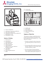
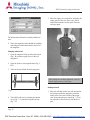
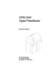
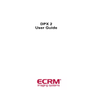
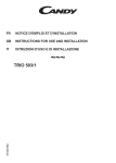
DPX System
Operating Instructions
555 Theodore Fremd Ave., Rye, NY 10580 • 914-925-3261 • http://techsupport.mitsubishiimaging.com Purup-Eskofot A/S
Copenhagen Division
Industriparken 35-37
DK-2750 Ballerup
Denmark
Tel.:
Fax.:
(+45) 4473 6666
(+45) 4473 6767
DPX System - Operating Instructions
Doc. No.: 089-202-090
555 Theodore Fremd Ave., Rye, NY 10580 • 914-925-3261 • http://techsupport.mitsubishiimaging.com Whilst every care has been taken in the preparation of this manual, no liability will be
accepted by Purup-Eskofot A/S arising out of any inaccuracies or omissions.
Interference with the equipment besides normal operation and user maintenance described
in the Operating Instructions Manual, must be carried out by a technician, who has been
trained/educated on the equipment in question.
Warning: This equipment generates, uses, and can radiate radio frequency energy and if
not installed and used in accordance with the Service Manual, may cause interference to
radio communications. It has been tested and found to comply with the limits for a Class A
computing device pursuant to Subpart J of Part 15 of FCC Rules, which are designed to
provide reasonable protection against such interference when operated in a commercial
environment. Operation of this equipment in a residential area is likely to cause interference in which case the user at his own expense will be required to take whatever measures
may be necessary to correct the interference.
This document contains information proprietary to Purup-Eskofot A/S Any disclosure or
use of this information or any reproduction of this document for other than the specific
purpose for which it is intended is expressly prohibited except as Purup-Eskofot A/S may
otherwise agree to in writing.
555 Theodore Fremd Ave., Rye, NY 10580 • 914-925-3261 • http://techsupport.mitsubishiimaging.com 555 Theodore Fremd Ave., Rye, NY 10580 • 914-925-3261 • http://techsupport.mitsubishiimaging.com Table of Contents
DPX System Operating Instructions
Contents
Description . . . . . . . . . . . . . . . . . . . . . . . . . 2
Computer-to-Plate System (CtP)
Time Saving . . . . . . . . . . . . . . . . . . . . . . . . . . . 2
Perfect Accuracy. . . . . . . . . . . . . . . . . . . . . . . . 2
Intelligent Optimization . . . . . . . . . . . . . . . . . . 2
High Quality Register . . . . . . . . . . . . . . . . . . . . 2
Cost-Effective Production . . . . . . . . . . . . . . . . . 2
The DPX SYSTEM Unit
Exterior of Machine . . . . . . . . . . . . . . . . . . . . . 2
Interior of Machine . . . . . . . . . . . . . . . . . . . . . . 3
Sequence of Operation . . . . . . . . . . . . . . . . . . . 3
Basic Operation
Removing/deleting a Job. . . . . . . . . . . . . . . . . . 8
Previewing a Job. . . . . . . . . . . . . . . . . . . . . . . . 8
Connecting to the Front-End . . . . . . . . . . . . . . . 8
Monitoring the RIP . . . . . . . . . . . . . . . . . . . . . . 9
Missing font . . . . . . . . . . . . . . . . . . 9
Missing calibration . . . . . . . . . . . . . . 9
PostScript™ fault . . . . . . . . . . . . . . . 9
Monitoring the DPX SYSTEM Unit
BUSY/INFO. . . . . . . . . . . . . . . . . . 9
INFO
. . . . . . . . . . . . . . . . . . 9
ERROR
. . . . . . . . . . . . . . . . . . 9
FAIL
. . . . . . . . . . . . . . . . . . 10
TEMPERATURES . . . . . . . . . . . . . . 10
Starting the DPX SYSTEM . . . . . . . . . . . . . . . 5
Shutting Down the DPX SYSTEM . . . . . . . . . . 5
Changing Plate Material. . . . . . . . . . . . . . . . 10
RIP Display
Developer Unit
Program Manager . . . . . . . . . . . . . . . . . . . . . . . 6
RipManager . . . . . . . . . . . . . . . . . . . . . . . . . . . 6
RipMate . . . . . . . . . . . . . . . . . . . . . . . . . . . . . . 6
PlateSetter Monitor . . . . . . . . . . . . . . . . . . . . . . 6
Draining the Developer Unit . . . . . . . . . . . . . 13
Cleaning of the Developer Unit . . . . . . . . . . . 14
Output Controller
Active Queue . . . . . . . . . . . . . . . . . . . . . . . . . . 7
Held Queue. . . . . . . . . . . . . . . . . . . . . . . . . . . . 7
Job Names . . . . . . . . . . . . . . . . . . . . . . . . . . . . 7
Start/stop processing
Stop Output . . . . . . . . . . . . . . . . . . 7
Start Output . . . . . . . . . . . . . . . . . . 7
Repeating a Job. . . . . . . . . . . . . . . . . . . . . . . . . 8
Emptying Punch Waste . . . . . . . . . . . . . . . . 13
Filling of the Developer Unit
Troubleshooting
Error messages . . . . . . . . . . . . . . . . 16
Technical Specifications . . . . . . . . . . . . . . 20
DPX SYSTEM Digital Platesetter. . . . . . . . . . 20
Integrated Plate Processing Module. . . . . . . . . 20
RIP Module . . . . . . . . . . . . . . . . . . . . . . . . . . 20
Operation Condition . . . . . . . . . . . . . . . . . . . . 20
Storage Condition . . . . . . . . . . . . . . . . . . . . . . 20
Page i
555 Theodore Fremd Ave., Rye, NY 10580 • 914-925-3261 • http://techsupport.mitsubishiimaging.com 555 Theodore Fremd Ave., Rye, NY 10580 • 914-925-3261 • http://techsupport.mitsubishiimaging.com DPX System - Operating Instructions
Computer-to-Plate System (CtP)
1.Description
Computer-to-Plate System (CtP)
The DPX SYSTEM digital platesetter produces
press-ready plates for a variety of printing jobs.
The entire process only takes a few minutes and is
carried out in full daylight.
This highly versatile platesetter is capable of managing a variety of colour demands, satisfying a
wide range of imaging needs. The DPX SYSTEM
targets all black and white applications as well as
high-end spot-colour, and quality 4-colour jobs.
Cost-Effective Production
The DPX SYSTEM is a highly productive and
economic solution. The technology has proven to
reduce the processing time by 50%, without compromising the ultimate quality.
The DPX SYSTEM Unit
Exterior of Machine
Time Saving
The DPX SYSTEM bypasses the conventional
film processing stage entirely by integrating functions such as edge-to-edge exposure, plate punching, processing, cutting to size, drying and
stacking, in one compact unit.
A.
B.
C.
D.
On/Off Switch
Lid lock release switch
Lid for plate magazines
Exit tray
Perfect Accuracy
Based on an internal drum imaging device with a
LED laser (670 nm), the DPX SYSTEM offers unmatched image accuracy and repeatability, ensuring that each separation is in register.
Intelligent Optimization
The DPX SYSTEM contains two cassettes, holding up to 61 metres of material each. If the same
material is loaded in both cassettes, the unit will
automatically switch to the second cassette when
the first is empty, allowing uninterrupted production for hours.
High Quality Register
Fig. 3
An internal register punch system is optional.
Page 1
555 Theodore Fremd Ave., Rye, NY 10580 • 914-925-3261 • http://techsupport.mitsubishiimaging.com The DPX SYSTEM Unit
DPX System Operating Instructions
M. Activator tank
N. Activator thermo sensor
Fig. 2
E.
F.
G.
H.
I.
K.
Processor module door
Locking pawl for processor module door
Plate exposure module door
Locking pawl for plate exposure module door
Roll magazine 2 (rear)
Roll magazine 1 (front)
Interior of Machine
A
B.
C.
D.
E.
F.
G.
Roll magazine 1
Roll magazine 2
Material load sensors
Empty roll sensors
Drum exit jam sensor
Imagesetting drum
Imagesetter, laser optics and mirror
(Flying spot system)
H. Cutter (Knife)
J. Drum sensor
K. Drum exit guide and switch
L. Buffer
Fig. 3
O.
P.
Q.
R.
S.
Stabilizer tank
Dryer module
Dryer thermo sensor
Plate exit collection ramp
Exit sensor
Sequence of Operation
The operation is computer controlled based on input from sensors that monitor the position of the
plate throughout the entire operation, fig. 3 - 6. The
sequence is as follows:
1. The plate is fed from the selected cassette into
the imagesetting drum by the input rollers, fig.
4.
2. The input/output rollers and sensors ensure that
the plate is fed all the way into the drum, where
it is kept in position by vacuum.
3. The correct position of the plate inside the
drum is ensured by input from the drum sensor
to the computer. In this position, the plate is ex-
Page 2
555 Theodore Fremd Ave., Rye, NY 10580 • 914-925-3261 • http://techsupport.mitsubishiimaging.com DPX System - Operating Instructions
posed from left to right by the imagesetter, fig.
3G.
Fig. 4
4. After exposure the plate is guided towards the
drum exit guide, fig. 5. During the forward motion the plate is temporarily stopped, and the
plate is cut.
Basic Operation
6. The plate is carried through the activator and
stabilizer tanks, fig. 6.
Fig. 6
7. The input rollers and sensors are now ready to
feed another plate into the imagesetting drum.
8. The plate is carried through the drying module
and finally delivered onto the exit collection
ramp.
Basic Operation
Starting the DPX SYSTEM
1. Switch on the DPX SYSTEM unit.
2. Switch on the RIP PC.
Fig. 5
5. The drum exit guide is turned to exit position,
allowing the plate to be fed into the buffer, fig.
3L.
DPX SYSTEM should be switched on before the
RIP PC, otherwise the RipManager will be unable
to start. Should this occur, shut down the RIP PC
and start again.
Wait until the following window appears. It may
take up to 3 minutes.
Page 3
555 Theodore Fremd Ave., Rye, NY 10580 • 914-925-3261 • http://techsupport.mitsubishiimaging.com RIP Display
DPX System Operating Instructions
3. Press CTRL + ALT and keep them pressed
while pressing the DELETE key.
The Log-In screen will appear ensuring the correct
setup. The default setup is normally the correct
one. If this default setup is incorrect, please contact
your local support engineer.
3. Click the Shut down radio button and then the
OK button.
4. Press Enter.
The system automatically starts up.
4. Click the YES button.
5. Switch off the computer and the DPX SYSTEM unit, when a message to do so is displayed.
Shutting Down the DPX SYSTEM
1. Double click on the Program Manager icon.
RIP Display
The DPX SYSTEM unit has no display, because
all settings and operations are made from the RIP
PC. The following screen shows the factory settings (the default settings) of the DPX SYSTEM.
2. Select Shut down from the file menu.
Page 4
555 Theodore Fremd Ave., Rye, NY 10580 • 914-925-3261 • http://techsupport.mitsubishiimaging.com DPX System - Operating Instructions
Output Controller
RipMate
The RipMate handles communication to the frontend, interprets PostScript and sends the plates
through the DPX SYSTEM unit.
PlateSetter Monitor
The Rip Monitor displays the state and progress of
the functions of the machine. For detailed information, please refer to the section “Monitoring DPX
SYSTEM”.
During normal operation 4 programmes are
needed.
Program
Manager
RipManager
RipMate
PlateSetter
Monitor
Output Controller
Using the Output Controller the operator controls
which and when a specific plate is to be processed
or re-exposed.
The above icons represent the available programmes, and each programme can display one or
more windows on the screen.
Program Manager
The Program Manager in Windows NT manages
all programmes. If one of the programmes fails to
start, start it by double clicking on the program
icon.
RipManager
This programme handles all media and cassette information, including loading and unloading the
material. The programme is only used when
changing material or editing media and cassette information is required.
The Output Controller window is part of the RipMate programme.
1. If the above window does not appear, select
Output Controller... from the Output pull-down
menu.
Page 5
555 Theodore Fremd Ave., Rye, NY 10580 • 914-925-3261 • http://techsupport.mitsubishiimaging.com Start/stop processing
DPX System Operating Instructions
To make the Output controller window active,
click on it or open it as described in the section
“Output Controller”.
1. Point at Disable Output and press the left
mouse button.
Active Queue
Stop Output
This queue shows all jobs ready for processing.
The jobs will be processed in top-down order.
Held Queue
Start Output
This queue shows already processed jobs and the
jobs which have generated an error. A black dot
next to the job name indicates an error has occured.
Check the RIP Monitor for error message.
Job Names
The name of the job received by the front-end. After the name the colour is displayed:
[K] Black
[M] Magenta
[Y] Yellow
[C] Cyan
[?] The name of the spotcolor.
When the output is stopped it is still possible to
receive and interpret jobs from the front-end. The
plates received from the front-end will merely be
placed in the Active Queue.
Repeating a Job
Start/stop processing
1. To make the Output Controller window active,
click on it or open it as described in the section
“Output Controller”.
2. In the Held Queue point the mouse at the job to
be repeated.
Page 6
555 Theodore Fremd Ave., Rye, NY 10580 • 914-925-3261 • http://techsupport.mitsubishiimaging.com DPX System - Operating Instructions
3. Press the left mouse button and hold it down
while pulling the job from the Held Queue to
the Active Queue. Release the mouse button.
The job has now been moved from the Held Queue
to the Active Queue and will be exposed according
to its position in the queue.
By placing the job at the top of the Active Queue,
it will be exposed before the other plates.
Removing/Deleting a Job
1. To make the Output Controller window active,
click on it or open it as described in the section
“Output Controller”.
2. Point at the job in the Held Queue which
should be removed and press the left mouse
button down.
3. Click on the Remove button and the job will
disappear.
Removing/Deleting a Job
Previewing a Job
1. To make the Output controller window active,
click on it or open it as described in the section
“Output Controller”.
2. Point at the job in the Held Queue which
should be previewed and press the left mouse
button down.
3. Click on the Roam button.
The job is displayed on the screen in 1:1 (one pixel
on the screen represents one pixel on the plate).
By clicking on the Reduce Roam button, a zoom
effect is achieved.
Connecting to the Front-End
In order to enable the front-end to send jobs to the
RIP, the Input Queue must be started.
1. If the menu entry called Input Queue is present
in RipMate, the connection to the front-end is
already established.
4. Click the YES button, if the job should be deleted.
By holding the Shift key down while selecting, a
range of plates can be selected, and by holding
down the Ctrl key, several individual plates can be
selected.
Page 7
555 Theodore Fremd Ave., Rye, NY 10580 • 914-925-3261 • http://techsupport.mitsubishiimaging.com Monitoring the RIP
DPX System Operating Instructions
Missing calibration
A selected calibration is no longer present.
PostScript™ fault
A bad or too complicated PostScript file has been
sent.
Monitoring the DPX SYSTEM Unit
BUSY/INFO
Information about which function the DPX SYSTEM is performing at a given point of time.
2. Otherwise, select Start Inputs from the RipMate menu in RipMate.
The above example shows the DPX SYSTEM in
stand-by mode with no plates being processed.
The connection to the front-end will now be established.
INFO
The boxes in the INFO window work as a status
bar showing the position of the plates.
Monitoring the RIP
The RipMonitor/System Monitor displays a log of
the RIP as shown below.
Lo: Plate loading. The plate is being fed from roll
magazine A or B into the drum.
Ex: Exposure Cut. The knife is cutting the plate.
Fe: The plate is being fed from the drum into the
buffer.
P1: The plate is in the activator tank.
P2: The plate is in the stabilizer tank.
1. If the above window does not appear, select
Rip Monitor from the RipMate pull-down
menu.
Dry: The plate is in the drying module.
The most important error messages are:
ERROR
If an error/fault occurs, this window will inform
about the cause of the problem.
Missing font
The name of the missing font.
Interlock: The processor door is not closed.
Page 8
555 Theodore Fremd Ave., Rye, NY 10580 • 914-925-3261 • http://techsupport.mitsubishiimaging.com DPX System - Operating Instructions
Liquid Level: The level in the activator tank is to
low. Change the chemistry or refill the replenishment bottles
Drive Load: The processor stopped due to over-
load of the processor motor. Check whether there
is a plate in the processor section.
Dryer Exit: Jam in the processor section. Open the
processor and make sure that no plates are
jammed.
Loader Jam: Jam in the exposure section. The
fault numbers refer to the following:
Fault number 0-100: Something in the exposure
section went wrong during a sequence. Shutting
down the system, remove any plate pieces in the
drum, and restart the system.
Fault number 110-112: A jam in the punch tools.
Shut the system down and clean the tools before
restarting the system.
If a plate jam error occurs, shut down the system,
remove the jammed plate before restarting the
system. If plate jam reoccurs, contact the local
service engineer.
FAIL
Vaccum fail: The vaccum level was incorrect. Ex-
amine the plate and repeat the job if necessary. If
the fail reoccurs, contact the local service engineer.
Activator temp: The temperature deviates more
than 2°C from the specified developer temperature.
Do not process a plate until the temperature is correct.
Dryer Temp: The dryer temperature deviates more
than 2°C from the specified dryer temperature. The
Changing Plate Material
plates might not be completely dry when they
come out.
Drive Tacho: The processor is not running. Check
the processing section for jams, and make sure the
activator and stabilizer tanks are not covered with
dirt. If everything seems in order, and the processor
is still not running, contact the local service engineer.
Temperatures
Indicates the actual temperature in the activator
tank and in the drying unit.
Changing Plate Material
Unloading material
The following description set forth that the system
is installed and setup according to the installation
instructions and user guide.
1. Stop processing by activating the Disable output button. See section “Start/stop processing”.
2. Activate the RipManager icon by double clicking on it.
3. Select Media Management from the DPX
SYSTEM pull-down menu.
The following window appears:
Page 9
555 Theodore Fremd Ave., Rye, NY 10580 • 914-925-3261 • http://techsupport.mitsubishiimaging.com Changing Plate Material
DPX System Operating Instructions
5. Place the empty core on the floor, and place the
empty spool on top of it. Take a new roll of
material and mount it on the spool. Place the
end caps again.
The information reflects the currently loaded cassette.
4. Select the magazine which should be loaded by
activating the small radio button to the left of
the magazine.
Changing material roll
1. Open the magazine lid by pressing the switch
(fig.1, B) in order to gain access to the roll
magazines.
2. Open the front or rear magazine door (fig. 2,
K/I).
3. Take out the spool shaft from the magazine.
If the endcaps are not firmly tightened, it may affect the edge accuracy of the image.
Loading material
Fig 5
4. Take off the old core by releasing the thumb
screw (fig. 7, A), and removing the end cap
(fig. 7 C).
1. Place the roll shaft with a new roll mounted in
the bearings inside the magazine so that the
thumb screw faces the left side of the magazine. Ensure that the gear wheel (fig. 7, E) on
the right side is fitted correctly into the drive
gear.
Page 10
555 Theodore Fremd Ave., Rye, NY 10580 • 914-925-3261 • http://techsupport.mitsubishiimaging.com DPX System - Operating Instructions
Changing Plate Material
5. Press OK button to save the changes.
The rolls in the magazine which are about to be
loaded will now start running. They will run for 30
seconds which allows the operator plenty of time
to align the material.
2. If the length is zero enter the number of metres
just loaded.
6. Remove the white tape from the roll and position the leading edge of the roll at the nip of the
inlet rollers at the bottom of the magazine.
Guide the leading edge of the roll into the nip
of the feed rollers. When the plate starts feeding into the inlet rollers, close the magazine
cover and the lid.
If removing the tape and aligning the material
takes more than 30 seconds, just click the LOAD
button once again.
3. Use the mouse to click on the Load button in
order to start the inlet roller drive motor.
The emulsion side is matt and dark and faces
downwards on the roll. It is important that the
front edge of the plate material is not folded or
creased and that all tape has been carefully removed.
If length (M) is zero, the lenght of the material
should be specified, otherwise the loading process
will generate an error.
Wait for the material to load.
4. Press YES to LOAD the material.
When a new roll has been fitted, the first 2-3 plates
cannot be used because of possible fogging during
installation.
Page 11
555 Theodore Fremd Ave., Rye, NY 10580 • 914-925-3261 • http://techsupport.mitsubishiimaging.com Emptying Punch Waste
DPX System Operating Instructions
7. Click Form Feed.
8. Click YES to form feed a plate.
Repeat the last two steps until all exposed material
is fed.
3. Pull out the waste box as shown by turning the
small key on the front of the box.
9. Click OK.
4. Start the system as described in the section
“Starting the DPX SYSTEM”
10. Iconise the RipMagager by clicking the following button in the upper right corner.
Developer Unit
11. To expose, start processing again. See section
“Start/stop processing”.
Emptying Punch Waste
If the DPX SYSTEM is equipped with a punch
tool, the punch waste box must be emptied after
every 1,000 plates.
Draining the Developer Unit
When the processor module door is open-ed, the
power is automatically shut off.
1. Open the processor module door (fig. 2, E).
2. Lift the locking pawl of the processor unit and
pull the section forward to the extreme stop position.
1. Shut down the system as described in the section “Shutting down the DPX SYSTEM”
3. Lift off the two replenishment bottles.
2. Open the plate exposure module door (fig. 2,
G).
4. Carefully pull out the thermostat from the
housing in the processor tank.
Page 12
555 Theodore Fremd Ave., Rye, NY 10580 • 914-925-3261 • http://techsupport.mitsubishiimaging.com DPX System - Operating Instructions
Developer Unit
5. Unplug the cable for the heating element underneath the processor module.
6. Release the draining hoses and insert each one
into a separate empty container. Open the taps.
2. Remove the grid on the dryer section.
3. Each processor rack can be lifted approx. 3 cm
at the front and pulled out approx. 5 cm, thus
releasing the gear wheels from the drive unit at
the back.
7. When the unit is empty, shut off the taps and fit
the hoses into their holders.
Before filling the empty tanks with new chemistry
they should be cleaned.
Cleaning of the Developer Unit
The processor module should be cleaned every
time the chemistry is changed. The processor module must be drained and released (see “Draining
the developer unit”).
1. Remove the tank covers.
Page 13
555 Theodore Fremd Ave., Rye, NY 10580 • 914-925-3261 • http://techsupport.mitsubishiimaging.com Filling of the Developer Unit
4. Lift the two processor racks from the tanks and
clean them with a soft brush and lukewarm
water.
DPX System Operating Instructions
3. Remove the cover of the processor module to
gain access to the two processor tanks.
4. Close the draining hose taps.
5. Pour 16 litres of stabilizer liquid into the righthand tank and approx. 1 litre into the blackcapped replenishment bottle.
Important: Avoid any splashing into the activator
tank as even small amounts of stabilizer will destroy the activator.
5. Clean the activator and stabilizer tanks by
pooring clean water into the tanks while the
draining hoses is open.
6. Let the water run off the racks before replacing
them in the tanks.
7. Put the racks back in the tanks and replace the
grid on the dryer section.
Filling of the Developer Unit
When the rear right door is opened, the power to
the heating element in the activator tank is automatically shut off.
1. Open the front cover of the processor module
by activating the locking pawl at the bottom of
the rear right door.
2. Pull the carriage with the processor module
forward to the extreme stop position. Lift off
the two replenishment bottles.
6. Pour 16 litres of activator liquid into the lefthand tank and approx. 1 litre into the bluecapped replenishment bottle.
7. Replace the cover on the processor section and
place the replenishment bottles in their holders.
8. Gently slide the processor module back into
position and close the door.
9. The activator temperature is regulated by
means of a computer-controlled heating element and must be between 20°C (68°F) and
30°C (86°F).
Page 14
555 Theodore Fremd Ave., Rye, NY 10580 • 914-925-3261 • http://techsupport.mitsubishiimaging.com DPX System - Operating Instructions
Warning: Never turn on the power unless the
processor module is filled or the power plug for
the heating element is removed, as this may cause
overheating and damage to the processor module.
Troubleshooting
Imagesetter not found
If “Imagesetter not found” is displayed in the RipManager window during startup, the DPX SYSTEM does not report on the SCSI chain.
Troubleshooting
1. Check that the door to the plate exposure module door (fig 2. E) is closed.
Error messages
2. Try shutting down the system and restarting it.
See section “Shutting down the DPX SYSTEM”.
The DPX SYSTEM displays error messages in the
Output Controller and in the PlateSetter Monitor.
Look for the error messages and refer to this section for troubleshooting.
The RipManager and RipMate will not start up
Whenever the RipManager starts up it searches for
the DPX SYSTEM unit through the SCSI chain. If
it is unable to find the DPX SYSTEM unit or if
there is an error on the DPX SYSTEM unit the
RipManager does not start. Because the RipManager is iconised it is not possible to see exactly
which error occurred. To display an error message
do the following:
If the DPX SYSTEM unit is not switched on before the RIP PC, this error message will occur.
Cover open
The cover to the plate processing module door (fig
2. E) is not closed.
Close the door (fig 2. E).
Double click on the RipManager icon in the programme manager to launch the RIP again.
1. Double click on the Program Manager icon.
Interface card failed
The connection through the SCSI Interface cable is
lost, and the RIP cannot communicate with the
DPX SYSTEM.
2. Find the RipManager programme group.
1. Shut down the system as described in section
“Shutting down the DPX SYSTEM”
2. Start the DPX SYSTEM as described in “Starting the DPX SYSTEM”
3. Double click on the RipManager icon.
The error message will now be displayed. Refer to
the Troubleshooting section for further help.
Printer caught up
RipMate has not had the necessary system resources to transfer image data to the DPX SYS-
Page 15
555 Theodore Fremd Ave., Rye, NY 10580 • 914-925-3261 • http://techsupport.mitsubishiimaging.com Troubleshooting
DPX System Operating Instructions
TEM, due to Windows NT system or another
programme.
1. Try repeating the job.
Undefined command “set calibration”
The current plate setup can not find a calibration.
This might be due to the setup of the calibration or
how the received PostScript job was set up. Refer
to the RipMate user guide for further information.
Font not found
The system is set up to refuse processing a plate
when a font is missing in the PostScript job.
4. Look for plate material left in the drum.
DPX SYSTEM reports to the Rip Monitor which
font is missing.
Loader Jam: 0 - 100
An error in the exposure section of the DPX SYSTEM has occured. Generally, this error message
describes a situation, where a sensor has not seen
the material passing by at the expected time.
5. With the palm of the hand against the drum
surface, scan the surface to make sure that no
pieces are left.
6. Close the exposure module door (fig. 2. G),
and restart the system.
Loader Jam: 101 - 112
1. Shut down the system and restart it.
Continue exposing if the error has disappeared,
otherwise
2. Shut down the system.
3. Open the exposure module door (fig. 2. G).
Warning: All power to the machine is now shut
off. Wait 20 seconds for the spinner motor to settle.
This error only occurs when a punch system is installed.
1. Shut down the system.
2. Open the exposure module door (fig 2. G).
Warning: All power to the machine is now shut
off. Wait 20 seconds for the spinner motor to settle.
Page 16
555 Theodore Fremd Ave., Rye, NY 10580 • 914-925-3261 • http://techsupport.mitsubishiimaging.com DPX System - Operating Instructions
Troubleshooting
If the processor unit cannot be pulled out, a plate is
jammed either between the buffer and the processor unit or between the exit tray and the processor
unit.
Use the long jam knife (mounted on the inside of
the exposure module door) to cut the jammed plate
from one of the following holes:
3. Check the two punch tubes and punch tools for
punch waste. Make sure they can move freely
by turning them by hand.
4. Close the exposure module door (fig 2. G), and
restart the system.
Dryer exit
A plate is jammed in the processing section.
3. Take out the two replenishment bottles.
1. Open the processor module door (fig 2. E).
4. Lift off the tank cover and check for plates in
the racks. If one is found remove it.
2. Lift the locking pawl of the processor unit and
pull the section forward to the extreme stop position
If no plate is found in the tanks, look in the dryer
section.
Page 17
555 Theodore Fremd Ave., Rye, NY 10580 • 914-925-3261 • http://techsupport.mitsubishiimaging.com Troubleshooting
DPX System Operating Instructions
6. Lift off the air guide.
5. Lift the dryer module as shown on the picture.
Check if there is a plate in the dryer section. If not,
close the exposure module door (fig. 2. E) and continue exposing.
Warning: Observe closely the mounting of the
two guides. If they are not put back in exactly the
same position, it might cause a jam.
7. Lift off the material guide.
When all guides are removed the operator can
freely remove any jammed material.
8. Mount the two guides in position again and
close the dryer module.
9. Close the processor module door (fig 2. E) and
continue exposing.
Page 18
555 Theodore Fremd Ave., Rye, NY 10580 • 914-925-3261 • http://techsupport.mitsubishiimaging.com DPX System - Operating Instructions
2.Technical
Troubleshooting
Specifications
DPX SYSTEM Digital Platesetter
Operation Condition
Type:
Max. plate format:
Max. image/
exposure area:
Imaging technology:
Light source:
Plate material:
Resolution:
Screen ruling:
Digital Plate Exposure System
460 x 550 mm / 16.5 x 21.6"
Operation temperature range: 18°C-28°C
Humidity:
25% - 80% RH non condensing
436 x 546 mm / 16.3 x 21.4"
Internal drum
670 nm visible red laser diode
Photo-direct polyester plates
900 - 2540 dpi (variable)
56 - 175 lpi (determined by the
plate material and press)
5 - 95%
Storage Condition
Dot Range:
Image size
repeatability:
Image positioning
repeatability:
Operation temperature range: 5°C-50°C
Humidity:
25% - 80% RH non
condensing
± 1/100 mm
± 0.5 mm related to edge
± 0.2 mm related to punch
Material loading:
Two supply cassettes
Dimensions (WxHxD):
1020 x 1055 x 1366
mm
Weight:
454 kg
Power Consumption: 13 Amp. without punch, 16
Amp. with punch
Optional:
Register Punch System (landscape and/or portrait punch)
Integrated Plate Processing Module
Principle:
Processor:
Dryer:
Replenishment:
Stacking:
Variable speed
Activator and stabilizer
Temperature controlled, hot air
Level control
50 - 100 plates
RIP Module
System:
Features:
Network:
Interface:
Windows NT hosted
Harlequin Core (Script-Works)
HPS screening
Postscript level 2
Compatible with PC , Macintosh and UNIX networks
Standard SCSI -2 Differential.
Page 19
555 Theodore Fremd Ave., Rye, NY 10580 • 914-925-3261 • http://techsupport.mitsubishiimaging.com 555 Theodore Fremd Ave., Rye, NY 10580 • 914-925-3261 • http://techsupport.mitsubishiimaging.com