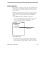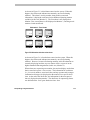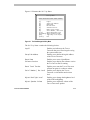
1
View Manager® 96 Version 5
with Enhanced TOUCH TRACKER®
System Operator’s Manual
8000-2635-05 B
Survey
Did this document help you do your job? Please complete this short survey by circling the number that best matches your
opinion of each statement. Also, give us your comments on how we could improve items you rate 3 or lower. Provide
examples, if necessary. Your input will help us improve this information.
Thank you for your time.
Strongly
Agree
Agree
Neither
Agree /
Disagree
Disagree
Strongly
Disagree
Not
Applicable
1. Document covered what I needed to
know.
5
4
3
2
1
N/A
2. It was easy to find information.
5
4
3
2
1
N/A
3. Difficult concepts were explained
well.
5
4
3
2
1
N/A
4. Pictures and examples helped.
5
4
3
2
1
N/A
5. Information was accurate.
5
4
3
2
1
N/A
6. The index helped.
5
4
3
2
1
N/A
7. The print quality of document is
acceptable.
5
4
3
2
1
N/A
Very
Good
Good
Fair
Poor
N/A
What do you think?
8. My overall rating for this document is: Excellent
If you rated an item 3 or lower, please tell us why.
Your Name (optional) _________________________________
Mailing Address _______________________________________________________
Phone (____)______________
Quality Improvement Survey
8000-2635-05, Rev. B
NO POSTAGE
NECESSARY
IF MAILED
IN THE
UNITED STATES
BUSINESS REPLY MAIL
F I RST - CL A SS
MAI L
PERM I T
N O.
23 44
B OCA
RATON ,
F L OR I DA
POSTAGE WILL BE PAID BY ADDRESSEE
SENSORMATIC ELECTRONICS CORPORATION
ATTN: TECHNICAL COMMUNICATIONS / MS C-65
PO BOX 5037
BOCA RATON, FLORIDA 33431-9714
1.
FOLD HERE
You can return this form by Fax, E-mail or Mail
Fax:
Send to: Mike Joyner, Manager
Technical Communications Department
Fax Number: (561) 989-7548
E-mail:
Send comments to:
[email protected]
Mail:
Fold this form on the dotted line, seal it with transparent tape,
and send it to the address printed above.
2.
APPLY TRANSPARENT TAPE HERE
A
B
Ac
tvt
y
Ph
o to
Me
nu
C
1
VC On
R
Off
2
Vie
w
5
6
7
Op
en
Lo
D
3
4
Cle
En ar
try
Iris
Clo
se
Pat
8
ck
Zon
9
rn
e
Se
q
0
Ho ld
Pre
v
Ne
xt
Hel
p
Ala
rm
Ack
View Manager 96
®
System Operator’s Manual
with Enhanced TOUCH TRACKER
Version 5.0
EQUIPMENT MODIFICATION CAUTION
Equipment changes or modifications not expressly approved by Sensormatic Electronics Corporation,
the party responsible for FCC compliance, could void the user's authority to operate the equipment and
could create a hazardous condition.
FCC COMPLIANCE
This equipment complies with Part 15 of the FCC rules for Class A digital devices when installed and
used in accordance with the instruction manual. Following these rules provides reasonable protection
against harmful interference from equipment operated in a commercial area. This equipment should not
be installed in a residential area as it can radiate radio frequency energy that could interfere with radio
communications, a situation the user would have to fix at their own expense.
WARRANTY DISCLAIMER
Sensormatic Electronics Corporation makes no representation or warranty of the contents of this
manual and disclaims any implied warranties of merchantability or fitness. Sensormatic Electronics
Corporation reserves the right to revise this manual and change its content without obligation to notify
any person of these revisions.
LIMITED RIGHTS NOTICE
For units of the Department of Defense, all documentation and manuals were developed at private
expense and no part of it was developed using Government Funds. The restrictions governing the use
and disclosure of technical data marked with this legend are set forth in the definition of "limited
rights" in paragraph (a) (15) of the clause of DFARS 252.227.7013. Unpublished - rights reserved
under the Copyright Laws of the United States.
SOFTWARE LICENSE AGREEMENT
A Software License Agreement appears in Appendix A of this manual. Please read it carefully. Using
the View Manager 96 system software indicates that you accept the terms and conditions of this
agreement.
Copyright 2001
All rights reserved.
No part of this manual may be reproduced in any form without written permission from Sensormatic®
Electronics Corporation.
Sensormatic and the Sensormatic logo are registered trademarks of Sensormatic Electronics
Corporation.
Product names mentioned herein may be trademarks or registered trademarks of other companies.
PN- 8000-2635-05, Rev. B
BSL-04/2001
A
B
Ac
tvt
y
Ph
o to
Me
nu
C
1
VC On
R
Off
2
Vie
w
5
6
7
Op
en
Lo
D
3
4
Cle
En ar
try
Iris
Clo
se
Pat
8
ck
Zon
9
rn
e
Se
q
0
Ho ld
Pre
v
Ne
xt
Hel
p
Ala
rm
Ack
Table of Contents
BEFORE YOU BEGIN ..................................................................................VII
What Is In This Manual ..................................................................................................... viii
Text Conventions................................................................................................................ ix
Related Documents ............................................................................................................ ix
View Manager 96 Support Services ................................................................................... x
Getting System Training And Consultation Services ......................................................... x
CHAPTER 1: ABOUT VIEW MANAGER 96................................................ 1-1
Your Role As A View Manager 96 System Operator ......................................................1-2
View Manager 96 Features ...............................................................................................1-2
View Manager 96 Equipment ...........................................................................................1-4
Equipment That Operators Use ......................................................................................1-4
Equipment that Controls View Manager 96 ....................................................................1-6
Other Equipment.............................................................................................................1-6
CHAPTER 2: GETTING STARTED WITH VIEW MANAGER 96 ................ 2-1
Using Passwords ..............................................................................................................2-2
Logging On Using the TOUCH TRACKER ..........................................................................2-2
Logging Off the TOUCH TRACKER ....................................................................................2-3
How Passwords Restrict Access ....................................................................................2-4
Information Displayed on the Monitor ............................................................................2-5
Dedicated Monitors...........................................................................................................2-6
CHAPTER 3: USING THE ENHANCED TOUCH TRACKER ...................... 3-1
Introducing the Enhanced TOUCH TRACKER ....................................................................3-2
Performing Basic TOUCH TRACKER Operations ...............................................................3-3
Selecting a Monitor .........................................................................................................3-3
Selecting a Camera ........................................................................................................3-4
Controlling Pan and Tilt...................................................................................................3-5
“Flipping” the SpeedDome ..............................................................................................3-6
Controlling Zoom and Focus...........................................................................................3-6
Controlling the Iris ...........................................................................................................3-7
Locking Out Other Users ................................................................................................3-8
Controlling a VCR ...........................................................................................................3-9
Performing Advanced TOUCH TRACKER Operations......................................................3-10
Displaying a Quick View................................................................................................3-10
Running a Pattern .........................................................................................................3-11
Running a Sequence.....................................................................................................3-13
Calling a Zone ...............................................................................................................3-19
Initiating an Activity........................................................................................................3-19
Toggling an Output .......................................................................................................3-22
Clearing an Alarm .........................................................................................................3-23
Recalling Camera Commands......................................................................................3-24
Displaying Help Information ..........................................................................................3-25
Accessing the User’s Menu ...........................................................................................3-25
CHAPTER 4: USING THE ON-SCREEN USER’S MENU ........................... 4-1
Introducing the View Manager 96 User’s Menu .............................................................4-2
Accessing the User’s Menu .............................................................................................4-3
Moving Around the Screen ..............................................................................................4-5
Moving the Highlight Bar .................................................................................................4-5
Selecting an Item ............................................................................................................4-6
Exiting from the User’s Menu ..........................................................................................4-6
Calling Up a Camera .........................................................................................................4-7
Defining and Displaying Quick Views.............................................................................4-8
Defining a Quick View.....................................................................................................4-8
Displaying a Quick View................................................................................................4-11
iv
View Manager 96 Operator’s Manual
Defining and Running Patterns .....................................................................................4-12
Defining a Pattern .........................................................................................................4-12
Special Note for SpeedDome LT Auto Pan Programming............................................4-17
Running a Pattern .........................................................................................................4-18
Running a Sequence ......................................................................................................4-20
Calling a Zone .................................................................................................................4-21
Initiating Activities ..........................................................................................................4-23
CHAPTER 5: RESPONDING TO SYSTEM ALARMS ................................. 5-1
What Is an Alarm?.............................................................................................................5-2
General Versus Alarming Monitors.................................................................................5-3
How Do You Know When an Alarm Occurs? .................................................................5-4
How Do Priorities Affect Alarms?....................................................................................5-5
How the System Handles Incoming Alarms ...................................................................5-6
Responding to Alarms....................................................................................................5-11
CHAPTER 6: ENHANCED TOUCH TRACKER UTILITIES......................... 6-1
What Are TOUCH TRACKER Utilities? .................................................................................6-2
Entering the Utility Mode..................................................................................................6-2
Logging Off the System ...................................................................................................6-4
Setting Up the TOUCH TRACKER Link Address.................................................................6-4
Resetting the SpeedDome ...............................................................................................6-6
Displaying the Software Version .....................................................................................6-7
Resetting the TOUCH TRACKER ..........................................................................................6-8
Displaying the TOUCH TRACKER’s Serial Number and Revision Level ..........................6-9
Adjusting the LCD Backlighting ......................................................................................6-9
Adjusting the Key Click Sound........................................................................................6-9
Turning the Key Click On or Off ....................................................................................6-10
Exiting the Utility Mode ..................................................................................................6-10
APPENDIX A: SOFTWARE LICENSE AGREEMENT.................................A-1
Table of Contents
v
vi
View Manager 96 Operator’s Manual
A
B
Ac
tvt
y
Ph
o to
Me
nu
C
1
VC On
R
Off
2
Vie
w
5
6
7
Op
en
Lo
D
3
4
Cle
En ar
try
Iris
Clo
se
Pat
8
ck
Zon
9
rn
e
Se
q
0
Ho ld
Pre
v
Ne
xt
Hel
p
Ala
rm
Ack
Before You Begin
The View Manager 96 System Operator’s Manual provides detailed
information about View Manager 96 features, operation, and application. It
explains step-by-step the tasks that you will perform when using the View
Manager 96 system. It is designed to be a continuing source of information
and reference as you use your View Manager 96 system.
In This Chapter
·
·
·
·
What Is In This Manual
Text Conventions
Related Documents
View Manager 96 Support Services
What Is In This Manual
This manual is organized as follows:
viii
·
Chapter 1: “About View Manager 96,” describes what View Manager 96
does and how it is used. It also identifies the equipment installed and
used with a View Manager 96 system, and briefly discusses your role as
a View Manager 96 operator.
·
Chapter 2: “Getting Started With View Manager 96,” describes how to
log on and off the TOUCH TRACKER. This chapter also discusses the
significance of passwords and how they affect your access to the system.
In addition, it tells about the information displayed on the monitor when
you start the system.
·
Chapter 3: “Using the TOUCH TRACKER,” discusses how you use the
TOUCH TRACKER to perform View Manager 96 operations—from basic
camera control to advanced automated operations.
·
Chapter 4: “Using the On-screen Menus,” discusses the options available
to you on the User’s Menu and provides instructions on how to use these
options.
·
Chapter 5: “Responding to System Alarms,” briefly explains what an
alarm is and how you recognize when an alarm is active. It describes
how the system handles multiple alarms, and how you acknowledge and
subsequently clear an alarm.
·
Chapter 6: “TOUCH TRACKER Utilities,” describes those system utilities
that can be implemented from the TOUCH TRACKER, and provides
instructions on how to use those utilities.
View Manager 96 Operator’s Manual
Text Conventions
This book uses text in different ways to identify different kinds of
information.
Note
italics
Terms specific to View Manager 96 and text that requires
emphasis.
monospace
System messages and prompts, names of screens, and
menu selections
bold
Names of buttons on the keypad, for example, Hold
Special notes appear inside a box like this one.
Helpful hints appear like this. Hints contain supplemental information or
alternate methods of performing a task, which may be quicker, easier, or
more efficient.
Related Documents
Other sources provide supplemental information about View Manager 96;
these sources serve to enhance your understanding of the View Manager 96
system and its applications.
·
The View Manager 96 Quick Reference Guide (part number 8000-263605) provides quick reference information about some of the procedures
that are described in detail in this manual. It should be used as a
supplement to—not in place of—the information covered in this manual.
·
The View Manager 96 System Administrator’s Manual (part number
8000-0756-05) provides administration information for the System
Administrator.
Before You Begin
ix
·
Some View Manager 96 systems are used in conjunction with the
POS/EM Value system. The POS/EM Value System Administrator’s
Manual (part number 8000-1488-01) provides instructions on how to use
View Manager 96 to augment the POS/EM Value features.
If you need additional copies of the View Manager 96 System Operator’s
Manual, or any other support documentation, contact your Sensormatic Sales
Representative. The part number for this manual is 8000-2635-05; this is the
number you will use when ordering the manual.
View Manager 96 Support Services
Sensormatic provides a variety of support services to help you get the most
from your View Manager 96 system.
If you have a question about View Manager 96 operation, and you cannot
find the answer in this document, consult your System Administrator. If
your question has not been answered, contact your Sensormatic
representative.
Getting System Training And Consultation Services
If you feel that you require additional training beyond the training that was
administered by the Customer Support Specialist or Customer Engineer,
contact your Supervisor or System Administrator to learn about
supplemental training options.
x
View Manager 96 Operator’s Manual
C H A P T E R
1
A
B
Ac
tvty
Ph
oto
Me
nu
e
C
1
VC On
R
Off
2
Vie
w
5
6
7
Op
en
Lo
D
3
4
Cle
En ar
try
Iris
Clos
Pa
8
ck
trn
Zone
9
Seq
0
Ho ld
Pre
v
Next
Help
Ala
rm
Ack
About View Manager 96
This chapter briefly discusses your role as a View Manager 96 (VM96)
operator. It describes the features and capabilities of the system and
identifies the equipment the VM96 system supports.
In This Chapter
·
·
·
Your Role as a View Manager 96 System Operator
View Manager 96 Features
View Manager 96 Equipment
Your Role As A View Manager 96 System Operator
This manual describes those features available to you as a VM96 operator
and provides specific instructions for using these features. It is up to you,
however, to learn how to use these features effectively in your specific
environment.
Each site and situation has different concerns, capabilities, and
vulnerabilities. Understanding how your system works enables you to
address these concerns and overcome these vulnerabilities.
Use this manual to learn how to customize your system to meet the needs of
your environment. What areas will you need to look at frequently and
quickly? Are there certain doors, hallways, or high-traffic areas that require
frequent surveillance? If so, you can define Quick Views and Patterns of
these areas. Get to know what outputs and Activities you can initiate from
the TOUCH TRACKER. Your System Administrator will be able to help you
familiarize yourself with what functions the TOUCH TRACKER has been
programmed to perform.
Most importantly, get comfortable using the system. The more
knowledgeable you are of the system’s features and functions, the better you
will be able to secure your site. Once you become comfortable using the
system, you will find it a valuable and timesaving security and management
tool.
View Manager 96 Features
The VM96 system enables you to oversee activity throughout your facility
as it happens. This powerful overview allows you to document activity and
can help to prevent unwanted activity from taking place.
VM96 provides one of the most advanced matrix switcher available in the
marketplace to date. Matrix switching allows any camera’s video to be
displayed on any monitor, enabling multiple users to monitor activity at the
same time.
1-2
View Manager 96 Operator’s Manual
Features available to VM96 operators include:
·
Matrix switching (selecting which monitor to display video on, and
which camera to display on that monitor).
·
Single-handed control a camera’s panning and tilting movements, as
well as its zoom, focus, and iris commands.
·
Camera lock feature that prevents other users from controlling the
currently selected camera.
·
SpeedDome flip feature that enables you to rotate the SpeedDome 180°
in the opposite direction where it is currently pointing.
·
The ability to define and display Quick Views, which are immediate
camera call-ups of pre-defined scenes, with automatic zoom and focus.
·
The ability to define and run Patterns, which are sequential series of pan,
tilt, zoom, and focus movements from a single programmable dome.
·
Simultaneous call-up of multiple Quick Views displayed on separate
monitors. This is referred to as a Zone.
·
The ability to trigger an output (e.g., turn on a light, unlock a door, close
a gate, etc.) from the TOUCH TRACKER
·
Immediate Sequence call-up. A Sequence incorporates pre-defined
Patterns, Quick Views, fixed shots, and outputs which run one after the
other on a single monitor.
·
Immediate Salvo call-up. A Salvo incorporates multiple actions (Quick
Views, Patterns, fixed shots, and outputs) which run simultaneously on
separate monitors.
·
The ability to initiate and clear certain Activities that has been created
by the System Administrator.
·
Alarm acknowledgment via the TOUCH TRACKER.
·
VCR on/off function that enables you to switch the VCR from timelapse recording to real-time recording, and vice-versa.
·
Utilities that can be accessed from the TOUCH TRACKER. These utilities
allow you to perform the following tasks: reset the TOUCH TRACKER or
SpeedDome; set the link address for the TOUCH TRACKER: display the
TOUCH TRACKER software version, serial number, and revision level;
About View Manager 96
1-3
adjust the LCD backlight level; adjust the speaker volume; and turn
on/off the key click sound.
·
The ability to display help information about the TOUCH TRACKER
buttons.
View Manager 96 Equipment
Every VM96 system is made up of a unique set of equipment. Some
equipment is required and other equipment is optional. Equipment falls into
one of the following categories:
·
·
·
Equipment that operators use
Equipment that controls the VM96 system
Other equipment
Figure 1-1 shows components typically installed with a VM96 system. This
simplified illustration gives only a very broad overview of the different types
of equipment and how the components connect to one another. Some
components in a VM96 system, such as input devices and output devices,
can number in the hundreds.
Equipment That Operators Use
As a system operator, your first concern is often with the equipment that you
use hands-on. For a VM96 system, this equipment is the TOUCH TRACKER,
the monitors, and the VCRs.
1-4
·
The TOUCH TRACKER is the device you use to control camera movement,
as well as adjust zoom, focus, and iris. With the TOUCH TRACKER you
can access special features such as Quick Views, Patterns, Sequences,
Zones, and Activities, and you can clear system alarms.
·
The video monitor is where the camera’s video is displayed. Some
monitors have text overlay capability; if this is the case, the User’s Menu
and the Utility Menu are displayed on the video monitor. A single
Workstation can include up to eight switched monitors and up to 96
dedicated monitors.
View Manager 96 Operator’s Manual
·
The VCR enables you to record (in real-time) the video on the switched
monitor it is connected to. By pressing the VCR On button on the
TOUCH TRACKER, you switch the VCR from time-lapse to real-time
recording. By pressing the VCR Off button, you switch the VCR from
real-time recording to time-lapse recording.
SpeedDome
I/O Module
Alarm Inputs
and Outputs
SpeedDome
Junction
Box
Fixed
Camera
VM96 Rack Unit
Dedicated Monitors
1
2
3
4
5
6
7
8
9
0
1
2
3
4
5
6
7
8
9
0
1
2
3
4
5
6
7
8
9
0
1
2
3
4
5
6
7
8
9
0
Administrator
Keyboard
VCR
Dedicated Monitors
1
1
1
2
3
4
5
6
7
8
9
1
2
3
4
5
6
7
8
9
2
3
4
5
6
7
8
9
2
3
4
5
6
7
8
9
0
0
0
0
TOUCH TRACKERS 1-4
TOUCH TRACKERS 5-8
Switched Monitors
Figure 1-1:
About View Manager 96
View Manager 96 System Components
1-5
Equipment that Controls View Manager 96
When you use the TOUCH TRACKER, monitor, and VCR, you are actually
communicating with the device that controls the VM96 system. That device
is the Rack Unit.
The Rack Unit is the heart of the VM96 system; it acts as the communication
hub for the entire system. The Rack Unit is where all operator and
administrator programming and data are stored. This box also provides
video matrix switching and system control.
Other Equipment
You may see other types of equipment installed around your site. You might
not operate this equipment directly, but it does play as important a role in
running a VM96 system along with the Rack Unit and the TOUCH TRACKER.
This equipment may include any or all of the following:
1-6
·
The system’s cameras enable you to monitor activity throughout a
facility from a single location. You can see video from up to 96
cameras. The VM96 system is compatible with programmable and nonprogrammable domes, PTZ (pan/tilt/zoom) cameras, and fixed cameras.
·
The Input/Output (I/O) module is an optional device that provides an
additional 32 inputs and 16 relays to the VM96 system. Your system
can have up to nine I/O modules connected, adding a total of 288 inputs
(32 X 9) and 144 relays (16 X 9) to the system. Systems without the I/O
module are limited to the four inputs and four outputs provided on each
programmable dome. The I/O module also accepts alarm
communications from other computer-based systems such as fire alarm
or burglar systems. This makes it possible to provide a video response
to alarms occurring on other systems.
·
Input devices are hardware components that provide an electrical signal
to indicate the state of a device. These devices sense certain conditions
or changes in conditions and send a signal to the programmable camera
or I/O module to which they are connected. For example, a motion
detector is an input device that senses movement. Other examples of
input devices include smoke detectors and twilight sensors.
View Manager 96 Operator’s Manual
·
Output devices are hardware components that can be controlled by the
system. These devices respond to commands sent from the
programmable camera or I/O module they are connected to and perform
an action. For example, an audible alarm is an output device that might
be triggered when the door at an emergency exit is opened. Other
examples of output devices include floodlights and door locks.
About View Manager 96
1-7
NOTES:
1-8
View Manager 96 Operator’s Manual
C H A P T E R
2
A
B
Ac
tvt
y
Ph
o to
Me
nu
C
1
VC On
R
Off
2
Vie
w
5
6
7
Op
en
Lo
D
3
4
Cle
En ar
try
Iris
Clo
se
Pat
8
ck
Zon
9
rn
e
Se
q
0
Ho ld
Pre
v
Ne
xt
Hel
p
Ala
rm
Ack
Getting Started With View Manager 96
This chapter provides information that you need to know before you begin
using the VM96 system. It discusses the significance of passwords and how
they control your level of access to the system. It provides instructions on
how to log on and off the TOUCH TRACKER. In addition, it describes what
you will see displayed on the monitor(s) when you use the system, and
points out the significance of switched versus dedicated monitors.
In This Chapter
·
·
·
·
Using Passwords
How Passwords Restrict Access
Information Displayed on the Monitor
Dedicated Monitors
Using Passwords
Note
If your facility does not have passwords enabled, you will not be required to
log on to the TOUCH TRACKER. This section does not apply to you.
If passwords are enabled at your facility, you will be required to log on to
the TOUCH TRACKER before you can begin using it. When you log on to the
TOUCH TRACKER, you enter your password—via the number buttons—that
was assigned to you by your System Administrator.
Your password tells the TOUCH TRACKER the following information about
you:
·
When you can use the VM96 system.
·
Which cameras you can see video from and control.
·
Whether or not you can define Quick Views and Patterns.
·
Which administration forms (if any) you have access to, and whether or
not you can modify these forms in any way.
Logging On Using the TOUCH TRACKER
As long as the previous user has logged off the TOUCH TRACKER, the LCD
will display this message:
Enter Password?
2-2
View Manager 96 Operator’s Manual
Note
If passwords are enabled, and the LCD does not display this prompt when
you are ready to log on to the TOUCH TRACKER, this means that the previous
user has not logged off. If this is the case, refer to the next section,
“Logging Off the TOUCH TRACKER,” to log that user off before you log on.
When you are ready to log on, use the number buttons to enter your unique
password, and then press the Menu button. Remember that your password
cannot be more than five digits long.
Once you have correctly entered your password, and the system recognizes
you as a valid user, the LCD displays the following information:
Cam
Ax
Designates the Touch
Tracker address.
At this point you may select a specific monitor and camera. Refer to
Chapter 3 for procedures on selecting monitors and cameras.
Do not leave the system unattended while you are logged on to it. Refer to
the following section, “Logging Off the TOUCH TRACKER,” for procedures
on how to log off the TOUCH TRACKER, and remember to do so whenever
you are no longer using it.
Logging Off the TOUCH TRACKER
When you are finished using the TOUCH TRACKER, you must log off. This
tells the system that you are no longer using TOUCH TRACKER, and that no
one should have access to it until the next user logs on.
The following procedure describes how to log off the TOUCH TRACKER.
1. Press number 0 and then the Menu button on the keypad.
The TOUCH TRACKER LCD displays the following prompt:
Utility Mode
Enter Selection
Getting Started With View Manager 96
2-3
2. Press number 1 on the TOUCH TRACKER.
The LCD displays the following prompt:
Press 1 key
To Logoff
3. Press number 1 again.
The LCD displays the following prompt:
Enter Password?
You have successfully logged off the system.
How Passwords Restrict Access
Note
If your facility does not have passwords enabled, this section does not apply
to you.
When using this system, you will find that you may not have access to all
system operations. System Administrators can restrict a user’s access to the
system in three ways:
2-4
·
According to Time Zone. Sometimes you will not be able to use the
system because it is not your valid Time Zone. A Time Zone indicates
when a user can log on to the TOUCH TRACKER and use the system.
·
According to Privilege Level. Sometimes you will not be able to
perform certain system functions because your Privilege Level does not
permit you to do so. For example, you may not be able to define Quick
Views or Patterns. Or you may have access to certain administration
screens, but not others. Or you may be able to view certain
administration screens, but you cannot modify those screens in any way.
View Manager 96 Operator’s Manual
·
According to Camera Group. You will have access to only those
cameras in your specific camera group. You will not be able to call up a
camera that is not in your camera group. The same holds true if you try
to call up a Quick View or a Pattern that was defined on a camera that is
not in your camera group. You will not be able to display that Quick
View or Pattern. If you initiate a Sequence or an Activity that contains
an Action defined on a camera that is not in your camera group, that
Action will be omitted from the Sequence or Activity.
Because the Administration mode is password-protected, you will not be
able to access the Administrator Menus unless you have been granted
administration privileges. If you should inadvertently try to enter the
Administration mode, you will see the “Enter Password:” prompt
displayed on your monitor. Simply press ENTER on the keyboard to
remove the password prompt and return to the operator mode.
Information Displayed on the Monitor
Most monitors are equipped with text overlay capability. Text overlay
allows text information to be overlaid on top of the actual video on the
monitor. If a monitor has text overlay capability, you will be able to see the
following types of information: the currently selected camera name and
number, the active Quick View or Pattern name and number, the number of
active alarms, the active Sequence and/or Activity number, and operator
messages. This information will be displayed on top of the video, but it will
not obstruct your ability to view the scene.
Certain information is displayed on the monitor at all times. The following
information is always displayed:
·
Current time and date
·
Facility name
·
Workstation number and monitor number/type (“G” = General; “A” =
Alarming)
·
The addresses of any TOUCH TRACKERs that are currently connected to
this monitor
Getting Started With View Manager 96
2-5
The facility name can be defined on the Setup System screen. If the System
Administrator does not enter a facility name in the appropriate field on the
Setup System screen, no facility name will appear on any of the monitors.
The sample monitor, shown in the following figure, points out the
information that is always displayed on the monitor.
12:21:31
Current date and time
P Mon May 17 1999
1 2 3 4 5 6 7 8 9
7
Shoe Dept.
W1-M1A
Facility Name
Addresses of the TOUCH
TRACKERS currently connected
to this monitor
Name and number of the
camera whose video is
currently displayed on the
monitor
Workstation number and
monitor number/type
Facility name
Figure 2-1: Standard information displayed on monitors.
Other information can be displayed on a monitor that has text overlay
capability. The User’s Menu and the Utility Menu are examples of such
information.
Dedicated Monitors
It is important for you to understand the significance of dedicated monitors
when you are using the VM96 system. Although dedicated monitors are not
mentioned often in this manual, your understanding of their importance will
aid in your understanding of why and when to use them.
A dedicated monitor always displays the same camera; you cannot switch a
different camera’s video to a dedicated monitor. Dedicated monitors are
2-6
View Manager 96 Operator’s Manual
useful for observing areas that require continuous surveillance. A switched
monitor, however, can display any camera—even the camera displayed on a
dedicated monitor. Switched monitors are useful for observing areas that
require periodic surveillance.
Figure 2-2 illustrates how the same cameras may be routed to dedicated
monitors as well as switched monitors.
This dedicated
monitor displays
camera 1 only.
Camera 1
Switcher
The switched monitor
can display cameras 1
and 2.
Camera 2
This dedicated
monitor displays
camera 2 only.
Figure 2-2: Dedicated versus Switched Monitors
Getting Started With View Manager 96
2-7
NOTES:
2-8
View Manager 96 Operator’s Manual
C H A P T E R
3
A
B
Actv
ty
Phot
o
Me
nu
e
C
1
2
Vie
w
5
6
7
Op
en
Lo
D
3
4
Cle
En ar
try
Iris
Cl os
VC On
R
Off
Pa
8
ck
trn
Zone
9
Seq
0
Ho ld
Pre
v
Ne xt
Help
Ala
rm
Ack
Using the Enhanced TOUCH TRACKER
In This Chapter
·
·
·
·
·
Introducing the Enhanced TOUCH TRACKER
Performing Basic TOUCH TRACKER Operations
Performing Advanced TOUCH TRACKER Operations
Displaying Help Information
Accessing the User’s Menu
Introducing the Enhanced TOUCH TRACKER
The Enhanced TOUCH TRACKER (shown in Figure 3-1) is a video control
station. It provides you with easy access to a complete selection of video
control options—from basic camera and monitor control to the most
advanced automatic control.
LCD
Monitor
Button
A
B
Keypad
Ac
tvty
Ph
o to
Zoom In
Me
nu
2
6
Pa
trn
8
Lo
ck
Zoom Out
Vie
w
5
7
Op
en
D
3
4
Cle
En ar
try
Iris
Clo
se
C
1
V C On
R
Off
Zo n
e
9
Seq
0
Ho
ld
Pre
v
Nex
t
Help
Ala
rm
Ack
Tracker
Ball
Figure 3-1.
Camera
Button
Focus
Near
Focus
Far
View Manager 96 Enhanced TOUCH TRACKER
The Tracker Ball provides variable speed control of a camera’s pan and tilt.
The zoom and focus buttons enable you to control a camera’s zoom and
focus.
The keypad contains buttons that allow you to assign any camera to any
monitor and access special features such as Quick Views, Patterns,
Sequences, Zones, and Activities. It also contains buttons for camera iris
control and alarm acknowledgment.
The LCD—located at the top of the keypad—displays the currently selected
camera number, monitor number, and TOUCH TRACKER address. It enables
you to see the numbers you enter from the keypad as you enter them. The
LCD also displays system prompts and messages.
3-2
View Manager 96 Operator’s Manual
Each TOUCH TRACKER has a unique address; this address is displayed on its
LCD. The address for TOUCH TRACKER 3 is indicated by an “A3” on the
LCD.
Performing Basic TOUCH TRACKER Operations
Basic operations are those functions that can be manipulated solely from the
TOUCH TRACKER. No pre-programming is required. When you are
performing TOUCH TRACKER operations, the Clear Entry button on the
keypad allows you to clear a number(s) that you mistakenly entered from the
keypad. You must press the Clear Entry button before you press any
function key (such as View) to clear the entry.
Selecting a Monitor
The Monitor button, designated by the
icon, allows you to select a
specific monitor for displaying video activity. The Monitor button is located
to the left of the 0 button on the keypad.
. Each
To select a monitor, press the monitor number, and press
monitor’s number is displayed in the lower right corner of its screen.
For example to select Monitor 2, you would press 2, then
.
In addition, you can now control the VCR that is associated with Monitor 2.
Some monitors are for general use and some monitors are dedicated for
alarms. The monitor type and the Workstation it belongs to are displayed in
the lower right corner of each monitor. For more information on the
differences between general and alarming monitors, refer to Chapter 5.
Using the TOUCH TRACKER
3-3
12:21:31
When you select a monitor, the
address of the TOUCH TRACKER you
are using is displayed here. Any
other TOUCH TRACKERs that are
currently connected to this monitor
also have their addressees
displayed here. In this example,
TOUCH TRACKERs 3 and 6 are
connected to this monitor.
P Mon May 17 1999
This monitor is part of Workstation 1
(“W1”). This is monitor 2, and it is an
alarming monitor (“2A”). If this were
a general-use monitor, the “A” (for
“alarming”) would be replaced by a
“G” (for “general”).
1 2 3 4 5 6 7 8 9
7
Shoe Dept.
W1-M2A
Facility Name
Figure 3-2: Monitors and workstation information.
Selecting a Camera
The Camera button, designated by the
icon, on the keypad allows
you to select a specific camera to control and display on the active monitor.
Each camera has a unique number associated with it. The Camera button is
located to the right of the 0 button on the keypad. If you do not know the
number of the camera you want to call up, you can select from a list of
cameras. The procedure for selecting a camera from a list is described in
Chapter 4, “Using the On-Screen User’s Menu.”
Note
Make sure a monitor has been selected before you select a camera; the LCD
indicates whether a monitor has been selected.
To select a camera, use the number buttons on the keypad to enter the
camera number, and then press the
3-4
button.
View Manager 96 Operator’s Manual
For example, to select Camera 7, press 7 then
. The video from the
selected camera appears on the active monitor and the camera number and
name are displayed at the bottom of that monitor.
12:21:31
When you select a camera, the
camera’s name and number are
displayed here. In this example,
video from Camera 7 is
currently displayed on the
monitor, and the name of that
camera is “Shoe Dept.”
P Mon May 17 1999
1 2 3 4 5 6 7 8 9
7
Shoe Dept.
W1-M2A
Facility Name
Figure 3-3: Camera information.
Tip. You can use the Prev and Next buttons to step backwards and
forwards—one at a time—through the last 8 cameras that have been called
up.
Controlling Pan and Tilt
Once you have selected a camera, you can manually control the movement of
that camera. Pan is the side to side movement of the camera; tilt is the up
and down movement of the camera.
You use the Tracker Ball to control the camera’s pan and tilt. To pan the
camera, move the Tracker Ball left and right. To tilt the camera, move the
Tracker Ball toward you or away from you.
Using the TOUCH TRACKER
3-5
You can simultaneously pan and tilt the camera for diagonal movement. For
example, move the Tracker Ball diagonally up and to the right; this moves
the camera up and to the right.
How fast or slowly the camera moves is directly proportional to how far you
move the Tracker Ball from its center position. If you move the Tracker Ball
slightly to the right, the camera will pan slowly to the right. As you move
the Tracker Ball farther to the right, the camera’s panning speed will
increase until it reaches its maximum speed. This variable speed operation
applies to programmable domes only. Non-programmable domes provide
two speeds: normal and fast.
Note
The SpeedDome LT supports a feature called “Auto Pan” which allows you
to program a smooth side-to-side pattern of an area. Please refer to the
section in Chapter 4 titled “Special Note for SpeedDome LT Auto Pan
Programming,” which discusses the restrictions for programming the Auto
Pan feature.
“Flipping” the SpeedDome
You can flip a SpeedDome 180° in the opposite direction from where it is
currently pointing. The SpeedDome flip is especially useful when you are
tracking a suspect that walks directly under the SpeedDome and then
continues walking on the other side of the SpeedDome. At the instant the
person is directly beneath the dome, you can flip the dome, and then
continue to track the person on the other side.
To flip the SpeedDome, press the D button at the top of the keypad.
Controlling Zoom and Focus
Once you have selected a camera, you can control the zoom and focus
settings of that camera. The zoom buttons are located on the left side of the
Tracker Ball, and the focus buttons are located on the right side of the
Tracker Ball. Figure 3-4 shows the location of the zoom and focus controls.
3-6
View Manager 96 Operator’s Manual
Zoom In
Zoom Out
Focus Near
Focus Far
Figure 3-4: Zoom and Focus Controls
Zooming In and Out
Zoom refers to adjusting the magnification of the camera lens to make an
object appear closer (larger) or farther away (smaller). To make objects
appear closer, press the Zoom In button. To make objects appear farther
away, press the Zoom Out button. If you quickly press and release a zoom
button, there will be only a slight visible change on the monitor. The longer
you hold down a zoom button, the more noticeable the response will be.
Focusing the Camera
Focus refers to the action of adjusting the clarity of the display on the
monitor. To focus on the object or scene displayed on the monitor, press a
focus button. Press the Focus Near button if the object is closer than the
current focus setting. Press the Focus Far button if the object is farther
away than the current focus setting. You will see the picture on the monitor
become either sharper and clearer or fuzzier and less clear. The focus
buttons react based on how long you hold them down; the longer you hold a
button down, the more noticeable the response will be.
Controlling the Iris
Normally, the brightness and darkness of the picture are controlled by the
camera’s auto gain function and the auto/manual iris function. However,
there may be times when you would prefer to see the image on the monitor
be even darker or lighter. There are buttons on the keypad that enable you to
Using the TOUCH TRACKER
3-7
control the camera’s iris, which is the device that regulates the brightness or
darkness of the picture.
To make the picture brighter, press the Iris Open button. To make the
picture darker, press the Iris Close button.
To return the iris to its default setting, press both iris buttons simultaneously.
Locking Out Other Users
The Lock button on the keypad allows you to prevent other users from controlling your active camera. For example, if there is an event that you want
to record, press Lock while the video is on the active monitor. This prevents
other users from controlling the camera associated with that monitor.
12:21:31
P Mon May 17 1999
LOCK
When a camera is locked, a
message indicating this is
displayed here. In this example,
Camera 7 has been locked by the
operator of TOUCH TRACKER 3.
1 2 3 4 5 6 7 8 9
7
Shoe Dept.
W1-M2A
Facility Name
Figure 3-5: Camera lock information.
Other users are able to see the video of the locked camera, but they can’t
control the camera. If another user tries to control a locked camera, a
message—displayed on the monitor—indicates that the camera is locked.
To unlock a camera, select the monitor that shows the display of the locked
camera, then press Lock on whichever TOUCH TRACKER originally locked
the camera. Also, if you lock a camera and then select a different camera,
3-8
View Manager 96 Operator’s Manual
the first camera automatically unlocks. The only way you can lock more
than one camera at a time is to lock them on separate monitors.
Controlling a VCR
Each VCR is associated with a particular monitor. Once you choose a
monitor, you can control the VCR associated with that monitor. Not all
monitors necessarily have a VCR, but each VCR is associated with only one
monitor. In other words, monitors do not share VCRs.
The following instructions assume that the VCR is properly connected, has a
tape in it, is powered on, and is in the “record” mode. For additional
information on setting up the VCR, refer to the instructions provided with
the VCR.
To switch the VCR from the time-lapse mode to the real-time mode, press
the VCR On button. The VCR associated with the active monitor will begin
recording in the real-time mode, and the “REC” message appears in the
lower left corner of the active monitor.
To switch the VCR back to the time-lapse mode, press the VCR Off button.
The VCR will begin recording in the time-lapse mode, and the “REC”
message disappears.
12:21:31
P Mon May 17 1999
When the VCR is in the real-time
recording mode, the message is
displayed here.
1 2 3 4 5 6 7 8 9
REC
7 Shoe Dept.
W1-M2A
Facility Name
Figure 3-6: VCR recording information.
Using the TOUCH TRACKER
3-9
Performing Advanced TOUCH TRACKER Operations
Advanced operations are functions that must be pre-defined. Once these
functions are defined, they can be initiated from the keypad.
When you are performing TOUCH TRACKER operations, the Clear Entry
button on the keypad allows you to clear a number(s) that you mistakenly
entered from the keypad. You must press the Clear Entry button before you
press any function key (such as View) to clear the entry.
Displaying a Quick View
A Quick View is an immediate call-up of a view from any camera, even if
that camera is not currently selected. Quick Views are useful when you need
to view a known area immediately, and you do not want to select a camera,
pan and tilt to the specific area, and then zoom and focus.
You can define your own Quick Views to support your specific needs. For
procedures on defining Quick Views, refer to the section “Defining a Quick
View” in Chapter 4.
Each Quick View has a unique number associated with it; the number is
assigned by the system when the Quick View is defined. If you do not know
the number of the Quick View you want to display, you can select from a list
of Quick Views. The procedure for selecting a Quick View from a list is
found in the section “Displaying a Quick View from a List” in Chapter 4.
To call up a Quick View on the monitor, use the number buttons to enter that
Quick View’s number, and then press View on the keypad. For example,
you want to call up a Quick View of the storeroom door. The number for
that Quick View is 21, so you would press 2, 1, and then press View. A
picture of the door is displayed on the active monitor and the Quick View
name and number are displayed at the bottom of that monitor.
3-10
View Manager 96 Operator’s Manual
12:21:31
When you call up a Quick View,
the number and name of the
camera that the Quick View was
defined for are displayed here.
P Mon May 17 1999
1
12 Storeroom
21
Str. Rm. Door
W1-M2A
Facility Name
When you call up a Quick View,
the Quick View number and
name are displayed here.
Figure 3-7: Quick View information.
Running a Pattern
A Pattern is a series of pan, tilt, zoom, and focus movements from a single
camera. You can call up a Pattern from any camera regardless of which
camera is currently selected. You “teach” the camera a combination of these
movements. Then when you run the Pattern, the camera automatically
repeats the movements you taught it.
You can define your own Patterns to support your specific needs. For
procedures on defining a Pattern, refer to the section “Defining a Pattern” in
Chapter 4.
Each Pattern has a unique number associated with it; the number is assigned
by the system when the Pattern is defined. If you do not know the number of
the Pattern you want to run, you can select from a list of Patterns. The
procedure for selecting a Pattern from a list is found in the section “Running
a Pattern from a List” in Chapter 4.
You might frequently need to do a detailed scan of an area. For example,
you might define a Pattern in the lobby of a building. This camera Pattern
Using the TOUCH TRACKER
3-11
pans from the reception desk to the waiting area, then tilts up to view the
smoke detector, then pans to the main entrance and zooms in on it. The
number associated with this Pattern is 7. To initiate this Pattern of the
lobby, press 7, and then press Patrn. Pattern 7 will automatically run on the
active monitor and the Pattern name and number will be displayed at the
bottom of that monitor.
IMPORTANT
A Pattern will run through one time and then stop. You can, however,
specify if you want a Pattern to repeat itself. To do this, press C on the
keypad before you press the Pattern number. So, if you want Pattern 7 to
repeat itself indefinitely, press C, 7, Patrn.
To stop a Pattern, issue a camera command (pan, tilt, zoom, focus, or iris) to
the camera running the Pattern.
12:21:31
When you call up a Pattern, the
name and number of the camera
that Pattern was defined for is
displayed here.
P Mon May 17 1999
When you initiate a Pattern, the
Pattern number and name are
displayed here.
1
3
15 Front Door
77
Lobby
W1-M2A
Facility Name
Figure 3-8: Pattern information.
3-12
View Manager 96 Operator’s Manual
Running the “Apple Peel” Pattern...For each SpeedDome, you can define
up to three Patterns. If a dome does not have all three Patterns defined yet,
you can instruct it to run the default Apple Peel pattern. However, once all
three Patterns are defined for a SpeedDome, it will no longer run the Apple
Peel pattern.
The Apple Peel pattern is comprised of three
revolutions of camera panning with tilt starting at
the ceiling line. Each revolution tilts down
approximately 30°. The Apple Peel pattern
provides you with a complete view of the area.
To begin the Apple Peel pattern for the currently
selected SpeedDome, press 0, and then Patrn.
Note
Apple Peel Pattern
For SpeedDome LT, the default Apple Peel pattern will only run under
SensorNet. This pattern will not work under RS422.
Running a Sequence
There are two different types of Sequences available—Standard Sequences
and Salvo Sequences. Each type of Sequence is comprised of individual
Actions (Quick Views, fixed shots, Patterns, and outputs).
Every Sequence has a unique number associated with it; the number is
assigned by the system when the Sequence is defined. If you do not know
the number of the Sequence you want to run, you can select from a list of
Sequences. The procedure for selecting a Sequence from a list is found in
“Running A Sequence from a List” in Chapter 4.
A Standard Sequence is comprised of individual Actions that run one after
the other on a single monitor. For each Action there is an individual dwell
time. The dwell time determines how long each Quick View, Pattern, or
fixed shot within the Sequence remains on the monitor. If the Action is an
output, the dwell time determines when the output will be reset to its original
condition.
Using the TOUCH TRACKER
3-13
For example, a Sequence could incorporate the following Actions:
·
A Quick View of the front door from the outside (dwell time = 5
seconds)
·
An output that unlocks the front door (dwell time = 5 seconds)
·
A Quick View of the front door from the inside (dwell time = 5 seconds)
Now, when you hear the front doorbell ring, you could initiate this Sequence
by pressing its Sequence number, and then pressing Seq.
When the Sequence is initiated, the following events take place:
·
The Quick View of the front door (from the outside) will appear on the
monitor and remain for 5 seconds; this enables you to see who is at the
door.
·
Then, the front door will unlock, allowing the visitor 5 seconds to come
through the door before the lock automatically resets.
·
Finally, the Quick View of the front door (from the inside) appears on
the monitor. This enables you to see who actually came through the
door. Was it the initial visitor only? Did someone else come through the
door with the visitor? Did no one come through the door?
A Salvo Sequence is comprised of one or more groups of Actions. The
Actions within a group run simultaneously on multiple monitors; the
individual groups run one after the other. For each group of Actions there is
a dwell time. The dwell time indicates how long a group of Actions remains
on the separate monitors before the next group of Actions replaces them. If
a group of Actions includes an output, that output will be reset to its original
state at the end of the designated dwell time. An output’s dwell time can be
different from the uniform dwell time of the video-related Actions.
3-14
View Manager 96 Operator’s Manual
For example, a Salvo could be comprised of five separate groups of Actions;
each group has a dwell time of 20 seconds.
Group 1
4 Quick Views on the first floor of a stadium.
Group 2
2 Quick Views and 2 Patterns on the second floor of the
stadium.
Group 3
4 Patterns on the third floor of the stadium.
Group 4
4 Quick Views and one output that turns on a light on the
fourth floor of the stadium.
Group 5
3 Quick Views and one fixed shot on the fifth floor of the
stadium.
To initiate this Salvo, press the number associated with it, then press the Seq
button. When you initiate this Salvo, the first group of Actions will be
displayed on four separate monitors for their designated dwell time. At the
end of the dwell time, group 1 will be replaced by the Actions in group 2. In
this example, that would be two Quick Views and two Patterns. At the end
of the dwell time, group 2 will be replaced by group 3.
One by one each group of Actions is displayed—with each Action on a
separate monitor—for the designated dwell time.
Using the TOUCH TRACKER
3-15
Refer to the following illustration for an example of how a Salvo works.
Each level has 4 cameras installed
The stadium
has 4 levels
The video from each camera is displayed on 4 separate
monitors, one floor at a time
Figure 3-9: Salvo sequence example.
3-16
View Manager 96 Operator’s Manual
Note
Outputs within a Sequence will always change to their “closed” state when
the Sequence is initiated. For example, if the output is a light (and the
light’s closed state is “on”), then the light will turn on when the Sequence is
initiated. If the output is a door lock, (and the lock’s closed state is
“unlocked”), then the door will unlock when the Sequence is initiated. If,
when the Sequence is initiated, the output is already in its closed state, it will
remain in that state even after its dwell time is up.
Both types of sequences will run repeatedly until you select the monitor
where the Sequence is running and either:
·
Press the Seq button (which stops the Sequence permanently),
·
Issue a camera command, i.e., pan, tilt, zoom, focus, iris (which also
stops the Sequence permanently), or
·
Press the Hold button (which stops the Sequence temporarily).
12:21:31
As each action within the
Sequence is called up, the
corresponding camera name
and number for which the action
was defined are displayed here.
Notice the name and number
change whenever the action
calls up a new camera.
P Mon May 17 1999
1
1
1 2 3 4 5 6 7 8 9
12
Front Door
Seq. Name
77
Lobby
W1-M2A
Facility Name
Figure 3-10: Sequence information.
Using the TOUCH TRACKER
As each action within the
Sequence is called up, its
corresponding name and
number are displayed here.
Notice that when the action
changes, so do the name and
number.
When you initiate a Sequence,
the Sequence Name is displayed
here.
3-17
Pausing a Sequence and Stepping Through the Actions or Groups
While you are viewing a Sequence, you may need to pause the Sequence and
“step back” to one of the previous Actions. You can do so via the TOUCH
TRACKER.
Suppose while you are viewing one of the Quick Views in a Sequence, you
see a person running across the lobby and you want to stop the Sequence and
follow that person with the camera manually. However, the dwell time for
that Quick View was only 5 seconds, and the Sequence has switched to the
next action or group in the series before you had a chance to take control of
the camera. You have no way of knowing what Quick View or camera you
should call up to find the suspect.
To pause the Sequence, press the Hold button. Then press the Prev button
to step backward—one Action or group at a time—through the Sequence
until the Quick View is displayed on the monitor. Once that Quick View is
displayed, you can manually take control of the camera to find the suspect.
While a Sequence is on hold, the Prev and Next buttons enable you to step
backward and forward, respectively, through the Actions in a Standard
Sequence, and backward and forward through the groups within a Salvo
Sequence. To resume the Sequence, press the Hold button again.
12:21:31
P Mon May 17 1999
1
HOLD
Seq. Name
1
77
12
Front Door
Lobby
W1-M2A
Facility Name
When you use the Prev and Next
buttons to step backward and
forward through the actions or
groups in a Sequence, notice the
action name/number and the
camera name/number change
accordingly to reflect what is
currently displayed on-screen.
When you put a Sequence on
Hold, it is indicated here.
Figure 3-11: Placing a Sequence on Hold.
3-18
View Manager 96 Operator’s Manual
Calling a Zone
A Zone is a group of pre-defined Quick Views, on separate cameras, that are
called up simultaneously on separate monitors. For example, there is a Zone
in a parking garage that incorporates six cameras. Each camera calls up a
Quick View of different entrances in that parking garage. When you initiate
this Zone, all six cameras will simultaneously pan and tilt to their assigned
exit in the parking garage, and then zoom and focus automatically.
Zones are particularly useful when you have dedicated monitors at your
facility. Each dedicated monitor shows video from one and only one
camera. Zones can contain Quick Views defined for the different cameras
already called up on the dedicated monitors.
Each Zone has a unique number; the number is assigned by the system when
the Zone is defined. If you do not know the number of the Zone you want to
call up, you can select from a list of Zones. The procedure for selecting a
Zone from a list is found in “Calling a Zone from a List” in Chapter 4.
To call a Zone, press the number associated with that Zone, and press Zone
on the keypad. The Zone is automatically called up.
The Quick Views that make up a Zone are only seen if their respective
cameras are already displayed on a monitor when the Zone is called up. If
Quick View 3 is defined for Camera 1, but Camera 1 is not the current
camera on any of the monitors, Quick View 3 will not be included in the
Zone. Camera 1 will move when the Zone is called, but its video will not be
seen.
Initiating an Activity
An Activity, like a Sequence, is a group of Actions that can be initiated from
the TOUCH TRACKER. However, unlike in a Sequence (where the Actions
run one after the other), the Actions in an Activity occur simultaneously.
For this reason, an Activity can include only one video-related Action
(Quick View, Pattern, fixed shot, or Sequence). This is because only one
video Action can be displayed at a time on a monitor. An Activity can also
include one or more outputs and one or more Zones. Additionally, an
Activity can cause the TOUCH TRACKER to “beep,” and display on-screen
messages.
Using the TOUCH TRACKER
3-19
Activities are programmed by the System Administrator, and they perform a
number of different tasks. Turning lights on and off, locking and unlocking
doors, opening and closing gates, and displaying on-screen messages are a
few examples of the tasks an Activity can perform.
An Activity can be triggered in one of three ways:
·
·
·
Automatically by a clock
Automatically by a camera
Manually via a TOUCH TRACKER
This section applies only to those Activities that are initiated by a TOUCH
TRACKER.
Each Activity has a specific activity number associated with it. If you do not
know the number of the Activity you want to initiate, you can choose from a
list of Activities. The procedure for selecting an Activity from a list is found
in the section “Initiating Activities from a List” in Chapter 4.
Tip. An Activity can only be initiated from TOUCH TRACKERs that are
included in the Workstations to which that Activity has been assigned.
If you want to turn the parking garage lights off (and you know that the
TOUCH TRACKER you are using is able to initiate such an Activity), type the
number associated with that Activity then press Actvty.
Some outputs require a user confirmation before the system initiates them.
If such an output is included in your Activity, the system asks you, through a
display on the monitor that initiated the Activity, to verify that you want to
perform this output.
The following is an example of what an output confirmation request might
look like.
3-20
View Manager 96 Operator’s Manual
Change Garage Lights to OFF?
YES
(press ACK)
CANCEL
(press CLEAR ENTRY)
If you want to turn the parking garage lights off, press Ack on the TOUCH
TRACKER. If you do not want to turn the parking garage lights off, press
Clear Entry on the TOUCH TRACKER.
The system allows you 9 seconds to respond to this prompt. If you do not
respond within 9 seconds, the prompt disappears and the output remains
unchanged.
If the System Administrator did not set up this output to require user
confirmation, the parking garage lights would have automatically turned off
when you pressed the appropriate buttons on the TOUCH TRACKER.
IMPORTANT
If you do not have a monitor selected when you initiate an Activity, any
outputs that require user confirmation will be ignored by the Activity. This
is because there is no active monitor to display the message.
Also, if there is more than one output included in an Activity, the next output
will not occur until one of the following occurs: you respond to the user
confirmation request, or you let the confirmation time out on its own (after 9
seconds).
Using the TOUCH TRACKER
3-21
If the Activity includes an
operator message, it is
displayed here.
12:21:31
If the Activity includes a videorelated action, the action’s
number and name are
displayed here.
P Mon May 17 1999
Turn the lights off before you
leave at end of shift.
1
77
Lobby
12 Front Door
When you initiate an Activity,
the Activity number is
displayed here. The “A”
stands for “Activity.”
A:7
W1-M2A
Facility Name
If the Activity includes a videorelated action, the camera
number and name for which
that action was defined are
displayed here.
Figure 3-12: Activity information.
Toggling an Output
Each camera can have up to four outputs connected to it. The B button on
the TOUCH TRACKER allows you to toggle the state of whatever device is
connected to output 4 on the currently selected camera if the fourth output is
enabled.
For example, if output 4 on camera 13 is a light in the stock room, you can
turn that light on or off by pressing B when camera 13 is selected.
Use caution with this feature. Unless you know which output is connected
to the currently selected camera, do not press the B button. Your System
Administrator can tell you which cameras have outputs associated with
them, and which devices are connected to output 4 on any given camera.
This information is displayed on the Configure Outputs form.
3-22
View Manager 96 Operator’s Manual
Clearing an Alarm
Detailed procedures on how to handle incoming alarms are provided in
Chapter 5, “Responding to System Alarms.” Briefly, when an alarm comes
into the system, it is displayed on the alarming monitors in whichever
Workstations that alarm was configured to be routed to. Alarms are
displayed on alarming monitors only. You will never see an alarm displayed
on a general monitor. Your System Administrator determined which
monitors are alarming and which are general; this is done on the Configure
Workstations form.
You can acknowledge and clear alarms via the TOUCH TRACKER. To
acknowledge an alarm, select the monitor displaying the alarm, and then
press the Ack button. When more than one alarm is active at one time, you
can acknowledge the alarm on whichever monitor your TOUCH TRACKER is
currently connected to.
If there are more active alarms than there are alarming monitors in the
Workstation, the alarms will sequence on one of the monitors. When this
happens, you can select the monitor that is sequencing the alarms and press
the Hold button; this puts the sequencing alarms on hold. Then press the
Prev and Next buttons to step through the active alarms. When the alarm
you want to acknowledge is displayed on the monitor you are connected to,
press the Ack button.
If you acknowledge an alarm that was also routed to a Workstation other
than the one you are connected to, you will automatically clear the alarm
from that Workstation as well.
Using the TOUCH TRACKER
3-23
The number of active alarms
is displayed here.
12:21:31
P Mon May 17 1999
If alarms are sequencing, this
indicates how many alarms
are in the queue.
ALMS:4
Q:3
If the Alarm includes an
operator message, it is
displayed here.
Call "911" immediately.
Contact Supervisor at home.
1 2 3 4 5
REC
77 Lobby
12 Front Door
A:12 W1-M2A
Facility Name
If the Alarm includes a video-related action,
the camera number and name for which that
action was defined are displayed here.
If the Alarm includes an operator
message or a video-related
action, the action’s number and
name are displayed here.
When an alarm comes in, the
alarm number is displayed
here.
Recalling Camera Commands
The TOUCH TRACKER has a buffer that saves the eight most recent camera
selections, Quick Views and Patterns.
IMPORTANT
Zoom, Focus, Iris, Sequence, and Activity commands are not stored in the
buffer.
To recall the commands:
· Press Prev to step backwards through the commands. When the first
command in the buffer is reached, pressing Prev loops to the last
command in the buffer.
3-24
View Manager 96 Operator’s Manual
· Press Next to step forward through the commands. When the last
command in the buffer is reached, pressing Next loops to the first
command in buffer.
Note
If a repeat Pattern command has been issued, only the Pattern information is
stored in the buffer. Recalling the pattern using this method will only run
the Pattern one time.
Displaying Help Information
The Help button on the keypad accesses general help information about the
buttons on the TOUCH TRACKER. The system only displays Help
information if the active monitor has text overlay capability.
Accessing the User’s Menu
The on-screen User’s Menu operates in conjunction with the TOUCH
TRACKER and allows you to perform many of the same functions as the
TOUCH TRACKER. The advantage of the User’s Menu is that it displays lists
of all existing cameras, Quick Views, Patterns, Sequences, Zones, and
Activities. You can select items directly from these lists, eliminating your
need to memorize or keep hardcopy lists of numbers. In addition, the User’s
Menu enables you to define Quick Views and Patterns.
To display the User’s Menu, press the Menu button on the TOUCH TRACKER.
The User’s Menu and a list of the available cameras are overlaid on the
video. For a complete description of the User’s Menu and how it is used,
refer to Chapter 4, “Using the On-Screen User’s Menu.”
Using the TOUCH TRACKER
3-25
NOTES:
3-26
View Manager 96 Operator’s Manual
C H A P T E R
4
A
B
Actv
ty
Phot
o
Me
nu
e
C
1
2
Vie
w
5
6
7
Op
en
Lo
D
3
4
Cle
En ar
try
Iris
Cl os
VC On
R
Off
Pa
8
ck
trn
Zone
9
Seq
0
Ho ld
Pre
v
Ne xt
Help
Ala
rm
Ack
Using the On-Screen User’s Menu
In This Chapter
·
·
·
·
·
·
·
·
·
·
Introducing the View Manager 96 User’s Menu
Accessing the User’s Menu
Moving Around the Screen
Exiting from the User’s Menu
Calling Up a Camera
Defining and Displaying Quick Views
Defining and Running Patterns
Running a Sequence
Calling a Zone
Initiating Activities
Introducing the View Manager 96 User’s Menu
The VM96 User’s Menu is used in conjunction with the TOUCH TRACKER
and allows you to perform the following functions:
·
·
·
·
·
·
·
·
Select a camera
Define a Quick View
Display a Quick View
Define a Pattern
Run a Pattern
Run a Sequence
Call a Zone
Initiate an Activity
The advantage of the User’s Menu is that it enables you to display lists of all
existing cameras, Quick Views, Patterns, Sequences, Zones, and Activities.
You can also select items directly from these lists, thus eliminating your
need to memorize or keep hardcopy lists of numbers.
The active monitor must have text overlay capability for the User’s Menu to
be displayed.
Remember, different users have different system privilege levels. Therefore,
you might not have access to all of the features described here. If you find
that you are unable to display certain menus or perform certain functions, it
is because you have not been granted access to these features. The
procedures in this chapter are written for users who have full access
privileges. If you do not have full access privileges, your screens may look
somewhat different from the screens depicted in this chapter.
4-2
View Manager 96 Operator’s Manual
Accessing the User’s Menu
There are two ways to access the User’s Menu.
Method 1:
Press the
Menu button.
Method 2:
Press the button
associated with the
list you want to
display. For
example, pressing
View displays a list
of all your Quick
Views.
Figure 4-1: Accessing the User’s Menu.
Method 1: Press the Menu button on the TOUCH TRACKER keypad. The
User’s Menu is overlaid on the video, and the list of available cameras is
displayed.
Method 2: On the TOUCH TRACKER, press the button associated with the list
you want to display. Accessing the User’s Menu this way allows you to
display the appropriate choice list immediately, eliminating the need to
select it from the User’s Menu bar. For example, if you want to select or
define a Quick View, press View on the keypad and a list of the existing
Quick Views is automatically displayed.
The User’s Menu screens are fundamentally organized the same way. Figure
4-2 illustrates a sample list of existing Quick Views.
Each screen consists of the following elements:
User’s Menu Bar Appears at the top of the screen and presents you with
the options available on the User’s Menu.
Screen Title
Using the On-Screen User’s Menu
Displays the title of the current screen.
4-3
Selection Items
Present you with a list of items from which you can make
a selection.
Highlight Bar
Indicates where the cursor is located on the screen. You
use the Tracker Ball to move the highlight bar around on
the screen. Highlighted items appear in reverse video.
Option Buttons
• “Next Pg” allows you to view the next screen of
information (if a next page exists).
• “Previous Pg” allows you to view the previous screen
of information (if a previous page exists).
• “Define” allows you to create a Quick View or
Pattern, or re-define an existing Quick View or
Pattern.
User’s Menu Bar
Exit Cam View Patrn Seq Zone Activity
QuickViews
Next Pg Previous Pg
Define
1
2
3
4
Store Safe
Back Entrance
Register 1
Register 2
Screen Title
Option buttons:
• “Next Pg”
• “Previous Pg”
• “Define”
Highlight Bar
Selection Items
Figure 4-2: The User’s Menu screen elements.
4-4
View Manager 96 Operator’s Manual
Moving Around the Screen
When the User’s Menu is displayed, the Tracker Ball no longer functions as
a camera controller; it functions as a cursor control device. The cursor is a
highlight bar, and it enables you to select from a menu, choice list, or option
button.
Moving the Highlight Bar
By moving the Tracker Ball you can control the position of the highlight bar
on the monitor. Move the highlight bar up, down, left, or right by pushing
the Tracker Ball up, down, left, or right, respectively.
Push the Tracker Ball up to
move the highlight bar up on
the screen.
Push the Tracker
Ball left to move
the highlight bar
left on the screen.
Push the Tracker
Ball right to move
the highlight bar
right on the
screen.
Push the Tracker Ball down
to move the highlight bar
down on the screen.
Figure 4-3: Using the Tracker Ball as a cursor control.
Using the On-Screen User’s Menu
4-5
Selecting an Item
There are two ways to select an item.
Method 1: Use the Tracker Ball to position the highlight bar on an item,
then press either the Menu button, a zoom button, or a focus button. When
the system is in the User Menu mode, these buttons function like the ENTER
key on a keyboard.
Note
To simplify procedures, only the Menu button will be mentioned in
reference to selecting an item. Keep in mind, however, that the zoom and
focus buttons work the same way.
Method 2: Select items on a list directly from the keypad. For example, if
you are presented with a list of cameras, you can press the number that
(the Camera
corresponds to a particular camera, and then press
button) on the keypad. This automatically calls up the selected camera. If
you are presented with a list of Quick Views, you can press the number of a
particular Quick View, and then press View on the keypad. This
automatically calls up the selected Quick View.
Exiting from the User’s Menu
There are two ways to exit the User’s Menu.
·
·
Select Exit from the User’s Menu bar.
Press Clear Entry on the keypad.
The overlay of the menu disappears and the TOUCH TRACKER returns to
normal camera control.
4-6
View Manager 96 Operator’s Manual
Calling Up a Camera
The Cam selection on the User’s Menu allows you to call up a specific
camera on the active monitor. Once you call up the camera, you can control
it using the Tracker Ball.
Before you can call up a camera, you must have selected a monitor, as
described in Chapter 3. The LCD indicates whether a monitor has been
selected.
Remember, you can call up a camera directly from the TOUCH TRACKER
(the
keypad by pressing the camera number and then pressing
Camera button). If you cannot recall the camera number, use the following
procedure.
1. Press Menu on the keypad to display the list of available cameras.
A list of camera numbers and names is displayed. A sample Cameras
screen is displayed in the following figure.
Exit Cam View Patrn Seq
Cameras
Next Pg Previous Pg
1
Front Entrance 18
2
Rear Entrance
19
3
Side Door East 20
4
Side Door West 21
5
Break Room
6
Display Area
7
Register 1
8
Register 2
9
Register 3
10 Register 4
11 Register 5
12 Fitting Rooms
13 Accessories
14 Jewelry
15 Shoes
16 Sportswear
17 Dresses
Zone Activity
Back Room
High Traffic
Elevators
Back Stairs
Figure 4-4: Example Cameras List.
Using the On-Screen User’s Menu
4-7
2. Select the desired camera—either by entering the camera number and
, or by highlighting a camera from the list and pressing
pressing
the Menu button.
The screen disappears and the camera’s video is displayed.
Defining and Displaying Quick Views
A Quick View allows you to access any view from any camera, regardless of
which camera is currently selected. A Quick View is useful when you need
to look at a particular item or area immediately. It saves you from having to
select a camera, pan and tilt to the specific area, and then zoom and focus.
Defining a Quick View
You can define Quick Views on programmable cameras only. When you are
defining a Quick View make sure there is only one TOUCH TRACKER
connected to the monitor on which you are going to define the Quick View.
The following procedure describes how to define a Quick View.
1. Press View on the keypad to display the list of existing Quick Views.
The Quick Views screen is displayed with a list of Quick Views that
have already been defined (if there are any). Figure 4-5 illustrates a
sample Quick Views screen.
4-8
View Manager 96 Operator’s Manual
Exit Cam View Patrn Seq Zone Activity
QuickViews
Next Pg Previous Pg
Define
1
Store Safe
2
Back Entrance
3
Register 1
4
Register 2
Figure 4-5: Quick Views screen.
Some of the Quick Views on this screen might have been defined using
the Administrator’s Menu.
2. With the Quick Views screen displayed, press the number of the camera
for which the Quick View will be defined, and then press
Camera button).
(the
3. Use the Tracker Ball to highlight Define, and then press Menu.
Note
If there are no Quick Views defined for this camera yet, skip to Step 5 now.
If there is at least one Quick View defined for this camera, the screen
displays the following prompt and menu:
Using the On-Screen User’s Menu
4-9
Choose the view you want to program.
New View
Cancel
1 View 1
2 View 2
3 View 3
4. Do one of the following:
·
To define a new Quick View, highlight New View, and then press
Menu.
·
To re-program an existing Quick View, highlight that Quick View in
the list, and then press Menu.
·
To exit the programming mode, highlight Cancel, and then press
Menu.
5. The screen displays the following prompt:
Position the camera to the desired
view.
Press ACK when done
Press CLEAR to cancel
6. As the prompt indicates, position the camera to the desired view, then
zoom and focus as necessary. When you are finished, press Ack on the
TOUCH TRACKER.
The screen displays the following message:
Please Wait ...
The system defines a new Quick View of the picture on the active
monitor, and automatically assigns a number to that Quick View. The
new Quick View is added to the list on the Quick Views screen.
7. To define additional Quick Views, repeat Steps 2 through 6.
4-10
View Manager 96 Operator’s Manual
The system assigns a default name to each Quick View. If you want to
change the name of a Quick View to something more meaningful, such as
“Store Safe,” contact your supervisor or anyone who has administrator
privileges.
Displaying a Quick View
Remember, you can select a Quick View directly from the TOUCH TRACKER
keypad by pressing the Quick View number and then pressing View. If you
cannot recall the number, follow this procedure.
1. Press View on the keypad to display the list of available Quick Views.
A list of existing Quick View names and their corresponding numbers is
displayed. A sample Quick Views screen looks like this.
Exit Cam View Patrn Seq Zone Activity
QuickViews
Next Pg Previous Pg
Define
1
Store Safe
2
Back Entrance
3
Register 1
4
Register 2
Highlight the Quick
View you want to
display, then press
the Menu button.
Figure 4-6: List of Quick Views.
Using the On-Screen User’s Menu
4-11
2. Select the desired Quick View—either by pressing the Quick View
number and then pressing View, or by highlighting a Quick View on the
list and pressing the Menu button. In the sample screen, View 2 is being
selected.
The screen disappears and the selected Quick View is displayed on the
active monitor. The Quick View name and number are displayed at the
bottom of the monitor.
Defining and Running Patterns
A Pattern is a sequential series of pan, tilt, zoom, and focus commands
defined for a single programmable dome. You can call up a Pattern from
any camera, regardless of which camera is currently selected. For example,
you can define a Pattern for the lobby. This Pattern pans from the reception
desk to the waiting area, then tilts up to view the smoke detector, then pans
to the main entrance and zooms in on it.
You “teach” the camera a combination of these movements, and then you
save the Pattern so it can be run again.
Defining a Pattern
You can define Patterns on programmable domes only. When you are
defining a Pattern make sure there is only one TOUCH TRACKER connected
to the monitor on which you are going to define the Pattern.
Note
4-12
The SpeedDome LT does not support the programming of
Patterns. You can, however, use Pattern programming to
program its Auto Pan feature. Please refer to the section in this
chapter titled “Special Note for SpeedDome LT Auto Pan
Programming” to understand the restrictions involved in
programming the Auto Pan feature.
View Manager 96 Operator’s Manual
Things to keep in mind when programming Patterns ...
You can program up to three Patterns per programmable dome. The length
and complexity of a Pattern are restricted by two variables:
·
·
Number of camera commands
Time
Each time you move the camera in any direction, zoom in or out, focus near
or far, or adjust the iris, you have issued camera commands to the camera.
The three Patterns for a dome can collectively consist of up to 98 of these
camera commands. As you program a Pattern, the number of camera
commands remaining for that camera is displayed on the TOUCH TRACKER
LCD.
There is also a time constraint on Patterns. A single Pattern cannot have a
duration of longer than approximately 6 minutes and 50 seconds. Even if a
Pattern has only two camera commands in it, the Pattern will stop recording
once its duration time has elapsed.
Keep in mind that you are programming these Patterns in real-time, which
means that the camera is remembering every programming command you
make at the actual speed you issue the commands. If during programming,
you let the camera sit motionless for 20 seconds, that is exactly what the
camera will do each time that Pattern is called up in the future. The 20
seconds of “non-motion time” is part of the Pattern.
To define a Pattern...
1. Press Patrn on the keypad to display the list of existing Patterns.
The Patterns screen is displayed with the list of those Patterns that
have already been defined (if there are any). Figure 4-7 illustrates a
sample Patterns screen.
Using the On-Screen User’s Menu
4-13
Exit Cam View Patrn Seq Zone Activity
Patterns
Next Pg Previous Pg
Define
1
Warehouse
2
High Traf. Area
3
Display Area
4
Registers
5
Break Room
Figure 4-7: Patterns Screen
Some of the Patterns on this screen might have been defined using the
Administrator’s Menu.
2. With the Patterns screen displayed, press the number of the camera for
which the Pattern will be defined, and then press
button).
(the Camera
3. Use the Tracker Ball to highlight Define, and then press Menu.
If there are no Patterns defined for this camera, skip to step 5 now.
If there is at least one Pattern defined for this camera, the screen displays
the following prompt:
Choose the pattern you want to
program.
New Pattern
Cancel
1 Warehouse
2 High Traf. Area
3 Display Area
4-14
View Manager 96 Operator’s Manual
Remember, you can define up to three Patterns for each programmable
camera. If all three Patterns have already been defined for a camera, you
can re-define one of the existing Patterns.
4. Do one of the following:
·
To define a new Pattern, highlight New Pattern, and then press
Menu.
·
To re-program an existing Pattern, highlight the appropriate Pattern
in the list, and then press Menu.
·
To exit the programming mode, highlight Cancel, and then press
Menu.
5. The screen displays the following message:
Position the camera to the start of the
pattern.
Press ACK when done
Press CLEAR to cancel
6. As the prompt indicates, position the camera to the starting point of the
Pattern. Then if necessary, zoom in or out, focus near or far, and adjust
the iris. When you have the picture you want displayed on the monitor,
press Ack.
As soon as you press Ack, the Pattern begins recording.
The screen displays the following message:
Move the camera in the desired pattern.
Press ACK when done.
Press CLEAR to cancel.
7. Move the camera around and create a logical, usable Pattern.
Remember, the three Patterns for this camera can collectively
incorporate up to 98 camera commands. Each Pattern can be up to 409
seconds in length. The command count is displayed on the LCD as you
move the camera around, zoom, and focus.
Using the On-Screen User’s Menu
4-15
If you make a mistake during programming or you no longer want to
program the Pattern, press the Clear Entry button at any time to cancel
programming.
8. When you have finished programming the Pattern, press Ack.
The screen displays this message:
Do you want to view the newly created
pattern?
Press ACK to view the pattern
Press CLEAR to continue
8. To re-run the Pattern, press Ack. If you do not want to re-run the
Pattern, press Clear Entry and skip to Step 10 now; pressing Clear Entry
does not cancel the Pattern.
If you wait too long to respond to this prompt, the system assumes you
do not want to re-run the Pattern.
If you pressed Ack, the Pattern you just created will run (in real time) on
the monitor.
As the Pattern is re-running, the screen displays this message:
Running temporary pattern ...
Press CLEAR to cancel
You can cancel the re-run of this Pattern at any time by pressing Clear
Entry; this does not cancel the Pattern.
When the Pattern is finished running, the screen displays the following
prompt:
Press ACK to accept the pattern
Press CLEAR to cancel
4-16
View Manager 96 Operator’s Manual
10. If the newly created Pattern is acceptable to you, press Ack. Otherwise,
press Clear Entry and you can re-program a new Pattern.
If you pressed Clear Entry, the Pattern is canceled and the Patterns
screen is displayed.
If you pressed Ack, the screen displays the following message.
Please Wait ...
The system defines the new Pattern and automatically assigns a number
to that Pattern, which is now added to the list on the Patterns screen.
11. To define additional Patterns, repeat steps 2 through 10.
The system assigns a number and a name to the Pattern. If you want to
change the name of a Pattern to something that is more meaningful to you,
contact your Supervisor or anyone who has administrator privileges.
Special Note for SpeedDome LT Auto Pan Programming
The SpeedDome LT does not support the programming of Patterns. You
can, however, use the Pattern programming function to program the Auto
Pan feature. Keep the following limitations in mind when programming the
SpeedDome LT Auto Pan feature:
·
Although it appears to have three Patterns available to program, you
can only program the lowest-numbered Pattern available to the
dome. When you want to run the Auto Pan, selecting any of the
three available Patterns for the dome will result in the Auto Pan that
was programmed for the lowest number.
·
Any extraneous movements made during the Auto Pan programming
will be ignored when the programming is complete. Once the end
point of the Auto Pan is set, the result will be a smooth pan between
the start point and the end point of the Auto Pan.
·
Do not attempt to create an Auto Pan that is greater than one
revolution (360º) of the SpeedDome LT. The dome will accept this
pattern during programming; however, it will not work when you
attempt to run the pattern.. The starting point and the ending point
Using the On-Screen User’s Menu
4-17
must be less than one revolution of the SpeedDome LT for the Auto
Pan to work properly.
·
Although VM96 will prompt you to preview the Pattern, this
function is not supported on the dome. You should press the Clear
Entry button when prompted to preview the Pattern.
·
If you attempt to program another available Pattern number for the
dome, VM96 will take you through the motions of the programming,
but the new Pattern will not be saved. Do not attempt to program
more than one Auto Pan per SpeedDome LT.
·
If you need to re-program the Auto Pan for the dome, you must
select the Pattern number that was originally programmed. Selecting
another available Pattern number will not change the previously
programmed Auto Pan.
Refer to the section titled “Defining A New Pattern” for instructions on
creating the Pattern that will program the Auto Pan feature.
Running a Pattern
Remember, you can run a Pattern directly from the TOUCH TRACKER keypad
by pressing the Pattern number and then pressing Patrn. If you cannot recall
the Pattern number, follow this procedure to run a Pattern.
1. Press Patrn on the keypad to display the list of available Patterns.
Each Pattern has a unique number associated with it. A list of existing
Pattern names and their corresponding numbers is displayed. Figure 4-8
illustrates a sample Patterns screen.
4-18
View Manager 96 Operator’s Manual
Exit Cam View Patrn Seq Zone Activity
Patterns
Next Pg Previous Pg
Define
1
Warehouse
2
High Traf. Area
3
Display Area
4
Registers
5
Break Room
Highlight the Pattern you
want to run, then press the
Menu button.
Figure 4-8: Patterns List
2. Select the Pattern you want to run—either by pressing the Pattern
number and then pressing Patrn, or by highlighting a Pattern from the
selection list and pressing the Menu button on the keypad.
The screen disappears and the selected Pattern begins running on the
active monitor. A Pattern will run through once and then stop when it is
complete, unless otherwise specified.
You can specify that you want a Pattern to repeat itself indefinitely;
however, you cannot do so from the on-screen selection list. You must
first exit from the User’s Menu, and then press C on the keypad before
you press the Pattern number. For example, if you want Pattern 7 to
repeat itself indefinitely, press C, 7, Patrn on the keypad.
A Pattern will repeat itself indefinitely until a camera command (pan,
tilt, zoom, focus, or iris) is issued to the camera.
Using the On-Screen User’s Menu
4-19
Running a Sequence
Refer to Chapter 3, “Using the TOUCH TRACKER” for a detailed description
of the two different types of Sequences (Standard Sequences and Salvo
Sequences). This section describes how to initiate a Sequence from the
User’s Menu; it does not describe what a Sequence is or what it does once it
is initiated.
Remember, you can initiate a Sequence directly from the TOUCH TRACKER
keypad by pressing the Sequence number and then pressing Seq. If you
cannot recall the Sequence number, follow this procedure to initiate a
Sequence.
1. Press Seq on the keypad to display the list of available Sequences.
Each Sequence has a unique number associated with it, whether it is a
Standard Sequence or a Salvo Sequence. The list of Sequences and their
associated numbers is displayed on the monitor. Salvo Sequences have
an asterisk (*) in front of the name. Figure 4-9 illustrates a sample
Sequences screen.
Exit Cam View Patrn Seq Zone Activity
Sequences
Next Pg Previous Pg
1
*Stadium
2
First Floor
3
Second Floor
4
*Emergency Exits
5
Fourth Floor
Highlight the Sequence
you want to run, then press
the Menu button.
Figure 4-9: Sequences Screen
In the sample screen there are two Salvos and three Standard Sequences.
4-20
View Manager 96 Operator’s Manual
2. Select the Sequence you want to run—either by typing the Sequence
number and pressing Seq, or by highlighting a Sequence from the
selection list and pressing the Menu button.
The screen disappears and the selected Sequence begins running on the
monitor(s).
Both types of sequences will run repeatedly until you select the monitor
where the Sequence is running and press one of the following buttons:
·
·
·
Seq (to stop the Sequence permanently)
Hold (to stop the Sequence temporarily)
pan, tilt, zoom, or focus button (to stop the Sequence permanently)
Remember, while a Sequence is running, you can pause it and step through
the individual actions in a Standard Sequence or through the individual
groups in a Salvo Sequence. This is described in Chapter 3, “Using the
TOUCH TRACKER.”
Calling a Zone
A Zone is a group of pre-defined Quick Views, on separate cameras, that are
called up simultaneously. For example, there may be a Zone in a parking
garage that incorporates six cameras. Each camera calls up a Quick View of
a different entrance in the parking garage. When you initiate this Zone, all
six cameras will simultaneously pan and tilt to their assigned exits in the
parking garage, and then zoom and focus automatically.
Remember, you can call a Zone directly from the TOUCH TRACKER keypad
by pressing the Zone number and then pressing Zone. If you cannot recall
the Zone number, follow this procedure to call the Zone.
1. Press Zone on the keypad to display the list of available Zones.
A list of available Zones and their associated numbers is displayed on
the monitor. Figure 4-10 illustrates a sample Zones screen.
Using the On-Screen User’s Menu
4-21
Exit Cam View Patrn Seq Zone Activity
Zones
Next Pg Previous Pg
1
All Entrances
2
All Stairwells
3
All Elevators
4
All Fire Alarms
5
All Registers
Highlight the Zone you
want to call, then press the
Menu button.
Figure 4-10: Zone screen.
2. Select the Zone you want to call—either by typing the Zone number and
pressing Zone, or by highlighting a Zone from the list and pressing the
Menu button on the keypad.
The screen disappears and the selected Zone is called up.
The Quick Views that make up a Zone are only seen if their respective
cameras are already displayed on a monitor when the Zone is called up. If
Quick View 3 is defined for Camera 1, but Camera 1 is not the current
camera on any of the monitors, Quick View 3 will not be included in the
Zone. Camera 1 will move when the Zone is called, but its video will not be
seen.
Zones are particularly useful when you have dedicated monitors at your
facility. Each dedicated monitor shows video from one and only one
camera. Zones can contain Quick Views defined for the different cameras
already called up on the dedicated monitors.
4-22
View Manager 96 Operator’s Manual
Initiating Activities
Refer to Chapter 3, “Using the TOUCH TRACKER,” for a detailed description
of what an Activity is. This section describes how to initiate an Activity via
the User’s Menu; it does not describe what an Activity is or what it does
once it is initiated.
Remember, you can initiate an Activity directly from the TOUCH TRACKER
keypad by pressing the Activity number and then pressing Actvty. If you
cannot recall the Activity number, follow this procedure to initiate an
Activity.
1. Press Actvty on the keypad to display the list of Activities.
A list of the Activities that can be initiated from the TOUCH TRACKER
you are currently using is displayed on the monitor. A sample
Activities screen is shown in the following figure.
Exit Cam View Patrn Seq Zone Activity
Activities
Next Pg Previous Pg
1
Warehouse "Tour"
2
Unlock Door
3
Tire Shredders Up
4
Close All Gates
5
Back Dr. Delivery
6
Pkng. Garag Light
Highlight the Activity you
want to initiate, then press
the Menu button.
Figure 4-11: Activities screen.
Remember, this screen lists only those Activities that can be initiated
from the TOUCH TRACKERS in this Workstation. That is why it may
appear as though some Activity numbers are missing. These are either
Using the On-Screen User’s Menu
4-23
the numbers that cannot be initiated by a TOUCH TRACKER or cannot be
initiated from this Workstation.
2. Select the Activity you want to perform—either by typing the Activity
number and pressing Actvty, or by highlighting an Activity from the
selection list and pressing the Menu button on the keypad.
Some outputs in the Activity might require user confirmation before the
system will initiate them. If this is the case, the system asks you—
through a display on the monitor that initiated the Activity—to verify the
command. For example, if you selected “parking garage lights off” as
the Activity, the screen would display the following prompt on the active
monitor.
Change Garage Lights to OFF?
YES
(press ACK)
CANCEL
(press CLEAR ENTRY)
3. If you want to turn the parking garage lights OFF, press Ack on the
keypad. If you do not, press Clear Entry on the keypad.
The system allows you 9 seconds to respond to this prompt. If you do not
acknowledge it within 9 seconds, the prompt disappears and the output state
remains unchanged.
If the System Administrator did not set up this Activity to require user
confirmation, the parking garage lights would have automatically turned off
when you selected the Activity in Step 2.
4-24
View Manager 96 Operator’s Manual
IMPORTANT
If there is no monitor selected when you initiate an Activity, any outputs that
require user confirmation will be ignored by the Activity. This is because
there is no active monitor to display the message on.
Also, if there is more than one output included in an Activity, the next output
will not occur until one of the following: you either respond to the user
confirmation request, or you let the confirmation time out on its own (after 9
seconds).
Using the On-Screen User’s Menu
4-25
NOTES:
4-26
View Manager 96 Operator’s Manual
C H A P T E R
5
A
B
Actv
ty
Phot
o
Me
nu
e
C
1
2
Vie
w
5
6
7
Op
en
Lo
D
3
4
Cle
En ar
try
Iris
Cl os
VC On
R
Off
Pa
8
ck
trn
Zone
9
Seq
0
Ho ld
Pre
v
Ne xt
Help
Ala
rm
Ack
Responding to System Alarms
In this chapter you will learn what an alarm is and how you recognize when
an alarm comes into the system. This chapter also discusses how the system
handles incoming alarms and how it sequences alarms when necessary.
Finally, this chapter describes how you acknowledge an active alarm.
In This Chapter
·
·
·
·
·
What Is an Alarm?
General Versus Alarming Monitors
How Do You Know When an Alarm Occurs?
How Do Priorities Affect Alarms?
Responding to Alarms
What Is an Alarm?
Simply stated, an alarm is an event, or a series of events, that occur
automatically in response to some external conditions. All alarms have been
pre-programmed by your System Administrator. The System Administrator
determines the conditions that would cause an alarm, and the events that take
place as the result of that alarm.
It is your responsibility to keep track of the alarms that affect your
Workstation. You should respond to them if a response is required,
acknowledge them, and subsequently clear them. When there are only one
or two active alarms, this is a relatively simple task. However, when multiple
alarms begin sequencing, the task becomes somewhat more difficult. You
must be able to sequence through and clear the alarms as necessary.
When the System Administrator initially sets up an alarm, it is referred to as
an Activity. Activities are set up on the Define System Activities form.
As you learned earlier, an Activity can be generated in response to one of
three devices:
·
A clock. This automatically initiates an Activity at a specific time of
day.
·
A TOUCH TRACKER. This initiates an Activity when an operator presses
a combination of buttons on the TOUCH TRACKER.
·
A camera or an I/O module input. This automatically initiates an
Activity when an input (such as a door latch) changes state.
When an Activity is initiated, many actions can take place. The following is
a list of the possible actions that can occur when an Activity is initiated:
5-2
·
A video action can take place. Video actions are Quick Views, Patterns,
Sequences, or fixed shots.
·
The TOUCH TRACKER can beep either one time or intermittently.
·
An operator message can be displayed on the monitor. This message
may provide details about the Activity or instructions for the operator.
View Manager 96 Operator’s Manual
·
Several outputs can be initiated. The outputs may turn on or off lights,
lock or unlock doors, or sound alarms, among other possibilities.
·
One or more Zones can be initiated.
When the Activity includes a video action and/or an operator message, the
system considers this Activity to be an alarm. That is because both of these
events require the use of a monitor. When an Activity is considered an
alarm, you will see an alarm count indicator on the monitor when that
Activity is initiated. The alarm count indicator is described in this chapter;
refer to the section, “How Do You Know When an Alarm Occurs?”
If the Activity includes only outputs, and/or a TOUCH TRACKER beep, and/or
zones, but does not include a video action or an operator message, you will
not see an alarm count indicator on the monitor when this Activity is
initiated. Instead, you will see the message: “Activity Started”.
Therefore, an alarm is a series of events triggered by a clock, a TOUCH
TRACKER, or an input that includes a video action and/or an operator
message as one of its actions.
General Versus Alarming Monitors
When your System Administrator configured the Workstations at your
facility, some monitors were designated as general monitors, and other
monitors were designated as alarming monitors.
Both types of monitors—general and alarming—allow you to perform
everyday operations. On either type of monitor you can display Quick
Views, run Patterns, run Sequences, perform system programming, as well
as other surveillance activities. However, when an alarm comes into the
system, its associated information is displayed on the Workstation’s
alarming monitor(s). You will never see an alarm displayed on a general
monitor. Alarms are displayed on alarming monitors only.
You can visually distinguish between general and alarming monitors
according to the Workstation indicator type, which is displayed in the lower
right corner of the monitor. For example, if monitor 2 in Workstation 1 has
Responding to System Alarms
5-3
been designated a general monitor, this would be indicated by “W1-2G” in
the lower right corner of that monitor. “W1” stands for “Workstation 1”;
“2G” stands for “monitor 2 (General)”. If the same monitor had been
designated an alarming monitor, that would be indicated by “W1-2A” in the
lower right corner of that monitor. “2A” stands for “monitor 2 (Alarming)”.
How Do You Know When an Alarm Occurs?
When your System Administrator initially programmed the Activities, each
Activity was routed to specific Workstations. These Workstations are the
ones that will be affected when the alarm is initiated. In other words, it will
be the TOUCH TRACKERs that beep, the video and the operator messages that
appear on the alarming monitors, and the Activity that can be cleared via the
TOUCH TRACKERs for those Workstations.
When an alarm comes in, you will see an alarm count indicator displayed on
the alarming monitors for the Workstation where the alarm was routed. The
alarm count indicator identifies the total number of alarms that are currently
active (for this Workstation).
Every Activity has a unique number associated with it. This number is called
the Activity number. This Activity number is displayed on the monitor
whenever its associated alarm is initiated. It remains on the monitor for as
long as the alarm is active. The Activity number is indicated by the
characters “A:X”, where X = the specific Activity number; this is displayed at
the bottom of the monitor.
When an alarm comes in, the alarm count indicator is displayed on all of the
alarming monitors in each of the affected Workstations. The Activity
number is displayed on the lowest numbered alarming monitor available in
each of the affected Workstations.
5-4
View Manager 96 Operator’s Manual
12:21:31
P Fri Aug 26 96
ALMS:5
Q:3
If there is an operator message, it is
displayed here.
1 2 3 4 5
W1-M2A
REC
17 Lobby
A:1
Facility Name
7 Shoe Dept.
The alarm count indicator (total
number of active alarms) is
displayed here.
This is the Activity number
assigned when the Activity was
initially defined.
This monitor is in Workstation 1;
the “A” indicates that it is an
alarming monitor.
Figure 5-1: Alarm information displayed on an Alarming Monitor.
How Do Priorities Affect Alarms?
Note
Priorities only affect alarms if passwords are enabled. Your System
Administrator has the authority to enable and disable passwords.
When your System Administrator initially programmed the Activities,
priorities were assigned to each Activity. Priorities enable the system to
determine which alarm has control of a camera when more than one alarm is
active at the same time. The higher priority alarm will always maintain
control over the camera. Priorities also enable the system to decide whether
a user can take precedence over a camera.
By establishing priorities among Activities and users, you are resolving
camera control conflicts before they take place. For example, if an alarm
triggers because the company safe has been broken into, you would not want
Responding to System Alarms
5-5
the video of this incident to be taken away because some other Activity or
operator took control of that camera. For that reason, the important and
critical Activities are assigned the highest priority when they are defined.
When priorities are implemented, you may find that you lose control of your
camera from time to time because a high priority alarm comes into the
system.
Note
Priorities do not disable an alarming monitor’s sequencing. If a priority 1
alarm comes in and calls up camera 7, and then a priority 2 alarm comes in
and calls up camera 8, you will see the video from camera 8 on the monitor.
How the System Handles Incoming Alarms
When an alarm comes in, the alarm count indicator is displayed on all
alarming monitors in the affected Workstations. In addition, any video,
operator message, and output confirmation messages associated with that
alarm are displayed on the lowest numbered alarming monitor available in
the affected Workstations.
When a second alarm comes in, the alarm count indicator increments by one
on all alarming monitors in the affected Workstations. Any video actions
from that alarm, along with any operator messages and output confirmation
messages, are displayed on the next lowest numbered alarming monitor
available in the affected Workstations.
This alarm handling method continues until all alarming monitors are taken
up. Once all of the alarming monitors in use displaying alarms, any new
alarms are sequenced on the highest numbered alarming monitor.
Example
Here is an example of how the system handles incoming alarms as they are
received. This example assumes there is only one Workstation and no
5-6
View Manager 96 Operator’s Manual
alarms are cleared as they come into the system. This provides with you the
ability to see how the system sequences multiple alarms.
There are six monitors in Workstation 1. As you can see in Figure 5-2,
monitors 2, 3, and 5 are alarming monitors; monitors 1, 4, and 6 are generalpurpose monitors. At this time, there are no alarms. All six monitors are
being used for general purpose.
Workstation 1: No Alarms
W1-M1G
W1-M2A
W1-M3A
Monitor 1
Monitor 2
Monitor 3
W1-M4G
W1-M5A
W1-M6G
Monitor 5
Monitor 6
Monitor 4
Figure 5-2: Example of Workstation with no alarms.
As shown in Figure 5-3, an alarm comes into the system. You know this
because the alarm count indicator (ALMS:1) is displayed at the top of all
alarming monitors. The alarm’s Activity number, any video, operator
messages, and any output confirmation messages associated with the alarm
are displayed on the lowest numbered alarming monitor available in this
Workstation (in this case, monitor 2). The general monitors, however,
remain unaffected.
Responding to System Alarms
5-7
Workstation 1: One Alarm
ALMS:1
ALMS:1
W1-M1G
A:12
W1-M2A
W1-M3A
Monitor 1
Monitor 2
Monitor 3
ALMS:1
W1-M4G
Monitor 4
W1-M5A
W1-M6G
Monitor 5
Monitor 6
Figure 5-3: Workstation with one active alarm.
As shown in Figure 5-4, a second alarm comes into the system. When this
happens, the alarm count indicator increments by one on all alarming
monitors. This alarm’s Activity number, along with its associated
information, is displayed on the next lowest numbered alarming monitor
available (in this case, Monitor 3). The first alarm is still displayed on
Monitor 2. The general monitors remain unaffected.
Workstation 1: Two Alarms
ALMS:2
ALMS:2
W1-M1G
A:12
W1-M2A
A:7
W1-M3A
Monitor 1
Monitor 2
Monitor 3
ALMS:2
W1-M4G
Monitor 4
W1-M5A
Monitor 5
W1-M6G
Monitor 6
Figure 5-4: Workstation with two active alarms.
5-8
View Manager 96 Operator’s Manual
As shown in Figure 5-5, a third alarm comes into the system. When this
happens, the alarm count indicator increments by one on all alarming
monitors. This alarm’s Activity number, along with its associated
information, is displayed on the next lowest numbered alarming monitor
available (in this case, Monitor 5). The first alarm is still displayed on
Monitor 2, the second alarm is still displayed on Monitor 3, and the general
monitors remain unaffected.
Workstation 1: Three Alarms
ALMS:3
ALMS:3
W1-M1G
A:12
W1-M2A
A:7
W1-M3A
Monitor 1
Monitor 2
Monitor 3
ALMS:3
W1-M4G
Monitor 4
A:22
W1-M5A
W1-M6G
Monitor 5
Monitor 6
Figure 5-5: Workstation with three active alarms.
As shown in Figure 5-6, a fourth alarm comes into the system. When this
happens, the alarm count indicator increments by one on all alarming
monitors. However, because all alarming monitors in this Workstation are
currently displaying an alarm, any new alarms will be sequenced on the
highest numbered alarming monitor (in this case, Monitor 5).
When alarms are sequencing on a monitor, the monitor displays each alarm
that is stored in its queue—one at a time. The information for each alarm
(i.e., its Activity number, associated video, and any operator and/or output
confirmation messages) are displayed on the monitor for a specific dwell
time. At the end of the dwell time, the information for the next queued
alarm is displayed on that monitor. The dwell time for sequencing alarms
was defined on the Configure Workstations form.
Responding to System Alarms
5-9
Now that the highest numbered alarming monitor is sequencing alarms, its
Workstation indicator type changes from “W1-M5A” to “W1-M5S”. This
indicates that this monitor is sequencing more than one alarm. In addition, it
also displays the number of alarms that are currently stored in its queue.
This is indicated by the characters “Q:X”, where X is the number of alarms in
the queue. The alarm queue indicator is displayed below the alarm count
indicator.
Workstation 1: Four Alarms
ALMS:4
ALMS:4
W1-M1G
A:12
W1-M2A
A:7
W1-M3A
Monitor 1
Monitor 2
Monitor 3
Monitor 5 is now sequencing
the third and fourth alarms.
ALMS:4
Q:2
W1-M4G
Monitor 4
A:22
W1-M5S
W1-M6G
Monitor 5
Monitor 6
Figure 5-6: Workstation with four active alarms. Alarms are sequenced on Monitor 5.
As alarms come into the system, they sequence on the highest numbered
alarming monitor. The general monitors always remain unaffected by alarms.
Figure 5-7 shows how the system handles six active alarms in a Workstation
that has only three alarming monitors.
5-10
View Manager 96 Operator’s Manual
Workstation 1: Six Alarms
ALMS:6
ALMS:6
W1-M1G
A:12
W1-M2A
A:7
W1-M3A
Monitor 1
Monitor 2
Monitor 3
ALMS:6
Q:4
A:22
W1-M5S
W1-M6G
Monitor 5
Monitor 6
W1-M4G
Monitor 4
Monitor 5 is now sequencing
the third, fourth, fifth, and
sixth alarms.
Figure 5-7: Workstation with six active alarms. Monitor 5 sequences Alarms 3
through 6.
Responding to Alarms
When an alarm comes into the system, it is your responsibility to clear that
alarm. When an alarm is cleared, the following things happen:
·
The information associated with that alarm is removed from the monitor.
·
The monitor returns to whatever action it was performing prior to the
alarm. For example, it will resume whatever Pattern was running at the
time the alarm came in.
·
Any of the outputs that were triggered as a result of the alarm are
restored to their original condition (unless the output was configured to
remain in its changed state).
Your System Administrator decided the alarm clearance method when the
Activity was initially defined. This is called the alarm’s reset mode. Alarms
can have three different reset modes:
·
They can clear automatically after a certain amount of time has elapsed.
·
They can be cleared manually by an operator via the TOUCH TRACKER.
Responding to System Alarms
5-11
·
They can clear automatically once the condition that triggered the alarm
has been restored to its original condition. For example, once a door
latch is closed, the alarm clears. This method of clearing alarms is
available for camera or I/O module-activated alarms only.
Regardless of an Activity’s reset mode defined by the System Administrator,
a system operator can always clear an alarm manually via the TOUCH
TRACKER.
To clear an alarm via the TOUCH TRACKER, select the monitor where the
alarm is displayed, and press the Ack button on the keypad.
If there are several alarms active at the same time across several different
monitors, you can decide which alarm you want to acknowledge first,
second, third, etc. Simply select the monitor that is displaying the alarm you
want to acknowledge (you know which monitor the alarm is displayed on
because the Activity number is also displayed on that monitor). Then press
the Ack button on the keypad to clear the alarm.
If there are several alarms sequencing on the same monitor, select that
monitor and then press the Hold button on the keypad to put the alarms on
hold temporarily. Then press the Prev and Next buttons to step through the
alarms. When the alarm that you want to clear appears on the monitor, press
the Ack button. Once you acknowledge a sequencing alarm, the alarms in
the queue begin sequencing again. You must put the monitor on hold after
each alarm acknowledgment if you intend to step through the alarms. The
sequencing alarms do not need to be on hold in order for you to acknowledge
them.
5-12
View Manager 96 Operator’s Manual
C H A P T E R
6
A
B
Actv
ty
Phot
o
Me
nu
e
C
1
2
Vie
w
5
6
7
Op
en
Lo
D
3
4
Cle
En ar
try
Iris
Cl os
VC On
R
Off
Pa
8
ck
trn
Zone
9
Seq
0
Ho ld
Pre
v
Ne xt
Help
Ala
rm
Ack
Enhanced TOUCH TRACKER Utilities
In This Chapter
·
·
·
·
·
·
·
·
·
·
·
·
What Are TOUCH TRACKER Utilities?
Entering the Utility Mode
Logging Off the System
Setting Up the TOUCH TRACKER Link Address
Resetting the SpeedDome
Displaying the Software Version
Resetting the TOUCH TRACKER
Displaying the TOUCH TRACKER’S Serial Number and Revision Level
Adjusting the LCD Backlighting
Adjusting the Key Click Sound
Turning the Key Click On or Off
Exiting the Utility Mode
What Are TOUCH TRACKER Utilities?
Use TOUCH TRACKER utilities to assist you with self-help diagnostics and to
provide convenience features for system operation. The Utility Menu works
in conjunction with the TOUCH TRACKER and is independent from the User’s
Menu. It enables you to perform the following utility functions:
·
·
·
·
·
·
·
·
·
Log off the system
Set up the TOUCH TRACKER link address
Reset a SpeedDome
View the TOUCH TRACKER software version
Reset the TOUCH TRACKER
Display the TOUCH TRACKER serial number and revision level
Adjust the LCD backlighting
Adjust the key click sound
Turn the key click sound on or off
Entering the Utility Mode
To enter the Utility Mode, press 0 and then the Menu button on the TOUCH
TRACKER. The TOUCH TRACKER LCD displays the Utility Mode prompt,
which looks like this:
Utility Mode
Enter Selection
You interface with the Utility Menu through the LCD.
If the monitor you are using has text overlay capability, the Utility Menu
(shown in Figure 6-1) appears on that monitor. However, you cannot use the
Tracker Ball to highlight menu selections; you must press the number on the
keypad.
If the monitor you are using does not have text overlay capability, you will
not be able to see the Utility Menu on the monitor. You must rely on this
chapter for instructions on which TOUCH TRACKER buttons access which
menu selections.
6-2
View Manager 96 Operator's Manual
Figure 6-1 illustrates the Utility Menu.
Utility Menu
Enter Selection on the Touch Tracker
[1]
[2]
[3]
[4]
[5]
[6]
[7]
[Iris]
[Prev/Next]
[Ack]
[Clear]
Logoff
Setup Link Address
Reset Dome
Not Available
Software Version
Reset Touch Tracker
Serial Number / Rev Level
Adjust Backlight Level
Adjust Speaker Volume
Toggle Key Click On/Off
Exit
Figure 6-1. The View Manager 96 Utility Menu
The Utility Menu contains the following choices:
Logoff
Enables you indicate to the TOUCH
TRACKER that you will no longer be using
the system at this time.
Setup Link Address
Enables you to define the logical address
of the TOUCH TRACKER.
Reset Dome
Enables you to reset a SpeedDome.
Software Version
Enables you to display the software version
the TOUCH TRACKER is running.
Reset Touch Tracker
Enables you to turn the TOUCH TRACKER
off then on again via a software reboot.
Serial Number / Rev Level Enables you to display the TOUCH
TRACKER’s serial number and revision
level.
Adjust Backlight Level
Enables you to change the brightness level
of the LCD backlighting.
Adjust Speaker Volume
Enables you to adjust the volume of the
TOUCH TRACKER's speaker.
TOUCH TRACKER Utilities
6-3
Toggle Key Click On/Off
Exit
Allows you to enable or disable the sound
associated with pressing buttons on the
TOUCH TRACKER.
Enables you to exit the Utility Mode and
return to normal TOUCH TRACKER control.
Logging Off the System
If your VM96 system has passwords enabled, you will not be able to use the
system unless you enter a valid password on the TOUCH TRACKER. When
you are no longer using the system, you should log off the TOUCH TRACKER.
That way other users will not be able to use the system without a valid
password.
If your system does not have passwords enabled you will not have to log on
and off the TOUCH TRACKER.
1. At the Utility Mode prompt, press 1 on the TOUCH TRACKER.
The LCD displays the following prompt:
Press 1 key
to Logoff
2. Press 1 again.
The LCD displays the following prompt:
Enter Password?
You have successively logged off the system, and now other users will
not be able to operate the TOUCH TRACKER using your password.
Setting Up the TOUCH TRACKER Link Address
The default link address for all TOUCH TRACKERs is 1; therefore, if you are
installing more than one TOUCH TRACKER, you will have to establish a new
6-4
View Manager 96 Operator's Manual
address for each additional TOUCH TRACKER. The following procedure
describes how to set up a new TOUCH TRACKER link address or change an
existing link address.
1. At the LCD Utility Mode prompt, press 2 on the TOUCH TRACKER
whose address you want to assign or change.
The LCD displays the following message:
Link Address
x
New Addr(1-8)?
2. On the TOUCH TRACKER, press the number—between 1 and 8—that
corresponds to the address you want to assign to this TOUCH TRACKER.
Typically, you would want to assign these link addresses from highest to
lowest. For example, if you have four TOUCH TRACKERs, you would
plug them in one at a time, setting the link address for TOUCH TRACKER
4 first and working your way down to TOUCH TRACKER 1.
The LCD displays the following message:
Checking Address
Availability
If the address you assigned is available, the LCD displays this message:
Address Granted
Press Clear
Otherwise, the LCD will indicate that the address is unavailable.
If the “Checking Address Availability” message appears on the
LCD for longer than one minute, there is probably a communication
error. Unplug the TOUCH TRACKER, then plug it back in to reset it.
Verify that VM96 is operating properly before you try to change the
TOUCH TRACKER’s address again. If problems persist, try changing the
TOUCH TRACKER address with the system turned off.
3. On the TOUCH TRACKER, press Clear Entry to return to the Utility
Mode prompt.
TOUCH TRACKER Utilities
6-5
4. Press Clear Entry again to return the TOUCH TRACKER to normal camera
control.
IMPORTANT
When you change an existing TOUCH TRACKER address, this will affect the
Workstation in which this TOUCH TRACKER is configured. The system
removes the old TOUCH TRACKER address from the Configure
Workstations form, but it does not update it with the new address. If you
change a TOUCH TRACKER address, notify your System Administrator so the
Configure Workstations form can be updated accordingly.
Resetting the SpeedDome
This Utility Menu selection applies to SpeedDomes only.
1. Before you enter the Utility mode, use the number buttons on the keypad
to enter the number of the camera you want to reset, and then press
(the camera button).
For example, if you want to reset camera 12, press 1, 2, then
.
2. Establish control of the selected camera by moving the Tracker Ball.
3. On the TOUCH TRACKER, press 0 and then the Menu button to enter the
Utility mode.
The Utility Mode prompt is displayed.
4. On the TOUCH TRACKER, press 3.
The SpeedDome automatically resets; this is indicated by the following
message on the LCD:
6-6
View Manager 96 Operator's Manual
Dome Resetting
Press Clear
If the dome cannot be reset, the LCD will indicate this.
5. On the TOUCH TRACKER, press Clear Entry to return to the Utility
Mode prompt.
The dome takes several minutes to reset. Once the dome is back online,
the following message will be displayed on all monitors:
Dome x is ONLINE
IMPORTANT
Do not attempt to take control of a dome while it is resetting. This will
result in drift problems.
6. Press Clear Entry again to return the TOUCH TRACKER to normal camera
control.
Displaying the Software Version
Depending on which version of VM96 software your TOUCH TRACKER is
running, the system’s functionality may differ. To determine which software
version your TOUCH TRACKER is using, press 5 on the TOUCH TRACKER (at
the Utility Mode prompt).
The software version is referred to as the “Product Code,” and is displayed
on the TOUCH TRACKER LCD, as shown here.
Product Code h1
V0701-0040-XXXX
“xxxx” = the current software version.
TOUCH TRACKER Utilities
6-7
On the TOUCH TRACKER, press Clear Entry to return to the Utility Mode
prompt. Press Clear Entry again to return the TOUCH TRACKER to normal
camera control.
Resetting the TOUCH TRACKER
If TOUCH TRACKER commands are not working properly, or the system is
not operating as expected, try resetting the TOUCH TRACKER. Before you
reset a TOUCH TRACKER, however, have your System Administrator run a
diagnostic test on that TOUCH TRACKER. This test is called a network ping.
This test is accessed through the Administrator's Menu Utilities Network
Maintenance function. The network ping test enables you to isolate the
TOUCH TRACKER and determine if it is causing the problem.
If the System Administrator determines that the TOUCH TRACKER has a
problem, you can reset that TOUCH TRACKER.
1. At the Utility Mode prompt, press 6.
The LCD displays the following prompt:
Press 0 to Reset
Other keys exit
2. To reset the TOUCH TRACKER, press 0; to exit without resetting, press
Clear Entry.
The Utility Menu disappears from the screen, the TOUCH TRACKER beeps
and its lights momentarily go out.
When the TOUCH TRACKER comes back up, the “Enter Password?” prompt
is displayed on the LCD (if passwords are enabled). If passwords are not
enabled, the monitor and camera numbers are blank, and the TOUCH
TRACKER address is displayed on the LCD. Remember to select a monitor
before you begin VM96 operation again.
6-8
View Manager 96 Operator's Manual
Displaying the TOUCH TRACKER’s Serial Number and
Revision Level
To display the serial number and revision level of the TOUCH TRACKER you
are using, press 7 at the Utility Mode prompt.
The serial number and revision level appear on the TOUCH TRACKER LCD.
Press Clear Entry on the TOUCH TRACKER to return to the Utility Mode
prompt. Press Clear Entry again to return the TOUCH TRACKER to normal
camera control.
Adjusting the LCD Backlighting
Under certain lighting conditions, it may be necessary to increase or
decrease the LCD backlighting level for optimum viewing. To adjust the
LCD brightness level:
1. Press 0 and then the Menu button to enter the Utility Mode.
2. Press Iris Open or Iris Close to adjust the brightness.
·
·
Iris Open makes the LCD backlighting brighter.
Iris Close makes the LCD backlighting dimmer.
Adjusting the Key Click Sound
If you find the volume of the key click sounds too loud or soft, you may
adjust the volume. To adjust the volume:
1. Press 0 and then the Menu button to enter the Utility Mode.
2. Press Prev or Next to change the volume.
·
·
TOUCH TRACKER Utilities
Prev makes the key click volume softer.
Next makes the key click volume louder.
6-9
Turning the Key Click On or Off
To turn the key click on or off.
1. Press 0 and then the Menu button to enter the Utility menu.
2. Press Ack to turn the key click on or off.
·
·
If the TOUCH TRACKER beeps, the key click is enabled.
If the TOUCH TRACKER does not beep, the key click is disabled.
Exiting the Utility Mode
To exit the Utility Mode, press Clear Entry at the Utility Mode prompt.
This returns the TOUCH TRACKER to normal camera control mode.
6-10
View Manager 96 Operator's Manual
A P P E N D I X
A
A
B
Ac
tvt
y
Ph
o to
Me
nu
C
1
VC On
R
Off
2
Vie
w
5
6
7
Op
en
Lo
D
3
4
Cle
En ar
try
Iris
Clo
se
Pat
8
ck
Zon
9
rn
e
Se
q
0
Ho ld
Pre
v
Ne
xt
Hel
p
Ala
rm
Ack
Software License Agreement
By using the View Manager 96 software, you accept the terms and
conditions of this license agreement. Read this license agreement carefully.
SOFTWARE LICENSE AGREEMENT
A-2
1.
General. Software is being licensed to the Customer pursuant to the following
terms and conditions, which supplement any purchase or lease agreement (the
"Equipment Agreement") between Customer and Sensormatic Electronics
Corporation ("SEC"). By accepting receipt of, or by using, such Software, the
Customer agrees to be bound by the terms of this Software License Agreement
(the "License Agreement"). The term “Software” means all computer programs,
instructions, data and databases, in any form or on any media, supplied by SEC
(or its suppliers) to Customer and all current and future versions, revisions,
updates, upgrades and new releases thereof. Except as otherwise provided in
this License Agreement, the terms and conditions of the Equipment Agreement
apply to the Software, the related technical and user manuals ("Documentation")
and the license provided herein.
2.
License. SEC licenses the Software and the Documentation to Customer, for the
license fee(s) set forth (or included in the product prices set forth) in the
Equipment Agreement and subject to the terms and conditions of this License
Agreement. The license is non-exclusive and is limited by the terms of this
License Agreement. Customer may not transfer the license except to a party to
whom the equipment is transferred and then only with the written consent of
SEC. The Software and Documentation are being licensed and not sold or
leased to Customer. SEC or its suppliers who have authorized SEC to sublicense
certain of the Software and Documentation retain ownership of the Software and
Documentation. The Software is being licensed for use only on (i) a single
computer (A) owned or leased by Customer and identified in the Equipment
Agreement or (B) otherwise identified in the Documentation as compatible with
the Software, or (ii) a back-up machine if and so long as such computer becomes
temporarily inoperable.
3.
Term. The term of the license is perpetual, except that it will terminate
automatically if Customer sells or otherwise disposes of the Software or its
related equipment or Customer breaches any provision of this License
Agreement or the Equipment Agreement. If the license terminates, SEC will
have the right to take possession of all copies of the Software and
Documentation in the possession of Customer or to require Customer to destroy
all such copies and certify such destruction in writing to SEC.
View Manager 96 Operator's Manual
4.
Ownership. Customer agrees and acknowledges that (i) SEC (or its suppliers)
is the sole owner of the Software and Documentation (including all copies
thereof, in whatever form or media, delivered to or made by Customer) and all
patent, copyright and other intellectual property rights with respect thereto and
(ii) the Software and Documentation constitute valuable trade secrets,
confidential information and proprietary properties of SEC and its suppliers.
Accordingly, Customer agrees that it will have no rights in the Software or
Documentation other than those granted under this License Agreement and
agrees to abide by the restrictions on its use of the Software and Documentation
set forth in Section 5 of this License Agreement.
5. Use and Copies. Customer may use the Software and Documentation only in
conjunction with the other equipment identified in the Equipment Agreement, as
part of the access control, closed circuit television or other security system being
acquired from SEC and for Customer's internal business purposes. SEC will
furnish the Software to Customer solely in object code form.
Customer may make up to 2 copies of the Software solely for back-up and
archival purposes. Customer will not remove or modify the copyright and other
proprietary notices and legends of SEC and its suppliers contained in the
Software and Documentation and will reproduce all such notices and legends on
all copies of the Software made by Customer. Customer may not make copies of
the Documentation, but may obtain additional copies of the Documentation from
SEC at its established rates. Except as permitted above, copying of the Software
and Documentation is forbidden.
Customer will not sell, assign, sublicense or transfer this license or sell or
otherwise transfer the Software or Documentation (or any portion thereof) to
others. Customer will maintain the Software and Documentation in confidence
and not disclose any data or other information contained in the Software or
Documentation to any party, except for Customer's employees and agents who
require access to the Software for the purposes of Customer's internal business
and who use it in accordance with the terms of this License Agreement.
Customer will not use the Software for the provision of time-sharing services to
others. Customer will not modify the Software or decompile, disassemble or
otherwise reverse engineer the Software and will not have the right to create
derivative works of the Software, including, without limitation, translated or
localized versions of the Software. Customer will not export or re-export the
Software License Agreement
A-3
Software or the Documentation or any portion thereof without appropriate
United States or foreign governmental licenses.
Customer will implement appropriate measures, such as the requirement that
employees and others permitted access to the Software enter into appropriate
non-disclosure agreements, to satisfy its obligations hereunder and, generally,
will treat the Software and Documentation with the same degree of care and
confidentiality which Customer provides for its own confidential information.
Customer acknowledges that it may be held legally responsible for any copyright
infringement or trade secret violation that is caused, in whole or in part, by its
failure to abide by the terms of this License Agreement. Since unauthorized
transfer, use or disclosure of the Software and Documentation would diminish
their value to SEC and its suppliers, who would have no adequate remedy at law
if Customer breaches its obligations under this License Agreement, SEC and its
suppliers (who are direct and intended beneficiaries of this License Agreement)
will be entitled to injunctive relief, in addition to such other remedies and relief
that would be available to them in the event of such a breach.
6.
Limited Warranty; Limitation of Liability. The provisions of the Equipment
Agreement respecting maintenance and warranty will not apply to the Software
or the Documentation, unless specifically stated otherwise and agreed to in
writing by both parties. SEC's sole warranties with respect to the Software and
Documentation are that (i) SEC has title to the Software and Documentation
and/or the right to grant Customer the license set forth in this License Agreement
and (ii) the magnetic media on which the Software is recorded is free from
defects in materials and workmanship under normal use. SEC's sole obligation
under this warranty will be to replace any defective media returned to it free of
charge. The period of this warranty will be 12 months from the date of the
Equipment Agreement (the “Warranty Period”).
EXCEPT AS SET FORTH IN THIS SECTION 6, SEC DISCLAIMS ANY
WARRANTY, EXPRESS OR IMPLIED, WITH RESPECT TO THE
SOFTWARE OR THE DOCUMENTATION OR THEIR OPERATION OR
USE, INCLUDING, WITHOUT LIMITATION, ANY IMPLIED WARRANTY
OF MERCHANTABILITY OR OF FITNESS FOR A PARTICULAR
PURPOSE OR USE. SOME STATES DO NOT ALLOW THE EXCLUSION
OF IMPLIED WARRANTIES, SO THE ABOVE EXCLUSION DOES NOT
APPLY IN SUCH STATES. THIS WARRANTY GIVES YOU SPECIFIC
A-4
View Manager 96 Operator's Manual
LEGAL RIGHTS, AND YOU MAY ALSO HAVE OTHER RIGHTS THAT
VARY FROM STATE TO STATE.
SEC AND ITS SUPPLIERS, EMPLOYEES, AGENTS AND FRANCHISEES
WILL IN NO EVENT BE LIABLE FOR ANY INCIDENTAL,
CONSEQUENTIAL OR OTHER DIRECT OR INDIRECT DAMAGES (FOR
LOSS OF BUSINESS INFORMATION OR PROFITS OR OTHERWISE)
SUFFERED BY CUSTOMER, ANY OF ITS EMPLOYEES OR AGENTS OR
ANY OTHER PERSON ARISING OUT OF OR IN CONNECTION WITH
THE USE OR INABILITY TO USE THE SOFTWARE OR THE
DOCUMENTATION, OR THE MAINTENANCE OR SUPPORT THEREOF,
EVEN IF THEY HAVE BEEN ADVISED OF THE POSSIBILITY OF SUCH
DAMAGES. SEC neither assumes nor authorizes any employee, agent or
franchisee to assume for SEC any other liability in connection with the license,
use or performance of the Software or Documentation.
Customer is solely responsible for the selection of the Software to achieve
Customer’s intended results, for the conformity of the computer on which the
Software is run to SEC’s specifications or requirements and for the maintenance
of such computer in good working order and repair. SEC’s suppliers do not
warrant the Software, assume any liability regarding the use of the Software or
undertake to provide any maintenance, support or information regarding the
Software.
7.
U.S. Government Restricted Rights. The Software and Documentation are
provided with restricted rights. Use, duplication or disclosure by the U.S.
Government is subject to restrictions as set forth in subparagraphs (c)(1)(ii) of
the Rights in Technical Data and Computer Software Clause of Department of
Defense Federal Acquisition Supplement (DFARS) 252.227-7013 or in
subparagraph (g)(3)(i) of Federal Acquisition Regulations (FAR) 52.227-14,
Alternate III, as applicable.
8.
Indemnity. SEC will defend and hold Customer harmless from any claim,
action, suit or proceeding brought against Customer to the extent that it is based
on a claim that the use of the Software, as such, in accordance with this License
Agreement and not as a result of the combination thereof with any other article,
computer software or process, constitutes an infringement of any United States
patent or copyright or the violation of any trade secret, if SEC is notified thereof
Software License Agreement
A-5
promptly after its commencement and is given control of the defense thereof and
any negotiations for its settlement and full cooperation by Customer.
SEC will pay all damages and costs awarded against Customer in connection
with any such claim, except that SEC will not be liable for any amounts paid
under any compromise or settlement made without its consent. If the Software is
either claimed or held to infringe or violate any patent or copyright, SEC may, at
its sole option and expense, and Customer will permit SEC to, procure for
Customer the right to continue using the Software or modify it so that it becomes
non-infringing or replace it with a non-infringing counterpart. If neither of such
alternatives is available on terms which are reasonable in SEC's judgment,
Customer will return all copies of the Software and Documentation in the
possession of Customer to SEC, at SEC's request, and SEC will refund a
reasonable portion of the license fees paid by Customer to SEC. This Section 8
sets forth SEC's entire liability regarding infringement and the like.
A-6
View Manager 96 Operator's Manual
A
B
Actv
ty
Phot
o
Me
nu
e
C
1
2
Vie
w
5
6
7
Op
en
Lo
D
3
4
Cle
En ar
try
Iris
Cl os
VC On
R
Off
Pa
8
ck
trn
Zone
9
Seq
0
Ho ld
Pre
v
Ne xt
Help
Ala
rm
Ack
Glossary
abnormal state
Describes an unexpected state of a device or unexpected result of a function.
For example, if a user sets the normal state of a door to be closed, it would
be in an abnormal state when it is open. An alarm may be triggered when an
abnormal state is detected.
Activity
An event that consists of several actions occurring simultaneously. Each
activity may include only one video action, such as a Quick View, Pattern,
Sequence, or fixed shot, and may include multiple outputs and Zones. In
addition, the activity may cause the TOUCH TRACKER to beep and display an
on-screen message. Activities may be initiated by a TOUCH TRACKER, by a
change in a camera input state, or at a specified time.
Alarm
1. A significant event configured to notify users when it occurs. A user
must acknowledge the alarm and it exists until the system clears it.
2. The system's response when an input changes from its normal state to its
abnormal state (if the system has been configured to respond to such a
condition). When an alarm is triggered, the controller (i.e., TOUCH
TRACKER) beeps until it is acknowledged.
Apple Peel Pattern
A default pattern that a SpeedDome runs whereby the dome makes three
complete revolutions starting at the ceiling line and tilting down 30° each
revolution.
automatic system function
A system operation that, once you program it, can be initiated automatically
via the TOUCH TRACKER. Quick Views, Patterns, alarms, and the Sequence
camera command
A directive issued to the camera via the TOUCH TRACKER— a pan, tilt, zoom,
focus, or iris command.
dome
A camera housed inside a plastic dome. The View Manager 96 system can be
used to control programmable SpeedDomes, non-programmable
SpeedDomes, and MiniDomes
fixed shot
The view of whatever a camera happens to be “looking at” when it is called
up on the monitor.
flip
To instantaneously rotate the SpeedDome 180° in the opposite direction of
where it is currently pointing. This is achieved by pressing a button on the
controller (i.e., Touch Tracker).
G-2
View Manager 96 Operator's Manual
focus
The process of adjusting the clarity of a scene or an object, as seen through a
camera.
input
A connection point on a system component that enables the system to
monitor input devices.
Input device
A hardware component that provides an electrical signal to indicate the state
of a device. Typical input devices include door contacts, motion detectors
and smoke detectors.
iris
The camera component that determined how much light enters the camera.
By adjusting the iris, you can adjust the brightness and darkness of the video
on the monitor.
keypad
The portion of the TOUCH TRACKER containing the buttons that enable you
to assign any camera to any monitor, and access special features such as
Quick Views, Patterns, Sequences, Zones, and Activities. It also contains the
LCD as well as the buttons for iris control.
LCD
The portion of the TOUCH TRACKER that enables you to view which camera
is currently selected, and indicates when a Quick View or Pattern is running.
monitor
The screen where camera video is displayed. If your monitor includes text
overlay capability, the screen is also displays the User's Menus, Utility
Menu, and the Administrator's Menus.
Non-programmable camera
A camera or dome, e.g., the SpeedDome NP, that does not have any
programmable features.
Glossary
G-3
normal state
Describes the expected state of a device or expected result of a function. For
example, if a user sets the normal state of a door to be “closed”, the door
would be in a “normal state” when it is closed and an “abnormal state” when
it is open.
output
A connection point on a hardware component that enables the system to
control output devices.
Output device
A hardware component that can be controlled by the system. Typical output
devices include gates, door strikes, and lights.
pan
Side to side camera movement.
pattern
A sequential series of pan, tilt, zoom, and focus movements from a single
programmable dome. You “teach” the dome a combination of these
movements that can be replayed automatically.
programmable camera
A dome, e.g., the SpeedDome, that can be programmed to perform automatic
functions.
Quick View
A programmed video scene, based on a specific pan, tilt, zoom and focus
setting that can be recalled automatically. Also called a preset or target.
reset
1. The process whereby a SpeedDome re-initializes, re-calibrates, homes
up, and then comes back online. The reset process takes approximately
30 seconds and the SpeedDome is inoperable during that time.
2. The process whereby a TOUCH TRACKER re-initializes, and then comes
back online.
G-4
View Manager 96 Operator's Manual
salvo sequence
One or more groups of Actions that run simultaneously on multiple
monitors; the individual groups run one after the other. For each group of
Actions there is a dwell time. The dwell time indicates how long a group of
Actions remains on the separate monitors before the next group of Actions
replaces them. See also sequence and standard sequence.
select
To choose which camera's video you want to display full-screen on the
monitor.
Sequence
A collection of Quick Views, Patterns, and fixed shots, that are displayed one
after the other on a monitor. It provides a broad surveillance of a facility.
There are two types of sequences available: standard sequences and salvo
sequences. See also salvo sequence and standard sequence.
SpeedDome
The type of dome that has full-featured programmability. It can perform all
of the camera-related features mentioned in this manual.
standard sequence
A series of individual Actions that run one after the other on a single
monitor. For each Action there is an individual dwell time. The dwell time
determines how long each Quick View, Pattern, or fixed shot within the
Sequence remains on the monitor. See also salvo sequence and sequence.
tilt
Up and down camera movement.
toggle
To alternate the current state of a dome output. If the output is currently
closed, toggling it will change its state to open, and vice versa.
TOUCH TRACKER
The video control station that provides you with easy access to a complete
selection of video options—from basic camera and monitor control to the
most advanced automatic control.
Glossary
G-5
Tracker Ball
The portion of the TOUCH TRACKER that enables you to pan and tilt the
camera and scroll through the selections on the menu.
utility
A menu selection that either assists you in self-help system diagnostics, or
provides you with a convenience feature for system operation. The utilities
are accessed via the menu.
zoom
To adjust the magnification of the camera lens to make an object appear
closer (larger) or farther away (smaller).
Zone
A group of pre-defined Quick Views, on separate cameras, that are called up
simultaneously.
G-6
View Manager 96 Operator's Manual
A
B
Actv
ty
Phot
o
Me
nu
e
C
1
2
Vie
w
5
6
7
Op
en
Lo
D
3
4
Cle
En ar
try
Iris
Cl os
VC On
R
Off
Pa
8
ck
trn
Zone
9
Seq
0
Ho ld
Pre
v
Ne xt
Help
Ala
rm
Ack
Index
A
Activity, 3-19
Initiate an Activity (by selecting from a list of
Activities) 4-, 4-23
Initiating an Activity, 3-20
reset mode, 5-12
Activity 4-, 4-23
Activity number, 5-4
Adjusting the Touch Tracker
enabling/disabling key click sound, 6-10
key click volume, 6-9
LCD brightness, 6-9
Alarm, 3-23
Clearing/Acknowledging an Alarm, 3-23
Sequencing Alarms, 3-23
alarm count indicator, 5-4
alarming monitor, 5-3
alarms
acknowledge/clear alarms, 5-11
Activity number, 5-4
alarm count indicator, 5-4
alarm queue, 5-9
dwell time, 5-9
how do you know when there is an alarm, 5-4
how the system handles incoming alarms, 5-6
put alarms on hold, 5-12
reset mode, 5-11
sequencing alarms, 5-10
step through alarms, 5-12
what is an alarm?, 5-2
what makes an Activity an alarm?, 5-2
what triggers an alarm?, 5-2
Apple Peel Pattern, 3-13
Auto Pan feature
SpeedDome LT, 4-17
C
Camera Commands
how to recall, 3-24
Camera Group, 2-5
Cameras screen, 4-8
K
Keypad, 3-2
L
D
Define a Pattern, 4-12
Define a Quick View, 4-8
Display a Quick View (via a list of Quick Views)4-,
4-11
dwell time, 3-13, 3-14, 5-9
E
exiting the User’s Menu, 4-6
F
Flip a SpeedDome, 3-6
Focus, 3-7
LCD, 3-2
link address, 6-4
Locking a Camera, 3-8
Logging Off The System, 6-4
Logging Off the TOUCH TRACKER, 2-3
Logging Onto the TOUCH TRACKER, 2-2
M
Matrix Switching, 1-2
O
Output, 3-22
Toggling the State of an Output, 3-22
P
G
general monitor, 5-3
H
Help Information, 3-25
I
Pan, 3-5
Passwords, 2-2, 2-4
Pattern, 3-11, 4-12
Apple Peel Pattern, 3-13
Define a Pattern, 4-12
Displaying a Pattern, 3-11
run a Pattern (via a list of Patterns), 4-18
Patterns screen, 4-19
Patterns Screen 4-, 4-14
priorities, 5-5
Privilege Level, 2-4
Initiate a Zone (by selecting from a list of Zones) 4, 4-21
Initiate an Activity (by selecting from a list of
Activities) 4-, 4-23
Iris, 3-7
X-2
View Manager 96 Operator's Manual
Q
Quick View, 3-10, 4-8
Define a Quick View, 4-8
Display a Quick View (via a list of Quick
Views) 4-, 4-11
Displaying a Quick View (via the TOUCH
TRACKER), 3-10
Quick views screen, 4-9
R
Recalling Camera Commands, 3-24
reset mode, 5-11
reset SpeedDome, 6-6
reset TOUCH TRACKER, 6-8
Running a Pattern (via a list of Patterns), 4-18
S
Salvo, 3-14
dwell time, 3-14
Running a Salvo, 3-15
Stepping Through the Groups, 3-18
Select a camera (via list of cameras), 4-7
Select a Camera (via TOUCH TRACKER), 3-4
Select a Monitor, 3-3
selecting an item on the screen 4-, 4-6
Sequence, 3-13
dwell time, 3-13
Running a Sequence, 3-13
Stepping Through the Actions, 3-18
Sequences Screen 4-, 4-20
sequencing alarms, 5-10
software version, 6-7
SpeedDome LT
auto pan programming, 4-17
Index
System Equipment, 1-4
Cameras, 1-6
Input Device, 1-6
Output Device, 1-7
Rack Unit, 1-6
TOUCH TRACKER, 1-4
VCR, 1-5
video monitor, 1-4
T
Tilt, 3-5
Time Zone, 2-4
TOUCH TRACKER
revision level, 6-9
serial number, 6-9
TOUCH TRACKER, 3-2
Address, 3-3
LCD, 3-2
link address, 6-4
logging off, 6-4
reset TOUCH TRACKER, 6-8
TOUCH TRACKER Buttons
Ack, 3-23
Actvty, 3-20
B Button (Toggle Output), 3-22
C Button (Repeat Pattern), 3-12
Camera, 3-4
Clear Entry, 3-3, 3-10
D button (SpeedDome Flip), 3-6
Hold, 3-17, 3-18, 3-23
Iris Close, 3-8
Iris Open, 3-8
Lock, 3-8
Menu, 3-25
Monitor, 3-3
Next, 3-18, 3-23
Prev, 3-18, 3-23
Seq, 3-14
VCR Off, 3-9
VCR On, 3-9
Zone, 3-19
Tracker Ball, 3-2
X-3
U
User’s Menu
accessing the menu, 4-3
Displaying the User’ s Menu, 3-25
User’s Menu Screen
highlight bar, 4-4
Menu Bar, 4-3
screen components, 4-3
screen title, 4-3
selection items, 4-4
Users Menu Screen
Option buttons
Next 4-, 4-4
Previous 4-, 4-4
utility mode, 6-2
entering, 6-2
exiting, 6-10
utility mode prompt, 6-2
V
VCR, 3-9
video monitor
alarming monitor, 5-3
general monitor, 5-3
Video Monitor
X-4
Dedicated Monitors, 2-6, 3-19
Information Displayed on the Monitor, 2-5
Switched Monitors, 2-7
View Manager 96
software version, 6-7
View Manager 96 System
Features, 1-2
System Equipment, 1-4
Your Role as System Operator, 1-2
View Manager 96 System Operator’s Manual, vii
Organization;, viii
Related Documents;, ix
Support Services;, x
Text Conventions;, ix
W
Workstation indicator type, 5-3
Z
Zone, 3-19
Calling a Zone, 3-19
Initiate a Zone (by selecting from a list of Zones)
4-, 4-21
Zones screen 4-, 4-22
Zoom, 3-7
View Manager 96 Operator's Manual
Sensormatic Electronics Corporation
World Headquarters
951 Yamato Road, Boca Raton, Florida 33431-0700
Telephone 561.989.7000 Telefax 561.989.7017
www.sensormatic.com
8000-2635-05 B