1
Operator's
Manual
I:RRFTSMRN
P R
0
F E S
S
I
0
HAL
ROUTER
Double Insulated
Model No.
315.269211
7/16
0
Save
_i,
this manual
for future
reference.
• Safety
• Features
WARNING:
To reduce the risk of injury, the
user must read and understand the operator's
manual before using this product.
Customer
Help Line: 1-800-932-31
88
Sears, Roebuck and Co., 3333 Beverly Rd., Hoffman Estates,
Visit the Craftsman Web page: www.sears.com/craftsman
983000-431
8-04
• Operation
• Maintenance
• Parts List
IL 60179 USA
FULL ONE YEAR WARRANTY
ON CRAFTSMAN
PROFESSIONAL
ROUTER
Lfthis CRRFT',_MnHouter fails due to a defect in material or workmanship
purchase, Sears will repair it, free of charge.
within one year from the date of
WARRANTY SERVICE IS AVAILABLE BY SIMPLY RETURNING THE TOOL TO THE NEAREST SEARS
STORE OR SEARS SERWCE CENTER iN THE UNITED STATES.
This warranty gives you specific legal rights, and you may also have other rights which vary from state to state.
Sears, Roebuck and Co., Dept. 817WA, Hoffman
Estates, IL 60179
Your router has many features for making routing
operations more pleasant and enjoyable. Safety,
performance and dependability have been given top
priority in the design of this router making it easy to
maintain and operate.
,_
Look
Your
for this symbol to point
safety is involved.
_
out important
safety
WARNING:
Do not attempt to use this tool until
you read thoroughly and understand completely
the operator's manual. Pay close attention to the
safety rules, including Dangers, Warnings, and
Cautions. If you use your tool properly and only
for what it is intended, you will enjoy years of
safe, reliable service.
precautions.
It means
attention!!!
WARNING:
The operation of any router can result in foreign objects being thrown into your
eyes, which can result in severe eye damage. Before beginning power tool operation,
always wear safety goggles or safety glasses with side shields and a full face shield when
needed. We recommend Wide Vision Safety Mask for use over eyeglasses or standard
safety glasses with side shields, available at Sears Retail Stores. Always wear eye
protection which is marked to comply with ANSI Z87.1.
2
,_ WARNING:Readandunderstand
all
instructions.
Failuretofollowallinstructions
listedbelow,mayresultinelectricshock,fire
and/orseriouspersonalinjury.
SAVETHESE[NSTRUCTIONS
WORKAREA
[] Keepyour workareacleanandwelt [it. Cluttered
benchesanddarkareasinviteaccidents.
[] Donot operatepowertools in explosiveatmospheres,suchas in the presenceof flammable
liquids,gases,or dust.Powertoolsmaycreate
sparkswhichmayignitethedustorfumes.
[] Keepbystanders,children,andvisitors away
whileoperatinga powertool. Distractions
can
causeyoutolosecontrol.
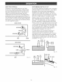
ELECTRmCAL
SAFETY
[] Doubme
insulated tools are
equipped with a
polarized plug (one Made is wider than the
other). This plug wHmfit in a polarized oufiet only
one way. If the plug does not fit fully in the
outlet, reverse the plug. [f it stHI does not fit,
contact a qualified electrician to install a polarized outlet. Do not change the plug in any way.
clothing, and gloves away from moving parts.
Loose clothes, jewelry, or long hair can be caught in
moving parts.
[] Avoid
before
on the
switch
accidental starting. Be sure switch is off
plugging in. Carrying tools with your finger
switch or plugging in tools that have the
on, invites accidents.
[] Remove adjusting keys or wrenches before
turning the tool on. A wrench or a key that is left
attached to a rotating part of the tool may result in
personal injury.
[] Do not overreach. Keep proper footing and
balance at ail fimes. Proper footing and balance
enables better control of the tool in unexpected
situations. Do not use on a ladder or unstable
support.
[] Use safety equipment. Always wear eye protection. Dust mask, nomskid safety shoes, hard hat,
or hearing protection must be used for appropriate
conditions.
TOOL
USE AND
CARE
[] Use clamps or other practical way to secure
and support the workpiece to a staMe platform.
Holding the work by hand or against your body is
unstable and may lead to loss of control.
Double insulation [] eliminates the need for the
threezwire grounded power cord and grounded
power supply system.
[] Do not force tool. Use the correct tool for your
application. The correct tool will do the job better
and safer at the rate for which it is designed.
[] Avoid body contact with grounded surfaces, such
as pipes, radiators, ranges, and refrigerators.
There is an increased risk of electric shock if your
body is grounded.
[] Do not use too[ if switch does not turn it on or
off. Any tool that cannot be controlled with the
switch is dangerous and must be repaired.
[] Don't expose power tools to rain or wet conditions. Water entering a power tool will increase the
risk of electric shock.
[] Do not abuse the cord. Never use the cord to carry
the tools or pull the plug from an outlet. Keep cord
away from heat, oH, sharp edges, or moving parts.
Replace damaged cords immediately. Damaged
cords increase the risk of electric shock.
[] When operating a power too[ outside, use an outdoor extension cord marked "W-A" or"W". These
cords are rated for outdoor use and reduce the risk of
electric shock.
PERSONAL
SAFETY
[] Stay alert, watch what you are doing and use
common sense when operating a power tool.
Do not use too[ while tired or under the influence of drugs, alcohol, or medication. A moment
of inattention while operating power tools may
result in serious personal injury.
[] Dress properly. Do not wear loose clothing
jewelry. Contain long hair. Keep your hair,
or
[] Disconnect the plug from power source before
making any adjustments,
changing accessoNes, or storing the tool. Such preventive safety
measures reduce the risk of starting the tool
accidentally.
[] Store idle tools out of the reach of children and
other untrained persons, q:oo[s are dangerous in
the hands of untrained users.
[] Maintain tools with care. Keep cutting too[s
sharp and cieam Properly maintained tools with
sharp cutting edges are less likely to bind and are
easier to control.
[] Check for misalignment or binding of moving
parts, breakage of parts, and any other condition that may affect the tool's operation. [f
damaged, have the tool serviced before using.
Many accidents are caused by poorly maintained
tools.
[] Use only accessories that are recommended by
the manufacturer for your mode[. Accessories
that may be suitable for one tool, may become
hazardous when used on another tool.
SERVICE
[] Toolservicemustbe performed
only by qualified repair personnel Service or maintenance
performed by unqualified personnel could result in
a risk of injury.
[] When servicing a tool, use only identical replacement parts. Follow instructions in the
Maintenance section of this manual. Use of
unauthorized parts or failure to follow Maintenance
instructions may create a risk of electric shock or
injury
Hold tool by insulated gripping surfaces when performing an operation where the cutting tool may
contact hidden wiring or its cord. Contact with a "live" wire will make exposed metal parts of the tool "live" and
shock the operator.
ADDITIONAL
RULES
FOR SAFE
OPERATION
[] Know your power tool. Read operator's manual
carefully. Learn its applications and limitations,
as well as the specific potential hazards related
to this tool. Following this rule will reduce the risk
of electdc shock, fire, or serious injury.
[] Always wear safety glasses. Everyday eyeglasses have only impact-resistant
lenses; they
are NOT safety glasses. Following this rule will
reduce the risk of serious personal injury.
[] Protect your lungs. Wear a face or dust mask if
the operation is dusty. Following this rule will
reduce the risk of serious personal injury.
[] Protect your hearing. Wear hearing protection
during extended periods of operation. Following
this rule will reduce the risk of serious personal
injury.
[] hspect tool cords periodically and, if damaged,
have repaired at your nearest authorized service center. Constantly stay aware of cord
location. Following this rule will reduce the risk of
electric shock or fire.
[] Make sure your extension cord is in good
condition. When using an extension cord, be
sure to use one heavy enough to carry the
current your product will draw. A wire gage size
(A.W.G.) of at least 16 is recommended for an
extension cord 100 feet or less in length. A cord
exceeding 100 feet is not recommended.
If in
doubt, use the next heavier gage. The smaller
the gage number, the heavier the cord. An
undersized cord wi[[ cause a drop in line voltage
resulting in ross of power and overheating.
[] Inspect for and remove atom
naris from lumber
before routing. Following this rule will reduce the
risk of serious personal injury
[] Drugs, a{cohol, medication. Do not operate tool
while under the influence of drugs, amcohol, or
any medication. Following this rule will reduce the
risk of electric shock, fire, or serious personal injury.
[] Save these instructions.
Refer to them frequent{y and use them to instruct others who
may use this tool If you loan someone this tool,
loan them these instructions also.
[] Check damaged parts. Before further use of the
tool, a guard or other part that is damaged
should be carefully checked to determine that it
will operate properly and perform its intended
function. Check for alignment of moving parts,
binding of moving parts, breakage of parts,
mounting, and any other conditions that may
affect its operation. A guard or other part that is
damaged should be properly repaired or replaced by an authorized service center. Following this rule will reduce the risk of shock, fire, or
serious injury
WARNING:
Some dust created by power
sanding, sawing, grinding, drilling, and other
construction activities contains chemicals known
to cause cancer, birth defects or other
reproductive harm. Some examples of these
chemicals are:
[] Do not abuse cord. Never carry the tool by the
cord or yank it to disconnect it from the receptacle. Keep cord away from heat, oil, and sharp
edges. Following this rule will reduce the risk of
electric shock or fire.
Your risk from these exposures varies,
depending on how often you do this type of work.
To reduce your exposure to these chemicals:
work in a well ventilated area, and work with
approved safety equipment, such as those dust
masks that are specially designed to filter out
microscopic particles.
• lead from lead-based paints,
• crystalline silica from bricks and cement and
other masonry products, and
• arsenic and chromium from chemically z
treated lumber.
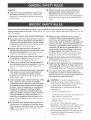
Important:Someofthefollowingsymbolsmaybeusedonyourtool.Pleasestudythemandlearntheirmeaning.
Properinterpretation
ofthesesymbolswill allowyoutooperatethetoolbetterandsafer.
SYMBOL
NAME
DESIG
NATIONIEXP
LANATION
V
Volts
Voltage
A
Amperes
Current
Hz
Hertz
Frequency
(cyclespersecond)
W
Watt
Power
Minutes
Time
'7..,
Alternating Current
Type or a characteristic of current
no
No Load Speed
Rotational speed, at no load
Class II Construction
Designates double-insulated
construction tools
min
_./min
Revolutions or Reciprocation
Per Minute
Revolutions, strokes, surface speed,
orbits etc. per minute
Safety Alert
indicates danger, warning or caution.
it means attention!!! Your safety is
involved.
Wet Conditions Alert
locations.
Do not expose to rain or use in damp
The purpose of safety symbols is to attract your attention to possible dangers. The safety symbols, and the
explanations with them, deserve your careful attention and understanding. The safety warnings do not by
themselves eliminate any danger. The instructions or warnings they give are not substitutes for proper accident
prevention measures.
SYMBOL
MEANING
DANGF R: Failure to obey a safety warning will result in serious injury to yourself or to others. Always
follow the safety precautions to reduce the risk of fire, electric shock and personal injury.
WARNING:
Failure to obey a safety warning can result in serious injury to yourself or to others.
Always follow the safety precautions to reduce the risk of fire, electric shock and personal injury.
yourself or to others.
CAUTRON:
Failure Always
to obey follow
a safety
the warning
safety precautions
may result toinreduce
property
thedamage
risk of fire,
or electric
personalshock
injuryand
to
personal injury.
NOTE:
Advises you of information or instructions vital to the operation or maintenance of the equipment.
SAVE THESE INSTRUCTIONS
Depth of Cut
Collet
Horsepower
input
0 = 1=1/2 in.
1/2 in. and 1/4 in.
2
No Load Speed
Power Cord
Net Weight
15,000 =25,000/min
10 ft.
8 Ibs. 5 oz.
120 volts, 60 Hz, AC only, 9.5 amps
Your router has been shipped completely assembled.
inspect it carefully to make sure no breakage or
damage has occurred during shipping. If any parts are
damaged or missing, contact your nearest Sears
Retail Store to obtain replacement parts before
attempting to operate router. A wrench, a 1/'4 in. collet
assembly, and this operator's manual are also
included.
_
WARMNG:
If any parts are missing, do not
operate this tool until the missing parts are
replaced. Failure to do so could result in possible
serious personal injury.
DOUBLEmNSULATION
Doubleinsulationisa conceptin safetyinelectric
powertools,whicheliminates
theneedfortheusual
three-wire
groundedpowercord.Allexposedmetal
partsareisolatedfromtheinternalmetalmotor
components
withprotectinginsulation.Double
insulatedtoolsdo notneedto begrounded.
Important:Servicingofa toolwithdoubleinsulation
requiresextremecareandknowledge
ofthesystem
andshouldbeperformedonlybya qualifiedservice
technician.
Forservice,wesuggestyoureturnthetool
toyournearestauthorized
servicecenterfor repair.
Alwaysuseoriginalfactoryreplacement
partswhen
servicing.
,t_
VVARNING: The double insulated system is
intended to protect the user from shock resulting
from a break in the tool's internal wiring. Observe
all normal safety precautions to avoid electrical
shock.
ELECTRICAL
CONNECTRON
Your router has a precision built electric motor, it
should be connected to a power suppmy that is 120
volts, 60 Hz, AC only (normal household current).
Do not operate this tool on direct current (DC). A
substantial voltage drop will cause a loss of power
and the motor will overheat, if your tool does not
operate when plugged into an outlet, double-check
the power supply.
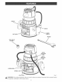
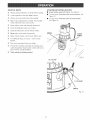
SWITCH
To turn the router ON, toggle the switch to the I
position. To turn the router OFF, toggle the switch to
the O position.
SPmNDLE LOCK
The spindle lock secures the spindle while you make
adjustments and acts as a retainer to keep the router
body from coming out of the base.
DEPTH
ADJUSTING
RING
The depth adjusting ring allows you to adjust the
depth of cut.
LOCKING
ARM
The locking arm secures the motor housing in the
base.
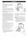
CHIP SHIELD
A clear plastic chip shield is installed on the front of
your router for protection against flying dust and
chips. The shield is designed to fit the opening of the
router base. if necessary to remove chip shield,
squeeze the tabs on each end and pull outward. To
replace, squeeze the tabs at each end, fit into
opening, then release. For your protection, do not
use router without chip shield properly in place.
Peel the horsepower label from chip shield and
discard.
VARIABLE
SPEED
Your router has advanced electronic features,
designed to assist you in getting the maximum use
from your router. By making proper speed selections,
your router can be adjusted to specific routing needs.
This eliminates much of the guess work previously
needed to perform a given job. Both the experienced
and inexperienced router users benefit, obtaining
professional like results with fewer job errors.
The variable speed control allows the router speed to
be adjusted from 15,000 to 25,000 RPM. The
variable speed control selector is conveniently located
on the top of the motor housing.
Speed can be set according to the approximate cutter
diameter you will be using and to the hardness of the
material being cut. The best cuts are made when the
cutter is fed through material at the proper rate of
feed.
VACUUM
ATTACHMENT
The vacuum attachment allows you to attach a
standard shop vacuum to the router for easy clean up.
HANDLE
CHIP
SHIELD
POWER
HANDLE
1/4in.COLLET
ASSEMBLY
DEPTH
ADJUSTING
LOCKING ARM
SPINDLE LOCK
COLLETNUT
_
Fig. 1
WARNING:
Do not allow familiarity with your router to make you careless. Remember that a careless fraction
of a second is sufficient to inflict severe injury.
8
_
WARNmNG:
Yourroutershouldneverbe
connectedtopowersupplywhenyouare
assemblingparts,makingadjustments,
installing
or removingcutters,cleaning,orwhennotin
use.Disconnecting
routerwill preventaccidental
startingthatcouldcauseseriouspersonalinjury.
[] Lay router down on table to gain easy access to
collet nut.
[] Place wrench provided onto collet nut and turn
couterclockwise to loosen.
_lL
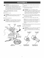
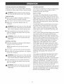
mNSTALLING/REMOVING
CUTTERS
See Figure 2.
[] Unplug your router.
_
WARNING:
Failure to unplug your router could
result in accidental starting causing serious
injury.
[] Depress spindle lock.
_
[]
To install cutter: Insert shank of cutter into coliet.
The shank of the cutter should be close to but not
touching bottom of collet.
[]
To remove cutter: Remove cutter from collet.
NOTE: The 1/2 in. collet is machined to precision
tolerances to fit cutters with 1/2 in. diameter
shanks. The 1/4 in. collet is machined to precision
tolerances to fit cutters with 1/4 in. diameter
shanks.
WARNING:
To prevent damage to the spindle
or spindle lock, always allow motor to come to a
complete stop before engaging spindle lock.
CUTTER
COLLET
NUT
TO LOOSEN
COLLETNUT
WARNmNG: If you are changing a cutter
immediately after use, be careful not to touch the
cutter or coilet with your hands or fingers. They
will get burned because of the heat buildup from
cutting. Always use the wrench provided.
[] Tighten the collet nut securely by turning clockwise
with wrench provided.
[] Release spindle lock.
WRENCH
_
WARNING:
Do not use cutters with undersized
shanks. Undersized shanks will not tighten
properly and could be thrown from tool causing
injury.
1/4 in. COLLET
ASSEMBLY
DEPRESS
SPtNDLELOCK
Fig. 2
CNTTERWJTN1/4 in.
SHANKDIAMETER
1/2in. COLLET
ASSEMBLY
CNTTERWJTN1/2 in.
SHANKDIAMETER
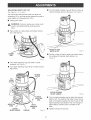
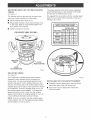
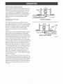
ADJUSTmNG
DEPTHOF CUT
[] Turn the depth indicator ring until the zero lines up
with the indicator point on the base. See Figure 5.
See Figures 3, 4, 5, and 6
We recommend that cuts be made at a depth not
exceeding 1/8 in. and that several passes be made to
reach depths of cut greater than 1/8 in.
[] Unplug your router.
,_
WARNING:
Failure to unplug your router could
result in accidental starting causing serious
injury.
[] Place router on a flat surface and loosen locking
arm. See Figure 3.
CUTTERAT ZERO
DEPTHOF CUT
LOCKING
ARM
LOOSEN
Fig, 5
[] Position router so that the cutter can extend below
the subbase for desired depth setting. See
Figure 6.
Fig. 3
[] Turn depth adjusting ring until cutter is inside
subbase. See Figure 4.
[] Turn depth adjusting ring until tip of cutter touches
flat surface.
TO RAISE
CUTTER
TO
LOWER
CUTTER
\
CUTTEREXTENDED
BELOW SUBBASE
DEPTH
ADJUSTING
RiNG
INDICATOR
POINT
CUTTER
INSIDE SUBBASE
[] Turn the depth adjusting ring to obtain the desired
depth of cut. The distance the cutter moves can be
read on the depth adjusting ring. Each mark on the
depth adjusting ring indicates 1/32 inch change in
depth setting, indicator point is located on the
base.
DEPTH
INDICATOR
RiNG
SUBBASE
Fig. 6
[] Tighten locking arm securely.
Fig. 4
10
ADJUSTRNG
DEPTHOF CUT (WroTH
ROUTER
SeeFigure
The speed selection chart shown gives suggested
speed settings based on the diameter of the cutter
and the type of material being routed.
7
We suggest that you practice with the variable speed
feature of your router before installing a cutter and
making cuts in wood.
The indicator point on the base can be used when
using your router mounted to a router table.
[] Set the cutter at zero depth of cut.
[] Rotate depth indicator ring to desired depth of cut
on the scale. Refer to "ADJUSTING DEPTH OF
CUT" earlier in this manual.
SPEED SELECTION CHART
CUTTER SmZE
[] Tighten locking arm securely.
MATERIAL
1/4
3/8
1/2
3/4
SOFT
E-F
D-E
A-B
A
MEDmUIV] D-E
C-D
A
A
B-C
A
A
C-D
B-C
FOR ROUTER TABLE USE ONLY
HARD
VERY HARD
C-D
D-E C-D
iNDiCATOR
POINT
DEPTH
ADJUSTMENTRJNG
Fig. 7
ADJUSTING
SPEED
See Figure 8.
Your router has a variable speed control selector
designed to allow operator control of speed and
torque limits. You can make speed selections best
suited to the type of cut, the material being cut, and
the size of bit being used. The variable speed control
selector allows you to adjust router speed from 15,000
to 25,000 RPM. There is a six=step scale (A to F) on
the variable speed control selector. To increase the
speed and torque of your router, turn the variable
speed control selector to a higher setting (F). Turn to
a lower setting to decrease speed and torque.
Fig. 8
mNSTALUNG
THE VACUUM
ATTACHMENT
[] Place the vacuum attachment in the area at the
rear of the router under the locking arm.
[] Secure the vacuum attachment with the two
screws provided.
NOTE: If you do not want to use the variable speed
control selector, turn it to the highest possible setting,
and the feature will not be active.
11
HELPFUL
HNTS
STARTING/STOPPING
J"
AHways champ workpiece
J
A safe operator is one who thinks ahead.
_/
AHways wear eye protection when routing.
_/
Make setup adjustments carefully. Then douMe
check, Measure twice and cut once.
J
Keep cutters dean and property sharpened.
ROUTER
[] Grasp handles using both hands. See Figure 9
secureHy before routing.
[]
To start router: Press the switch to the I position. See
Figure 10.
[]
To stop router: Press the switch to the 0 position.
See Figure 10.
Don't Hetfamiliarity make you careHess.
J"
Study aH safety tulles and do thejob
safeHy.
J
Never pHaceyour hands injeopardy.
_/
Make certain champs can't Hoosen whiHe in use.
_/
Test difficuHt setups on scrap -- Don't waste
Humber.
J
Man each operation before you begin.
J"
Provide for smoother operation by cleaning your
HANDLE
/
router frequentHy. Shake router or Mow with an air
jet to remove sawdust buildup.
Think safety by thinking
POWER
HANDLE
/
ahead.
( 0 } TO STOP
( I ) TO START
SWITCH
Fig. 10
12
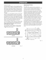
PLACINGROUTERONVVORKPIECE
Placingyourrouteron a workpiece
differs,depending
onthetypeofrouting:edgeroutingor internalrouting.
_
WARNING:Remainalertandwatchwhatyou
aredoing.Do not operaterouterwhenfatigued.
The best rate of feed is one that does not slow down
the router motor more than one-third of its no-load
speed. If the router is fed too fast, it will take large
chips out of the wood and leave gouge marks. If the
router is fed too slow, it will scorch or burn the wood.
WARMNG:
Keep a firm grip on router with both
hands at all times. Failure to do so could result in
[] Upon completion of cut, turn motor off and let it
come to a complete stop before removing router
from work surface.
Feeding Too Fast
Clean, smooth routing and edge shaping can be done
only when the bit is revolving at a relatively high
speed and is taking very small bites to produce tiny,
cleanly severed chips. If your router is forced to move
forward too fast, the RPM of the bit becomes slower
than normal in relation to its forward movement. As a
result, the bit must take bigger bites as it revolves.
"Bigger bites" mean bigger chips, and a rougher
finish. Bigger chips also require more power, which
could result in the router motor becoming overloaded.
WARNING:
Never pull router out of work and
place upside down on work surface before the
cutter stops.
INTERNAL
ROUTING
[] Tilt router and place on workpiece, letting edge of
subbase contact workpiece first.
Under extreme force-feeding conditions the relative
RPM of the bit can become so slow--and the bites it
has to take so large -- that chips will be partially
knocked off (rather than fully cut off), resulting in
splintering and gouging of the workpiece. See
Figure 11.
NOTE: Be careful not to let router bit contact
workpiece.
[] Turn router on and let motor build to its full speed.
[] Feed cutter into workpiece gradually until subbase
is level with workpiece.
,_
Your router is an extremely high-speed tool (15,000 25,000 RPM no-load speed), and will make clean,
smooth cuts if allowed to run freely without the
overload of a forced (too fast) feed. Three things that
cause "force feeding" are bit size, depth-of-cut, and
workpiece characteristics. The larger the bit or the
deeper the cut, the more slowly the router should be
advanced. If the wood is very hard, knotty, gummy or
damp, the operation must be slowed still more.
WARMNG:
Keep a firm grip on router with both
hands at all times. Failure to do so could result in
loss of control leading to possible serious injury.
[] Upon completion of cut, turn motor off and let it
come to a complete stop before removing router
from work surface.
_
The "secret" of professional routing and edge shaping
lies in making a careful set-up for the cut and in
selecting the proper rate of feed.
The proper rate of feed depends on several factors:
the hardness and moisture content of the wood, the
depth of cut, and the cutting diameter of the bit. When
cutting shallow grooves in soft woods such as pine, a
faster rate of feed can be used. When making deep
cuts in hardwoods such as oak, a slower rate of feed
should be used.
loss of control leading to possible serious injury.
,_
ROUTER
RATE OF FEED
EDGEROUTING
[] Placerouteronedgeofworkpiece,makingsure
therouterbitdoesnotcontactworkpiece.
[] Turnrouteronandlet motorbuildto itsfullspeed.
[] Beginyourcut,graduallyfeedingcutterinto
workpiece.
,_
FEEDING
WARMNG:
Never pull router out of work and
place upside down on work surface before the
cutter stops.
You can always detect "force feeding" by the sound of
the motor. Its high-pitched whine will sound lower and
stronger as it loses speed. Also, the strain of holding
the tool will be noticeably increased.
13
D_RECTION (EXTERNAL}
See Figure 72.
Feeding Too Slow
it is also possible to spoil a cut by moving the router
forward too slowly. When it is advanced into the work
too slowly, a revolving bit does not dig into new wood
fast enough to take a bite; instead, it simply scrapes
away sawdust:like particles. Scraping produces heat,
which can glaze, burn, or mar the cut and in extreme
cases, can even overheat the bit so as to destroy its
hardness.
The router motor and bit revolve in a clockwise
direction. This gives the tool a slight tendency to twist
(in your hands) in a counterclockwise direction,
especially when the motor revs up (as at starting).
Because of the extremely high speed of bit rotation
during a "proper feeding" operation, there is very little
kickback to contend with under normal conditions.
However, should the bit strike a knot, hard grain,
foreign object, etc. that would affect the normal
progress of the cutting action, there will be a slight
kickback--sufficient
to spoil the trueness of your cut if
you are not prepared. Such a kickback is always in
the direction opposite to the direction of bit rotation.
in addition, it is more difficult to control a router when
the bit is scraping instead of cutting. With practically
no load on the motor the bit will be revolving at close
to top RPM, and will have a much greater than normal
tendency to bounce off the sides of the cut (especially
if the wood has a pronounced grain with hard and soft
areas). As a result, the cut produced may have
rippled, instead of straight sides. See Figure 7 7.
To guard against such a kickback, plan your setup
and direction of feed so that you will always be
thrusting the tool--to hold it against whatever you are
using to guide the cut--in the same direction that the
leading edge of the bit is moving. In short, the thrust
should be in a direction that keeps the sharp edges of
the bit continuously biting straight into new (uncut)
wood.
"Too:slow feeding" can also cause your router to take
off in a wrong direction from the intended line of cut.
Always grasp and hold your router firmly w{th
both hands when routing.
You can detect "too:slow feeding" by the runaway,
high:pitched sound of the motor; or by feeling the
"wiggle" of the bit in the cut.
3TPROPER CUTTmNGSEQUENCE
4
TOOFAST
1/4 in. to I in.
Fig. 12
TOOSLOW
Fig. 11
14
DIRECTION
(iNTERNAL)
Wheneveryouareroutinga groove,yourtravel
shouldbeina directionthatplaceswhateverguide
youareusingat theright=hand
side.inshort,when
theguideis positioned
as shownin thefirstpartof
Figure13,tooltravelshouldbeleftto rightand
counterclockwise
aroundcurves.Whentheguideis
positionedasshowninthesecondpartof Figure13,
tooltravelshouldberighttoleftandclockwisearound
curves.If thereis a choice,thefirstsetupis generally
theeasiesttouse.ineithercase,thesidewaysthrust
youuseis againsttheguide.
GUIDE
OUTSIDE
ROTATION
I
DEPTH
OF CUT
As previously mentioned, the depth of cut is important
because it affects the rate of feed that, in turn, affects
the quality of the cut (and, also, the possibility of
damage to your router motor and bit). A deep cut
requires a slower feed than a shallow one, and a too
deep cut will cause you to slow the feed so much that
the bit is no longer cutting, it is scraping, instead.
Making a deep cut is never advisable. The smaller
bitsespecially those only 1/16 inch (1.6 mm)in
diameter -- are easily broken off when subjected to
too much side thrust. A large enough bit may not be
broken, but if the cut is too deep a rough cut will result
-- and it may be very difficult to guide and control the
bit as desired. For these reasons, we recommend that
you do not exceed 1/8 in. depth of cut in a single
pass, regardless of the bit size or the softness or
condition of the workpiece. See Figure 14.
To make deeper cuts it is therefore necessary to
make as many successive passes as required,
lowering the bit 1/8 in. for each new pass. In order to
save time, do all the cutting necessary at one depth
setting, before lowering the bit for the next pass. This
will also assure a uniform depth when the final pass is
completed. See Figure 15.
THRUST
ROTATION
FEED
DETERMINING
GUIDE
DEPTH
OF CUT
WIDTH
OF CUT
GUIDE INSIDE
ROTATION _
GUIDE _
_
THRUST
Fig. 14
ROTATION _
FEED
2ND. PASS
/
2ND.
PASS
Fig. 1 3
1ST.
r_ PASS
m m
m
Fig. 1 5
15
ROUTRNG
Yourrouteris a versatiletoolandcanbeusedfor
manydifferentapplications.
Youmayroutgrooves,
carvedesignsusinga template,carvedesignsby
freehand,tapertameandchairlegs,mortisedoor
jambs,or createjoints.
ROUTING
GROOVES
SeeFigure 16
\
When routing across the face of boards, set router at
desired depth of cut, place the edge of router base
against workpiece, and turn on the router. Slowly feed
the cutter into the workpiece along desired line of cut.
_
WARNmNG: If desired depth of cut is greater
than can be safely cut in one pass, make cuts in
two or more passes.
Fig. 16
When routing straight cuts across stock, clamp a
straight edge to the workpiece to use as a guide.
Position the straightedge parallel to the line of cut and
offset the distance between the cutting edge of the
cutter and the edge of the router base. Hold the router
base against the straightedge and rout the groove.
[] Rout the pattern in two or more passes. Make the
first pass at 25% of the desired depth of cut. This
wiJJprovide better control as well as being a guide
for the next pass.
NOTE: Do not rout deeper than 1/8 in. per pass.
When routing a groove wider than the diameter of the
cutter, clamp a straightedge on both sides of the
cutJines. Position both guides parallel to the desired
line of cut and spaced equal distances from the
desired edges of the groove. Rout along one guide;
then, reverse direction and rout along the other guide.
Clean out any remaining waste in the center of the
groove freehand.
,_
ROUTING BY FREEHAND
WARMNG:
Do not use large router bits for
freehand routing. Use of large router bits when
freehand routing could cause loss of control or
create other hazardous conditions that could
cause possible serious personal injury. When
using a router tame, large router bits should be
used for edging only. Do not use router bits that
are larger in diameter than the opening in router
base for any purpose.
See Figure 17
When used freehand, your router becomes a flexible
and versatile took This flexibility makes it possible to
easily rout signs, relief sculptures, etc.
There are two basic techniques for freehand routing:
[] Routing letters, grooves, and patterns into wood.
[] Routing out the background, leaving the letters or
pattern raised above the surface.
When freehand routing, we suggest the following:
[] Draw or layout the pattern on workpiece.
[] Choose the appropriate cutter.
NOTE: A core box or V-groove bit is often used for
routing letters and engraving objects. Straight bits
and bah mills are often used to make relief
carvings. Veining bits are used to carve small,
intricate details.
I
Fig. 17
16
ROUTING
WiTHGUIDEBUSHINGS
WhenusingtheTemplateGuideBushingsitemNo.925082with},ourrouter,youmustvisuallycenterthe
bitwiththebushingbeforebeginning
yourcut.Your
routersubbasemaybeadjustedby loosening
the
screwsholdingthesubbasetoyourrouter.Besureto
tightenlockingarmbeforecenteringbit in bushing.
Aftercenteringbitwithbushing,tightenscrews
securely.
EDGINGWITHPILOTBITS
SeeFigure 18
TOP EDGESHAPING
Arbor-type bits with pilots are excellent for quick,
easy, edge shaping. They will follow workpiece edges
that are either straight or curved. The pilot prevents
the bit from making too deep a cut; and holding the
pilot firmly in contact with the workpiece edge
throughout prevents the cut from becoming too
shallow.
GUIDE
WORK
Whenever the workpiece thickness together with the
desired depth of cut (as adjusted by router depth
setting) are such that only the top part of the edge is
to be shaped (leaving at least a 1/16 inch thick uncut
portion at bottom), the pilot can ride against the uncut
portion, which will serve to guide it. See Figure 18.
However, if the workpiece is too thin or the bit set too
low so that there will be no uncut edge to ride the pilot
against, an extra board to act as a guide must be
placed under the workpiece. This "guide" board must
have exactly the same contour -- straight or curved
-- as the workpiece edge. if it is positioned so that its
edge is flush with the workpiece edge, the bit will
make a full cut (in as far as the bit radius). On the
other hand, if the guide is positioned as shown in
Figure 18 (out from the workpiece edge), the bit will
make less than a full cut -- which will alter the shape
of the finished edge.
PILOT
WHOLE EDGE SHAPING
Fig. 18
NOTE: Any of the piloted bits can be used without a
pilot for edge shaping with guides, as preceding. The
size (diameter) of the pilot that is used determines the
maximum cut width that can be made with the pilot
against the workpiece edge - the small pilot exposes
all of the bit; the large one reduces this amount by
1/16 inch.
17
_j
WARNING:Whenservicing,useonlyidentical
Craftsmanreplacement
parts.Useofanyother
partmaycreatea hazardor causeproduct
damage.
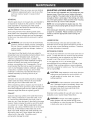
GENERAL
Onlythe partsshownonthepartslist,areintendedto
berepairedor replacedby thecustomer.Allother
partsrepresentan importantpartofthedouble
insulationsystemandshouldbeservicedonlybya
qualifiedSearsservicetechnician.
Avoidusingsolventswhencleaningplasticparts.
Mostplasticsaresusceptible
todamagefromvarious
typesofcommercial
solventsandmaybedamaged
bytheiruse.Usecleanclothstoremovedirt,carbon
dust,etc.
_l_ WARNING:Donotat anytimeletbrakefluids,
gasoline,petroleum:based
products,penetrating
oils,etc.comein contactwithplasticparts.They
containchemicals
thatcandamage,weakenor
destroyplastic.
it hasbeenfoundthatelectrictoolsaresubjectto
accelerated
wearandpossibleprematurefailurewhen
theyareusedonfiberglassboats,sportscars,
wallboard,spacklingcompounds,
or plaster.The
chipsandgrindingsfromthesematerialsarehighly
abrasivetoelectrictoolpartssuchas bearings,
brushes,commutators,
etc.Consequently,
it is not
recommended
thatthistoolbeusedforextended
workonanyfiberglassmaterial,
wallboard,spackling
compounds,
or piaster.Duringanyuseonthese
materialsit is extremely
importantthatthetoolis
cleanedfrequentlyby blowingwithanairjet.
CUTTERS
Getfastermoreaccuratecuttingresultsbykeeping
cutterscleanandsharp.Removeallaccumulated
pitchandgumfromcuttersaftereachuse.
Whensharpening
cutters,sharpenonlytheinsideof
thecuttingedge.Nevergrindtheoutsidediameter.Be
surewhensharpening
theendof a cutterto grindthe
clearance
anglethesameas originallyground.
COLLET
Dustandchipsmaycollectonthecoiletfromtimeto
time,makingit necessarytocleanthecollet.Todo
so,removethecolletassemblyandwipeitwitha
cleandryrag.Cleanthetaperin theshaftinthesame
manner.Neverimmersethecolletor endoftheshaft
in a solventor inwater.Beforereplacingthecollet
assembly,
puta dropof SAE30motoroilonthe inside
ofthenut,onthethreadsoftheshaft,andonthe
taperintheshaft.Replacethecolletassemblyonto
theshaftbyhandonly.Nevertightenthe coJletnut
withouta bit inthe collet.Thisactioncould
permanently
damagethecollet.
18
ADJUSTING
LOCKING
ARM TENSION
Over time and with repeated use, the locking arm may
become loose. When this occurs, tighten the elastic
stop nut slightly. The elastic stop nut should be loose
enough so there is some play in the locking arm when
it is in the open position. Make sure the motor housing
does not move up or down when clamped.
NOTE: Do not over tighten the elastic stop nut. The
locking arm should clamp tightly to secure the motor
housing.
If the locking arm becomes worn beyond adjustment,
a repair kit is available. Please contact your service
center to order the appropriate router locking arm
repair kit.
LUBRICATRON
All of the bearings in this tool are lubricated with a
sufficient amount of high grade lubricant for the life of
the unit under normal operating conditions. Therefore,
no further lubrication is required.
EXTENSmON
CORDS
The use of any extension cord will cause some Joss of
power. To keep the loss to a minimum and to prevent
tool overheating, use an extension cord that is heavy
enough to carry the current the tool will draw.
A wire gage size (A.W.G.) of at least 14 is
recommended for an extension cord 100 feet or Jess
in length. When working outdoors, use an extension
cord that is suitable for outdoor use. The cord's jacket
will be marked WA.
_jl_ CAUTmON: Keep extension cords away from the
cutting area and position the cord so that it will
not get caught on lumber, tools, etc, during
cutting operation.
_
WARNING:
Check extension cords before each
use. Jf damaged replace immediately. Never use
tool with a damaged cord since touching the
damaged area could cause electrical shock
resulting in serious injury.
Extension cords suitable for use with your router are
available at your nearest Sears Retail Store.
_
WARMNG:
Always wear safety goggles or
safety glasses with side shields during power
tool operation or when blowing dust. If operation
is dusty, also wear a dust mask.
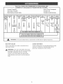
THE FOLLOWING
RECOMMENDED
ACCESSORIES
ARE
CURRENTLY
AVAmLABLE AT SEARS RETAmL STORES.
Dovetail
Template
Rout-A-Form
Pantograph
Butt Hinge Template
Template
Bet
MultFPurpose
Template
Guide Bushing
COMBF VEINING
NATION BIT
PANEL
CUTTER
Router Guide
CORE
BOX
BIT
STRAIGHT COMBF
HINGE DOVETA& RABBET OGEE,
COVE
BEAD
ARBOR
FACE
NATION MORTISIN(_ CUTTER
BIT
ROMAN0
QUARTER- WITH BALL
BIT,
BIT
STRAIGHT
BIT
BITS
45°
ROUND BEARINGS
BEVEL
CHAMFER
BIT
2589
CUTTER
BIT
[Z[]
?
VoGROOVE
CHAMFER
WITH 2
BALL
BEARINGS
(1/2 in. &
5/8 in,)
_25895
I _ FOR CARBIDETIPPEDEDGEFORMINGBITS I
m
[_ 2589
25895
FOR
FOR
HIGH
CARBIDETIPPED
SPEEDSTEELEDGEFORMINGBITS
EDGEFORMINGBITS I
WARNING:
ROUTER
The use of attachments or accessories
TABLES
GUIDE
With a router table your router is converted into a
high:speed shaper.
,_
not listed above might be hazardous.
BUSHINGS
Guide bushings allow for accurate guiding of router
along any workpiece or template edge and for
grooving or shaping of curved contours.
WARNmNG: Only use router tables with proper
guarding for the cutter and with "on board" switch
controlled receptacles (Part No. 9:25188).
Failure to use router tables with appropriate
safety features could result in serious personal
injury.
19
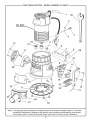
_-
CRAFTSMAN
ROUTER
- MODEL
NUMBER
315.269211
25
SEE NOTE
3
12
22
5
7
8
/
28
10
/
20
13
NOTE: The assembly shown represents an important part of the double insulated system. To avoid the
possibility of alteration or damage to the system, service should be performed by your nearest
Sears repair center. Contact your nearest Sears retail store for service center information.
20
•
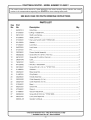
CRAFTSMAN
ROUTER
- MODEL
NUMBER
315.269211
.
J
The
number
model
in allnumber
correspondence
will be found
regarding
on a plate
your attached
ROUTER toor the
when
motor
ordering
housing.
repairAlways
parts. mention the model 1
SEE BACK PAGE FOR PARTS ORDERING
INSTRUCTIONS
PARTS LIST
Key
Part
No.
No.
Description
1
940301014
Data Plate ....................................................................................................
1
2
671245001
E-Ring **STD581018 ...................................................................................
1
3
690141001
Shaft Lock Spring ........................................................................................
1
4
671249001
Shaft Lock Pin .............................................................................................
1
5
671243001
Hex Lock Nut (#1/4-20) **STD541425 .........................................................
1
6
631123001
Washer .........................................................................................................
1
7
671260001
Lock Stud ....................................................................................................
1
8
640676001
Lock Lever ...................................................................................................
1
9
671247001
Pin ...............................................................................................................
1
10
200236001
Power Handle Assembly .............................................................................
1
11
660062005
Screw (#10-24 x 9/16 in. Pan Hd.) ..............................................................
2
12
660161001
Screw (#8-10 x 5/8 in. Pan Hd.) ..................................................................
4
13
290061048
Lead .............................................................................................................
1
14
760357001
Switch ..........................................................................................................
1
15
870126002
Wire Nut **STD375004 ................................................................................
2
16
660136001
Screw (#10-32 x 1/4 in.) **STD511102 ........................................................
3
17
511983001
Subbase ......................................................................................................
1
18
200234001
Base Assembly ............................................................................................
1
19
511987001
Chip Shield ..................................................................................................
1
20
200235001
Handle Assembly .........................................................................................
1
21
300618002
Collet Assembly (1/4 in.) ..............................................................................
1
22
300627004
Collet Assembly (1/2 in.) ..............................................................................
1
23
512546001
Bezel ............................................................................................................
1
24
900515001
Switch Felt ...................................................................................................
1
25
670346001
Wrench ........................................................................................................
1
26
511989001
Vacuum Attachment
1
27
660284004
Screw (#6-32 X 3/8 in.) **STD510603 ..........................................................
2
28
000727001
Lock Lever Repair Kit ..................................................................................
1
983000-431
Operator's
1
Qty.
....................................................................................
Manual .......................................................................................
* Standard Hardware Item - May Be Purchased Locally
** Available from Div. 98 - Source 980.00
21
Your Home
For repair-in
your home-of
all major brand appliances,
lawn and garden equipment, or heating and cooling systems,
no matter who made it, no matter who sold it!
..................
For the replacement parts, accessories and
owner's manuals that you need to do-it-yourself.
..................
For Sears professional installation of home appliances
and items like garage door openers and water heaters.
..................
1-8 00-4-MY-H 0 ME® (1-800-469-4663)
oa,,
an t, o, o,oht sod
Oaoada
www.sears.com
..........
www.sears.ca
Our
Home
For repair of carry-in items like vacuums, lawn equipment,
and electronics, call or go on-line for the location of your nearest
Sears Parts & Repair Center.
1-800-488-1222
Call anytime,
day or night (U.S.A. only)
www.sears.com
To purchase a protection agreement (U.S.A.)
or maintenance agreement (Canada) on a product serviced
1-800-827-6655
Pard pedir servicio
(U.S.A.)
1-800-361-6665
de reparacien
Au Canada
a domicilio, y para ordenar piezas.
1-8 8 8-S U- HO G AR sM
by Sears:
(Canada)
pour service en frangais:
1 -800- LE- FO YER Mc
(1-800-533-6937)
(1-888-784-6427)
www.sears.ca
...............
..............
SEARS
® Registered
Trademark
/ TMTrademark
/
SM
Service
Mark of Sears,
Roebuck
® Marca Registrada
/ TM Marca de F_brica / SM Marca de Servicio
de Sears,
MC
Marque
de commerce
/ MD Marque
d6pos6e
de Sears,
Roebuck
and Co.
and Co.
Roebuck
and
Co.
® Sears,
Roebuck
and Co.