1
APPENDIX -A
When the GSM-DL2 is connected with a car alarm,
1). Connect the “Start Disable” wire of the car alarm to the “ARM” input of GSM-DL2
Note:
A). For those car alarms, whose “Start Disable” is 0V when it is armed, put the Jumper JP2
of the GSM-DL2 at PIN 1 & PIN 2 position (shorted).
B). For those car alarms, whose “Start Disable” is +12V when it is armed, put the Jumper
JP2 of the GSM-DL2 at PIN 2 & PIN 3 position (shorted).
2). Connect the “Siren Output” wire of the car alarm to the “ZH” of the GSM-DL2.
Note: The “Siren Output” must be +12V, and continuous ON minimum 2 seconds, when it’s
activated.
3). Connects +12V power of the car’s battery (through a protection fuse) to supply the GSM-DL2.
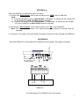
APPENDIX-B
When the GSM-DL2 is connected with LS-9001A security system, the wiring is as below.
SELECT THE ALARM
OUT TERMINALS AS
+12VDC OUTPUT
ARM
ZH
GND
+12V
GSM-DL2
* Put the jumper JP2 of GSM-DL2 at 2 & 3 position.
6