1
UV/VIS Detector
UVD 170S/340S
Operating Instructions
Version:
3.01
Date:
July 14, 2000
© Dionex Softron 2000
Doc.: UVD170SUVD340_OI_E_V301.doc
Declaration of Conformity
Product:
Type:
UV/VIS Detector
UVD 170S/340S
Dionex Softron GmbH herewith declares conformity of the above products with the
respective requirements of the following regulations:
•
EN 50081-1 : 1992:
Electromagnetic Compatibility (EMC) - Generic emissions standard
Part 1: Residential, commercial and light industry
•
EN 50082-1 : 1992:
Electromagnetic Compatibility (EMC) - Generic immunity standard
Part 1: Residential, commercial and light industry
•
EN 61000-3-2 : 1998
Electromagnetic Compatibility (EMC)
Part 3 / Section 2: Limits for harmonic current emissions
This declaration is issued for the manufacturer
Dionex Softron GmbH
Dornierstrasse 4
D-82110 Germering
by the President, Dr. Peter Jochum.
January 16, 2001
Operating Instructions UVD 170S/340S
Contents
1
Introduction........................................................................................................................ 1
1.1 Unpacking ..................................................................................................................... 1
1.2 Warranty........................................................................................................................ 1
1.3 How to Use This Manual .............................................................................................. 1
1.4 Intended Use of This Instrument ................................................................................... 2
2
Installation.......................................................................................................................... 3
2.1 Positioning and Environment ........................................................................................ 3
2.2 Mains Connection ......................................................................................................... 3
2.2.1 Fuse Replacement................................................................................................... 4
2.3 Fluidic Connections....................................................................................................... 5
2.4 Rear Panel Connections ................................................................................................ 5
2.5 Installation on the PC-Interface Board .......................................................................... 6
3
Overview ............................................................................................................................. 7
3.1 Principle of Operation ................................................................................................... 7
4
Operation ............................................................................................................................ 8
4.1 Switching the Unit On/Off ............................................................................................ 8
4.2 Status LED on the Front Panel ...................................................................................... 8
4.3 Installation and Operation within CHROMELEONTM .................................................. 9
4.3.1 Communication Port............................................................................................... 9
4.3.2 Required CHROMELEONTM Modules .................................................................. 9
4.3.3 Installation with the CHROMELEONTM Installation Tool..................................... 9
4.3.4 Operation within CHROMELEONTM ................................................................... 11
4.3.5 Spectra Calibration under CHROMELEONTM ..................................................... 12
5
Troubleshooting ............................................................................................................... 13
6
Maintenance ..................................................................................................................... 15
6.1 General Information .................................................................................................... 15
6.2 Lamp............................................................................................................................ 17
6.2.1 Lamp Removal...................................................................................................... 17
6.2.2 Lamp Replacement ............................................................................................... 17
6.3 Flow Cell ..................................................................................................................... 18
6.3.1 Flow Cell Versions ............................................................................................... 18
6.3.2 Flow Cell Removal............................................................................................... 21
6.3.3 Flow Cell Replacement ........................................................................................ 21
6.3.4 Flow Cell Cleaning............................................................................................... 21
7
Technical Specifications .................................................................................................. 23
8
Accessories and Spare Parts ........................................................................................... 24
8.1 Standard Accessories, UVD 170S/340S ..................................................................... 24
8.2 Spare Parts................................................................................................................... 24
i
Operating Instructions UVD 170S/340S
1 Introduction
1.1 Unpacking
To unpack the unit, proceed as follows:
• Place the box on the floor and remove the accessories pack.
• Pull out the unit, slowly and carefully, using the two foam inserts.
• Remove the polythene packaging by placing the unit on a firm base and lifting at one side,
then the other, while drawing the packaging out from underneath it.
Please note:
Retain all original packing materials in a safe place. It is the optimum
packaging for shipping the unit (e.g. for repair). Shipping of the unit in
any other packaging automatically nullifies the warranty.
• Check-off the contents of the accessory pack against the list in section "Standard
Accessories UVD 170S/340S", page 24)
1.2 Warranty
The standard warranty coverage for this unit is in accordance with the conditions of sale. The
warranty has a duration of one year from invoice date and covers materials and labour, exworks. Please note that wear-parts (i.e. needle, needle-seat, syringe and valve-seals) cannot be
covered by the warranty.
The warranty period for the deuterium lamp is six months from delivery date (see the label at
the lamp cable). Removing this label automatically invalidates the warranty coverage. For
lamps with timer (without the above label) the warranty period is 1000 operating hours.
The warranty does not extend to the flow cell.
The warranty coverage shall become invalid in any case identified as resulting from
inappropriate use, service or the implementation of non-specified spare parts. Similarly, the
warranty coverage shall be invalidated in the event of inappropriate shipment, packaging or
failure to remove aggressive or damaging solvent residues.
1.3 How to Use This Manual
The layout of this manual is designed to provide quick reference to the appropriate sections,
according to the operation required.
However, it is recommended that, before operating the UVD 170S/340S, the manual should
be read thoroughly and completely in order to obtain a full understanding of the instrument.
1
Operating Instructions UVD 170S/340S
At various points throughout the manual, messages of particular importance are indicated by
the following symbols whose relevance is as follows:
Please note:
Indicates general information to assist optimum performance to be
obtained.
Important:
Indicates that failure to take note of the accompanying information may
result in damage to the instrument.
Warning:
Indicates that failure to take note of the accompanying information may
result in personal injury.
1.4 Intended Use of This Instrument
The UVD 170S/340S is a high-sensitivity UV-VIS diode array detector and is specifically
intended for use only for HPLC analysis and only under the control of the
CHROMELEONTM Data System.
Dionex shall not be liable for any damages, material or otherwise, which are caused by
inappropriate or improper use of this device.
2
Operating Instructions UVD 170S/340S
2 Installation
2.1 Positioning and Environment
The location of the instrument should conform to the following:
• stable and free of vibration
• free of large temperature variation and draughts
• away from direct sunlight
• capillary connections between the column and the flow cell should be of minimum length
to avoid peak broadening due to excessive dead volume.
Important:
Do not place any objects or stack additional instruments on top of the
detector. The ventilation slits on top of the unit must remain free at all
times.
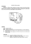
2.2 Mains Connection
All units are generally factory set for operation at 230V. In the event that the mains supply
varies from this, it is necessary to alter the setting of the voltage selector, located on the rear
of the instrument, immediately above the mains socket (→ figs. 1 and 3). The alteration
procedure is as follows:
• Switch off the unit and disconnect the power cable.
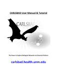
• Draw out the fuse cartridge using a small screwdriver (→ fig. 1),
• Using small pliers/tweezers to pull out the small voltage selection board from the power
•
•
•
•
•
supply module.
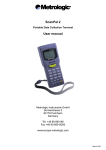
Place the board (writing facing up) under the required voltage selection, as shown in
fig. 2.
Turn the board so that the voltage selection can be seen, as shown in fig. 2.
Adjust the plastic clip as shown in fig. 2 (without turning the board). Ensure that the clip
locates in the notch on the board.
Now, replace the voltage selection board all the way back into the power supply module
(→ fig. 2).
Finally, replace the fuse cartridge.
Important:
Upon installation of the instrument for the first time, the earth connection
and fuses should be checked.
Please note:
For minimum interference effects, all components of the analysis system
should be connected to the same mains output.
Warning:
Before attempting to alter the voltage selection or replace fuses, always
ensure that the power cable is disconnected.
3
Operating Instructions UVD 170S/340S
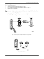
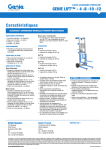
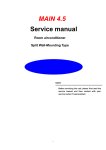
2.2.1 Fuse Replacement
•
•
•
Switch off the unit and disconnect the power cable,
draw out the fuse cartridge using a small screwdriver (→ fig. 1),
replace fuses as appropriate.
Important:
•
•
Only use fuses as indicated in fig. 1 (min. voltage 250 V) or those listed
in the original parts list.
If using US-type fuses, follow the procedure shown in fig. 1.
Replace the fuse cartridge.
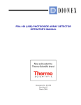
Fig. 1.: Removing the fuse cartridge from the power supply module
Fig. 2: Voltage selection
4
Operating Instructions UVD 170S/340S
2.3 Fluidic Connections
The capillary connections of the UVD 170S/340S are located on the left side of the detector
(→ fig. 6). The input capillary is marked by the black color. Connect this capillary to the
column output.
Please note:
In order to minimize peak-broadening effects due to dead-volume, it
should be ensured that all fluidic connections between sample entry and
detector are of minimum possible length.
Important:
The max. pressure rating of the flow depends on the model (→ Technical
Specifications, page 23). For the standard flow cell, the pressure rating is
100 bar (10,000kPa).
Important:
The flow cell is primed with 2-propanol.
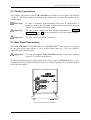
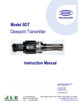
2.4 Rear Panel Connections
The UVD 170S/340S is controlled under the CHROMELEONTM data system via a specific
PC-interface board. Data transfer is via a special cable (order no. 1310.1501) which is
connected at the rear of the unit.
Important:
Use only the original UVD 170S/340S connector cable and extension
(order no. 1310.1502) from Dionex.
The Remote Input provides a digital interface that can be used in CHROMELEONTM, e.g. to
synchronize the Inject signal of an Autosampler (or manual injection valve) with the analysis
start of the data system.
Fig. 3: Rear panel, UVD 170S/340S
5
Operating Instructions UVD 170S/340S
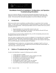
2.5 Installation on the PC-Interface Board
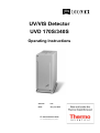
Fig. 4: Address selection on the M68-Interface board
For selection of the I/O-address, the board is fitted with a DIP-switch block (Dual Inline
Package) as shown in fig. 4. The board occupies 4 addresses, starting at the selected base
value which is factory set at 318H. Under normal circumstances, this value need not be
changed unless operating in combination with network and/or other interface boards, the
addresses of which should be confirmed before installation.
Warning:
Ensure that the PC is off and the power cable disconnected before
attempting installation.
Important:
The interface board must be protected against static charge at all times. If
difficulty is encountered fitting the board into the PC, please contact the
Dionex Service.
The board can be inserted in an 8-bit or 16-bit slot.
Please note:
On
Off
1
4
2
3
5
6
On
7
8
Off
4
20 40 80
8
10
100 200
An open switch (OFF) indicates a binary "1", while a closed switch (ON) indicates a binary
"0". On the right, the values are converted into hexadecimal values. Determine the address by
adding the values. The default setting of the UVD 170S/340S interface board therefore has the
following base address:
8 + 10 + 100 + 200 = 318H (hexadecimal).
6
Operating Instructions UVD 170S/340S
3 Overview
The UVD 170S/340S is a high-performance diode-array detector for HPLC detection in the
UV/VIS wavelength range. The unit has been developed exclusively for operation under the
CHROMELEONTM chromatography data system.
The UVD 170S/340S features:
•
Powerful optics, combined with extremely low-noise electronics enable highest
sensitivity.
•
Simultaneous detection on 4 wavelengths, recording of 3D-data fields and the
comprehensive data analysis capabilities within the CHROMELEONTM data system
provide maximum analysis efficiency.
Please note:
The model UVD 170S supports simultaneous detection on 4 wavelengths
if operation is via CHROMELEONTM (from version 4.10). Recording
3D-fields is not possible with this model.
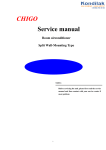
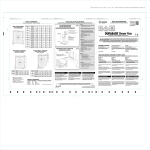
3.1 Principle of Operation
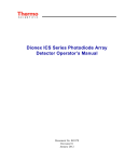
Fig. 5: Principle of operation UVD 170S/340S
7
Operating Instructions UVD 170S/340S
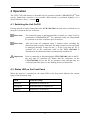
4 Operation
The UVD 170S/340S detector is intended only for operation with the CHROMELEONTM data
system. Stand-alone operation is not possible. Data transfer is performed digitally, via a
special interface cable (→ section 2.4).
4.1 Switching the Unit On/Off
Having ensured all cable connections to the UVD 170S/340S, the unit can be switched on via
the power switch on the rear of the unit.
Please note:
The deuterium lamp is not automatically switched on. Lamp on/off is
performed by CHROMELEONTM. For optimum results, the lamp should
be switched on at least 30 minutes prior to analysis.
Please note:
After the Lamp off command, allow 5 minutes before switching the
deuterium lamp on again. Otherwise, the lamp becomes too hot and could
be damaged (message "Lamp too hot..."). In the event that the PC is
switched off, or the connection cable to the UVD 170S/340S is
disconnected, the deuterium lamp is automatically switched off.
Important:
Prior to connecting or disconnecting the UVD 170S/340S cable to the PC,
the unit must be switched off! Ensure that the connectors on the
UVD 170S/340S and on the PC are inserted evenly and that they are
correctly locked into place via the latching devices on both sides.
4.2 Status LED on the Front Panel
When the detector is switched on, the status LED on the front panel indicates the current
status of the deuterium lamp.
LED
Status D2-Lamp
LED red
Instrument is switched on.
LED green
Deuterium lamp is switched on.
LED off
Instrument is switched off.
8
Operating Instructions UVD 170S/340S
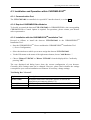
4.3 Installation and Operation within CHROMELEONTM
4.3.1 Communication Port
The UVD 170S/340S is controlled via a special PC-interface board (→ section 2.4).
4.3.2 Required CHROMELEONTM Modules
To be able to control the detector UVD 170S/340S via CHROMELEONTM, the corresponding
CHROMELEONTM Control Option is required. For questions, please contact your Dionex
sales representative.
TM
4.3.3 Installation with the CHROMELEON
Installation Tool
Proceed as follows to install the detector UVD170S/340S in the CHROMELEONTM
Installation Tool:
• Start the CHROMELEONTM -Server and then the CHROMELEONTM Installation Tool
(= Server Configuration).
• Select the timebase to which you want to assign the detector UVD170S/340S.
• Via the Edit menu or the menu of the right mouse button, choose "Add Device... ".
• Choose "Dionex UVD170S" or "Dionex UVD340S" from the displayed list. Confirm by
pressing "OK".
The now displayed tab dialog boxes show the current configuration of your detector.
Generally, these settings must not be changed. However, please check whether the settings
correspond to your current installation environment. If necessary, change settings.
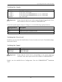
Tab Dialog Box "General"
Option
Device Name
Port Address
Demo Mode
Description
Instrument name under which the detector is listed in the
installation environment (default: UV)
I/O-Base address of the PC interface board (default: 318H)
Deactivate the demo mode!
9
Operating Instructions UVD 170S/340S
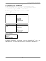
Tab Dialog Box "Signals"
Option
UV_VIS_1
UV_VIS_2
UV_VIS_3
UV_VIS_4
3DFIELD
Important:
Description
UVD 170S / UVD 340S
UVD 170S / UVD 340S
UVD 170S: from CHROMELEONTM v.4.10 / UVD 340S
UVD 170S: from CHROMELEONTM v.4.10 / UVD 340S
only UVD 340S
Ensure that the check boxes of the required channels are activated. If not,
these channels will not be available in CHROMELEONTM.
Select the required signal, and press "Change" to view the following signal parameters:
Signal parameter
Signal Name
Unit
Factor
Description
Signal name
Signal unit of the recorded raw data
current amplification factor
Tab Dialog Box "Error Levels"
In this box you can view the classification of errors in certain error levels. The default settings
must not be altered.
Tab Dialog Box "Inputs"
Option
INPUT170
INPUT340
Important:
Description
only UVD 170S
only UVD 340S
Ensure that the check boxes corresponding to the remote inputs are
activated. If not, these inputs will not be available in CHROMELEONTM.
Finally, save the modified Server Configuration. Close the CHROMELEONTM Installation
Tool.
10
Operating Instructions UVD 170S/340S
4.3.4 Operation within CHROMELEONTM
In CHROMELEONTM, there are two principal modes of instrument operation:
• direct control via the toolbar and menu bar or via controls in the Control Panel
• control via time programs (PGM-file or command buttons)
The following signal-specific and global commands are available.
Signal-specific commands:
Signal type
UV-channel
Parameters
Step
Average
Wavelength
Bandwidth
Ref.Wavelength
Ref.Bandwidth
Signal type
3D-Field (only UVD
340S)
Parameters
Min/Max Wavelength
Bunch Width
Step
Ref.Wavelength
Ref.Bandwidth
Global commands:
Lamp on/off
Autozero
Connect/Disconnect
For detailed information on controlling the detector via CHROMELEONTM, refer to the
CHROMELEONTM User Manual and context-sensitive online Help in CHROMELEONTM.
11
Operating Instructions UVD 170S/340S
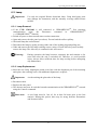
4.3.5 Spectra Calibration under CHROMELEONTM
Under CHROMELEONTM, spectra calibration is performed automatically after each "Lamp
on" or "Connect" command ("detector calibration"). The command "CheckWavelength"
allows you to include the largest wavelength deviation of this calibration in the Audit Trail. A
calibration is possible only when certain conditions are met:
•
•
•
During calibration, the baseline must be sufficiently stable. This may not be the case e.g.
when the solvent composition was modified or when there were air bubbles in the solvent.
The solvent in the cell must not be fully absorbing in the wavelength range which shall be
calibrated. This will be the case e.g. if the cell is filled with 96% hexane / 4 % ethyl
acetate.
Ensure for the calibration that the deuterium lamp is already warm because its spectrum
changes much during the first minutes after switching on the lamp.
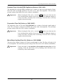
If these conditions are not met, the process will be interrupted with the corresponding error
message. When the problem is solved, repeat the calibration using the command "Disconnect"
first followed by "Connect.
To calibrate the detector, the transmission spectrum of the deuterium lamp is compared with
that of the holmium oxide filter. With the resulting spectrum, the maxima are determined and
compared with the holmium oxide values stated in the literature. If, for a maximum, a
difference is detected between the measured and the known value, an interpolation is
performed between this maximum and the two adjacent maxima to correct the wavelength
allocation of the affected photodiodes. The spectra calibration can take up to 2 minutes.
During this time, data acquisition is not possible.
12
Operating Instructions UVD 170S/340S
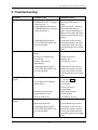
5 Troubleshooting
Problem
Lamp is not switched
on
Probable cause
Lamp is still too hot
(CHROMELEONTM message:
"Lamp too hot...")
Lamp cannot be switched on
( CHROMELEONTM message:
"Lamp On failed...")
Connecting cable between
UVD 170S/340S and PC not
correctly installed
No function
No signal / irregular
signal
Detector not connected to
mains
Detector not switched on
Fuse blown
Replaced fuse blows
immediately
Connecting cable between
UVD 170S/340S and PC not
correctly installed
Flow cell contaminated
Low transmission through
mobile phase
No signal / irregular
signal
Incorrect spectral range
Faulty injection valve
Fault in diode array
Lamp intensity too low
M68 board defective
Connecting cable between
UVD 170S/340S and PC not
correctly installed
13
Remedial action
Allow a delay of 5 minutes,
then switch the lamp on
again.
Allow a delay of 5 minutes,
then switch the lamp on
again. If several attempts are
unsuccessful, check the lamp
and the connecting cable (see
below).
Connectors on the detector
and the PC must be inserted
evenly and locked into place
with latching devices on both
sides.
Connect mains cable
Switch on detector
Replace fuse
Call Dionex service
Connectors on the detector
and the PC must be inserted
evenly and locked into place
with latching devices on both
sides.
Clean flow cell
(→ section 6.3.4)
Select alternative
wavelength
Check solvent for
contaminants.
Alter spectral range
Check fluidics
Call Dionex Service
Change lamp
Check M68 board, replace
Connectors on the detector
and the PC must be inserted
evenly and locked into place
with latching devices on both
sides.
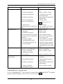
Operating Instructions UVD 170S/340S
Problem
Strong baseline drift
Probable cause
Insufficient warm-up time
Column contaminated
System not equilibrated
Unstable environment
Solvent contaminated
Flow cell contaminated
High noise level
Peak broadening
Analysis is not
reproducible
Lamp defective
Solvent reservoir is placed too
low
Solvent contaminated
Lamp aged
Gas bubbles in system
Pressure pulsation from pump
Solvent reservoir is placed on
the floor
Wrong wavelength
Connecting cable between
UVD 170S/340S and PC not
correctly installed
Capillaries too long or has
excessive internal diameter
Column overloaded,
contaminated or aged
Solvent aging
Sample is unstable
Irreproducible gradient
Unstable environment
Column overloaded,
contaminated or aged
Remedial action
Allow min. 30 min. warmup
Rinse or replace column
Continue to rinse system
until equilibrated
Ensure constant temperature
and humidity
Change solvent
Clean flow cell (→ sec.
6.3.4)
Replace lamp
Place reservoir on the same
level as flow cell
Replace solvent
Replace lamp
Prime system
Check and prime pump
Place reservoir on the same
level as flow cell
Select suitable wavelength
Connectors on the detector
and the PC must be inserted
evenly and locked into place
with latching devices on both
sides.
Shorten or replace for
narrower capillaries
Rinse or replace column
Replace with fresh solvent
Use fresh sample or alter
conditions
Change gradient program /
check pump
Ensure constant temperature
and humidity
Rinse or replace column
CHROMELEONTM Error Messages
A list of CHROMELEONTM error messages is included in the CHROMELEONTM Installation
program on the tab dialog box "Error Levels". See also section 4.3.3.
14
Operating Instructions UVD 170S/340S
6 Maintenance
6.1 General Information
The UVD 170S/340S is constructed only from the highest quality components, thus keeping
maintenance requirements to a minimum. In general, the unit should be kept clean. The
painted surfaces are resistant to solvents as well as weak acid or alkaline solutions. If solvents
or other liquids should be spilled on the surface, these should be cleaned off immediately,
using a lint-free cloth or tissue (avoid rubbing).
The following sections describe all maintenance work which can be carried out by the user.
Any other service or maintenance work should be carried out only by a qualified Dionex
personnel.
In the event that the UVD 170S/340S should require shipment for the purpose of service, this
should be only in the original packing. If no original packing is available, this can be acquired
from Dionex or your local Dionex representative.
Please note:
The warranty coverage shall become invalid in any case identified as
resulting from inappropriate use, service or the implementation of nonspecified spare parts. Similarly, the warranty coverage shall be
invalidated in the event of inappropriate shipment, packaging or failure to
remove aggressive or damaging solvent residues.
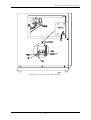
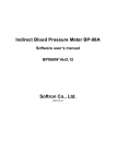
All user serviceable parts (i.e. lamp and flow cell) are accessible via a removable panel,
located on the left side of the unit (→ fig. 6). To open, press in and turn the knurled screw 90o
anti-clockwise. The panel may now be opened and removed. The lamp and flow cell are now
clearly visible.
Warning:
During operation, the lamp becomes extremely hot and remains so for
some time after the unit is switched off. Therefore, to avoid possible
injury, always allow sufficient time for lamp cooling before attempting
any maintenance.
15
Operating Instructions UVD 170S/340S
Fig. 6: Side view, UVD 170S/340S (side panel open)
16
Operating Instructions UVD 170S/340S
6.2 Lamp
Important:
Use only the original Dionex deuterium lamp. Using third party parts
may damage the instrument; and the warranty coverage shall become
invalid.
6.2.1 Lamp Removal
• If the UVD 170S/340S is still connected to CHROMELEONTM, first terminate
•
•
•
•
•
communication
using
the
Disconnect
command
in
CHROMELEONTM
(→ CHROMELEONTM manual).
Switch off power to detector and remove mains connection.
Open and remove the side panel (see above). Do not bend the teflon capillary.
Wait until lamp has cooled down!
Disconnect the lamp by gently pressing either side of the locking plug and pulling out.
Undo and remove the two lamp retaining screws (using a 2.5mm Allen-key) and carefully
remove the lamp. The Allen key is contained in the Accessories.
Warning:
During operation, the lamp becomes extremely hot and remains so for
some time after the unit is switched off. Therefore, to avoid possible
injury, always allow sufficient time for lamp cooling before attempting
any maintenance.
6.2.2 Lamp Replacement
• Insert the new lamp, aligning the notch on its base with the alignment pin of the mounting
and replace the retaining screws. No additional alignment is required.
Important:
Avoid touching the glass tube of the lamp.
• Reconnect cable.
• Replace the side panel.
• The detector may now be switched on and communication with CHROMELEONTM restored
using the Connect command.
Please note:
A new lamp must be "run in" for at least 24 hours prior to the first
analysis. During this period, there may be strong baseline fluctuations
and increased noise.
17
Operating Instructions UVD 170S/340S
6.3 Flow Cell
Important:
The flow cells of the detectors UVD 170S/340S and UVD 160S/320S
are not interchangeable.
Important:
The resistance of the flow cell depends on the solvents. This applies
particularly to solvents which can form active radicals or peroxides.
6.3.1 Flow Cell Versions
The following flow cells are available for the UVD 170S/340S detector:
•
•
•
•
standard flow cell (order no. 5065.1810)
standard flow cell with PEEK capillaries (order no. 5065.1820)
preparative flow cell (order no. 5065.1800P)
micro glass capillary flow cell (order no. 5065.1800M)
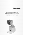
Standard Flow Cell (Order no. 5065.1810)
The standard flow cell of the UVD 170S/340S has a volume of 10µl and a path length of
9mm. The flow cell body is composed of PEEK with quartz windows and is thus 100%
biocompatible. The inlet capillary is factory-fitted with a single-part, handtight fitting. The
outlet is a PEEK capillary. Optionally, a PEEK capillary can be used for the inlet. The
maximum pressure rating of the standard flow cell is 100bar (10,000kPa).
Important:
When cleaning the flow cell (→ section 6.3.4), please note that only the
lens retaining plates and the lenses may be removed. Do not attempt to
remove the flow cell body from its housing! Clean the flow cell body
together with the housing.
18
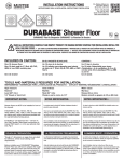
Operating Instructions UVD 170S/340S
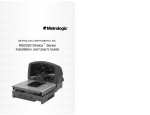
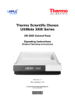
Fig. 7: Standard Flow Cell
No.
1
2
3
4
5
6
7
9
11
12
13
Description
Screw M3x12 DIN965
Heat exchanger
PEEK tubing ID=0.5mm
PEEK fitting screw 1/16", 15 mm
Screw M3x23 DIN 965
Lens retaining plate1
Quartz lens
Lens retaining plate2
Single-part hand-tight fitting
Capillary tube 1,58x0,25 ID
PEEK double ferrule
Order No.
5065.1815
6065.1800
Order No.
included in 5065.1815
included in 5065.1815
2251.6002
included in 5065.1815
included in 6065.1800
5065.1811
1343.0511
5065.1812
included in 5065.1815
included in 5065.1815
2261.0122
Description
Heat exchanger, flow cell, analyt., confg. including:
Heat exchanger
PEEK fitting screw 1/16", 15 mm
Capillary tube 1,58x0,25 ID
Single-part hand-tight fitting
Screw M3x12 DIN965 (2 pcs).
Repair kit, flow cell, analyt. including:
Screw M3x23 DIN 965 (3 pcs.),
Quartz lens (2 pcs.)
Lens retaining plate1 (1 pc.)
Lens retaining plate 2 (1 pc.)
19
Operating Instructions UVD 170S/340S
Standard Flow Cell with PEEK Capillaries (Order no. 5065.1820)
The standard flow cell with PEEK capillaries has a volume of 10µl and a path length of 9mm.
Inlet and outlet are PEEK capillaries. The flow cell is 100% biocompatible. The maximum
pressure rating of the PEEK flow cell is 100bar (10,000kPa).
Important:
When cleaning the flow cell (→ section 6.3.4), please note that only the
lens retaining plates and the lenses may be removed. Do not attempt to
remove the flow cell body from its housing! Clean the flow cell body
together with the housing.
Preparative Flow Cell (Order no. 5065.1800P)
The preparative flow cell for the UVD 170S/340S has a volume of 6µl and a path length of
2mm. The cell body is composed of PEEK and is thus 100% biocompatible. The maximum
pressure rating of the flow cell is 100bar (10,000kPa).
Important:
When cleaning the flow cell (→ section 6.3.4), please note that only the
lens retaining plates and the lenses may be removed. Do not attempt to
remove the flow cell body from its housing! Clean the flow cell body
together with the housing.
Micro/Glass Capillary Flow Cell (Order no. 5065.1800M)
The micro flow cell has a volume of 0.14 µl at a path length of 8 mm. The flow cell body is 100
% biocompatible. The maximum pressure rating of the micro flow cell is 400bar (40,000kPa).
Important:
Please note that it is not possible to disassemble the micro flow cell for
cleaning. Clean the micro flow cell by flushing with 0.2M nitric acid,
followed by water and methanol.
20
Operating Instructions UVD 170S/340S
6.3.2 Flow Cell Removal
• If the UVD 170S/340S is still connected to the data system, first terminate communication
•
•
•
•
using the Disconnect command in CHROMELEONTM (→ CHROMELEONTM manual).
Switch off the detector. Disconnect the power cord.
Open and remove the side panel. Do not bend the Teflon capillary.
Undo the 4 retaining screws and remove the flow cell cover.
Undo the knurled flow cell retaining screw and carefully draw out the flow cell assembly.
Warning:
During operation, the lamp becomes extremely hot and remains so for
some time after the unit is switched off. Therefore, to avoid possible
injury, always allow sufficient time for lamp cooling before attempting
any maintenance.
6.3.3 Flow Cell Replacement
Important:
The flow cells of the detectors UVD 170S/340S and UVD 160S/320S
are not interchangeable.
• Insert the new/cleaned flow cell, aligning the notch with the alignment pin of the mounting.
No further alignment is necessary.
• Replace the flow cell cover.
• Replace the side panel.
• The detector may now be switched on and communication with CHROMELEONTM
restored using the Connect command.
6.3.4 Flow Cell Cleaning
Important:
In contrast to the other flow cell versions, it is not possible to
disassemble the micro flow cell for cleaning. Clean the micro flow cell
by flushing with 0.2M nitric acid, followed by water and methanol.
To clean the flow cell (except the micro flow cell), proceed as described below. The numbers
in parentheses refer to the corresponding parts as illustrated in fig. 7:
• Undo and remove screws (1) and remove the heat exchanger (2).
• Undo and remove screws (5) and carefully remove the lens-retaining plates (6 and 9) and
lenses (7).
• To avoid scratching the lenses, these should be placed on a clean, lint-free cloth or tissue.
• Clean the lenses using a soft, lint-free cloth or tissue and an optical cleaning solution.
• Scratched or damaged lenses must be replaced.
Important:
Do not attempt to remove the flow cell body (8) from its housing (10)!
• Cleaning of the flow cell body together with its housing may be carried out by rinsing with
water, iso-propanol or methanol or by placing the entire assembly into an ultrasonic bath.
21
Operating Instructions UVD 170S/340S
Important:
Never attempt to remove dirt from the flow cell body using a spatula,
tweezers or any other objects as this may lead to irreparable damage.
• Replace the lenses onto either side of the flow cell body so that the flat faces are on the
inside.
• Replace the retaining plates (6 and 9) taking care to tighten the screws (5) evenly and
without excessive force.
• Check the flow cell for leakage before replacement into the unit, tightening screws (5) if
necessary.
22
Operating Instructions UVD 170S/340S
7 Technical Specifications
Optics:
Light source:
Wavelength range:
Pixel bandwidth:
Wavelength accuracy:
Noise:
Drift:
Flow cell volume:
Flow cell pressure rating:
Measuring range:
Time constant:
PC-connection:
Data channels
(UVD 340S):
Data channels
(UVD 170S):
Wetted parts:
Power requirements:
Power consumption:
Dimensions:
Weight:
Operating conditions:
Single beam principle with simultaneous measurement
across the photodiode array.
Deuterium lamp
200nm - 344nm (UV-range)
345nm - 595nm (VIS-range)
1.9nm (UV-range)
3.3nm (VIS-range)
± 0.75nm (UV-range)
± 1.5nm (VIS-range)
< ± 0.8 x 10⁻⁵AU, after 3h warm-up at 254nm,
time step 1sec., empty flow cell
< 5 x 10⁻⁴AU/h, after 3h warm-up at 254nm,
empty flow cell
Standard flow cell:
10µl, 9mm path
Standard flow cell/PEEK capillaries: 10µl, 9mm path
Preparative flow cell:
6µl, 2mm path
Micro capillary flow cell:
0.14µl, 8mm path
Standard flow cell:
100bar (10,000kPa)
Standard flow cell/PEEK cap.
100bar (10,000kPa)
Preparative flow cell:
100bar (10,000kPa)
Micro capillary flow cell:
400bar (40,000kPa)
0AU to 2AU
0.1sec
Proprietary cable
4 (+3D-field with or CHROMELEONTM control option)
4 with CHROMELEONTM as of version 4.10
PEEK, quartz
115/230V ± 10%, 50/60Hz
50VA
210 x 480 x 430mm (w x h x d)
20kg
Temperature: 10°C to 35°C
Air humidity: 40% to 85%
Technical information: October 1998, subject to alteration without notice!
23
Operating Instructions UVD 170S/340S
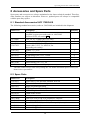
8 Accessories and Spare Parts
Spare parts and accessories are always maintained at the latest technical standard. Therefore,
order numbers are subject to alteration. However, updated parts will always be compatible
with the parts they replace.
8.1 Standard Accessories UVD 170S/340S
The following standard accessories (order no. 5065.9000) are included in the shipment:
Order No.*
1272.0003
1310.1501
1310.7031 or
1310.7032
2146.1051
2146.2625
2261.0121
2261.0122
2309.1100
6007.9100
8005.9001A
*
Description
Quantity
Fuse, 1A, 5 x 20mm
(available as spare part under order no. 6065.9002
Kit Fuses UVD, see section 8.2).
Fuse, 2A, 6.3 x 32mm (for 115V only)
Interface cable, UVD 170S/340S
Power cable (220V), 3 x 0.75mm², 2m
Power cable (115V), 3 x AWG18, 2m
(depending on country)
Spanner ¼“ x 5/16“
Allen-key, 2.5mm
PEEK fitting screw 1/16“, 15 mm
PEEK double ferrule
Accessories container
Silicon tubing (2.8 x 1.3), 3m
Connector cable, remote input/pressure output
2
1
1
1
1
1
2
2
1
1
1
The order number always refers to the packing unit. For further information please contact your
Dionex sales representative.
8.2 Spare Parts
Order No.*
Description
1343.0511
2101.0303
2200.5502
2251.6002
2261.0121
2261.0122
5053.1204
5065.1800P
5065.1800M
5065.1810
5065.1811
5065.1812
Quartz lens UVD170S/340S, standard flow cell
M3 knurled flow cell retaining screw
Single-part, hand-tight fitting
PEEK capillary tube, 1/16“x0.50mm, 1m
PEEK fitting screw 1/16“, 15 mm
PEEK double ferrule
D2 lamp
Flow cell UVD170/340, 6 µl, preparative, complete
Micro/glass capillary flow cell, complete
Flow cell UVD170/340, standard, biocomp., 10µl, complete
Lens retaining plate1
Lens retaining plate2
24
Operating Instructions UVD 170S/340S
Order No.*
Description
5065.1815
Heat exchanger, flow cell, analyt., confg. including:
Heat exchanger
PEEK fitting screw 1/16", 15 mm
Capillary tube 1,58x0,25 ID
Single-part hand-tight fitting
Screw M3x12 DIN965 (2 pcs).
Standard flow cell UVD170/340, 10 µl, PEEK capillaries, complete,
Repair kit, flow cell, analyt. including:
Screw M3x23 DIN 965 (3 pcs.),
Quartz lens (2 pcs.)
Lens retaining plate1 (1 pc.)
Lens retaining plate2 (1 pc.)
UVD 340S / 170S Repair Kit
Quartz lenses (2 pcs)
PEEK capillary tubing 1/16", 0.50 mm (2 m)
PEEK fitting screws 1/16", 15 mm (2 pcs)
PEEK double ferrule (2 pcs)
deuterium lamp D2 (2 pcs)
Kit Fuses UVD including:
Fuse 0.80A, medium-slow, 5x20 mm (1pc)
Overload fuse 1A, slow, 5x20 mm, (2 pcs)
Overload fuse 2A, slow, 5x20 mm (2 pcs)
M68-PC-Interface board
5065.1820
6065.1800
6065.9001
6065.9002
9365.0001B
* The order number always refers to the packing unit. For further information please contact your
Dionex sales representative.
25