1
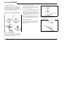
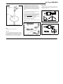
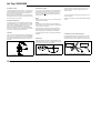
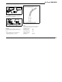
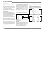
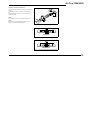
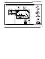
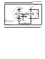
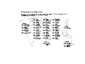
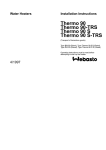
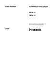
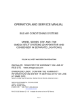
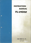
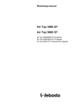
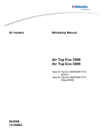
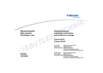
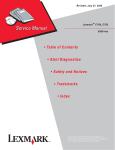
Air Heaters
Installation instructions
Air Top 3500
Air Top 5000
Type Air Top 3500 B (Petrol
Type Air Top 3500 D (Diesel)
Type Air Top 5000 B (Petrol)
Type Air Top 5000 D (Diesel)
12/1998
Air Top 3500/5000
Table of Contents
Page
Installation Instructions
Legal Provisions for Installation
Installation
Installation Example
Heating Air System
Fuel Supply
Combustion Air Supply
Exhaust Pipe
Electrical Connections
Circuit Diagrams
Initial Operation
Shut-Down on Faults
Technical Data
Drilling Template
Webasto Service Phone
II
1
3
5
6
7
10
10
12
15
22
22
23
25
27
Air Top 3500/5000
Installation Instructions
Legal Provisions for Installation
For testing the heater in accordance with §§ 19, 20 or 21
StVZO (German Road Licensing Regulations) the following regulations are primarily to be observed (§ 22 a
StVZO):
NOTE:
These provisions are binding within the scope of the
StVZO and should also be observed in countries
where no special regulations are in effect!
Within the scope of the StVZO (German Road Licensing
Regulations) “General Design Certifications” have been
granted by the Federal Office for Motor Traffic for the Air
Top 3500/5000 air heaters with the following design approval numbers:
~ S 305 Air Top 3500 B
~ S 306 Air Top 3500 D
~ S 304 Air Top 5000 B
~ S 303 Air Top 5000 D
The installation of the heaters must be performed in accordance with these Installation Instructions. The installation must be checked
a) upon the homologation of the vehicles in accordance
with § 20 StVZO
b) upon any individual test in accordance with
§ 21 StVZO, or
c) upon any examination in accordance with
§ 19 StVZO by a registered expert or examiner for
motor traffic, an expert for automotive vehicles,
or any other authorised official, in accordance with
paragraph 7.4 a of Appendix VIII to the StVZO
and in the case of item c) the proper installation must be
certified on the approval certificate contained on the design certification stating the following:
- vehicle manufacturer
- vehicle type and
- vehicle identification number
The effectiveness of the design certification (homologation) is dependent on this certificate. The approval certification is to be kept in the vehicle.
Extracting the combustion air from the interior of the vehicle is not permissible.
“Combustion air pipe: The combustion air required
The year of the initial operation must be durably marked
on the type plate of the heater by the installer by removing
the years that do not apply.
The heat exchanger of the air heater is not to be used
for longer than ten years and must thereafter be replaced by the manufacturer or one of its authorised
dealers with a genuine replacement part.
If exhaust pipes lead through passenger areas, these
pipes must also be replaced with genuine replacement
parts after ten years.
Whenever the heater is removed it is imperative that
the gasket located underneath be replaced.
must be drawn in from the outside of the vehicle.
Inside passenger areas the combustion air lines are permitted to have a maximum of four joints and must be provided with a splash-proof opening leading through the outside wall. These joints must be so sealed that a total leakage rate of 200 l/h at an overpressure of 0.5 mbar is not exceeded.
The pipe including lead-through, joints, material and type
of construction must be specified in the installation instructions.
Mounting and removal of the pipe must be possible with
tools only, the pipe must be protected against damage and
be permanently vibration-proof.
“Exhaust gas pipe”: The heaters must be so designed
The heaters are approved for heating the passenger compartment and the driver’s cabin, not however, the cargo
space for the transport of hazardous materials.
When using the heater in special vehicles (e.g. “TRS” vehicles for the transport of hazardous materials) or in vehicles not subject to StVZO regulations (e.g. ships) all regulations that may be locally applicable are to be complied
with.
When installing the Air top 3500/5000 D heater in vehicles for the transport of hazardous materials the requirements laid down in TRS 002 and TRS 003 (Technical Guidelines relating to the ordinance of transporting hazardous
materials on the road) must be fulfilled in addition to those
of the StVZO.
“Heating air system”:Heating air intake openings must
be so arranged that the possibility of exhaust fumes from
the vehicle engine and the heater being drawn in is remote
under normal operating conditions.
that the exhaust fumes are discharged to the atmosphere.
Exhaust pipes must be so routed that the possibility of exhaust gases penetrating the interior of the vehicle is
remote. The functioning of any parts of the vehicle essential for its operation must not be impaired. Any condensate
or water that may have entered must not be able to collect
in the exhaust gas line. Drain holes are permissible; these
must discharge the liquid to the atmosphere via lines that
are leakproof in relation to the interior of the vehicle.
The discharge opening of the exhaust pipe is to point upward, sideways or, in the case of routing the exhaust pipes
on the underside of the bottom of the vehicle, it must be positioned near the lateral or rear edge of the driver’s cab or
vehicle.
Inside areas where people are present, exhaust pipes may
have a maximum of one joint, and their lead-through
through the outer wall/bottom of the vehicle must be
splash-proof. It is permissible to connect a drain pipe provided with a leak-proof metal joint to discharge the water
penetrated into the exhaust pipe. The drain pipe is to be
passed through the outside wall or the bottom of the ve-
1
Air Top 3500/5000
hicle through a sealed bush.
The heat exchanger, the connected exhaust pipe as well
as any drain pipe that may be connected must be so
sealed that in the event of an overpressure equivalent to
the twofold overpressure of the exhaust gas at maximum
permissible exhaust pipe length – however, at a minimum
overpressure of 0.5 mbar – a leakage rate of a total of 30
l/h is not exceeded.
The pipe including lead-through, joints, material and type
of construction must be specified in the installation instructions.
Mounting and removal of the pipe must be possible with
tools only, it must be protected against damage and be permanently vibration-proof.
Only metal pipes may be used. These must not exceed a
temperature of 110 °C if the possibility of accidental contact in the vehicle’s interior exists. It is permissible to install
a protection against accidental contact.
“Combustion Air Inlet” and “Exhaust Gas Outlet”:
During installation it must be ensured that the openings of
the combustion air inlet and exhaust gas outlet pipes are
so designed that a spherical object of 16 mm diameter cannot be introduced.
Electric lines, switchgear and controlgear of the heater
must be so arranged in the vehicle that their functioning
cannot be impaired under normal operating conditions.
All tubes leading from the heater toward the outside must
be routed through splashwater-proof openings.
In the case of buses, the heater must be installed neither
in the driver’s compartment nor in the passenger area.
For the routing of fuel lines and the installation of additional
fuel tanks, articles 45 and 46 StVZO are to be adhered to.
The most important excerpts therefrom are as follows:
Fuel lines are to be designed in such a way that their stability remains unaffected by torsional stresses in the vehicle, engine movement and the like. They must be protected against mechanical damage. All parts of the fuel system must be protected against heat which would impair
2
their operation, and must be located such that dripping or
evaporating fuel can neither collect nor be ignited by hot
components or electrical equipment.
In the case of buses, fuel lines and fuel tanks may be located neither in the passenger area nor in the driver’s compartment. In these vehicles the fuel tanks must be located
such that they do not pose a direct hazard to the exits in
the event of a fire. The fuel must not be supplied by means
of gravity or gauge pressure in the fuel tank.
Mounting instructions for Webasto fuel tanks for fuel supply of heating units in vehicles:
In the case of buses, installation must not be performed in
the passenger area or in the driver’s compartment.
The fuel filler neck must not be located inside the passenger area or the driver’s compartment in any vehicle.
Petrol fuel tanks must not be located directly behind the
front panelling of the vehicle.
They must be separated from the engine in such a manner
that the possibility of fuel inflammation is remote even in
the event of an accident. This does not apply to tractor vehicles with open cabs.
The operating state of the heater at any given time – i.e. at
least whether it is on or off – must be easily recognizable.
Webasto will not assume any liability if the installation instructions and the notes contained therein are not observed. The same applies to improperly performed repairs
or those where others than genuine replacement parts
have been used. In those cases, the heater’s General Design Certification and thus the vehicle’s General Operating
Permit (homologation) will be invalidated as a consequence.
Air Top 3500/5000
Scope of Application of the Air Heaters
The Webasto Air Top 3500/5000 air heaters are designed
to provide the following features:
- for the heating of driver’s cabs, boats, trucks, small
buses, vans and ambulance vehicles
- defrosting the vehicle’s windows.
The heaters operate independently of the vehicle engine
and are connected to the fuel tank and the electrical system of the vehicle.
They can be used in vehicles with water-cooled or aircooled engines.
Installation
CAUTION:
The legal provisions 1 and 2 relating to the installation are
to be adhered to.
It is not permitted to operate the heater without control unit
cover (results in overheating of the heater).
1
2
3
4
5.
Heating air inlet
Heating air outlet
Combustion air inlet
Exhaust gas outlet
Fuel inlet
Fig. 1:
6
7
8
9
Space required for heating air inlet
Space required for heating air outlet
Space required for removal of heater
Cable outlet (optionally on the right or left)
Dimensions of the Heater
Installation Details for Air Top 3500/5000
NOTE:
The different vehicle-specific installation conditions should
be taken into account.
Installation Location
The heater can be fitted both inside and outside the vehicle. When installed on the outside, care must be taken
that the heater is fitted in a location that is protected
against splashwater and spray.
3
Air Top 3500/5000
If installed in the vehicle’s interior, the lead-through openings for combustion air inlet, exhaust gas outlet and fuel
pipe must be splash-water protected.
A gasket (Fig. 4) must be fitted between heater and car
body. The gasket must be renewed prior to each reinstallation. The support surface for the heater mounting
foot must be level. A special tool is available from the
manufacturer for drilling the holes and levelling the support
surface, if necessary. Surface irregularities of up to max. 1
mm can be compensated for by means of the gasket.
For this purpose, the special gasket supplied with the
heater must be used (see Fig. 4). The gasket must be
renewed prior to each re-installation.
Diesel-fuelled heaters
0 - 90°
0 - 90°
CAUTION:
After the installation has been performed, a check must be
carried out to verify that no part of the housing is in contact
with any surrounding parts. Non-compliance could result in
a blockage of the heater fan.
0 - 90°
Fig. 3:
Hole Pattern
Name Plate
The type plate must be located at a place where it is protected against damage and be easily accessible once the
heater has been installed (or else, a type plate duplicate is
to be used).
petrol-fuelled heaters
0 - 90°
0 - 90°
0 - 30°
Fig. 2:
The years not applicable are to be removed from the type
plate.
Permissible Installation Positions
Fig. 4:
Gasket
Unobstructed installation to be ensured!
Mounting the Heater
When mounting the Air Top 3500/5000 heater, the M 6 nuts
must be tightened to a torque of 6 Nm +1 Nm.
The mounting dimensions as well as the space required
for the performance of servicing work are shown in the installation drawing (Fig. 1). The specified horizontal and
axial angles of inclination must not be exceeded (Fig. 2).
4
Fig. 5:
Installation
Air Top 3500/5000
1
2
3
4
5
6
7
Heater control dial
Heater
Metering pump and damping device
Fuel filter (accessory)
Tank extracting device
Exhaust silencer (accessory)
Fuse
1
7
2
3
4
5
6
Fig. 6:
Installation example of air heater in the recirculating air mode
5
Air Top 3500/5000
Heating Air System
NOTE:
It is not permissible to integrate the heater into the vehicle’s air ducting system.
Both recirculated-air and fresh-air operation is permissible.
In the case of fresh-air operation, care must be taken that
the heating air is extracted from an area that is protected
against splashwater and spray.
NOTE:
In the case of fresh-air operation, an external temperature
sensor must be mounted within the space to be heated.
A temperature sensor is installed in the heater on the heating air intake side which, in conjunction with the heater control element and dependent upon the intake temperature
and position of the setpoint transmitter, operates the
heater within the appropriate heat output range. Heat output is so adjusted that after a quick reaching of the preset
interior temperature the same will be maintained at the
preset value.
Minimum inside diameter of heating air pipe is
90 mm at Air Top 5000
80 mm at Air Top 3500
may be decreased to 75mm subject to prior approval by
the manufacturer.
NOTE:
For heating air ducts only materials capable of withstanding a temperature of at least 150° may be used.
The hot air discharge opening is to be located so that the
hot air is not directed onto parts that are not resistant to
heat.
CAUTION:
In vehicles designed for the transportation of passengers,
the air outlet openings must be arranged in such a way
that they cannot be obstructed by passengers.
6
Maximum air pressure drop between intake and delivery
side of the heating air line:
Air Top 3500 2,0 mbar (20 mm WH)
Air Top 3500 Volume Plus 3,0 mbar (30 mm WH)
Air Top 5000 3,0 mbar (30 mm WH)
The test can also be performed by measuring the temperature directly at the heater:
temperature difference between heating air inlet and hot
air outlet max. 130 K.
If this value is exceeded, the temperature limiter is expected to trip. The heating air hose is to be secured at the
joints.
The hot air stream must be prevented from re-entering the
heater, if the heater is operated in the recirculating mode
without any hot air ducting
Fig. 7a:
Heating air inlet with intake grille
If an installation housing is used, the area around the air
discharge nozzle must be tightly sealed so that no hot air
can enter the installation box.
External Temperature Sensor
Fig. 7:
Heating air inlet and heating air outlet
CAUTION:
If the heater is operated without heating air intake hose, it
is imperative that the air intake grille supplied with the
heater be mounted!
NOTE:
The installation must be checked for the following:
- “closed circuit” of air between the vehicle heater and the
heater air inlet
- “closed circuit” of air between heater air inlet and heater
air outlet (fig. 7)
- adequate space for taking in heating air (heating air to be
extracted from the cool space of the cabin, e.g. in the
case of installation underneath a bunk)
The installation of an external temperature sensor is recommended if the heater is installed in an installation housing or in location with poor ventilation (e.g. under-neath
bunks). Extremely short cycle times of the heater can thus
be avoided.
Mounting of External Temperature Sensor
The external temperature sensor must be mounted on surfaces as vertical as possible, at mid-height in the vehicle
cab in the area to be heated.
The temperature sensor must not
- be located directly in the hot air stream (vehicle’s or
heater’s heating air).
- be mounted in the vicinity of heat sources
(e.g. vehicle’s heating system).
- be exposed to direct sun radiation (e.g. on the
dashboard).
- be mounted behind curtains or the like.
Air Top 3500/5000
Fuel Supply
Fuel is extracted from the vehicle’s fuel tank or a separate
fuel tank. The values relating to the permissible pressure
at the fuel extraction point are shown in Fig. 8.
permissible fuel feed height
H (m)
at max. permissible
overpressure (bar) in fuel
line
0.00
0.2
1.00
0.11
2.00
0.03
permissible fuel suction
height S (m)
at max. permissible
underpressure (bar) in fuel
tank
0.00
-0.10
0.50
-0.06
1.00
-0.02
l2
l1
l2
l1 + l2 ≤ 10 m
l1 ≤ 1,2 m
l2 ≤ 8,8 m
Fig. 8:
l1
Fuel Supply
7
Air Top 3500/5000
Vehicles with Carburetor Engines
Vehicles with Fuel Injection Engines
In passenger cars, fuel may only be extracted with the special Webasto fuel pickup (see Fig. 8) and as close to the
tank as possible. The connection can be made either in
the flow or the return pipe whereby it must be ensured that
the return pipe reaches almost to the bottom of the tank.
Failing this, the return pipe can be extended.
When installing the heater in vehicles with petrol injection
systems it must be determined whether the fuel pump is
mounted inside or outside the tank.
The fuel pickup is to be so mounted that any air or gas
bubbles are automatically discharged into the tank (see
Fig. 9).
hole pattern
Where the fuel pump is located inside the tank, the fuel
can only be drawn from the return pipe and only by using
the Webasto fuel pickup (see Fig. 8) whereby it must be
ensured that the return pipe reaches almost to the bottom
of the tank (minimum distance to tank bottom, see Fig. 10).
Failing this, the Webasto tank extracting device (see Figs.
9, 10 and 11) can be used.
Where the fuel pump is mounted outside the tank, the fuel
may only be extracted between the tank and the fuel pump
and also only by using the Webasto fuel pickup (see Fig. 8).
minimum distance 25 mm
Fig. 10:
*
Webasto Tank Extracting Device
tank extracting device only to be used with
metal fuel tanks
Vehicles with Diesel Engines
Fuel must be drawn from the fuel tank or a separate tank
(see Figs. 9, 10 and 11). With this method of fuel being
supplied from a separate tank, no pressure-related influence is possible.
plastic tank
to engine
sealing ring
from tank
to metering pump
Fig. 9:
Webasto Fuel Pickup
Fuel should not be extracted in the vicinity of the engine
since here gas bubbles are likely to form in the lines owing
to the heat radiation of the engine, which may result in malfunctions of the combustion operation.
8
Fig. 11:
Fuel Extraction From the Plastic Tank
(Extraction Via Tank Drain Plug)
Air Top 3500/5000
fuel extracting
device
sealing ring
the inside diameter must not exceed a given dimension.Starting with an inside line diameter of 4mm, air or
gas bubbles will accumulate resulting in malfunctions of
the combustion operation if lines sag or are routed with a
downward pitch. When the diameters shown in Fig. 8 are
used, you can be sure that no unwanted bubbles will be
formed.
Metering Pump
The metering pump is a combined delivery/metering and
shutoff system and is subject to certain installation criteria
(see Figs. 8, 14 and 15).
Air Top 3500/5000, 12-volt Petrol
The lines leading from the metering pump to the heater
should not be routed in a downward pitch.
tank fitting
To prevent the fuel lines from sagging, freely suspended
lines must be secured. Mounting should be performed in
such a manner that the lines are protected against flying
stones and thermal influence (exhaust pipe).
To prevent the fuel lines from slipping off they are to be secured at the joints by means of hose clamps.
preferably
15°-90°
Connecting Two Pipes Using a Hose
The proper connection of fuel lines using a hose is shown
in Fig. 13.
Check for leakage!
Fig. 14:
Metering Pump DP 2
Installation Position
correct
Air Top 3500/5000 D. 12-volt and 24-volt Diesel
Fig. 12:
Fuel Extraction From the Plastic Tank
(Extraction Via Tank Fitting)
clamp
incorrect
NOTE:
The fitting must be made of sheet steel!
bubble
bubble
Fuel Lines
Only steel, copper and plastic pipes made of plasticized,
light-resistant and temperature-stabilized PA 11 or PA 12
(e.g. Mecanyl RWTL) in accordance with DIN 73378 may
be used as fuel lines. As in the majority of cases it is not
possible to route the lines in a continuous upward pitch,
Fig. 15:
Fig. 13:
Pipe/Hose Connection
Metering Pump DP 30
Installation Position
9
Air Top 3500/5000
Installation Location
Combustion Air Supply
The metering pump must be mounted in a cool location as
close to the tank as possible (see Fig. 8). The permissible
ambient temperature must not exceed a temperature of +
20°C at any given operating state.
Metering pump and fuel lines must not be mounted within
the radiation range of hot vehicle parts. If necessary, a radiation protection is to be provided.
On no account may the combustion air be extracted from
areas where persons are present. The combustion air intake opening must not point in the direction of travel. It
must be so located that the possibility of clogging due to
contamination n is remote.
Installation and Mounting
NOTE:
With an intake duct length < 0.6 m, it is compulsory that an
intake silencer be mounted.
The metering pump is to be attached by a vibration-damping suspension device (e.g. rubberized clamp). The installation position is restricted as shown in Figs. 14 and 15 in
order to ensure proper self-bleeding of the system.
Owing to the hazard of corrosion, only genuine Webasto
parts may be used for the plug connection between metering pump and metering pump cable harness.
NOTE:
Combustion air must be drawn from a splash-water protected location that is as cool as possible. A combustion air
line is to be used, if necessary.
Fuel Filter
For further regulations refer to the Legal Provisionsfor the
installation.
If dirt in the fuel must be reckoned with, only Webasto filter,
order no. 487 171, should be used. The filter is preferably
be installed in vertical position, where this is not possible, it
may also be installed horizontally (direction of flow to be
observed).
The exhaust pipe is to be secured to the heater, e.g. by
means of a clamp. For further regulations refer to the
Legal Provisions.
The exhaust silencer is preferably to be mounted in the vicinity of the heater.
Operation of the heater is also permissible without exhaust
silencer.
Exhaust gas pipes must not be used as combustion air
lines as this would cause damage to the metering pump
cable emerging from the combustion air intake fitting.
Exhaust Pipe
Combustion Air Intake and Exhaust Pipes
Both pipes leading away from the heater are to be routed
in a downward pitch. If this is not possible, a ø 4mm condensate drain hole is to be provided at the lowermost point.
Rigid pipes made of unalloyed or alloyed steel with a minimum wall thickness of 1.0 mm, or flexible tubes of alloyed
steel only are to be used as exhaust pipes.
0 - 90°
Fig. 16: Fuel Filter
10
Fig. 17: Exhaust Silencer
Direction of flow optional
Fig. 18:
Prevent condensation from forming
Air Top 3500/5000
The lines must not point into the direction of travel.
Fig. 19:
To ensure an angle of discharge of 90° ± 10°, it is required that the pipe clamp be attached no more than
150 mm, from the exhaust pipe end
Pipe discharge openings not in direction of
travel
The lines must be so arranged that any clogging due to
contamination is not to be expected.
direction of discharge approximately vertical 90° ± 10°
Fig. 21:
Fig. 20:
Avoid areas exposed to water, mud or snow
CAUTION:
A fire hazard exists if the installation position of the exhaust pipe discharge opening differs from that shown in
Fig. 21.
Length of combustion air intake and exhaust pipes:
with exhaust gas silencer:
max. 2.6 m
without exhaust gas silencer: max. 5.6 m
Exhaust Pipe Discharge Opening
Installation Position
NOTE:
For exhaust pipes lengths of 2 m and more, insulated exhaust pipes are to be used (dew point not reached)
Inside diameter of pipes:
Combustion air pipe:
Exhaust pipe (metal):
25 mm
24 mm
Smallest bending radius:
50 mm
Total angle of all bends:
Combustion air pipe:
Exhaust pipe:
max. 270°
max. 270°
11
Air Top 3500/5000
Electrical Connections
All pipes that are not required must be insulated!
NOTE:
When using the combination or standard digital timer a
remote-control pushbutton may be provided near the bunk
for added convenience. The connection is to be performed
in accordance with wiring diagram 30 and 31.
The electrical connection is to be performed in accordance
with the system circuit (Fig. 29, 30, 31, 32, 33).
Connection in Vehicles for the Transportation of Dangerous Goods (TRS)
When installing the Air Top 3500/5000 D heaters in vehicles for the transport of hazardous materials, the requirements laid down in TRS 002 and TRS 003 (Technical Guidelines relating to the ordinance of transporting hazardous
materials on the road) must be fulfilled in addition to those
of the StVZO. The electrical connection is to be performed
in accordance with wiring diagrams Fig. 32 or 33.
On vehicles without auxiliary drives, electrical connection
is to be performed in accordance with the system circuit diagram Fig. 33.
NOTE:
Switch S3 must be so installed that in the event of a pumping device being put into operation, a plus potential is applied across the corresponding input of the electronic control unit.
CAUTION:
If no voltage to ground is present at the control unit input
X6/1 upon start-up all TRS functions will be inoperative.
After the plus potential has been applied across the control
unit input X6/1 (auxiliary drive ON) a short after-run period
of 20 seconds takes place and subsequently the control
unit is in its “fault lock-out” state.
12
CAUTION:
In accordance with the Technical Guidelines relating to the
ordinance of transporting hazardous materials on the road,
heaters may only be switched on by means of a special
switch installed in the driver’s cabin and are to be actuated
manually. If the heater is equipped with a combination or
standard digital timer, it must ensured that pin 4 on the
combination or standard digital timer remains unassigned.
The heater can therefore only be started up by means of
the instant heating button.
No other digital timers are allowed to be used in TRS vehicles.
Connection to Supply Voltage
Preferably to be supplied from the vehicle central electrical
system.
To provide the heater with adequate protection, an additional flat fuse holder is to be installed (supplied
with the heater). The fuse holder may only be installed
in the vehicle interior.
Connection of the Heater
To connect the cable harness, remove the control unit
cover on the heater and connect the cable harness connectors with the control unit.
Fig. 23:
Removal of Mounting Plate of Fuse Holder
F = 15A (24V)
F = 20A (12V)
Fig. 22:
Removal of Control Unit Cover
NOTE:
Lift off control unit cover applying a blunt edge at its side
(see arrows in Fig. 22)
Be sure not to touch the printed conductors of the
control unit.
Prior to starting up the heater for the first time, reinstall the
control unit cover to prevent any undue escaping of heating air (overheating of heater).
Cable lead-through can optionally be located on the left or
right.
To ensure that the cable lead-through in the control unit
cover provides a tight seal, the cable grommet on the
cable harness must be displaced accordingly.
Fig. 24:
Fuse Holder, Installation Position
Air Top 3500/5000
Connection of Heater Control Element
The cable harness is prepared for connection to the heater
control.
To withdraw the connector pull at the connector housing
only.
If the cable harness is pulled, the connector housing is
locked (self-locking).
NOTE:
The optical fiber must be in contact with the rotary knob.
NOTE:
As an option, an external temperature sensor can be installed in the passenger area (see page 6)
Fig. 25:
Heater Control Knob
Fig. 26:
Mounting of Heater Control Knob
Correct!
Incorrect!
Fig. 27:
Mounting of Heater Control Knob (incorrect)
13
Air Top 3500/5000
Jumper
Terminal 15
Terminal 30
Terminal 58
Terminal 31
to isolate
Fig.28:
14
Connection diagram Air Top 3500/5000 ; only connection featuring a combination timer is shown.
Air Top 3500/5000
ϑ
Fig.29:
ϑ
System circuit diagram Air Top 3500/5000, 12V/24V with Control Knob, legend see page 20 and 21
15
Air Top 3500/5000
ϑ
Fig.30:
16
System circuit diagram Air Top 3500/5000, 12V/24V with Combination Timer , legend see page 20 and 21
ϑ
Air Top 3500/5000
ϑ
Fig. 31:
ϑ
System circuit diagram Air Top 3500/5000, 12V/24V with Combination Timer and electrical battery disconnecting switch, legend see page 20 and 21
17
Air Top 3500/5000
ϑ
Fig.32:
18
ϑ
System circuit diagram Air Top 3500/5000 D, 24V TRS-Operation with Heater Control Knob , legend see page 20 and 21
Air Top 3500/5000
ϑ
Fig. 33:
ϑ
System circuit diagramAir Top 3500/5000 D, 24V TRS-Operation with Heater Control Knob without auxiliary drive , legend see page 20 and 21
19
Air Top 3500/5000
Legende for circuit diagrams:
➀
Positive voltage from terminal (15/75) to pin 10:
continuous operation in the instant heating mode as
long as ignition is switched on
Min. wire cross sections per circuit
< 7.5 m
7.5 - 15 m
2
No positive voltage at pin 10:
variable heating times can be programmed
(10 min up to 120 min),
basic setting: 120 min
➁
➂
➃
➄
➅
➆
0.75 mm
2
1.0 mm
2
1.5 mm
2
Diagnostic K conductor
2.5 mm
2
Diagnostic L conductor
Input pin (pin 7/connector X7, cable color in cable harness: white/red):
“Ventilation” (blower speed is dependent on the heater control position)
CO2 setting (see Workshop Manual)
NOTE:
If connection is made to terminal 30, continuous heating operation is
possible with the ignition turned off! In this case, no connection to
terminal 15/75 must be made!
NOTE:
For TRS function, gray and purple wires are required.
20
4.0 mm
2
1.5 mm
2
1.5 mm
2
2.5 mm
2
4.0 mm
2
6.0 mm
Colour of cables
bl
br
ge
gn
gr
or
rt
sw
vi
ws
blue
brown
yellow
green
gray
orange
red
black
violet
white
Air Top 3500/5000
Pos.
A1
A2
B2
B3
E
F1
F2
F3
H1
H3
Designation
Heater
Electronic control unit
Temperature sensor
Temperature sensor (limiter)
Glow plug / Flame detector
Fuse24V 15A/12V 20A
Fuse20A
Fuse max. 15A
LED green (in Pos. S1)
LED red (in Pos. P)
H4
H5
H6
M1
M3
P
S1
S2
S3
Heating symbol in display (in pos. P)
Lamps (in pos. P)
Lamp (min. 1.2W)
Motor
Motor
Combination timer (1531)
Control element
Disconnecting switch 1 or 2 poles.
Switch
Remarks
Air Top 3500/5000
Overheating protection
flat fuse SAE J 1284
flat fuse SAE J 1284
flat fuse SAE J 1284
operation indicator
Display illumination instant heating button
Operation indicator Operation indicator
light
Operation indicator
Illumination of display and buttons
Operation indicator light pumping device
Combustion and heating air fan
Vehicle fan
Digital timer and setpoint generator
Setpoint generator switch
Emergency Stop switch
at or for pumping device
Pos.
S6
S7
S8
V1
V2
X1
X2
X3
X4
X5
X6
X7
X8
X9
X10
X11
X12
Y1
Y2
Designation
Switch
Push-button switch
Battery disconnecting switch.
Diode
Diode
Connector 2pole
Connector 2pole
Connector 2pole
Connector 2pole
Connector 2pole
Connector 2pole
Connector 12pole
Connector 2pole
Connector 4pole
Connector 2pole
Connector 2pole
Connector 12pole
Metering pump,
Solenoid valve
Remarks
Ventilation
Instant heating button remote control
atPos. A2 (ST B)
at Pos. A2 (ST V)
at Pos. A2 (ST U)
at Pos. A2 (ST Z)
at Pos. A2 (ST Y)
at Pos. A2 (ST X)
at Pos. A2 (ST1)
at Pos. S1
at Pos. Y1
at Pos. P
for pumping device
21
Air Top 3500/5000
Initial Operation
Shut-Down on Faults
Fault Code Display
After the heater has been installed, the fuel supply system
is to be bled thoroughly.
Faults related to individual heater components and malfunctions during the start-up sequence are detected in the
control unit.
If the heater is equipped with a combination or standard
digital timer, a fault code is indicated on the display of the
digital timer whenever a malfunction has occurred:
The heater is shut down (fault lock-out) in the following
cases:
- no or unsuccessful start-up
- temperature sensor defective
- temperature limiter (interruption or short-circuit)
- glow plug defective
- insufficient fan speed, short circuit or interruption
- fault in the metering pump circuit or overheat protection
circuit (during start-up phase only)
- undervoltage of less than 10 volts or overvoltage of
more than 15 volts and for longer than 20 seconds
(aplies to 12-volt heaters)
- undervoltage of less than 20 volts or overvoltage of
more than 32 volts and for longer than 20 seconds
(on 24-volt heaters)
- control unit defective
- overheating
F
00
F
01
F
F
F
F
02
03
04
06
F
07
F
08
F
09
F
F
10
11
Fuel supply will be interrupted in the event of overheating.
An after-run cycle is performed as is the case when the
heater is shut down manually.
After the after-run cycle has been terminated, the control
unit is in the fault lock-out state.
An overheating condition is indicated by 10 flashing light
signals of the operation indicator.
Eliminate cause of malfunction.
To deactivate the fault lock-out, the heater is to be briefly
(min. 2 seconds) turned off and then switched back on
again one time.
F
12
NOTE:
Owing to the low fuel consumption it is required that the
heater be turned on repeatedly to fill the fuel line leading to
the heater.
During a test run of the heater all connections are to be
checked for leakage and security. Should a malfunction of
the heater occur during operation, fault isolating measures
are to be performed.
22
Control unit failure / incorrect parameter set /
warm start detection
No start-up (after 2 start-up attempts)
no formation of flames
Flame extinguished (repeated >5)
Undervoltage or overvoltage
Premature flame detection
Temperature sensor interruption or
temperature sensor short-circuit
Metering pump interruption or
metering pump short-circuit
Fan motor interruption or
fan motor short-circuit or
fan motor incorrect speed
Pencil-type glow plug interruption or
pencil-type glow plug short-circuit
Overheating
Temperature limiter interruption or
temperature limiter short-circuit
Setpoint transmitter (interruption / short-circuit)
Air Top 3500/5000
Technical Data
Unless tolerances are shown within the technical data
table, a tolerance of ± 10% applies at an ambient temperature of +20°C and at the rated voltage and conditions.
Electrical Components:
Control unit, motor, fuel metering pump, light bulb in the
digital timer* and pencil-type glow plug/flame detector are
designed either for 12-volt or 24-volt operation.
Heater
Operation
Mark of approval
~S 305
Type
Heat output
control range 1,5 – 3,5 kW
Fuel
Fuel consumption
*booster setting for max. 30 min.
Rated voltage
* Presetting of heater operating times is not possible for
TRS-operation
Fuel for AT 3500/5000 B (Petrol):
The fuel specified by the vehicle manufacturer is suitable
as fuel for the heater.
Fuel for AT 3500/5000 D (Diesel/Fuel Oil EL):
The Diesel fuel specified by the vehicle manufacturer is
suitable as fuel for the heater. Also EL class fuel oil – not,
however, L type fuel oil – can be used provided it conforms to the usual quality on the German market in accordance
with DIN 51603.
Any negative effect caused by additives is not known.
When the fuel for the heater
is drawn from the vehicle’s fuel tank, the vehicle manufacturer’s specifications concerning additives are to be observed.
When to changing to cold-resistant fuels, the heater must
be operated for approx. 15 minutes to ensure that the fuel
pump is filled with the new fuel.
Operating voltage range
Rated power consumption
Air Top
3500 D
Air Top
3500 D
Volume
Plus
Air Top
5000 B
Air Top
5000 D
~S 306
~S 306
~S 304
~S 303
air heater with vaporizing type burner
control range
The digital timer*, temperature limiter and temperature sensor are voltage-independent components.
Air Top
3500 B
control range
1,5 – 3,5 kW
petrol
Diesel
petrol
Diesel
0,17 – 0,46
l/h
0,17 – 0,42 l/h
0,19 – 0,66
l/h
(0,73)* l/h
0,17 – 0,60
l/h
(0,66)* l/h
12 volts
12/24 volts
12 volts
12/24 volts
10,5 – 15
volts
10,5–15/21–30 volts
10,5 – 15
volts
10,5–15/21–30
volts
15 – 90 W
15 – 90 W
218 m3/h
218 m3/h
15 – 36 W
15 – 36 W
Permissible ambient temperature:
Heater:
- operation
- storage
Metering pump- operation
- storage
Heater control - operation
- storage
Perm. combustion air intake
temperature
Setting range for interior
temperature
Flow rate of heating air against
0.5 mbar
CO2 content in exhaust gas
(permissible operating range)
Dimensions of heater
Weight of heater
1,5 – 5,0(5,5)* kW
*booster setting for max.
30 min.
15 – 90 W
-40°... +40°C
-40°... +85°C
-40°... +20°C
-40°... +85°C
-40°... +75°C
-40°... +85°C
-40°... +20°C
+10 ... + 45 °C
139 m3/h
139 m3/h
218 m3/h
1,5 kW:5,0-8,0%
3,5 kW:9,0-12,5%
1,5 kW:5,0-8,0%
5 kW:9,0-12,5%
length 425 ± 2 mm
width 148 ± 1 mm
height148 ± 1 mm
5,9 Kg
23
Air Top 3500/5000
Version
Air Top 3500/5000 B (Petrol)
Type Air Top 3500/5000 B
Air heaters for petrol fuel
(12 volts)
Air Top 3500/5000 D (Diesel)
Type Air Top 3500/5000 D
Air heaters for
“Diesel/EL Fuel Oil EL”
(12 or 24 volts)
Air Top 3500 Volume Plus D
(Diesel)
Type Air Top 3500 D
Air heaters for
“Diesel/EL Fuel Oil EL”
(12 or 24 volts)
24
Air Top 3500/5000
Gasket
NOTE:
Max. floor unevenness in the
vicinity of the gasket: 1mm
Fig. 34:
Drilling template
25
Air Top 3500/5000
26
subject of modification
Webasto Thermosysteme GmbH
82131 Stockdorf . Kraillinger Str. 5 . Telefon (089) 85794-0
Telefax (089) 8 57 94-448 . Telex 5 23 647 webas d