1
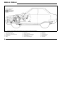
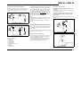
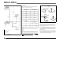
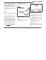
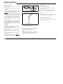
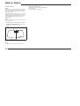
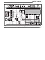
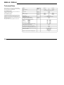
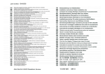
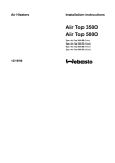
Water Heaters
Installation Instructions
BBW 46
DBW 46
Be sure to read these Operating Instructions
prior to putting the heater into operation.
9/1998
BBW 46 / DBW 46
Table of Contents
Page
Installation Instructions
1
Legal Provisions
1
Installation Location
2
Installation Example
BBW 46 / DBW 46
3
Connection to the Cooling System 5
Re-Positioning of Circulating Pump 5
Fuel Circuit Connection
5
Combustion Air Supply
8
Exhaust Gas Pipe
8
Electrical Connections
8
Allocation of Telestart T60
9
Installation of Telestart Receiver 9
Circuit Diagrams
12
Initial Start-Up
13
Technical Data
14
Version
15
I
BBW 46 / DBW 46
Installation Instructions
Legal Provisions for Installation
For testing the heater in accordance with Section 19, 20 or
21 StVZO (German Regulations Authorising the Use of Vehicles for Road Traffic) the following regulations are primarily to be observed (Section 22 a StVZO):
NOTE:
These provisions are binding within the scope of the
StVZO and should also be observed in countries
where no special locally applicable regulations are in
effect!
Within the scope of the StVZO ”General Design Certifications” have been granted by the Federal Office for Motor
Traffic for the BBW 46 and DBW 46 water heaters with the
following design approval numbers:
~ S 185 for heaters BBW 46 - petrol
~ S 186 for heaters DBW 46 - diesel
The installation of the heaters must be performed in accordance with these Installation Instructions. The installation must be checked
a) upon the homologation of the vehicles
in accordance with Section 20 StVZO
b) upon any individual test
in accordance with Section 21 StVZO, or
c) upon any examination
in accordance with Section 19 StVZO by a
registered expert or examiner for motor traffic, an
expert for automotive vehicles, or any other
authorised official, in accordance with Paragraph
7.4 a of Appendix VIII to the StVZO,
and in the case of item c) the proper installation must be
certified on the approval certificate contained on the design certification stating the following:
- vehicle manufacturer
- vehicle type and
vehicle identification number.
The effectiveness of the design certification is dependent
on this certificate. The approval certification is to be kept in
the vehicle.
The year of initial operation must be durably marked by the
installer on the type plate of the heater by removing the
years that are not applicable.
Extracting the combustion air from the interior of the
vehicle is not permissible.
The discharge opening of the exhaust pipe should point upward, sideways, or in the case that the exhaust pipes are
routed on the underside of the bottom of the vehicle, it
must be positioned near the lateral or rear edge of the
driver’s cab or vehicle.
Exhaust pipes must be routed so that the possibility of exhaust fumes entering the interior of the vehicle is remote.
The functioning of any parts of the vehicle essential for its
operation must not be impaired.
orating fuel can neither collect nor be ignited by hot components or electrical equipment.
The heater must not be installed in spaces occupied by
persons.
The operating state of the heater at any given time – at
least an indication as to whether it is “on” or “off” - must be
easily recognisable.
The installation of components which are not of an approved type will lead to the revocation of the General Design Certification of the heater and thus the General Operating Permit of the entire vehicle. The same applies to improperly performed repairs or those where other than genuine replacement parts have been used.
The openings of the combustion air inlet and exhaust gas
outlet pipes must be so designed that a spherical object of
16 mm dia. cannot be introduced.
Electric lines, switchgear and controlgear of the heater
must be so arranged in the vehicle that their functioning
cannot be impaired under normal operating conditions.
For the routing of fuel lines and the installation of additional fuel tanks, Sections 45 and 46 StVZO are to be
adhered to. The most important excerpts therefrom are as
follows:
Fuel lines must be designed in such a way that they remain unaffected by torsional stresses in the vehicle, engine movement, and the like. They must be protected
against mechanical damage. All parts of the fuel system
must be protected against heat which would impair their
operation, and must be located such that dripping or evap-
Use of the Water Heater
The BBW 46 / DBW 46 water heaters, in conjunction with
the vehicle’s heating system, are used for
- heating the passenger compartment,
- defrosting the vehicle’s windows,
- preheating water-cooled engines.
The water heaters operate independently of the vehicle’s
engine and are connected to the cooling system, the fuel
system and the electrical system of the vehicle.
1
BBW 46 / DBW 46
Installation Location
2
Preferably, the heater should be installed in the engine
compartment in the splash-water protected area of the
front fenders or at the splash wall.
The heater should be installed at a level as low as possible
so as to ensure automatic venting of the heater and the circulating pump. . This is of special importance since the circulating pump is not of the self-priming type.
2
1
6
CAUTION:
The openings of the water connecting pipe sockets must
never, not any installation position, point downward.
4
3
4
CAUTION:
The heater must not be installed :
- in the immediate vicinity of or above hot vehicle parts
- in the direct splashwater area of the wheels
5
1
2
3
4
5
6
Fig 2:
Fig 1:
Fuel inlet
Water outlet
Water inlet
Exhaust gas outlet
Heater mount
Combustion air inlet
Installation Drawing BBW 46 / DBW 46
Installation Positions
Type Plate
Mount
The type plate must be located at a place where it is protected against damage and where it can be easily viewed
once the heater has been installed (or else, a type plate duplicate is to be used).
The years not applicable must be removed from the type
plate.
The heater mount must be fitted to the vehicle body or the
intermediate support by means of at least four M6 screws.
In the case of level body surfaces, the washers must have
a minimum diameter of 22 mm.
It is required that washers and lock washers be used.
Do not use sheet metal screws for attaching the mount.
2
BBW 46 / DBW 46
Cable harness
Fuel line
Heater fuel line
Exhaust gas line
Water circuit
Fig 3:
1
2
3
4
5
6
7
Installation example of BBW 46 / DBW 46 heating device in a passenger car (inline integration)
Radiator
Cooling water thermostat
Water pump (of vehicle engine)
Vehicle engine with standard equipment
Water heater
Battery
Fuse holder
8
9
10
11
12
13
14
Control unit
Relay (for vehicle fan)
Regulating valve of vehicle heating
Heat exchanger of vehicle heating
Vehicle heating fan
Switch for vehicle heating fan
Fuse bank in vehicle
15
16
17
18
19
Digital timer
Fuel extractor
Fuel metering pump
Exhaust silencer
Circulating pump
3
BBW 46 / DBW 46
Cable harness
Fuel line
Heater fuel line
Exhaust gas line
Water circuit
Fig 4:
1
2
3
4
5
5A
6
4
Installation example of BBW 46 / DBW 46 heating device in a passenger car (thermostat integration)
Radiator
Cooling water thermostat
Water pump(of vehicle engine)
Vehicle engine with standard equipment
Water heater
Non-return valve
Battery
7
8
9
10
11
12
13
Fuse holder
Control unit
Relay (for vehicle fan)
Regulating valve for vehicle heating
Heat exchanger, vehicle heating
Vehicle heating fan
Switch for vehicle heating fan
14
15
16
17
18
19
20
Fuse bank in vehicle
Digital timer
Fuel pick-up
Fuel metering pump
Exhaust silencer
Circulating pump
Thermostat
BBW 46 / DBW 46
Connection to the Vehicle’s Cooling System
The integration of the heater into the cooling circuit is to be
performed in the flow line of the vehicle’s heat exchanger.
The heater is to be connected to the vehicle’s cooling system in accordance with Figs 3, 4, 5 and 6. A minimum of 4
litres of coolant must be maintained in the cooling circuit.
1
2
3
4
5
7
6
Fig 5:
Integration into Engine/Water
Circuit “Inline Integration”
1
2
7
4
5
ensure proper venting – in an upward pitch, if
possible. Hose connections must be secured against
slipping off by means of hose clamps.
Fuel system integration with non-return valve in the
tank or fuel system integration in the case of singleline fuel supply
NOTE:
When securing the hose clamps to the heater, be sure to
fit them between the bead (thicker part) of the hose and
the heater.
The hose clamps must be tightened to a torque of 2.0 +
0.5 Nm.
Tank extractor with 90°-elbow is to be installed in the tank
fitting (Fig. 7)
6
Legend of Figs. 5 and 6:
1 Expansion tank
2 Thermostat
3 Vehicle engine
4 Circulating pump
5 Heating device
6 Heat exchanger of heater
7 Radiator
8 Thermostat
9 Non-return valve
5
8,5
500
Bild 7:
Re-Positioning of Circulating Pump
Integration into Engine/Water
Circuit “Thermostat Integration”
The heater’s fuel supply circuit must be integrated in the return line as shown in Fig. 3.
During heating operation, inadequate bleeding may lead to
a malfunction due to overheating.
8
Fig 6:
Fuel system integration without non-return valve
in the tank
Before the heater is started up for the first time, or after the
coolant has been replaced, it must be ensured that the
cooling system is properly bled. Heater and piping should
be installed in such a way that static bleeding of the system is ensured.
9
3
As a rule, the water hoses supplied by Webasto with the
heater should be used. If this is not the case, the hoses
must comply with DIN 73411 requirements as a minimum.
The hoses are to be routed without any kinks and – to
Connection to the Fuel System
Tankarmatur 90°
Lochbild
The circulating pump may be integrated into the water circuit either by installation at the location provided on the
heater or at a heater-remote location.
It is important that the correct direction of flow through the
heater be observed (water outlet at top / water inlet at
bottom) as otherwise malfunctions will occur!
Mindestabstand 25 mm
Bild 8:
Webasto-Tankentnehmer
5
BBW 46 / DBW 46
Fuel Supply
Details on the permissible pressure at the fuel extraction
point are contained in the table below.
Permissible
fuel feed height H (m)
at max. permissible
overpressure (bar) in fuel
line
0.00
1.5
1.25
1.4
2.50
1.3
3.75
1.2
5.00
1.1
6.25
1.0
7.50
0.9
l2
l1
to engine
from tank
8.75
0.8
10.00
0.7
Permissible fuel suction
height S (m)
at max. permissible
underpressure (bar) in fuel
tank
petrol
diesel
l2
l1
0.00
-0.15
-0.15
0.50
-0.11
-0.11
1.00
–
-0.07
NOTE
A fuel flow line can usually be identified by the in-line fuel
filter.
l1 + l2 ≤ 13 m
l1 ≤ 3 m
l2 ≤ 10 m
Fig 9:
6
Fuel Supply
NOTE:
If the vehicle’s fuel system is equipped with a vapour separator, fuel extraction is to take place upstream of same.
For fuel extraction from flow or return lines it is imperative
that the special Webasto fuel pick-up (see Fig. 10) be
used.
to metering pump
Fig 10:
Webasto Fuel Pick-Up
The fuel pick-up is to be mounted so that any air or gas
bubbles that may form are automatically discharged toward the tank (see Fig. 10).
Air or gas bubbles in the fuel line of the vehicle can form if
there is a leak in the vehicle’s carburettor or fuel pump, or
if the ambient temperature exceeds the evaporating temperature of the fuel.
Fuel should not be extracted in the vicinity of the engine
since here gas bubbles are likely to form in the lines owing
to the heat radiating from the engine, which may result in
malfunctions of the combustion operation.
BBW 46 / DBW 46
If the heater is installed in vehicles with petrol injection systems it must therefore be determined whether whether the
fuel pump is mounted inside or outside the tank.
Where the fuel pump is located inside the tank, the fuel
can only be drawn from the return pipe in which case it
must be ensured that the return pipe extends almost to the
bottom of the tank. If this is not the case, it is possible to
extend the return pipe.
Connecting Two Pipes Using a Hose
The proper connection of fuel lines using a hose is shown
in Fig. 11.
Check for leaks!
correct
Where the fuel pump is mounted outside the tank, the connection to the fuel system can be accomplished between
the fuel tank and the fuel pump.
Fuel Lines
clamp
wrong
NOTE:
The hose clamps are to be tightened to a torque of 1.0 +
0.4 Nm.
Any fuel that may have leaked is to be removed from the
engine or heater prior to starting up the heater or engine.
Only steel, copper and plastic pipes made of plasticised, light-resistant and temperature-stabilised PA 11
or PA 12 (e.g. Mecanyl RWTL) in accordance with DIN
73378 may be used as fuel lines.
As in the majority of cases it is not possible to route the
lines in a continuous upward pitch, the inside diameter
must not exceed a given dimension. If the inside diameter
is larger than 4 mm, air or gas bubbles accumulate which
result in malfunctions if the lines sag or are routed in a
downward pitch. If the diameters shown in Fig. 9 are used
you can be sure that no unwanted bubbles will form.
The lines leading from the metering pump to the heater
should not be routed in a downward pitch.
To prevent the fuel lines from sagging, freely suspended
lines must be secured. Mounting should be performed in
such a manner that the lines are protected against flying
stones and thermal influence (exhaust pipe).
Fig 12:
bubble
Metering Pump without Diaphragm Damper
Installation position and mounting
bubble
Installation Location
Fig 11:
Pipe/Hose Connection
Metering Pump
The metering pump is a combined fuel delivery, metering
and shutoff system and is subject to certain installation
criteria (see Figs. 8 and 11).
Prior to installing the metering pump make sure that the
maximum pressure prevailing at the fuel extraction point is
lower than the max. permissible value indicated in the
table on page 6.
It is recommended that the metering pump be installed in a
location which sufficiently cool. On no account must the
permissible ambient temperature at any given operating
state be in excess of + 20°C.
Metering pump and fuel lines must not be mounted within
the radiation range of hot vehicle parts. If necessary, a radiation protection is to be provided.
The preferred installation location is near the tank.
Installation and Mounting
The metering pump is to be attached by vibration-damping
suspension. The installation position is restricted as shown
in Fig. 12 in order to ensure proper self-ventilation of the
system.
7
BBW 46 / DBW 46
Combustion Air Supply
Electrical Connections
The combustion air required must be drawn in from the outside of the vehicle.
Control Unit/Heater Connection
The electrical connection of the heaters is to be performed
in accordance with Fig. 16.
The combustion air should be drawn in at a splash-water
protected location.
The combustion air intake opening must be so located that
the possibility of clogging due to contamination is remote.
It must not point in the direction of travel.
Fig 13:
Exhaust silencer
Direction of flow (optional)
The connection of the digital timer should be carried out in
accordance with the circuit diagram shown in Fig. 15.
Vehicle Fan
The combustion air line can be so routed that it features several bends (total of 270°, smallest bending radius 50 mm).
The combustion air line can have a length of max. 1000 mm.
The activation of the vehicle fan is controlled by the vehicle
fan relay, see circuit diagram shown in Fig. 16.
On no account should the combustion air be extracted
from areas occupied by persons. If the heater is located in
an enclosed installation casing, a ventilation opening of at
least 3 cm2 is required.
Where the heater is installed in the vicinity of the vehicle tank
in a common installation space, combustion air must be
drawn in from the outside of the vehicle and the exhaust gas
be discharged to the atmosphere. The lead-through openings
must be splash-proof.
Exhaust Pipe
The exhaust pipe (inside diameter 22 mm) may have a
length of up to 5m and may feature several bends (in total
720°, smallest bending radius 50 mm).
The exhaust silencer is preferably to be mounted in the vicinity of the heater.
It must not be installed near the combustion air intake
opening.
Operation of the BBW 46 / DBW 46 heater is also permissible without silencer.
The discharge opening of the exhaust pipe must not point
in the direction of travel (see Fig. 14).
8
Connection of Telestart Receiver T60
The connection of Telestart receiver T60 is to be carried
out as shown in Fig. 16.
direction of discharge approximately vertical 90° ± 10°
Fig 14:
Exhaust Pipe Discharge Opening
Installation Position
Rigid pipes made of unalloyed steel with a minimum wall
thickness of 1.0 mm or flexible tubes of alloyed steel
should be used as exhaust pipes.
NOTE:
Any condensation water that may have collected in the exhaust pipe must be drained immediately. If necessary, it is
permitted to drill a condensation water drain hole.
BBW 46 / DBW 46
Tuning of Telestart T60 Handheld Transmitter and Receiver
NOTE:
Each receiver can be allocated 2 handheld transmitters.
Wait 5 seconds
- Briefly press the ”Start” button.
Start
- Place batteries in battery compartment.
- Pull antenna out of transmitter approx. 5 cm.
Operation indicator on transmitter is flashing.
Wait 15 seconds
25
1
A 5 1
A
A
- Briefly press the ”Off” button.
Wait 10 seconds
Interrupt voltage supply for at least 10 seconds by removing the 15A flat fuse (blue).
NOTE:
If the Telestart receiver is retrofitted, fuse F2, 1A (black)
has to be removed.
Retrofitting the T60 Telestart Receiver
NOTE:
The BBW 46 / DBW 46 water heaters can be retrofitted
with the T60 Telestart remote control.
The retrofit kit T60 consists of the following parts:
- Transmitter T60 with 2 alkaline LR1 1.5V batteries
- Standard antenna T6
- Receiver T6
- Mounting hardware (bag) comprising
2 sheet metal screws
1 receptacle housing
1 tab connector housing
3 push-on receptacles
The installation may only be performed by authorised Webasto service centres.
CAUTION:
The receiver must be installed in the interior of the vehicle.
It is not permitted to extend the cable harness (approx. 70
cm long) provided on the receiver.
Off
Operation indicator on transmitter no longer flashes.
- Determine suitable installation location for receiver T6 in
the interior of the vehicle, in the vicinity of the digital
timer.
- Mount receiver using the sheet-metal screws (contained
in the kit).
- Tuning is finished.
If any specified time period is exceeded or fallen short of,
tuning will not be successful and the procedure is to be repeated from the beginning.
Proceed in the same way for tuning and thus allocating a
second transmitter.
25
1
A 5 1
A
A
Off
- Immediately after reinstalling the flat fuse press the ”Off”
button.
9
BBW 46 / DBW 46
Installation of Antenna
NOTE:
Preferably, the antenna should be installed in the interior
of the vehicle, at the top in the centre of the windshield or
rear window. If installed at different locations, the range is
likely to be diminished.
For an optimal reception, a distance of 2 ± 0.5 cm from the
windshield edge is to be maintained (Fig. 15). The cable
should be routed upward, beneath the panelling in the vehicle roof and then directed to the right or left to the
chassis member.
NOTE:
In the case of lack of space, the antenna may be installed
up to 15 cm off-centre.
- Clean windshield or rear window using grease-dissolving cleaner (e.g. methylated spirits).
- Peel off protective film from antenna and glue antenna
in place.
Antenna
2 ± 0.5 cm
Fig 15:
Installation of Antenna
NOTE:
Do neither shorten nor sharply bend antenna cable.
10
- Route antenna cable to receiver.
- Establish plug connection at receiver and tighten connector hand-tight.
- Secure antenna cable using cable ties.
BBW 46 / DBW 46
B1 E B2 R1 X1 F3
5
2
6
3
M2
B
C
2
1
4
1
D
8
4
2
1
(75) 15
30
61
W1
rt
A
M1
7
3
6
2
W1
sw/rt
F4
X1 Y1
3
4 vi
4
2
5 br
5
gn/ws 6
1
W1
2
1
2
3
6
4
1
7
8
S3
rt/bl
X2 Y2
P
5
9
5
2
ge
8
rt
bl
br
8 ge
A2
1
3 gr
6
X1
3
2
7
ge
X1
4
F2 F1
1
7 sw
br
8 10 12
7 9 11
A
2 bl/ge
6 rt
6
5
4
3
2
1
5
1
B3
12V
24V
Y
W1
R2
rt
ws/sw
87
K7
87
br
br
br
86
85
30
br
sw
E2
S2
F3 ϑ
A1
M
M2
M1
10
ge
X2
1
2
ge
ws
9
ϑ
R1
M
7
br
8
ws
6
gn
rt
5
4
gn
gn
3
or
vi
1
rt
12 2
rt
11
bl
br
X1
M
br
S1
M3
vi
bl
br
or
87a
sw
87b
sw
br
31
ge/rt
A4
87a
K6
sw
bl
30
E1
B1
B2
E
31
Fig 16:
Automatic control circuit BBW 46 / DBW 46, 12V digital timer and Telestart T6 (legend see page 12)
11
BBW 46 / DBW 46
Wire Colours
Wire Cross-Sections
< 7.5 m
0.5 mm
2
0.75 mm
1.5 mm
2.5 mm
4.0 mm
12
7.5 - 15 m
2
2
2
2
0.75 mm
1.5 mm
2.5 mm
4.0 mm
6.0 mm
2
2
2
2
2
bl
br
ge
gn
gr
or
rt
sw
vi
ws
blue
brown
yellow
green
grey
orange
red
black
violet
white
Pos.
A1
A2
A4
B1
B2
B3
E
F1
F2
F3
F4
K6
K7
M1
M2
M3
P
R1
R2
S1
S2
S3
V3
V108
W1
X1
X2
X4
Y
Designation
Heater
Electronic control unit
Telestart receiver
Flame detector
Temperature sensor
Room thermostat
Glow plug
Fuse 16A
Fuse 8A
Temperature fuse
Fuse 16A
Relay
Relay
Motor
Motor
Motor
Timer, digital
Resistor
Resistor
Switch for vehicle fan
Switch for vehicle fan
Switch for circulating pump
Diode (in pos. A2)
Transistor (in pos. A2)
Cable harness
Connector 12-pole
Connector 2-pole
Connector 1-pole
Metering pump
Remarks
BBW 46 / DBW 46
SG 1560
T6
for vehicle fan on/off
motor vehicle fuse DIN 72581
motor vehicle fuse DIN 72581
motor vehicle fuse DIN 72581
for vehicle fan
for Telestart receiver
combustion air fan
circulating pump
vehicle fan
for presetting operating time
for part-load operation
only required for 12-volt glow plugs in a 24-volt heater
S1 or S2 depending on vehicle
S1 or S2 depending on vehicle
for separate activation
BBW 46 / DBW 46
Initial Operation
Malfunctions
Fault Lock-Out Due to Undervoltage
NOTE:
The safety information contained in the Operating Instructions have to be adhered to!
Fault Lock-Out Due to Malfunctions of the Heater
In the case of an undervoltage of 9.5 ± 0. V (in the case of
12-volt heaters) or 19 ± 1 V (in the case of 24-volt
heaters), measured at the input of the control unit, occurring over a period of 20 seconds, the heater will shut down
in its fault lock-out mode and an after-run period will follow.
After the heater has been installed, the water circuit and
the fuel supply system are to be thoroughly bled. Follow
the directions of the vehicle manufacturer.
Perform a test run of the heater thereby checking all water
and fuel connections for leakage and security. Should the
heater fail during operation, troubleshooting activities are
to be carried out.
If no flame forms fuel is delivered for max. 180 seconds.
If the flame is extinguished during operation, fuel is delivered for max. 90 seconds.
In the event of overheating fuel supply is immediately
stopped.
CAUTION:
No visual indication occurs in the case of overheating.
Interlock Deactivation
- Eliminate cause of malfunction
- Resetting is performed by switching the heater off and
back on again (the ’off’ period has to last for at least
1 sec).
- In the case of overheating, the temperature fuse has to
be replaced or the temperature limiter to be reset.
13
BBW 46 / DBW 46
Technical Data
Unless tolerances are shown within the technical data
table, a tolerance of ± 10% applies at an ambient temperature of +20°C and at the rated voltage.
Fuel for BBW 46 (Petrol):
The type of fuel specified by the vehicle manufacturer is
suitable as fuel for the heater.
Fuel for DBW 46 (Diesel):
The diesel fuel specified by the vehicle manufacturer is
suitable as fuel for the heater. When changing to cold-resistant fuels, the heater must be operated for about 15
minutes to ensure that the fuel line and fuel pump are also
filled with the new fuel.
Any negative effect caused by additives is not known.
Heater
BBW 46
DBW 46
Mark of approval
~S 185
~S 186
Type
water heater with vaporising burner
Heat output
full load
part load
Fuel
Fuel consumption
full load
part load
Rated voltage
Rated power consumption without
circulating pump (without vehicle fan)
Max. allowable working pressure (heat carrier)
4.6 kW
2.3 kW
petrol
diesel
0.63 l/h
0.23 l/h
0.58 l/h
0.29 l/h
12 or 24 volts
Operating voltage range
Max. permissible ambient temperature:
Heater:
- operation
- storage
Control unit:
- operation
- storage
Metering pump: - operation
- storage
10 ... 14 volts or 20 ... 28 volts
full load
part load
44 W
33 W
-40° ... + 80°C
-40° ... +100°C
-40° ... + 75°C
-40° ... + 85°C
-40° ... + 20°C
-40° ... + 85°C
0.4 ... 2.0 bar
Filling capacity of heat exchanger
0.25 l
Min. amount to be maintained in the circuit
4.00 l
Volume flow of circulating pump against 0.1 bar
950 l/h
CO2 content in exhaust gas (perm. funct. range)
10 ... 10.5 % by vol.
Dimensions of heater
Weight incl. control unit and circulating pump
14
Operating
Mode
length 277 mm
width 148 mm
height 197 mm
3.9 kg
BBW 46 / DBW 46
Version
Type
DBW 46 Supplementary Heater
Water heater for ”diesel” fuel
Type
BBW 46 Supplementary Heater
Water heater for ”petrol” fuel
The BBW 46 / DBW 46 water
heaters are designed for 12-volt or
24-volt operation.
15