1
Air Brake System Troubleshooting Tests (continued)
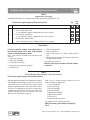
TEST 2
Leakage (reservoir air supply)
For additional information refer to video Assessing Air Brake System Air Leakage (BW2327 - CD)
Full pressure, engine stopped, parking brakes applied
1.
Allow the air pressure to stabilize for at least 1 minute.
2.
Observe the dash gauge pressures for 2 minutes and note any pressure drop.
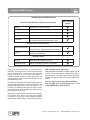
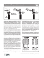
A. Pressure Drop: Single Vehicle
(A 4 psi drop within 2 minutes is allowable for either service reservoir)
B. Pressure Drop: Tractor/Trailer
(A 6 psi drop within 2 minutes is allowable for either service reservoir)
C. Pressure Drop: Tractor/2 Trailers
(An 8 psi drop within 2 minutes is allowable for either service reservoir)
OK
Not
OK
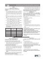
Make all the necessary repairs before proceeding to test 3; see checklist 2 for common corrections.
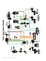
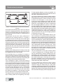
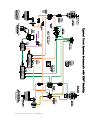
CHECKLIST 2
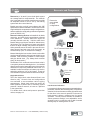
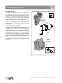
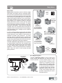
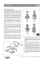
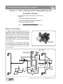
6. Trailer hand control valve
7. Parking control valve
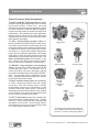
8. System safety valve(s) in the supply reservoir and/or air
dryer
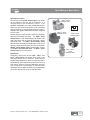
9. Governor (may be mounted on the air dryer as illustrated, on
the compressor, or remotely).
10. Compressor discharge line
If there is excessive leakage in the supply side of
the pneumatic system, one or more of the following
devices could be causing the problem:
NOTE: A leak detector or soap solution will aid in locating the faulty
component.
1.
2.
3.
4.
5.
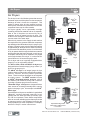
Supply lines and fittings
Low pressure indicator(s)
Service brake relay valve(s)
Spring brake relay valve (where applicable)
Dual brake valve
Retest to verify proper operation of all items repaired
or replaced.
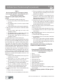
TEST 3
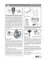
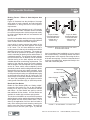
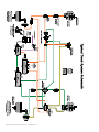
Pressure Modulator Valve and Traction Control Valve Chuff Test
Full pressure, engine stopped, parking brakes released
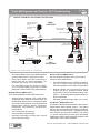
Make and hold brake application. When ignition power is applied,
each modulator solenoid is briefly energized. If the air system is
fully charged and the service brake pedal is depressed during
ignition, the modulator creates a single, sharp audible “chuff” of
air pressure. The modulators are energized in a certain pattern,
as follows: right front, left front, right rear, left rear. This test is
performed only when the vehicle is stationary (if the vehicle
moves the chuff test will not be performed).
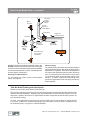
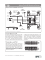
NOTE: The EC-60™ controller will perform a PMV chuff test on all
installed modulators in the following order:
1. Steer Axle Right PMV
2. Steer Axle Left PMV
3. Drive Axle Right PMV
4. Drive Axle Left PMV
5. Additional Axle Right PMV
6. Additional Axle Left PMV
7. Drive Axle TCV
The pattern will then repeat itself.
See appropriate Service Data Sheet for repairs.
Make all necessary repairs before proceeding to
Test 4.
60
More info: visit www.bendix.com
1-800-AIR-BRAKE (1-800-247-2725)