1
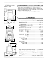
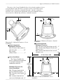
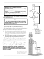
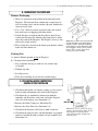
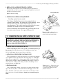
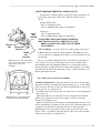
Cottage Franklin Gas Stove
Model 207
CERTIFIED TO AMERICAN NATIONAL STANDARD Z21.88b-2001
AND APPLICABLE PORTIONS OF UL307b
OWNER’S MANUAL
This appliance may be installed in an
aftermarket permanently located,
manufactured (mobile) home, where not
prohibited by local codes.
WARNING: If the information in these
instructions are not followed exactly, a fire or
explosion may result causing property damage,
personal injury or loss of life.
This appliance is only for use with the
type of gas indicated on the rating plate.
This appliance is not convertible for
use with other gases, unless a certified
kit is used.
— Do not store or use gasoline or other flammable
vapors and liquids in the vicinity of this or any
other appliance.
— WHAT TO DO IF YOU SMELL GAS
• Do not try to light any appliance.
• Do not touch any electrical switch; do not use
any phone in your building.
• Immediately call your gas supplier from a
neighbor’s phone. Follow the gas supplier’s
instructions.
• If you cannot reach your gas supplier, call the
fire department.
— Installation and service must be performed
by a qualified installer, service agency or the
gas supplier.
66 Airpark Road, West Lebanon, NH 03784
email: [email protected]
Tel: 800-866-4344
Fax: 603-298-5958
Rev5 (0505)
The installation of the Franklin Gas Fireplace
must conform with local codes, or in the absence
of local codes, with the National Fuel Gas Code,
ANSI Z233.1.
The Cottage Franklin Gas Stove must be
vented with approved “direct-vent” pipe.
Direct-Vent pipe has two concentric
passageways which draw outside air in for
combustion, and let exhaust gasses out.
Installation or replacement of gas piping,
the gas Fireplace, and repair or servicing of
equipment shall be performed only by a
qualified agency. The term “qualified agency”
means any individual, firm, corporation, or
company that either in person or through a
representative is engaged in and is responsible
for (a) installation or replacement of gas
piping or (b) the connection, installation,
repair or servicing of gas utilization equipment,
who is experienced in such work, familiar
with all precautions required, and has complied
with all the requirements of the authority
having jurisdiction.
Installation and repair should be done by
a qualified service person. The appliance
should be inspected before use and at least
annually by a professional service person.
More frequent cleaning may be required due
to excessive lint from carpeting, bedding
material, et cetera. It is imperative that
control compartments, burners and
circulating air passageways of the appliance
be kept clean.
The Cottage Franklin Gas Stove and its main
gas supply valve must be disconnected from the
gas supply piping system during any pressure
testing of that system at test pressures in excess
of 1/2 psi (3.5 kPa).
The Cottage Franklin Gas Stove must be
isolated from the gas supply piping system by
closing its equipment shutoff valve during any
pressure testing of the gas supply piping system
at test pressures equal to or less than 1/2 psi
(3.5 kPa).
An inlet pressure test point is provided on
the gas control valve, immediately upstream of
the gas supply connection to the Fireplace. An
outlet pressure test point is also provided.
The Cottage Franklin Gas Stove, when
installed, must be electrically grounded in
accordance with local codes or, in the absence
of local codes, with the National Electrical
Code, ANSI/NFPA 70.
SAFETY PRECAUTIONS
❏
❏
This appliance is only for use with the type of gas
indicated on the rating plate. This appliance may not
be converted to use with other gasses unless a certified
kit is used.
This appliance is designed to burn either natural gas or
propane. Do not attempt to burn wood, trash, or any
other material in this appliance.
This appliance may not be connected to a chimney
serving a separate solid-fuel burning appliance.
________________________________________________
❏
❏
❏
❏
❏
❏
❏
Due to high temperatures, the appliance should be
located out of traffic and away from furniture and
draperies.
Children and adults should be alerted to the hazards of
high surface temperature and should stay away to
avoid burns or clothing ignition.
Young children should be carefully supervised when
they are in the same room as the appliance.
Clothing or other flammable material should not be
placed on or near the appliance.
The appliance area must be kept clear and free from
combustible materials, gasoline, and other flammable
vapors and liquids.
WARNING: Do not operate appliance with the glass
front removed, cracked or broken. Replacement of the
glass should be done by a licensed or qualified service
person.
The flow of combustion and ventilation air must not be
obstructed.
________________________________________________
❏
❏
❏
❏
❏
Any safety screen or guard removed for servicing an
appliance should be replaced prior to operating the
appliance.
Do not use this appliance if any part has been under
water. Immediately call a qualified service technician to
inspect the appliance and to replace any part of the
control system and gas control which has been under
water.
CAUTION: Label all wires prior to disconnection when
servicing controls. Wiring errors can cause improper
and dangerous operation.
Verify proper operation after servicing.
-------------------------------------------------------------------------------------------------------------------------------------------------------------------------- Table Of Contents
TO THE INSTALLING TECHNICIAN:
QUESTIONS:
First, thank you from all of us at Woodstock Soapstone Co. for installing this
Franklin Fireplace for one of our customers. If you have any questions about
installation, please call us at 800-866-4344. Technical Support will be available
from 9:00AM to 5:00PM Eastern Time, Monday through Saturday. At any other
time, you may leave a message with our answering service with your phone
number and the best time to call, and we will return your call during the next
business day.
800-866-4344
9:00 AM to 5:00 PM
Eastern Time
Monday – Saturday
Please also take the time to go through the Warranty Checklist with the
owner. This will validate the warranty, assure us and the owner that the
installation was performed to local and national codes, and help familiarize the
owner with the safe operation of this gas Fireplace.
Installation must conform to these instructions and local codes
or, in the absence of local codes, with the current National Fuel Gas Code
ANSI Z233.1.
We at Woodstock Soapstone Company are proud to manufacture top
quality hearth products. When you install this Fireplace, we ask that you
maintain our tradition of conscientious effort to make our customers happy
with our product and service.
Sincerely,
WARNING: This unit
must be installed by a
qualified gas technician in
accordance with local codes
or in the absence of local
codes, with the most current
edition of the National Fuel
Gas Code ANSI
Z223.1/NFPA 54.
The Technical Support Staff
Woodstock Soapstone Co., Inc.
TABLE OF CONTENTS
Section
Page
Section
Page
1) Code Approvals..........................................................2
13) Troubleshooting - Installer only............................19
2) Specifications .............................................................2
14) Operating your Gas Fireplace...............................20
3) Tools Needed to Install the Fireplace........................3
15) Lighting Instructions.............................................21
4) Approved Venting/Chimney Materials .....................3
16) Safety Instructions ................................................24
5) Approved Clearances for Inside Locations...............4
17) Remote Control .....................................................25
6) Approved Venting/Chimney Configurations ...........6
18) Lighting the Fire for Remote Control Owners.....27
7) Approved Venting/Chimney Terminal Clearances .12
19) Routine Maintenance ............................................28
8) Unpacking the Cottage Franklin Gas Fireplace......13
20) Annual Inspection .................................................30
9) Pre-Installation Inspection Checklist ......................13
21) Troubleshooting - Owner......................................31
10) Assembling the Cottage Franklin Gas Fireplace ....14
22) Warranty ................................................................33
11) Connecting the Gas Supply/Testing the Flame.......15
Appendix A - Parts List...............................................35
12) Testing Check List and Warranty Registration .......18
Appendix B - Remote Control Installation ................36
-------------------------------------------------------------------------------------------------------------------------------------------------------------------------------------------------------- 1
--------------------------------------------------------------------------------------------------------------------------------------------------------------------------------- Specifications
NOTE: Diagrams include
optional 90° elbow.
1. CODE APPROVALS • Direct Vent • Natural Gas • LPG
The Woodstock Cottage Franklin Gas Stove is listed as a direct vent
appliance. This type of appliance draws all of its air for combustion from
outside of the dwelling through specially designed pipe. It can be used with
natural gas or LPG (liquid propane gas).
Tested to:
American National Standard ANSI Z21.88b-2001
297/8"
231/2"
2. SPECIFICATIONS
For The Woodstock Cottage Franklin Gas Stove:
Fuel .......................................................Liquefied Petroleum Gas (LPG)
..............................................................................Natural Gas (NG)
Manifold Pressure, LPG ...........................................................10.5" w.c.
Manifold Pressure, NG. .............................................................3.5" w.c.
Minimum inlet supply pressure for input
adjustment LPG................................................................11.0" w.c.
Minimum inlet supply pressure for input
adjustment NG ...................................................................4.0" w.c.
Maximum inlet supply pressure LPG......................................20.0" w.c.
Maximum inlet supply pressure NG........................................20.0" w.c.
Input, Btu/Hr
LPG Max. .......................................................22,988
(0 – 2,000 ft.)
Min. .........................................................18,297
NG Max. .......................................................22,552
Min. ........................................................18,691
Output, Btu/Hr LPG Max. .......................................................17,562
Min. ........................................................13,906
NG Max. .......................................................16,515
Min. ........................................................13,644
Orifice size, LPG
Sea level to 5000' ......................................................................#54
5001' or more.......................................................................#55
183/4"
Illustration 2.1 Side View.
173/8"
243/4"
Illustration 2.2 Front View.
91/2"
211/4"
51/2"
243/4"
Illustration 2.3 Top View.
Orifice size: NG
Sea level to 5000'.......................................................................#43
5001' to 7000'.......................................................................#44
7001' or more.......................................................................#45
AFUE: (Annual Fuel Utilization Efficiency)LPG ..........(76% minimum)
AFUE: (Annual Fuel Utilization Efficiency)NG ............(73% minimum)
Glass Panel ..............................................High temperature ceramic glass
Weight, Fireplace only ..................................................................260 lbs.
shipping.............................................................................350 lbs.
Ignition.................................................Standing pilot with Piezo ignition
-------------------------------------------------------------------------------------------------------------------------------------------------------------------------------------------------------- 2
------------------------------------------------------------------------------------------------------------------------------------ Installation Tools and Materials Needed
Hearth: The hearth immediately under the Stove should be constructed of
non-combustible material - ceramic tile (not vinyl), stone, or metal. Protect
carpet or any combustible surface with a hearth that covers an area equal to
the full width and depth of the Stove (243/4" x 211/4") or greater.
A hearth pad of size 36x36 inch is recommended
Clearance to combustible materials
Front of Firebox .............................................................................36"
Sides of Stove...................................................................................8"
Rear of Stove ..................................................................................11"
Rear Corners of Stove ...................................................................4.5"
Rear of 90 Degree Elbow.................................................................2"
3. TOOLS NEEDED TO INSTALL THE FIREPLACE
Multi-meter ( millivolt )
Strap Wrench for Pipe Installation
Manometer
Gas Sniffer
Window Clip Tool
7/16” Socket or Wrench
Glass Cleaner and Towels
Flashlight
Drill/Driver to install screws in first section of vent pipe
5/32” Allen Wrench*
* To install and adjust leveling screws in stove base
4. APPROVED VENTING/CHIMNEY MATERIALS
The venting/chimney system for your Franklin Gas
Stove must be constructed of Simpson Dura-Vent 4” x 65/8”
direct vent gas pipe. All approved direct vent components bring
fresh air into the Stove and vent exhaust gasses at the same time (see
illustration 4.1).
Approved venting materials are available from Simpson
Dura-Vent Dealers or direct from Woodstock Soapstone Company.
Approved components are listed below.
Description
Standard Direct Vent Kit consists of:
2 65/8" x 2' Straight Pipe
1 65/8" x 11" - 14" Adjustable Pipe
2 65/8" x 90 Degree Swivel Elbow
1 65/8" Wall Thimble
1 65/8" Wall Thimble Cover
1 65/8" Horizontal Termination
Dura-Vent No.
Galvanized
Black
904
911
990G
942
940
984
904B
911B
990BG
*
940B
*
AIR IN
EXHAUST OUT
AIR IN
Illustration 4.1 Direct-vent pipe
sends exhaust out and brings air in
at the same time.
* Galvanized Only
-------------------------------------------------------------------------------------------------------------------------------------------------------------------------------------------------------- 3
---------------------------------------------------------------------------------------------------------------------------------Approved Clearances for Inside Locations
Illustration 4.2 All approved
Simpson Dura-Vent Pipe has an
inside passage to vent exhaust
gasses, and an outside passage
used to bring in fresh air for
combustion.
Other Available Pipe:
65/8" x 6" Straight Pipe
65/8" x 9" Straight Pipe
65/8" x 12" Straight Pipe
65/8" x 24" Straight Pipe
65/8" x 36" Straight Pipe
65/8" x 48" Straight Pipe
65/8" x 11"- 14-5/8" Adjustable
65/8" x 17 - 24" Adjustable Pipe
65/8" x 45 Degree Elbow
65/8" x 90 Degree Elbow
65/8" x 90 Degree Adj. Elbow
65/8" x 45 Degree Adj. Elbow
Horizontal Termination Cap
Snorkel Termination Cap
36" Rise
14" Rise
Vinyl Siding Standoff
65/8" Wall Thimble
Wall Thimble Cover
Cathedral Ceiling Support Box
Restrictor Disc (top vent)
Storm Collar
Adj Roof Flashing (0/12-6/12 pitch)
Adj Roof Flashing
(7/12-12/12 steep pitch)
Vertical Termination Cap
Vertical Termination Cap
Vertical Termination Cap
* Galvanized Only
908
907
906
904
903
902
911
917
945
990
990G
945G
984
908B
907B
906B
904B
903B
902B
911B
917B
945B
990B
990BG
945BG
*
981
982
950
942
940
941
929
953
943
*
*
*
*
940B
*
*
*
*
943S
980
991
930
*
*
*
*
5. APPROVED CLEARANCES FOR INSIDE LOCATIONS
WARNING: Due to high temperatures, the Cottage Franklin Gas Stove
should be placed out of traffic and away from furniture, draperies and other
combustibles.
CLEARANCES TO
COMBUSTIBLE
MATERIALS
Front of Firebox ..............36"
Sides of Stove....................8"
Rear of Fireplace .............11"
Rear Corners...................4.5"
Rear of 90 Degree Elbow..2"
The Cottage Franklin Gas Stove is approved for venting in five
configurations:
(1) Up vertically and then elbow through an outside wall with a
maximum horizontal run of 4’.
(2) Straight out the back through an outside wall and into a snorkel
termination cap (maximum 4’ horizontal run, with 1/4” rise per
foot of run).
(3) Up vertically through the roof, with maximum rise of 24’.
WARNING: This unit
must be installed by a
qualified gas technician in
accordance with local codes or
in the absence of local codes,
with the most current edition
of the National Fuel Gas Code
ANSI Z223.1/NFPA 54.
(4) Into an existing fireplace and chimney (maximum height of 24’).
(5) Into an existing masonry or prefabricated metal chimney
(maximum height of 24’).
NOTE: Details for these five configurations start on page 6. Each
installation is unique. Please call a customer service
representative for assistance at 1-800-866-4344.
Clearances inside the house for these three basic installations are
indicated in the illustrations which follow.
-------------------------------------------------------------------------------------------------------------------------------------------------------------------------------------------------------- 4
---------------------------------------------------------------------------------------------------------------------------------Approved Clearances for Inside Locations
The surface of the Cottage Franklin Gas Stove is hot when the appliance is in use.
A safe installation requires that there be adequate clearances between the Cottage
Franklin Gas Stove and nearby combustible materials, so that the combustible
materials are not overheated. The diagrams that follow show minimum clearances
between the Stove, Exhaust Pipe and nearby combustible materials.
2"
4.5"
Min. 11”
10"
4.5"
8"
Illustration 5.1 Minimum Clearances: Corner
Installation
A
Corner Installation
Minimum Clearances
Min. Clearance from corners to
both side walls ......................4.5"
Pipe to wall
(Vertical Vent)..........................2"
Illustration 5.2 Minimum Clearances: Parallel
Installation
B Parallel Installation
Minimum Clearances
Min. Clearance from back of pipe to wall......2"
Min. Clearance from Fireplace to side wall
(Vertical vent)..................................................8"
Min. clearance from back of stove to wall
(Straight vent)...............................................11"
42" Min. Alcove width
C
Alcove Installation
The Cottage Franklin Gas
Stove is approved for installation
in an alcove constructed of
combustible materials.
Minimum Clearances for
Alcove Installation
Min. Clearance from back of
pipe to wall(Vertical Vent).......2"
Min. Clearance from Fireplace to
side walls .................................8"
Min. clearance from back of
stove to wall (Straight vent)...11"
2"
Min. 11”
10"
48"
(1220 mm)
Max
Alcove
Depth
8”
8”
Illustration 5.3 Minimum Clearances: Alcove
Installation
-------------------------------------------------------------------------------------------------------------------------------------------------------------------------------------------------------- 5
--------------------------------------------------------------------------------------------------------------------------------Approved Venting/Chimney Configurations
Combustible Ceiling in Alcove Installation
6" Min.
Minimum Clearances to
Ceilings in Alcove Installation
Min. Clearance from top of pipe
to ceiling/mantle ......................6"
24" Min.
54" Min.
13"
Illustration 5.4 Minimum Clearances to Ceiling in
Alcove Installation
6. APPROVED VENTING/CHIMNEY CONFIGURATIONS
CLEARANCES FOR VENT TERMINAL
Clearances for vent terminal locations are indicated in the diagram and
chart on page 12.
Refer to the manufacturers instructions regarding installation of your
venting system through walls or ceilings. Use only Simpson Dura-Vent GS
Direct-Vent Flue Systems.
The Cottage Franklin Gas Stove is designed to be installed in the
following configurations:
13"
Illustration 6.1
Side wall venting configuration. (Available as
standard vent kit)
13” is the minimum distance rear of the stove can be
from wall when using two 90 deg. elbows as above.
-------------------------------------------------------------------------------------------------------------------------------------------------------------------------------------------------------- 6
--------------------------------------------------------------------------------------------------------------------------------Approved Venting/Chimney Configurations
A. Side Wall Venting
In this venting configuration, the pipe rises directly from the back of the
Stove. The exhaust travels up, through two elbows, and out through a side
wall. See illustration on previous page.
MINIMUM AND MAXIMUM DISTANCES
• Maximum rise ............................................................16 feet
• Maximum recomended run ..........................................4 feet
• Maximum linear distance...........................................20 feet
Note 1. For distance added to horizontal run, an equal
distance must be subtracted from vertical rise. Horizontal
run must not exceed 8'.
Note 2. Each 90 deg. elbow reduces the maximum lineal
distance by 3’. Each additional 45 deg. elbow reduces it by
1.5’
• Wall Opening:
Masonry wall......... ..............................................7" opening
Non-masonry wall.................................framed to 10" x 10"
Refer to Simpson Dura-Vent instruction regarding installation of your
Direct-Vent System.
Please note the following considerations for the location of the vent
terminal:
1. The horizontal run must rise a minimum of 1/4" per foot of run
toward the vent termination.
2. The termination must not be recessed into the the exterior wall or
siding.
3. Clearances must be maintained around the vent termination . See
illustrations on page 12.
4. Vinyl Siding requires protection from vented heat above the
termination. Use Simpson Dura-vent Vinyl Siding Heat Shield Kit,
part #950.
!
P
ALL VENT CLEARANCES MUST BE MAINTAINED.
CHECK YOUR VENT CLEARANCES AGAINST THE
ILLUSTRATIONS ON PAGE 12.
The venting should be located so that people cannot be burned by
accidentally touching hot vent surfaces while the Stove is in operation.
The vent termination must be placed so that it cannot be damaged by
automobile doors, lawnmowers or yard equipment, or falling ice and snow.
-------------------------------------------------------------------------------------------------------------------------------------------------------------------------------------------------------- 7
--------------------------------------------------------------------------------------------------------------------------------Approved Venting/Chimney Configurations
B. Side Wall Venting (straight back through wall)
In this venting configuration, the pipe runs directly out the back of the
Stove, through an outside wall and then up with a snorkel termination cap.
See illustration at left.
4' Max.
11"Min.
Illustration 6.2
If stove is vented straight
back, Snorkel attachment is
required.
MINIMUM AND MAXIMUM DISTANCES
• Maximum run...............................................................4 feet
Note: Use of 45 deg. elbow reduces the max run to 2.5 feet
• Minimum rise...............................................................2 feet
• Minimum Distance between the inside wall and the
back of Fireplace .............................................................11"
• Wall Opening:
Masonry wall .......................................................7" opening
Non-masonry wall.................................framed to 10" x 10"
Refer to the Simpson Dura-Vent instructions regarding installation of
your Direct-Vent system.
Please note the following considerations for the location of the vent
terminal:
1. The horizontal run must rise a minimum of 1/4" per foot of run
toward the vent termination.
2. Clearances must be maintained around the vent termination . See
illustrations on page 12.
3. The termination must not be recessed into the the exterior wall or
siding.
4. Vinyl Siding requires protection from vented heat above the
termination. Use Simpson Dura-vent Vinyl Siding Heat Shield Kit,
part #950.
!
P
ALL VENT CLEARANCES MUST BE MAINTAINED.
CHECK YOUR VENT CLEARANCES AGAINST THE
ILLUSTRATIONS ON PAGE 12.
The venting should be located so that people cannot be burned by
accidentally touching hot vent surfaces while the Stove is in operation.
The vent termination must be placed so that it cannot be damaged by
automobile doors, lawnmowers or yard equipment, or falling ice and snow.
C. Vertical Venting (straight up through roof)
In this venting configuration, the pipe rises directly from Stove and goes
up through the roof, terminating above the roof. See illustration 6.3.
-------------------------------------------------------------------------------------------------------------------------------------------------------------------------------------------------------- 8
--------------------------------------------------------------------------------------------------------------------------------Approved Venting/Chimney Configurations
MINIMUM AND MAXIMUM DISTANCES
• Maximum vertical rise ...................................................24'*
Height of termination above roof must conform to chart
below
Roof Pitch
Flat to 6/12
6/12 to 8/12
8/12 to 10/12
10/12 to 12/12
A Minimum height from roof
to lowest discharge opening
1.0 feet
2.0 feet
3.0 feet
4.0 feet
24' Max.
*Max rise is 24’ without additional elbows
Each 90 deg. elbow reduces the maximum lineal distance by
3’. Each additional 45 deg. elbow reduces it by 1.5’
Refer to the Simpson-Dura Vent instructions regarding installation of
your Direct-Vent system.
!
P
ALL VENT CLEARANCES MUST BE MAINTAINED.
CHECK YOUR VENT CLEARANCES AGAINST THE
ILLUSTRATIONS AT RIGHT, AND PAGE 12.
Illustration 6.3
Vertical venting configuration.
(Max height 24’)
The Cottage Franklin Gas Stove is currently approved only for venting
with the components listed previously on pages 3 and 4. Install the vent
system according to the manufacturers instructions, which are included with
the components.
Lowest
Discharge
Opening
Listed
Cap
Listed
Gas
Vent
A
12"
Roof Pitch is X/12
A Minimum Height
from Roof to Lowest
Discharge Opening
Illustration 6.4
-------------------------------------------------------------------------------------------------------------------------------------------------------------------------------------------------------- 9
----------------------------------------------------------------------------------------------------------------------------------------------------------------------------------------------------- 10
D. Venting Into an Existing Fireplace and Chimney
You can vent your Cottage Franklin Gas Stove into an open
fireplace by running two flexible ducts up the length of the chimney.
One duct will carry the exhaust gases to the top of the chimney while
the other duct brings fresh air into the stove for combustion. See
illustration 6.4.
MINIMUM AND MAXIMUM DISTANCES
• Maximum vertical rise.............................................24 feet*
Venting duct requirements are based on the factors below
• Up to 18’ vertical……. .......................................3” exhaust,
..................................................................3” combustion air
• Up to 24’ vertical……. .......................................3” exhaust,
..................................................................4” combustion air
*Each 90 deg. elbow reduces the maximum lineal distance
by 3’. Each additional 45 deg. elbow reduces it by 1.5’
Refer to the Simpson Dura-Vent instructions regarding installation
of your Direct-Vent system.
!
P
Illustration 6.4 Venting into
fireplace and up into existing
chimney using co-linear ducts.
ALL VENT CLEARANCES MUST BE MAINTAINED.
CHECK YOUR VENT CLEARANCES AGAINST THE
ILLUSTRATIONS ON PAGE 12.
E. Venting Into an Existing Masonry or Prefabricated Metal
Chimney
You can vent your Cottage Franklin Gas Stove into an existing
chimney by running a flexible duct up the length of the chimney.
This 4” duct will carry the exhaust gases to the top of the chimney.
The surrounding chimney area is utilized to bring fresh air into the
stove for combustion.
Venting into a masonry chimney requires a conversion kit, 4”
duct, and a cap. See illustration 6.6 on page 11. Venting into an
existing prefabricated metal chimney requires a conversion kit
specific to the brand of chimney installed, a 4” duct, and a cap. See
illustration 6.5 for more detail.
------------------------------------------------------------------------------------------------------------------------------------------------------------------------------------------------------ 10
----------------------------------------------------------------------------------------------------------------------------------------------------------------------------------------------------- 11
MINIMUM AND MAXIMUM DISTANCES
• Maximum vertical rise ...................................................24'*
• Minimum chimney inside diameter ..................................6”
• Required .............................Existing chimney must be lined
*Max rise is 24’ without additional elbows.
Each 90 deg. elbow reduces the maximum lineal distance by
3’. Each additional 45 deg. elbow reduces it by 1.5’
24' Max.
Refer to the Simpson-Dura Vent instructions regarding installation
of your Direct-Vent system.
!
P
ALL VENT CLEARANCES MUST BE MAINTAINED.
CHECK YOUR VENT CLEARANCES AGAINST THE
ILLUSTRATIONS ON PAGE 12.
MANUFACTURED HOUSING INSTALLATION
The Cottage Franklin Gas Stove may be installed in Manufactured
Housing with the following supplemental requirements:
(1)
The appliance must be securely bolted to the floor with steel
straps secured to the leg bolts and to the floor with minimum
1/4” lag bolts. Contact Woodstock Soapstone Company for
steel straps.
(2)
The appliance must be grounded to the manufactured home
trailer frame with a No. 8 (minimum) solid conductor.
Fig. 6.5 Venting into
existing metal
chimney using 4"
exhaust duct and
conversion kit.
The Cottage Franklin Gas Stove is currently approved only for
venting with the components listed previously on pages 3 and 4.
Install the vent system according to the manufacturers instructions,
which are included with the components.
Note: A manufactured home(USA only) or mobile home OEM
installation must conform with the Manufactured Home
Construction and Safety Standard, Title 24 CFR, Part 3280, or,
when such a standard is not applicable, the Standard for
Manufactured Home Installations, ANSI/NCSBCS A225.1, or
Standard for Gas Equipped Recreational Vehicles and Mobile
Housing, CSA Z240.4
Fig. 6.6 Venting into existing
masonry chimney using 4"
duct and conversion kit.
------------------------------------------------------------------------------------------------------------------------------------------------------------------------------------------------------ 11
--------------------------------------------------------------------------------------------------------------------- Approved Venting/Chimney Terminal Clearances
7. APPROVED VENTING/CHIMNEY TERMINAL CLEARANCES
Roof
Ventilated
Soffit
H
B
Non
Mechanical
Air Supply
D
E
Fixed
Window
EA
C
G
C
Air
Grade
Deck
Illustration 7.1
Roof
F
Nonventilated
Soffit
B
K
Illustration 7.2
J
M
I
L
Mechanical
Air Supply
Vegetation
Public Sidewalk or
Driveway
A. Clearance to a permanently
closed window..................12"
B. Clearance to a window or door
that may be opened ..........12"
C. Clearance above grade. Also,
clearance over deck, porch,
veranda or balcony .............12"
D. Clearance to non-mechanical
air supply inlet or combustion
air inlet of any other
appliance..........................12"
E. Clearance to inside corner or
adjacent wall.....................12"
F. Clearance to a non-ventilated
soffit .................................12"
G. Clearance below deck,
porch, veranda, or balcony
if completely open on two
sides..................................18"
H. Clearance to ventilated soffit
located above the terminal
within a horizontal distance
of 2 feet from the center of the
terminal.............................18"
I. Clearance around a center line
above service regulator.3 feet
J. Clearance to vegetation..3 feet
K. Clearance around a service
regulator vent outlet......6 feet
L. Clearance to a mechanical air
supply............................6 feet
M. Clearance above a paved
sidewalk or driveway on
public property. May not
terminate above a sidewalk
or driveway which is
between two single family
dwellings and serves both
dwellings.......................7 feet
------------------------------------------------------------------------------------------------------------------------------------------------------------------------------------------------------ 12
-------------------------------------------------------------------------------------------------------------------- Pre-Installation Inspection Checklist for Installer
8. UNPACKING THE FIREPLACE
Remove Packaging
1. There is a corrugated carton packed on the front skirt of the
Fireplace. The corrugated box contains the ceramic logset as
well as leveling screws and the window clip tool. Remove the
carton and set it aside.
2. Use a 7/16” socket or wrench to remove bolts and washers
that attach stove to shipping pallet from below.
3. Lift the Fireplace straight up off the pallet by hand, being
careful not to damage the controls and wiring that are under
and at the back of the Fireplace. The Fireplace is heavy. You
will need 2 people to lift it.
4. The ceramic tile is located in the burner pan. Remove rubber
bands and label before use.
Illustration 8.1 There are four bolts that
hold the Fireplace to the pallet during
transport. Before lifting the Fireplace
off the pallet, you must detach the bolts
from the pallet. Remove the four bolts
using a 7/16” wrench. Insert the 4
leveling screws into the base.
Packing List
A. Owners Manual (packed on top of Fireplace)
B. Corrugated box containing:
1. Log set (handle the log set with care; the ceramic logs
are fragile)
2. Window clip tool
3. Leveling screws
4. Three #8 self drilling screws for first section of pipe
9. PRE-INSTALLATION INSPECTION
CHECKLIST FOR INSTALLER
1. Check that both intake and exhaust venting are clear of any
debris or other obstruction at the back of the Fireplace.
2. Check that the gas manifold is connected to both the
controller and the orifice at the back wall of the Fireplace
and is free from damage (see illustration 9.3).
3. Remove the Front Casting (see illustration 9.1).
Gas
Manifold
4. Remove the Glass Front (see illustration 9.2).
5. Check that the Pressure relief Lids are both seated flat
6. Check that the pilot gas tube, and thermocouple are properly
connected to both the pilot assembly and gas controller (see
illustration 9.4)
Illustration 9.1 To remove the front
casting, lift straight up under the lip
that extends over the top of the
glass. This assembly includes the
swinging door.
------------------------------------------------------------------------------------------------------------------------------------------------------------------------------------------------------ 13
------------------------------------------------------------------------------------------------------------------------------------------------------------- Assembling the Fireplace
7. Check that the piezo wire is connected to the pilot assembly.
Push in and turn right gas control knob counterclockwise to
test for spark in the Firebox near the pilot.
CAUTION: Sheet metal edges are sharp. Please handle carefully
Piezo
Thermocouple
Illustration 9.2 The glass front
is held in place by two springloaded clips. To release the
clips, pull and twist.
Gas Pilot Tube
Thermocouple
Connector
Gas Manifold
Log
Illustration 9.3 The burner pan fits
in the base of the Fireplace as
illustrated.
Base
Illustration 9.4 These connections
should be checked carefully.
10. ASSEMBLING THE FIREPLACE
1. INSTALLING THE LOGSET
Your Cottage Franklin Gas Stove has been carefully assembled by
our craftsmen. Because of the fragile nature of the ceramic logset it
is packaged separately to ensure safe shipping, and requires minor
Tile
assembly. Please refer to the following instructions and diagram to
ensure proper placement of the logset.
Remove the front casting by lifting straight up under the lip that
extends over the glass panel. This assembly includes the swinging
door at the bottom and is heavy. Care should be taken while
removing. (See illustration 9.1 on previous page.)
Burner Pan
The glass panel is held in place with two spring loaded clips at the
top and a rail bolted at the bottom. The clips can be released using
the tool provided. Loop the tool over the end of the clips then pull
and twist them out of the way. The panel may be removed by lifting
it up and out. (See illustration 9.2.)
The burner pan is located in the bottom of the firebox and is bolted
in place to ensure safe shipping. The white ceramic tile fits securely
Illustration 10.1 Burner pan with
in the recess in the top side of the burner pan. The top of the tile
ceramic tile and logset assembly.
may protrude above the sides of the burner pan slightly. The logset
Ceramic tile and Logset are
base
should be placed over the ceramic tile. Locate it by sliding it to
fragile. Please handle with care
the right and then back to the left until it hits the metal stop on left of
while installing and cleaning.
the burner pan (See illustration 10.1.). The logset base should be as
far forward as possible.
Place the large log section over the protruding pins at the rear of
the logset base.
------------------------------------------------------------------------------------------------------------------------------------------------------------------------------------------------------ 14
---------------------------------------------------------------------------------------------------------------------- Connecting the Gas Supply & Testing the Flame
2. REPLACE GLASS FRONT/FRONT CASTING
Once the tile and logset have been assembled the glass panel may be
reinstalled. Be sure the bottom edge of panel fits snugly into bottom rail
and clips are fastened securely.
Replace the front casting.
Gas Control Valve
3. INSTALLING OPTIONAL EQUIPMENT:
Installing optional remote control:
The Cottage Franklin Gas stove may be equipped with an
optional remote control. The remote has several functions. It can
turn the burner on or off, regulate flame height or act as a
timer/thermostat. The remote control system includes the remote
transmitter, the remote receiver, and connecting wires.
Remote Receiver
Refer to instructions for installation and operation included with
the remote control system. (See appendix B page 36)
Illustration 10.2 Optional remote
control system connections to
control valve and switch diode.
11. CONNECTING THE GAS SUPPLY & TESTING THE FLAME
WARNING: This unit must be installed by a qualified gas
technician in accordance with local codes or in the absence of
local codes, with the most current edition of the National
Fuel Gas Code ANSI Z223.1/NFPA 54.
1. CHECK THE GAS LINE PRESSURE (LP)
Before connecting the Stove to the gas line, you should check the gas
line pressure. If the gas line pressure is too high (greater than .5 psi,
14"wc) it will rupture the gas control valve on the Stove.
2. ATTACH GAS LINE TO THE CONTROL VALVE
The gas supply line is connected to the Stove gas control valve through
a 1/2" flexible connector pre-attached to the valve using a 3/8" male NPT
fitting. The gas supply line for either propane (LPG) or natural gas (NG)
should be large enough to support (25,000 Btu) and should be connected
with a male 1/2" 45 degree flare fitting. Consult local building codes to
properly size the gas supply line.
3. TEST FOR LEAKS
Test for leaks using a sniffer, soapy water or an approved leak testing
spray. Check each joint or connection from the main supply valve to the
Stove. Check the connections on the control valve as well as those in the
Stove in case one loosened in shipment. Again, never test with an open
flame.
Illustration 11.1 Connection to the
stove can be made with a straight
or elbowed 1/2" fitting into the
flexible connector.
------------------------------------------------------------------------------------------------------------------------------------------------------------------------------------------------------ 15
---------------------------------------------------------------------------------------------------------------------- Connecting the Gas Supply & Testing the Flame
4. TEST PRESSURE THROUGH CONTROL VALUE
Test pressure to and through the control valve using a manometer on
the test gauge taps on the control valve. The line must be tested as
follows:
Propane (LPG or LP):
10.5" w.c.manifold pressure
11.0" w.c.minimum inlet supply for adjustment
Burner
Gas
Manifold
Pilot Gas
Tube
Thermocouple
Connector
Flexible
Gas
Connector
Illustration 11.2 This illustration
shows connection at the control
valve at the rear of the
Fireplace.
Natural gas:
3.5" w.c.manifold pressure
4.0" w.c.minimum inlet supply for adjustment
5. LIGHT THE STOVE, FOLLOWING LIGHTING
DIRECTIONS ON PAGE 21. (FRONT GLASS AND
FRONT CASTING MUST BE IN PLACE PRIOR
TO LIGHTING)
6. The Air Shutter covers the end of the venturi opening at the base of
the Burner Pan and controls the air/fuel mixture. The Shutter has been
pre-set to provide an optimum yellow flame at sea level when the Logset
is warmed up.
If you are operating a Natural Gas Stove at an elevation other than sea
level, it may be necessary to adjust the position of the air shutter. Wait
fifteen minutes after first lighting the Burner to see if the flame changes
from mostly blue to bright yellow. If it remains blue than there is too much
air getting into the mix. If the flame turns orange or smoky then there is too
little air getting into the mix.
Note: Allow Stove to cool before handling.
Illustration 11.3 The burner pan
is attached as illustrated above.
Air Shutter Adjustment To adjust the amount of air, remove front casting,
glass panel and logset assembly following instructions on p. 14. The burner
pan is secured to the firebox with a one inch bolt which must be removed to
take the pan out. (see diagram 11.3)
Carefully lift the burner pan up and out of the firebox, avoid damaging the
orifice at the rear.
Adjust the shutter by loosening the screw (see diagram 11.5). Twist the
shutter open to allow more air into the venturi or closed to restrict the
amount of air. Tighten screw.
Replace the burner pan by inserting the venturi under the back edge of the
firebox and pushing it carefully over the orifice. Note: When the burner pan
is properly located it will sit squarely in the firebox with equal space
approximately 1/8" between the four tabs on the pan and the sides of the
firebox. The 1" bolt will fit easily into the tab at the front of the pan when
in the proper position. (see diagram 11.4)
------------------------------------------------------------------------------------------------------------------------------------------------------------------------------------------------------ 16