1
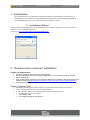
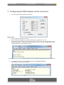
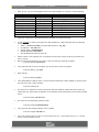
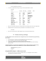
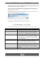
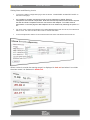
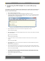
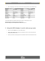
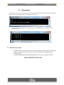
Quick Start Guide Serial to WiFi Adapter Quick Start Guide Serial to WiFi Adapter www.wifiandscales.com 1 Introduction This guide will help you install and configure the Serial to WiFi Adapter for first time use. It describes how to configure the required WiFi and IP parameters via a serial port terminal on your computer before it can be connected to a serial port of a scale. 1.1 Installation Wizard For easy install and configuration you can download our Installation Wizard and connect the WiFi Adapter to your computers serial port Download: http://jws.hd-wireless.se/wifiScaleWizard.jnlp 2 Requirements serial port installation Things you need to have: The WiFi Scales Serial to WiFi 802.11b+g adapter External AC adapter with 9V DC output voltage and a 2.5 mm coaxial connector, positive sleeve negative tip. A PC or MAC with a serial port or an external USB-Serial Port adapter. We recommend to use ATEN UC 232A (http://www.vetek.com/USB-converter-unit-with-cable-for-VB2-mm/article ) A terminal program like Windows HyperTerminal, TeraTerm or similar. Things you need to know: The SSID (the name) of the WiFi Network you want the Serial Adapter to connect to. Type of security and security key of the WiFi Network To set a static IP address for the Serial WiFi adapter you need to know: IP address to use for the adapter The network mask The default gateway for the network Quick Start Guide Serial to WiFi Adapter www.wifiandscales.com 3 Configuring the WiFi adapter via the serial port The serial port settings should be as follows: How to do it: Start a serial port terminal on the PC Connect the WiFi Adapter to the Serial Port/Serial port adapter on the PC Insert the DC plug to power the unit and hit “Return” within 3 sek. You should read “Entering configuration mode” on the terminal and a $ prompt. If you are to late in hitting “Return” the terminal will print a lot of illegible symbols. Example of terminal printout, too late at top row and in time with the entering shown in row below. The adapter contains a small database with all user settable parameters. The following commands are available Quick Start Guide Serial to WiFi Adapter www.wifiandscales.com With “db set” you can set all parameters for the WiFi Adapter to connect to a WiFi Network Parameter SSID Type of key used WEP, WPA/WPA2 key Possible Values String none, wep, wpa String Command db set /wl/ssid db set /wl/key_type db set /wl/key IP address Default Gateway Netmask IPv4 address IPv4 address IPv4 address db set /net/ip <ip> db set /net/gw <gw> db set /net/mask <mask> Enable DHCP Boolean db set /net/dhcp <0 or 1> Typing an erroneous command will list the available command as a help In this example we want to configure the WiFi Adapter for a WiFi Network with the following characteristics SSID = my-wifi-net, Wpa encrypted with pass key ”my_key” IP address = 192.168.2.10 Subnet mask = 255.255.255.0 Default Gateway 192.168.2.1 We will disable the DHCP client “0” Please note the new settings are not entered into the flash memory until the command “db store” is given. We can set the parameters in any order, here we start with entering the SSID $ db set /wl/ssid my-wifi-net Then we enter the security encryption type in this case we are using WPA $ db set /wl/key_type wpa Enter the key $ db set /wl/key my-key Then we disable the DHCP client. To know what IP address the WiFi Adapter is going to have we want it to have a static address. $ db set /net/dhcp 0 We enter the IP address we have selected for the WiFi Adapter. Make sure that is does not collide with any other static set address or the address range managed by the networks DHCP server. $ db set /net/ip 192.168.2.10 We enter the corresponding network mask. $ db set /net/mask 255.255.255.0 Then we enter the default gateway of the network $ db set /net/gw 192.168.2.1 If the unit is still in factory preset i.e. if the value is set to “1” we need to set it to “0” o set the unit to normal operation mode Quick Start Guide Serial to WiFi Adapter www.wifiandscales.com $ db set /app/factory_preset 0 To check our parameters we type “db get” to list all parameters to check. $ db get PATH ---------------------------/wl/ssid /wl/key /net/dhcp /net/ip /net/mask /net/gw /proxy/mode /proxy/baudrate /proxy/ip /proxy/port /app/mode /app/factory_preset /wl/key_type /app/name /app/debug FLAGS SZ TYPE VALUE(S) INFO ----------- -- ----- -------------- ---------NV 1 SSID my-wifi-net NV 1 STR my-key NV 1 BOOL 0 NV 1 IP 192.168.2.10 NV 1 IP 255.255.255.0 NV 1 IP 192.168.2.1 NV 1 BOOL client(0) NV 1 U32 9600 NV 1 IP 0.0.0.0 NV 1 U16 2000 NV 1 BOOL http(0) NV 1 BOOL 0 NV 1 U8 wpa(2) NV 1 STR NV 1 BOOL 0 Note: the actual list is longer as it includes alarm and warning levels which are omitted here. Satisfied with the result we enter the parameters into the flash with ”db store” $ db store We can now disconnect the WiFi Adapter from the serial port and DC power. 3.1 Restore factory settings The WiFi Adapter can be returned to the configuration pre-set in manufacturing by following these steps: The reset button is located in the hole between the LEDs and DC jack. Use a toothpick or another pin that fits the hole snugly. Insert the pin straight into the hole and press the button for 5 sec. The red and green led starts blinking simultaneously indicating that the unit is in factory settings mode. If the WiFi Adapter is in serial port configuration mode it is NOT possible to restore factory settings with the reset button, the command line is used instead as shown below: $ db set /app/factory_preset 1 $ db store $ reset Using the WiFi Adapter in Web server mode The scale has to have the “Serial Port Mode” set to “0” = full duplex. How to do this is described in the manual for the scale. Quick Start Guide Serial to WiFi Adapter www.wifiandscales.com Turn the scale off before you plug in the adapter to the serial port. Fasten the adapter with the screws assure a good connection. If the adapter is plugged in with the power on, the scale can indicate battery low when the adapter is connected. For a scale that does not provide adapter power via the d-sub interface an external AC-DC adapter has to be used. This should be a 9V AC-adapter with minus on the centre pin. The same type used by the scales. Start a web browser at a PC connected to the same network as the WiFi Adapter and type in the address for the WiFi Adapter in the address field. The webpage for the WiFi Adapter and the Scale comes up shortly. 3.2 The WiFi Adapter scale web GUI The following commands can be invoked via the web page. By clicking on the buttons Web page key UPDATE TARE ZERO AUTO REFRESH ON/OFF GR (if shown) NT (if shown) Configure Alarm Settings Action This command will update the scale reading. The indicator will show ERR if the scale is in motion or inaccessible. This command is sent to the indicator to tare the scale. The indicator will not respond if the scale is in motion, positive overload or negative overload. The indicator will also not respond if it is displaying a negative gross value. This command is sent to zero the scale. The indicator will not respond if the scale is in motion, positive overload or negative overload. The indicator will also not respond if it is not in gross mode or within the zero range specified in F4 of the Setup Menu. Toggles the automatic refresh of the web page on or off. This command is sent to the indicator to revert to gross mode. The indicator will not respond if the scale is in motion, positive overload or negative overload. The indicator will also not respond if it is not in net mode. This command is sent to the indicator to revert to net. The indicator will not respond if the scale is in motion, positive overload or negative overload. The indicator will also not respond if it is not in gross mode or a tare has yet to be established. Opens the Alarm configuration page Quick Start Guide Serial to WiFi Adapter www.wifiandscales.com Setting Alarm and Warning Levels To get to the Alarm configuration page click the button “CONFIGURE ALARM SETTINGS” on the main scale page. It is possible to set alarm and warning levels for three parameters. Weight, External Temperature and Internal Temperature. Note that external temperature measurement requires the WiFi and Scale Temperature Sensor connected to WiFi Adapter. To include external temperature on the web page the WiFi Adapter has to be restarted by switching the power on / off For each of the measured parameters four alarm/warning trig levels can be set, First Alert and Alarm Level. Tick the box above the levels to activate the alarm. In the example below alarms for all measurements has been activated and all levels set. When a value is outside the warning range it is displayed in dark red and when it is outside the alarm range it is displayed in bright red. Quick Start Guide Serial to WiFi Adapter www.wifiandscales.com 4 Configuring the WiFi Adapter for serial cable proxy mode It is possible to use two WiFi Adapters as a replacement for a serial cable by connecting one at the scale and the other to a PC or another device that the scale usually communicates with over a serial RS232 cable. Start a serial port terminal on the PC Connect the WiFi Adapter to the Serial Port/Serial port adapter on the PC Insert the DC plug to power the unit and hit “Return” within 3 sek. You should read “Entering configuration mode” on the terminal and a $ prompt. If you are to late in hitting “Return” the terminal will print a lot of illegible symbols. Example of terminal printout, to late at top row and in time a the second row Set the application mode to proxy with the db set /app/mode command $ db set /app/mode proxy Set client mode to one of the WiFi Adapter and the other in server mode. With the command db set /proxy/mode $ db set /proxy/mode client or $ db set /proxy/mode server Set the port number to be used should be the same on both client and server. (2000 is default) $ db set /proxy/port 2000 For the WiFi Adapter acting as client set the IP address for the WiFi Adapter acting servers with /proxy/ip. $ db set /proxy/ip 192.168.1.71 Set the appropriate baud rate. The scale can use 1200, 2400, 4800 or 9600. Different baud rate can be set for the server WiFi Adapter and client WiFi Adapter. The default value is 9600. $ db set /proxy/baudrate 9600 If access point ssid and IP address for the unit has not been configured this is done in the same way as for in the web server mode with the commands, db set /wl/ssid, db set /net/IP, db set /net/gw and db set /net/mask. At last store the edited data with “db store” $ db store Quick Start Guide Serial to WiFi Adapter www.wifiandscales.com After configuring the two units you should have settings similar to the example below. PC <--> NRE801/1 /wl/ssid vetek_demo /wl/key /net/dhcp 0 /net/ip 192.168.0.70 /net/mask 255.255.255.0 /net/gw 0.0.0.0 /proxy/mode client /proxy/baudrate 57600 /proxy/ip 192.168.0.71 /proxy/port 2000 /app/mode proxy NRE801/2 <--> SCALE /wl/ssid vetek_demo /wl/key /net/dhcp 0 /net/ip 192.168.0.71 /net/mask 255.255.255.0 /net/gw 0.0.0.0 /proxy/mode server /proxy/baudrate 9600 /proxy/ip 0.0.0.0 /proxy/port 2000 /app/mode proxy In the serial cable proxy mode the client end can also be a telnet client of a PC. Start telnet with the command >telnet IP-address port With the settings from the example above >telnet 192.168.0.71 5 Using the WiFi Adapter in serial cable proxy mode Plug in the WiFi Adapter to the scale’s RS-232 port. Plug the WiFi Adapter set to client into a serial port of a PC or other device that can communicate with the scale. Power up both units, shortly they will be connected to the wlan and found each other. Quick Start Guide Serial to WiFi Adapter www.wifiandscales.com 5.1 Using telnet Start a telnet client on a PC connected to the same WiFi network as the Serial Cable Proxy Server with the servers IP-address and the configured port number. The scale is now accessible and can receive the commands listed in the scale manual (P,T,Z,G N or C) 6 Known Issues If WEP is used and the wrong key is entered the green LED will light up when the adapter is associated with the AP even though no traffic is possible due the erroneous key. In telnet mode does some terminal hide the minus sign for negative values. www.wifiandscales.com