1
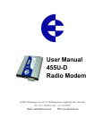
Technical Manual 1.05, C600 Professional
Technical Manual
M2M Control C600 Professional
Version 1.05
Technical Manual 1.05, C600 Professional
Introduction
This manual contains technical documentation allowing easy installation and use of the
C600 Professional unit. For information on the programming and software configuration of
the C600 Professional please refer to the M2M Control IDE (Integrated Development
Environment) documentation.
The C600 Professional is the first member belonging to the new M2M Control C-Series
generation of powerful M2M units. The unit has an impressive list of features including full
support for GPRS, SMS, Voice/DTMF and Data calls. The unit is especially suited for
mobile tracking applications with its onboard GPS-receiver and advanced power
management features. The unit is fully supported by the M2M Control IDE development
tool and is fully backward compatible with previous generation of C600 units.
The C600 Professional includes many sophisticated features, including a CAN-bus
interface for connection to vehicle bus networks, a SD-CARD reader with a FAT
compatible file-system for easy sharing of files with a PC. There is optional support for
Bluetooth, Ethernet, WiFi, Camera module and a Mobile Data Terminal.
The advanced power-management features on the C600 Professional combined with the
on-board high-capacity Li-Ion battery allows the unit to stay in power-saving modes for a
longer period of time still being connected to the GSM network and capable of waking up
on for example GSM activity, change of digital inputs or a vibration sensor!
These features open up for the use of the C600 Professional in exciting new application
areas where extremely low power consumption and flexible wake-up conditions are a
crucial parameter for successful product integration.
Attention: the use of GSM and GPRS services can generate cost. Take care that the
tariff of the used SIM card is suitable for your application. We highly recommend not using
SIM cards where GPRS services are charged by elapsed time.
Page 2 of 24
M2M Control
by Infranet Technologies GmbH
Tempowerkring 2
21079 Hamburg
Germany
Ph: +49.40.69647-260
Fax: +49.40.69647-259
Email: [email protected]
Web: www.m2mcontrol.de
Technical Manual 1.05, C600 Professional
Table of Contents
Introduction ..........................................................................................................................2
Table of Contents ................................................................................................................3
Graphical view .....................................................................................................................4
External connections ...........................................................................................................5
Overview ..........................................................................................................................5
Power supply....................................................................................................................8
Digital outputs ..................................................................................................................9
Digital Inputs / Ignition Input .............................................................................................9
Analog Inputs .................................................................................................................11
Serial port 1 / programming port / RS485 port................................................................11
Serial port 2....................................................................................................................12
CAN................................................................................................................................13
1-Wire.............................................................................................................................14
DC-Out ...........................................................................................................................14
Headset connector .........................................................................................................15
Installing the SIM-card .......................................................................................................16
Installing the SD-CARD .....................................................................................................17
Connecting GSM and GPS antennas ................................................................................17
GSM Antenna.................................................................................................................17
GPS Antenna .................................................................................................................17
Indicators (LED’s) ..............................................................................................................18
Switches ............................................................................................................................19
DIP-Switch .....................................................................................................................19
Reset-Switch ..................................................................................................................19
Internal Li-Ion battery .........................................................................................................20
Vibration Sensor ................................................................................................................20
Specifications for the C600 Professional ...........................................................................21
Specifications for the 16-channel GPS receiver.................................................................22
Appendix A – Enabling the CAN bus Write capability ........................................................23
Page 3 of 24
M2M Control
by Infranet Technologies GmbH
Tempowerkring 2
21079 Hamburg
Germany
Ph: +49.40.69647-260
Fax: +49.40.69647-259
Email: [email protected]
Web: www.m2mcontrol.de
Technical Manual 1.05, C600 Professional
Graphical view
Page 4 of 24
M2M Control
by Infranet Technologies GmbH
Tempowerkring 2
21079 Hamburg
Germany
Ph: +49.40.69647-260
Fax: +49.40.69647-259
Email: [email protected]
Web: www.m2mcontrol.de
Technical Manual 1.05, C600 Professional
External connections
Overview
Connections to external equipment are done via the connectors located back and forth on
the product. All connections are available externally for easy access; this also includes
SIM-Card and SD-Card. There are no user-serviceable parts inside and the warranty is
void if the unit is disassembled.
The front plate is equipped with connectors commonly accessed by the user (SIM-Card,
SD-CARD, DIP-Switch, Headset, LED’s and RS232). The back plate holds all connectors
necessary for installation (4-pin for Power and ignition, 6-pin for RS232/Programming, 12pin for different serial interfaces and a 16-pin for digital I/O + analog inputs). Connection to
Quad-band GSM antenna is via a SMA Female and connection to a 3V active GPS
antenna is done via the SMB Male connector. Both antenna connectors are located on the
back plate. A graphical overview of the front- and back plate is shown below:
System
LED 1+2 LED 1+2
Pin 1
Headset
Connector
Sim Card Reader
Serial Port 2
LED 3+4
SD-CARD Reader
Dipswitch
System
LED 3
1
System Switch
Front-side view
GPS
antenna
GSM
antenna
X3: I/O
9
1
1
4
X4: Serial Port 1 /
Service port
1
3
1
7
X2: Communication
X1: Power
Back-side view
Page 5 of 24
M2M Control
by Infranet Technologies GmbH
Tempowerkring 2
21079 Hamburg
Germany
Ph: +49.40.69647-260
Fax: +49.40.69647-259
Email: [email protected]
Web: www.m2mcontrol.de
Technical Manual 1.05, C600 Professional
Connector X1: 4 pin (Power) connector overview.
Pin
Name
Description
1
SUPP
Power supply, positive (+) connection
2
DI5/IGN
Digital input 5 / Ignition input (Shared with 16 pin connector)
3
SUPP
Power supply, positive (+) connection
4
PGND
Power Ground
Connector X2: 12 pin (Communication) connector overview.
Pin
Name
Description
1
1Wire
1-Wire bus for ID-Button / Temperature sensor
2
SGND
Signal Ground
3
CAN-H
CAN-bus H-signal
4
Voice
External voice
5
RS485A
RS485 A* signal
6
RS485B
RS485 B* signal
7
1W-LED
1-Wire ID-Button LED
8
SGND
Signal Ground
9
CAN-L
CAN-bus L-signal
10
SGND
Signal Ground
11
SGND
Signal Ground
12
DC-Out
+3.3V/150mA DC-Out for external equipment. (Shared with 6 pin
connector)
*Signals are inversed compared to EIA standard.
Connector X3: 16 pin (I/O) connector overview.
Pin
Name
Description
1
DOUT 1
Digital output 1
2
DOUT 3
Digital output 3
3
DIN 1
Digital input 1
4
SGND
Signal Ground
5
DIN 3
Digital input 3
6
DIN 5/IGN Digital input 5 / Ignition input (Shared with 4 pin connector)
7
AIN 1
Analog input 1
8
AIN 2
Analog input 2
9
DOUT 2
Digital output 2
10
DOUT 4
Digital output 4
11
DIN 2
Digital input 2
12
SGND
Signal Ground
13
DIN 4
Digital input 4
14
SGND
Signal Ground
15
AGND
Analog Ground
16
AGND
Analog Ground
Page 6 of 24
M2M Control
by Infranet Technologies GmbH
Tempowerkring 2
21079 Hamburg
Germany
Ph: +49.40.69647-260
Fax: +49.40.69647-259
Email: [email protected]
Web: www.m2mcontrol.de
Technical Manual 1.05, C600 Professional
Connector X4: 6 pin (Serial port 1 / programming) connector overview.
Pin
Name
Description
1
TD
RS232 transmit data from Serial port 1
2
RS-Detect Programming cable detect, normally unconnected (if programming
cable, connect to GND)
3
DC-Out
+3.3V/150mA DC-Out for external equipment. (Shared with 12 pin
connector)
4
RD
RS232 receive data to Serial port 1
5
SGND
Signal Ground
6
SGND
Signal Ground
RJ45 (Serial port 2) connector overview.
Pin
Name
Description
1
DSR
Data Set Ready
2
DCD
Data Carrier Detect
3
DTR
Data Terminal Ready
4
SGND
Signal Ground
5
RD
Receive data to Serial port 2
6
TD
Transmit data from Serial port 2
7
CTS
Clear To Send
8
RTS
Request To Send
Accessories available from M2M Control for cable assembly.
Order-code
Name
RT-O-TYCO-H4
TYCO, Connector house 4 pins. Bag with 10 pcs
TYCO p/n: 794617-4
RT-O-TYCO-H6
TYCO, Connector house 6 pins. Bag with 10 pcs
TYCO p/n: 794617-6
RT-O-TYCO-H12
TYCO, Connector house 12 pins. Bag with 10 pcs
TYCO p/n: 1-794617-2
RT-O-TYCO-H16
TYCO, Connector house 16 pins. Bag with 10 pcs
TYCO p/n: 1-794617-6
RT-O-TYCO-CR
TYCO p/n: 794606-1
RT-O-TYCO-TOOL
TYCO p/n: 91501-1
Alternative tools:
TYCO, Crimp Contacts for connector house. Wire size 0.2 to 0.5
mm2. Bag with 100 pcs.
TYCO, Crimp hand tool for easy assembly of TYCO crimp contacts.
Wire size 0.2 to 0.5 mm2
Tyco 91501-1 (0.20 to 0.50mm2) RS 495-9675, Farnell 1111475
Tyco 91502-1 (0.05 to 0.15mm2) RS 495-9675, Farnell 1111476
Molex 69008-0982 (0.20 to 0.50mm2) RS 233-3059, Farnell 673122
Molex 69008-0983 (0.05 to 0.05mm2) RS 233-3065, Farnell 673134
Tyco 843996-6 extraction tool. RS 495-9704, Farnell 1111477
2.5mm MicroJack
Plug for headset connector. Farnell 5096339 (black plastic house) or
Farnell 8045453 (metal house).
Page 7 of 24
M2M Control
by Infranet Technologies GmbH
Tempowerkring 2
21079 Hamburg
Germany
Ph: +49.40.69647-260
Fax: +49.40.69647-259
Email: [email protected]
Web: www.m2mcontrol.de
Technical Manual 1.05, C600 Professional
Power supply
The C600 Professional unit is to be supplied with 8..36 VDC from an external DC power
source connected to the 4 pin power connector. Positive power is applied to the SUPP pin
and ground is connected to the PGND pin.
The connector has two “SUPP” supply pins as these also supplies power for the Digital
Outputs. If the total current consumption on the digital outputs exceeds 1.5A then power
must be applied to both pins. Otherwise one pin would be sufficient.
There are three different labels for the ground connections: Power Ground (PGND), Signal
Ground (SGND) and Analog Ground (AGND). The signal and analog grounds are filtered
from the power ground. Power ground must only be used as power supply return path. The
signal ground is used as ground reference for digital I/O’s and serial interfaces. And the
analog ground is used as a low noise analog ground reference for the analog inputs.
The C600 is protected against wrong polarity. However if the C600 unit is installed with
ground connected to the C600 unit chassis (for example mounted with screws on the
vehicle chassis) a wrong polarity will destroy the internal GND connection. It is therefore
recommended to install a fuse on the positive supply for protection.
The C600 also contains an internal high capacity backup battery, which will supply the
C600 if the external power supply should fail or be disconnected. By default the C600 is
powered down when a power fail occur. This setting however can be changed. Please
consult the M2M Control IDE online help for more information.
When the ignition input is activated with a logical high, the C600 unit will wake-up if it was
in power down mode. The ignition input (digital input 5) is available on the power
connector to minimize the need for connectors in minimal connector installations, but it is
also available on the 16 pin connector (digital I/O and analog Inputs) - only one should be
used at a time.
X1: 4 pin (Power) connector overview.
Pin
Name
Description
1
SUPP
Power supply, positive (+) connection
2
DI5/IGN
Digital input 5 / Ignition input (Shared with 16 pin connector)
3
SUPP
Power supply, positive (+) connection
4
PGND
Power Ground
Page 8 of 24
M2M Control
by Infranet Technologies GmbH
Tempowerkring 2
21079 Hamburg
Germany
Ph: +49.40.69647-260
Fax: +49.40.69647-259
Email: [email protected]
Web: www.m2mcontrol.de
Technical Manual 1.05, C600 Professional
Digital outputs
The digital outputs control four “high-side” switches. They function like a contact, where
one side is connected to the positive supply of the C600 unit, and the other is the output.
The switches are protected against short circuit, ESD and electronic kickback from
inductive loads such as relays etc. The maximum switch-able inductance is 20mH and
must not be exceeded.
The digital outputs are supplied through the 4 pin power connector, which also supplies
the rest of the C600 unit. As described previously there are two dedicated power pins on
this connector. If the total current consumption on the digital outputs exceeds 1.5A then
power must be applied to both pins. Otherwise one pin would be sufficient.
As the power is supplied together with the C600 main power, a powerfail would also
impact the digital outputs.
The C600 unit offers a very advanced power management, which makes it possible to
have one or more outputs enabled while the C600 is in low power mode. Please consult
the M2M Control IDE online help for more information.
X3: 16 pin (I/O) connector overview.
Pin
Name
Description
1
DOUT 1
Digital output 1
9
DOUT 2
Digital output 2
2
DOUT 3
Digital output 3
10
DOUT 4
Digital output 4
Digital Inputs / Ignition Input
The digital inputs are all low-pass filtered and transient protected. To activate the inputs,
connect a positive voltage between the input and the GND connector.
Please note: The DIN 5/IGN input is a special input as it also functions as the ignition
input. If the ignition input is activated with a logical high or low (Wait For Event mode only)
when the C600 is in low power mode, it will wake-up the unit. A power apply will also
wake-up the unit if it is in power-down mode or WaitForEvent mode with power Apply
and/or ignition selected for wake-up. The ignition is debounced with a period between 1-2
ms when used as a digital input. So any logical level applied to this input must be greater
than 2 ms to be valid. The DIN 5/IGN input is available on both the 4 pin power connector
and the16 pin connector together with the other digital inputs – only one should be used at
a time.
The power management allows the possibility to configure a wake-up on one or more
digital inputs with individually configured falling- or rising edge detection. Please consult
the M2M Control IDE online help for more information.
Page 9 of 24
M2M Control
by Infranet Technologies GmbH
Tempowerkring 2
21079 Hamburg
Germany
Ph: +49.40.69647-260
Fax: +49.40.69647-259
Email: [email protected]
Web: www.m2mcontrol.de
Technical Manual 1.05, C600 Professional
X3: 16 pin (I/O) connector overview.
Pin
Name
Description
3
DIN 1
Digital input 1
11
DIN 2
Digital input 2
5
DIN 3
Digital input 3
13
DIN 4
Digital input 4
6
DIN 5/IGN Digital input 5 / Ignition input. (Shared with 4 pin connector)
4
SGND
Signal Ground
10
SGND
Signal Ground
14
SGND
Signal Ground
Page 10 of 24
M2M Control
by Infranet Technologies GmbH
Tempowerkring 2
21079 Hamburg
Germany
Ph: +49.40.69647-260
Fax: +49.40.69647-259
Email: [email protected]
Web: www.m2mcontrol.de
Technical Manual 1.05, C600 Professional
Analog Inputs
The analog inputs are voltage inputs with a range from 0V to 10V DC. The analog voltage
is converted to a digital value with a resolution of 10bit or 1024 in decimal. The decimal
value with 10V applied to the input is 1023 and 512 for 5V.
The input signal is connected between AIN and AGND. AGND must be connected to the
reference of the connected equipment. Please be aware that deviations may occur, as the
system is very noise sensitive. Avoid long unshielded wires and large fast-changing
signals routed parallel to the analog signals.
The inputs are low-pass filtered, ESD- and transient protected.
X3: 16 pin (I/O) connector overview.
Pin
Name
Description
7
AIN 1
Analog input 1
8
AIN 2
Analog input 2
15
AGND
Analog Ground
16
AGND
Analog Ground
Serial port 1 / programming port / RS485 port.
This port can be used as general-purpose RS232 serial port or as a programming port. In
order to use the port for programming, the RS-DET pin must be connected to GND. When
using the port as general-purpose RS232, the RSDET pin must be left unconnected.
Further details on the programming cable are available in the M2M Control IDE online
help.
This serial port is shared with the RS485 communication port available on the 12 pin
connector. If the RS485 port is used it is not possible to use the RS232 port, and vice
versa. If however, a programming cable is inserted the RS485 communication is disabled
automatically.
The RS485 is a multi-drop network with a maximum of 32 units connected simultaneously
to the bus. The RS485 bus contains the A (positive) and B (negative) signals, as well as a
signal ground, which always must be connected to the common signal ground for all units
connected to the RS485 bus! The maximum cable length for the RS485 bus is approx 400
meters, however this limit can be influenced by the quality of the cable, signaling rate,
noise etc. At longer cable lengths, noisy environments or high communication speed it
might be necessary to terminate the transmission line with a 120 ohm resistor between
RS485A and RS485B at each end of the wires to avoid signal reflections etc.
Be aware that it is much confusion about the pin labeling of RS485. The above-mentioned
conditions for positive and negative signals are actually the inverse of the standard
released by EIA.
Page 11 of 24
M2M Control
by Infranet Technologies GmbH
Tempowerkring 2
21079 Hamburg
Germany
Ph: +49.40.69647-260
Fax: +49.40.69647-259
Email: [email protected]
Web: www.m2mcontrol.de
Technical Manual 1.05, C600 Professional
X4: 6 pin (Serial port 1 / programming) connector overview.
Pin
Name
Description
1
TD
RS232 transmit data from Serial port 1
4
RD
RS232 receive data to Serial port 1
2
RS-Detect Programming cable detect, normally unconnected (if programming
cable, connect to GND)
5
SGND
Signal Ground
X2: 12 pin (Communication) connector overview.
Pin
Name
Description
5
RS485A
RS485 A* signal
6
RS485B
RS485 B* signal
11
SGND
Signal Ground
*Signals are inversed compared to EIA standard.
Serial port 2
The serial port 2 is a general-purpose RS232 port with all control signals according to EIA561 that defines RS-232 on a modular connector.
The signals are available on the RJ45 connector located on the front plate of the C600.
RJ45 (Serial port 2) connector overview.
Pin
Name
Description
1
DSR
Data Set Ready
2
DCD
Data Carrier Detect
3
DTR
Data Terminal Ready
4
SGND
Signal Ground
5
RD
Receive data to Serial port 2
6
TD
Transmit data from Serial port 2
7
CTS
Clear To Send
8
RTS
Request To Send
Page 12 of 24
M2M Control
by Infranet Technologies GmbH
Tempowerkring 2
21079 Hamburg
Germany
Ph: +49.40.69647-260
Fax: +49.40.69647-259
Email: [email protected]
Web: www.m2mcontrol.de
Technical Manual 1.05, C600 Professional
CAN
The C600 Professional provides the physical layer for the CAN (Controller Area Network)
serial communication interface in accordance with the ISO 11898 standard. The CAN bus
is designed for high-speed (up to 1Mbit) robust communication in especially harsh
environments like those found in the automotive industry.
The CAN interface can either be connected to an existing CAN network with a common
protocol like the J1939 standard to retrieve information for surveillance or information
purposes. Or the interface can be used as a robust serial data link with a non-standard
protocol. Please consult the M2M Control IDE online help for more information.
The physical layer consists of a two wire (CAN-H and CAN-L) differential bus and a signal
ground for reference.
If the C600 is connected to a “non-existing” network, a 120 ohm resistor must be
connected between CAN-H and CAN-L at each end of the transmission-line to terminate it
and avoid signal reflections.
Be aware that connecting the C600 to a CAN network can be dangerous. If the C600 is not
configured with the correct network parameters, it will lead to network corruption and may
interfere with other connected equipment on the bus. Especially in vehicles great
precautions must be observed to prevent interruption of the communication.
By default only Reading from the CAN bus is enabled and the Write capability is disabled
by a hardware jumper inside the unit. Removing this jumper is done on the sole
responsibility of the user and M2M Control can not be held responsible for any problems or
damage due to this decision. For information how to enable CAN Write capability please
refer to Appendix A.
A wide range of software functions is available for easy access to the network. Please
consult the M2M Control IDE online help for further information.
X2: 12 pin (Communication) connector overview.
Pin
Name
Description
3
CAN-H
CAN-bus H-signal
9
CAN-L
CAN-bus L-signal
8
SGND
Signal Ground
Page 13 of 24
M2M Control
by Infranet Technologies GmbH
Tempowerkring 2
21079 Hamburg
Germany
Ph: +49.40.69647-260
Fax: +49.40.69647-259
Email: [email protected]
Web: www.m2mcontrol.de
Technical Manual 1.05, C600 Professional
1-Wire
The 1-Wire bus is available on the 12 pin connector. All 1-Wire communication goes
through this single pin and all 1-Wire devices connected to this pin retrieves its power
directly from the bus (called parasitic power). By this only two wires are needed – the 1wire signal and the ground reference – allowing minimal cable installations. For 1-Wire IDButton readers, which include a built-in LED, a dedicated output is available for this
purpose. Please consult the M2M Control IDE online help for further information.
X2: 12 pin (Communication) connector overview.
Pin
Name
Description
1
1Wire
1-Wire bus for ID-Button / Temperature sensor
7
1W-LED
1-Wire ID-Button LED
2
SGND
Signal Ground
DC-Out
A 3.3V DC output is available on the 12 pin connector. It is possible to control the output in
order to save power. The output is short circuit- (to ground), ESD- and transient protected.
The output is also available on the 6 pin serial port 1 connector. Make sure not exceed the
current specification of the output and be aware of inrush currents of the external
equipment may exceed the specifications. It is recommended to install a fuse to protect the
output.
This output must be enabled from the application. Please consult the M2M Control IDE
online manual for more information.
X2: 12 pin (Communication) connector overview.
Pin
Name
Description
12
DC-Out
+3.3V/150mA DC-Out for external equipment. (Shared with 6 pin
connector)
11
SGND
Signal Ground
Page 14 of 24
M2M Control
by Infranet Technologies GmbH
Tempowerkring 2
21079 Hamburg
Germany
Ph: +49.40.69647-260
Fax: +49.40.69647-259
Email: [email protected]
Web: www.m2mcontrol.de
Technical Manual 1.05, C600 Professional
Headset connector
The C600 unit has a 4-pole 2.5mm jack connector for connecting a Nokia compatible
headset to the built-in GSM modem. The speaker output is amplified through the internal
amplifier and is a differential (balanced) signal. An audio line transformer must be used to
convert the signal to a single ended signal, when connected to external equipment that
does not have a differential (balanced) input. Otherwise the GSM noise will not be
suppressed/cancelled, and will pass through all the way to the loudspeaker. An external
amplifier should be used when connecting a loudspeaker.
The microphone signal is biased internal for active microphones.
4 pin headset connector overview.
Pin
Name
Description
1
Mic +
Microphone positive Input
2
SPK +
Speaker positive output
3
Mic Microphone negative input
4
SPK Speaker negative output
Please consult the M2M Control IDE online manual for more information about enabling
this feature.
Page 15 of 24
M2M Control
by Infranet Technologies GmbH
Tempowerkring 2
21079 Hamburg
Germany
Ph: +49.40.69647-260
Fax: +49.40.69647-259
Email: [email protected]
Web: www.m2mcontrol.de
Technical Manual 1.05, C600 Professional
Installing the SIM-card
The C600 Professional unit contains a standard SIM card reader. It is located on the front
plate (please see the graphical view) and is easily accessed. The SIM card reader has a
push/push eject system and a mechanical lock for secure installation of the SIM card.
Orientate the card as showed below, and insert it into the card reader. Push the card into
the reader until a click sound occurs – the card will now stay in its position. It might be
necessary to use a small tool or pencil as the card, for protection purposes, is placed
underneath the front-plate surface. Furthermore a mechanical lock can be slide in front of
the card to prevent it from being removed accidentally.
To remove the card slide the lock to its unlocked position, and push the card into the
reader until a small click sound occurs. The reader will now eject the card. It might be
necessary to use a small tool or pencil to push the card into the reader.
It is possible to detect the state of both the SIM Insert and SIM lock status from the VPL
program. Please consult the M2M Control IDE online manual for more information.
SIM card Orientation.
If the SIM-card is removed during GSM operation the unit will shortly after be rejected from
the GSM network. When a SIM-card is inserted again the unit will automatically reset
approx. 10 seconds after insertion and then commence normal operation.
Page 16 of 24
M2M Control
by Infranet Technologies GmbH
Tempowerkring 2
21079 Hamburg
Germany
Ph: +49.40.69647-260
Fax: +49.40.69647-259
Email: [email protected]
Web: www.m2mcontrol.de
Technical Manual 1.05, C600 Professional
Installing the SD-CARD
The C600 Professional unit has a standard SD-CARD reader with FAT file-system support
for standard PC-compatibility. Up to 2 GByte capacity is supported. The SD-CARD
features a Push/Push eject system for reliable insertion and operation.
To insert a card into the reader orientate it as showed below, and push the card into the
reader until a click sound occurs. Remove the card by pushing it into the reader until it
clicks and the reader will eject the card. Both the card detect and the write protect
information is available to the user through VPL. Please consult the M2M Control IDE
online help for more information. Avoid removing the SD-CARD during access to the card.
SD-Card orientation
Connecting GSM and GPS antennas
GSM Antenna
The C600 Professional unit contains an SMA Female connector for connection of a
suitable GSM quad band antenna (850/900/1800/1900 MHz). When installing the antenna,
please make sure that the antenna is not in close proximity of metallic parts or anything
else that can influence the efficiency of the GSM antenna. Please consult the installation
guide that follows the GSM antenna.
GPS Antenna
The C600 Professional unit contains an SMB Male connector for connection of a suitable
GPS antenna. The GPS antenna must be a 3V active GPS antenna mounted with a SMB
Female connector.
When installing the antenna, please make sure that the antenna has a reasonable view of
the sky so that it can receive the weak signals from the satellites. Please also consult the
installation guide that follows the GPS antenna.
Page 17 of 24
M2M Control
by Infranet Technologies GmbH
Tempowerkring 2
21079 Hamburg
Germany
Ph: +49.40.69647-260
Fax: +49.40.69647-259
Email: [email protected]
Web: www.m2mcontrol.de
Technical Manual 1.05, C600 Professional
Indicators (LED’s)
Three bi-colored (red and green) and a single yellow LED indicators are present on the
unit (see the graphical view). Two bi-colored indicators are available to the user and the
remaining two LED’s are signaling the status and possible errors of the C600 unit.
The user control LED one through four for application specific signaling purposes. LED 1
and 3 are green, and LED 2 and 4 is red. They are easily accessed from within the VPL
program, and it is possible to mix the LED’s to obtain a third color, yellow. Please consult
the M2M Control IDE online manual for more information.
The remaining two LED’s a used by the C600 to signal the status of the unit. The different
patterns are listed in the table below. If the color of the system LED 1+2 is yellow, the unit
is actively communicating with for example the M2M Control IDE program (or another
program, supporting the C600 protocol, RACP).
System LED 1+2 pattern overview.
Pattern
Description
Fastest blinking, green
The unit is initializing, preparing to start the VPL
program
Fast blinking, green (or yellow)
The VPL program is not executing , but stopped by the
reset/diagnostic switch.
Slow blinking green (or yellow)
The unit is executing the VPL program
Very Slow blinking green (or
The unit is executing the VPL program and charging the
yellow) 1.5 second on and 0.5
internal back-up battery.
second off.
Fast blinking, red (or yellow)
A runtime error has been detected in the program. Use
the M2M Control IDE to obtain the fault log.
Alternating Fast/Slow, red (or
The unit has lost its Firmware! This can only happen if,
yellow)
during a firmware upgrade, the C600 Unit looses power,
or the communication is lost completely. In this case,
simply upload the firmware to the unit again.
The single yellow LED is signaling either the GSM module activity or if all other LED’s are
off it will signal that the C600 is in the “wait for event” low power state. Please see the
table below:
Page 18 of 24
M2M Control
by Infranet Technologies GmbH
Tempowerkring 2
21079 Hamburg
Germany
Ph: +49.40.69647-260
Fax: +49.40.69647-259
Email: [email protected]
Web: www.m2mcontrol.de
Technical Manual 1.05, C600 Professional
System LED 3 (GSM activity and “Wait For Event”) pattern overview.
Pattern
Operating Status
Off
The GSM module is turned off
600 ms On / 600 ms Off
No SIM card inserted or no PIN code entered, or
network search in progress, or ongoing user
authentication, or network logon in progress.
75 ms On / 3 s Off
Logged to the network.
No call in progress.
75 ms On / 75 ms Off /
A GPRS session is active
75 ms On / 3 s OFF
Flashing
Indicates GPRS data transfer.
On
8 s OFF / 10 ms ON
Depending on type of call:
Voice call: Connected to remote party.
Data call: Connected to remote party or exchange of
parameters while setting up or disconnecting a call.
The C600 unit is in “Wait For Event” low power state.
Switches
DIP-Switch
The C600 Professional unit contains a dipswitch with two switches. The dipswitch is
located on the front plate for easy user access (see the graphical view). To use the
dipswitch in the M2M Control IDE declare a Boolean input variable, and define it as a
dipswitch in the M2M Control IDE Job variable configuration dialog.
Reset-Switch
The C600 Professional unit contains a combined reset/diagnostic switch. This switch is
located on the front-plate of the C600 unit (see the graphical view).
By activating the switch shortly the C600 unit will do a complete reset, as if the power was
removed and reapplied.
If the switch is activated and kept activated during reset of the unit, the VPL
program/project uploaded to the unit will not be started and the unit will turn on the GSM
module and establish connection to the GSM network and to GPRS / Gateway (if
configured). This method will also activate the unit if it is powered down due to a power
fail. The feature is very helpful when maintenance without power is needed. To “exit”
(power down the unit again) from this mode simply activate the reset switch shortly.
The status indicator indicates the state by fast blinking green or yellow as stated above.
Page 19 of 24
M2M Control
by Infranet Technologies GmbH
Tempowerkring 2
21079 Hamburg
Germany
Ph: +49.40.69647-260
Fax: +49.40.69647-259
Email: [email protected]
Web: www.m2mcontrol.de
Technical Manual 1.05, C600 Professional
Internal Li-Ion battery
The C600 Professional contains an internal Li-Ion battery for operation even during an
external power fail. Making it possible to report power loses etc. Please note that when
external power is removed the unit will by default be powered down. This setting can be
changed though and is documented in the M2M Control IDE online manual. The digital
outputs are also disabled when a power fail occur, due to that the power supplies both the
digital outputs and C600 unit itself.
The battery charging is completely automated and handled internally by the C600 unit –
leaving no need for user interaction. Different kinds of functions (Battery Low, Charger
Enable, Charging status etc) are available for the user though. Please consult the M2M
Control IDE online manual for more information.
The charge current is very high, for shorter charge time, as specified in the technical
specifications; Make sure both power supply and cables can handle the high current.
The battery will be charged whenever a power fail has occurred to establish the capacity
making the battery ready for the next power fail. A maintenance charge will start every
100-hour after the last charge. This is to compensate for the battery self-discharge etc.
As standard the battery cannot be charged above 45°C or below 0°C. The C600 unit will
automatically detect the temperature and terminate the charge process if the temperature
is out of this range.
Low temperature charging is available as an option. Please consult M2M Control for
further information.
The temperature has very high influence on the battery capacity. At 0°C the capacity has
dropped to 60% of the initial capacity and it falls dramatically at lower temperatures.
The battery cycle (numbers of charges and discharges) has also influence on the capacity.
After 300 cycles the capacity has dropped to approximately 80% of the initial capacity.
Vibration Sensor
The C600 Professional unit contains a vibration sensor. It makes it possible through the
power management to detect vibrations when for example the vehicle is moved. The
sensitivity can be altered from within the VPL program - making it suitable for various
applications. Please consult the M2M Control IDE online manual for more information.
Page 20 of 24
M2M Control
by Infranet Technologies GmbH
Tempowerkring 2
21079 Hamburg
Germany
Ph: +49.40.69647-260
Fax: +49.40.69647-259
Email: [email protected]
Web: www.m2mcontrol.de
Technical Manual 1.05, C600 Professional
Specifications for the C600 Professional
Page 21 of 24
M2M Control
by Infranet Technologies GmbH
Tempowerkring 2
21079 Hamburg
Germany
Ph: +49.40.69647-260
Fax: +49.40.69647-259
Email: [email protected]
Web: www.m2mcontrol.de
Technical Manual 1.05, C600 Professional
Specifications for the 16-channel GPS receiver
u-blox LEA-4A
General:
16 Channels simultaneous operation
DGPS capable
L1 frequency (1575.42MHz)
C/A code (Standard Positioning Service)
Continuous tracking receiver
Update Rate:
NMEA @ 1 Hz
Accuracy:
Position
DGPS/SBAS
Acquisition:
Autonomous Operation in Standard Sensitivity Mode
Reacquisition <1 sec.
Hot Start
< 3.5 sec.
Warm start
33 sec.
Cold start
34 sec.
Interface protocol:
NMEA 0183 v3.0 with GGA, VTG, GLL, GSA, GSV and RMC
2.5m CEP
2.5m CEP1
Defintions:
Cold Start:
The GPS has no valid navigation data.
Warm Start:
The GPS has been powered down for more than one hour, but has stored information about its current position and time
Hot Start:
The GPS has been powered down for less than 2 hours and the stored position and time are valid
Reacquisition:
Time to get a fix if the signal has been blocked for a short period of time.
1
Depends on accuracy of correction data provided by the DGPS or SBAS service
This feature is currently not supported in the firmware.
Page 22 of 24
M2M Control
by Infranet Technologies GmbH
Tempowerkring 2
21079 Hamburg
Germany
Ph: +49.40.69647-260
Fax: +49.40.69647-259
Email: [email protected]
Web: www.m2mcontrol.de
Technical Manual 1.05, C600 Professional
Appendix A – Enabling the CAN bus Write capability
Connecting the C600 to a CAN network can be dangerous. If the C600 is not configured
with the correct network parameters, it can lead to network corruption and may interfere
with other connected equipment on the bus. Especially in vehicles great precautions must
be observed to prevent interruption of the communication.
By default reading from the CAN bus is enabled and Writing to the CAN bus is disabled by
a hardware jumper inside the unit.
Installing this jumper, and thereby enabling the CAN-bus Write capability of the unit,
is done on the sole responsibility of the user. M2M Control can not be held
responsible for any problems, or damage due to the decision to enable the CAN-bus
Write capability.
The following steps must be taken to enable the CAN bus Write capability of the unit:
1. Remove the back endplate – the one where the four Tyco connectors are located.
Use a screwdriver (PH1) to remove the two screws.
2. Gently pull out the electronic board approximately.
Hint: Use a finger to push on the RJ45 connector on the opposite endplate.
Page 23 of 24
M2M Control
by Infranet Technologies GmbH
Tempowerkring 2
21079 Hamburg
Germany
Ph: +49.40.69647-260
Fax: +49.40.69647-259
Email: [email protected]
Web: www.m2mcontrol.de
Technical Manual 1.05, C600 Professional
3. Mount the jumper, as shown on the picture below:
4. Gently push the electronic board back into the encapsulation again. In any case DO
NOT USE FORCE. If difficulty is experienced it is because the light-pipes on the
opposite endplate has moved a bit when the electronic board was removed and it
might be necessary to loosen the front endplate a bit to make them fit in the holes
again.
5. Mount the endplate and secure it with the screws. Be careful not to tighten the
screws too much and thereby damaging the threads.
Page 24 of 24
M2M Control
by Infranet Technologies GmbH
Tempowerkring 2
21079 Hamburg
Germany
Ph: +49.40.69647-260
Fax: +49.40.69647-259
Email: [email protected]
Web: www.m2mcontrol.de