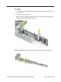
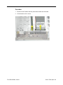
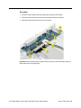
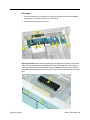
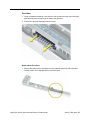
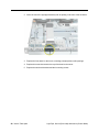
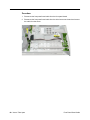
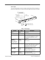
1
Service Source Xserve Xserve, Xserve (Slot Load), and Xserve (Cluster Node) Updated: 7 May 2003 © 2003 Apple Computer, Inc. All rights reserved. Service Source Take Apart Xserve © 2003 Apple Computer, Inc. All rights reserved. General Information Overview Xserve is a server designed to mount into a rack; Apple recommends that you remove the Xserve from the rack before replacing or installing all parts except hard drives. You can replace hard drives while the server is operating and still in the rack. There are three versions of the Xserve server. To identify the versions, check the front panel. The original Xserve includes a tray-load optical drive on the far right side; Xserve (Slot Load) includes a slot-load optical drive. Xserve (Cluster Node) has no optical drive and just one hard drive. Note: For the most part, the procedures in this chapter apply to all versions of the server. When different procedures are required, the version is specified in the topic heading. General Information Xserve Take Apart - 1 Mounting in a Rack For information on mounting Xserve in a rack, see the Xserve User’s Guide. Tools Many take-apart procedures do not require tools. You may, however, find a medium-sized flatblade and Phillips screwdriver useful, as indicated at the beginning of some procedures. If the server is locked, you will also need the server’s Allen wrench key. Server Identifier Light/Button The identifier light on the server’s front panel turns on when internal sensors or a systems administrator detects a problem with the server. (The light can also be turned on by pressing the identifier button.) This indicator will help you locate which server in a rack needs servicing. In addition, you can use the identifier button on the Xserve (Slot Load) and Xserve (Cluster Node) to initiate several firmware commands to the system. See “Entering Firmware Boot Commands From the Front Panel” in the Troubleshooting chapter. Note: A duplicate identifier light/button is on the server’s back panel. Before Opening the Server Serial Number Be sure to write down the server’s serial number before opening it. If the server’s software must be set up after service is complete, the serial number will be required for login. Unlocking the Server If the server is in the locked position (the yellow security LED on the front panel is on), use the Allen key that came with the server to unlock it. Important: When the lock on the server’s front panel is locked, the software ignores the optical drive, keyboard and mouse, and other peripherals connected to the USB and FireWire ports on the server. Shutting Down You must shut down the server before replacing or installing all parts except the hard drives. Before shutting down, be sure to alert users that the server will be unavailable for a period of time. Warning: After shutting down the server, you must wait a few minutes before servicing it to allow internal components to cool. 2 - Xserve Take Apart General Information Electrostatic Discharge (ESD) Precautions Follow these steps to avoid damage from ESD before working inside the server. 1. Shut down the server. 2. If the cable management arm is not in use, unplug all external cables except the power cord. 3. Touch the server’s metal case to discharge static electricity. 4. Unplug the power cord. 5. Slide the server open, remove it from the rack, and place it on a flat surface, preferably covered by an ESD mat. 6. Put on an ESD wrist strap. 7. To avoid static electricity building back up in your body, do not walk around the room until after you have finished working and closed the server. Top Cover The top cover is attached to the rack where the server is mounted. If you are replacing the top cover, you must remove it both from the server and from the rack. For detailed information on how the top cover is mounted in the rack, see the User’s Guide. General Information Xserve Take Apart - 3 Hard Drive The original Xserve and Xserve (Slot Load) include four hard drive bays at the front of the server; Xserve (Cluster Node) includes just one drive bay. Drives come as modules attached to carriers; they are removed from or installed in the server as a unit. Note: Blank drive carriers, which may fill some of the hard drive bays, follow the same take-apart procedure as hard drives. If you are replacing a blank carrier with a drive module, instruct the server’s administrator to keep the blank for possible future use. Blank carriers must be installed in all empty bays to maintain proper airflow through the server. Tools No tools are required for this procedure. Preliminary Steps Before you begin, make sure the drives are in the unlocked position. No other preliminary steps are required. You can replace or install hard drives while the server is running; you do not need to shut down or open the server first. Note: There are two LED indicators on the front of each drive. • The upper LED shows drive status: a green light indicates the drive is good; a yellow or red light indicates the drive should be replaced. • The lower LED shows drive activity: when the light is blinking, the system is reading from or writing to the drive. To avoid losing data, never remove a drive when the lower LED is blinking. WARNING: Drives must be in the unlocked position before you attempt to remove a drive. If the drives are locked, pulling on the drive to remove it could damage the drive handle. Part Location 4 - Xserve Take Apart Hard Drive Procedure 1. Make sure the drive being replaced is not in use by any application and is not being shared by the server. (See the Mac OS X Server documentation for information about shared drives.) 2. Unmount the drive (by using the command-line tools or by dragging the disk icon to the Trash). 3. Press the handle on the front of the drive module so that the handle pops out. 4. Wait for the upper LED on the drive to go out. Then grasp the drive handle, and pull the drive module out of the server. Hard Drive Xserve Take Apart - 5 Opening the Server The server slides open from the front of the rack. The server’s top cover remains in place in the rack; the bottom housing (containing all internal components) should be placed on a sturdy, flat surface. Tools No tools are required for this procedure. You may, however, find a Phillips screwdriver useful in releasing the thumb screws in step 1 below. Preliminary Steps Before you begin this procedure, write down the server’s serial number located on the back panel. If it is necessary to set up the server’s software after service is complete, the serial number will be required for login. 6 - Xserve Take Apart Opening the Server Procedure 1. Release the two thumb screws at the front of the server. Note: The thumbscrews are captive and do not separate from the bottom housing. 2. Grasp the thumbscrews and slide the bottom housing forward part way to expose the two chassis levers. 3. While depressing both levers, pull the bottom housing all the way forward and remove it from the rack. Place the bottom housing on a sturdy, flat surface and ESD mat. Opening the Server Xserve Take Apart - 7 DIMMs Xserve has four memory slots. For the original Xserve, DIMMs must be PC2100 doubledata-rate (DDR) SDRAM (also known as DDR-266 DIMMs). For the Xserve (Slot Load) and Xserve (Cluster Node), DIMMs must be PC2700 DDR SDRAM (also known as DDR333 DIMMs). The DIMMs from older Macintosh computers are not compatible with Xserve. Tools No tools are required for this procedure. Preliminary Steps Before you begin, open the server and place the bottom housing on a sturdy, flat surface. Part Location 8 - Xserve Take Apart DIMMs Procedure 1. Push down the ejectors on the DIMM slot. 2. Holding the DIMM by both top corners, lift it straight up out of the server. Warning: When removing or installing the DIMM, handle it only by the edges. Do not touch its connectors. Lift the DIMM straight up from the connector to remove it, and insert it straight down into the connector to install it. Do not rock the DIMM from side to side. Replacement Note: The DIMM is designed to fit into the slot only one way. Be sure to align the notch in the DIMM with the small rib inside the slot. DIMMs Xserve Take Apart - 9 PCI or AGP Card In the original Xserve and Xserve (Slot Load), there are three slots available for PCI expansion cards. Two slots are on a riser card located at the back left corner of the logic board; an additional slot is on a riser card at the back right corner of the logic board. A PCI card that is 7 inches long can be installed in either riser card; a PCI card that is 12 inches long can be installed only in the dual-slot riser. In addition, an AGP card can be installed in the single-slot riser. The Xserve (Cluster Node) includes just two slots for PCI cards on the dual riser card. Dual-Slot Riser Card • Accommodates long cards (12") or short cards (7") • Standard config comes with PCI video card installed; other cards are CTO options. • Takes 3.3V, 64-bit/66-MHz or 32-bit/33-MHz cards. If one 33-MHz card is installed, all cards run at 33-MHz • Compatible with PCI only Single-Slot Riser Card • Accommodates short cards (7") only • Standard config comes with no card installed; a PCI Gigabit Ethernet card and an AGP video card are available as CTO options for this slot. • Takes 3.3V, 32-bit/66-MHz cards • AGP/PCI riser compatible with PCI cards; AGP/AGP riser compatible with AGP cards Note: Power consumption for all expansion slots, combined, should not exceed 45 W. Tools No tools are required for this procedure. You may, however, find a flatblade screwdriver useful in releasing the thumb screw in step 1 below. Preliminary Steps Before you begin, open the server and place the bottom housing on a sturdy, flat surface. Warning: When removing or installing a PCI or AGP card, handle it only by the edges. Do not touch its connectors or any of the components on the card. Lift the card straight out from the connector to remove it, and insert it straight into the connector to install it. Do not rock the card from side to side and don’t force the card into the slot. Once the replacement card is installed, pull on it gently to check that it is properly connected. 10 - Xserve Take Apart PCI or AGP Card Part Location Card in Single-Slot Riser Card in Dual-Slot Riser Procedure for Card in Dual-Slot Riser 1. Release the thumb screw that secures the card fence to the back of the server. 2. If there are latches on either side of the riser, lift them slightly to release the riser from the logic board. 3. Pull the riser a short distance to the side to disconnect it, and then tilt the riser and attached card(s) up so that the card ports clear the enclosure. Remove the riser and card(s) from the server. PCI or AGP Card Xserve Take Apart - 11 4. Disconnect the card(s) from the riser. Procedure for Card in Single-Slot Riser 1. Release the thumb screw that secures the card fence to the back of the server. 12 - Xserve Take Apart PCI or AGP Card 2. Pull the clip on the riser forward to release the riser from the logic board connector. 3. Disconnect the riser from the logic board and remove the riser and card from the server. 4. Disconnect the card from the riser. PCI or AGP Card Xserve Take Apart - 13 Optical Drive, Xserve Tools The following tools are required for this procedure: • Flatblade screwdriver • Phillips screwdriver If you are removing the drive faceplate, you will also need a jeweler’s (#00) Phillips screwdriver. Preliminary Steps Before you begin, open the server and place the bottom housing on a sturdy, flat surface. Part Location 14 - Xserve Take Apart Optical Drive, Xserve Procedure 1. Disconnect the optical drive cable from the optical drive. 2. Press in on the drive’s side bracket to release the drive from the chassis. 3. Lift up the bracket side of the drive and remove the drive from the server. Optical Drive, Xserve Xserve Take Apart - 15 Note: If you are replacing the optical drive faceplate, do the following: 4. Open the optical drive tray by inserting a straightened paperclip into the manual eject hole on the front of the drive. 5. Turn the drive over so the bottom of the drive faces up. Using a small (#00) Phillips screwdriver, remove the two screws that secure the faceplate. 6. Using a small flat-blade screwdriver, release the latch on the far right end of the faceplate. 7. Remove the faceplate from the drive. 16 - Xserve Take Apart Optical Drive, Xserve Replacement Note: Before installing the replacement drive, you must transfer the side bracket and the guide screws from the original drive to the replacement drive. 8. Remove the two screws that secure the side bracket to the original drive. 9. Remove the bracket and transfer it to the replacement drive, using the two screws from the original drive to secure the bracket. 10. Remove the two guide screws from the side of the original drive and install them on the replacement drive. Optical Drive, Xserve Xserve Take Apart - 17 11. Align the corner of the replacement drive with the two guides in the chassis and press the drive down until you hear it snap into place. 12. Reconnect the optical drive cable to the drive. 18 - Xserve Take Apart Optical Drive, Xserve Optical Drive, Xserve (Slot Load) Tools The only tool required for this procedure is a jeweler’s Phillips (#0) screwdriver. Preliminary Steps Before you begin, open the server and place the bottom housing on a sturdy, flat surface. Part Location Optical Drive, Xserve (Slot Load) Xserve Take Apart - 19 Procedure 1. Disconnect the optical drive cable. 2. Rotate the optical drive clip clockwise to release it. 3. Placing your thumbs on the tab on either side of the drive, carefully slide the drive back from the front bezel. Important: When removing or replacing the optical drive, be careful not to put pressure on the top of the drive or the top of the front bezel that covers the optical drive slot. 4. LIft the drive out of the server. 20 - Xserve Take Apart Optical Drive, Xserve (Slot Load) Replacement Note: Before installing the replacement drive, you must transfer the side brackets and the screws from the original drive to the replacement drive. 5. Remove the mounting screw for the left bracket and transfer the bracket to the new drive, using the same screw to secure it. 6. Remove the three mounting screws for the right bracket and transfer the bracket to the new drive, again using the same screws to secure it. Optical Drive, Xserve (Slot Load) Xserve Take Apart - 21 Optical Drive Cable Tools No tools are required for this procedure. Preliminary Steps Before you begin, open the server and place the bottom housing on a sturdy, flat surface. Part Location 22 - Xserve Take Apart Optical Drive Cable Procedure 1. Disconnect the optical drive cable from the optical drive. 2. Disconnect the cable from the drive interconnect board and remove the cable from the server. Optical Drive Cable Xserve Take Apart - 23 Heatsink, Xserve Note: This procedure applies to the original Xserve only. The heatsink for Xserve (Slot Load) and Xserve (Cluster Node) is part of the processor and should not be removed separately. Tools The only tool required for removing the heatsink is a Phillips screwdriver. Preliminary Steps Before you begin, open the server and place the bottom housing on a sturdy, flat surface. Part Location 24 - Xserve Take Apart Heatsink, Xserve Procedure 1. Release the latch on the heatsink duct from its slot, slide the cover away from the blower, and lift the end of the duct as shown. Remove the duct from the server. 2. Release the three captive screws that secure the heatsink. 3. Lift the heatsink straight up and remove it from the server. Heatsink, Xserve Xserve Take Apart - 25 WARNING: Whenever you remove the heatsink, before reinstalling it, you must replace the thermal grease on the MPU. To replace the grease, do the following: • Using the alcohol pad included with the replacement part or kit, clean off any used thermal grease from the MPU and the bottom of the heatsink. • Using the thermal grease included with the replacement part or kit, apply one dot of fresh grease to the middle of the MPU (or both MPUs if the server is a dual processor). • Spread the grease evenly across the MPU(s) to a thickness of approximately 1 mm. • Carefully align the posts on the heatsink with the holes in the processor card, and lower the heatsink straight down onto the processor. • To ensure the grease spreads evenly over the processor, lightly tighten the screws in the order indicated below. • Again tighten the screws in the order indicated to affix the heatsink securely to the processor. • Replace the heatsink duct on the heatsink. 26 - Xserve Take Apart Heatsink, Xserve Processor, Xserve Tools No tools are required for this procedure. Preliminary Steps Before you begin, do the following: • Open the server and place the bottom housing on a sturdy, flat surface. • Remove the heatsink. Part Location Processor, Xserve Xserve Take Apart - 27 Procedure 1. Lift the processor straight up to disconnect it from the logic board. 2. Remove the processor from the server. 28 - Xserve Take Apart Processor, Xserve Processor, Xserve (Slot Load) and Xserve (Cluster Node) Tools The following tools are required for this procedure • Phillips screwdriver • installation guides (included with the processor service part) Preliminary Steps Before you begin, open the server and place the bottom housing on a sturdy, flat surface. Part Location Processor, Xserve (Slot Load) and Xserve (Cluster Node) Xserve Take Apart - 29 Procedure 1. Using a Phillips screwdriver, remove the three screws that mount the heatsink and processor to the logic board. 2. Carefully lift the heatsink and processor straight up and out of the server. Note: The heatsink is part of the processor; do not attempt to remove the heatsink from the processor. 30 - Xserve Take Apart Processor, Xserve (Slot Load) and Xserve (Cluster Node) Replacement Procedure 1. Insert the threaded end of one of the processor installation guides into the logic board standoff on the right side of the processor connector. Twist the guide until it screws into place. 2. Insert the second processor installation guide into the standoff on the left side of the processor connector and twist until the guide screws into place. Processor, Xserve (Slot Load) and Xserve (Cluster Node) Xserve Take Apart - 31 3. Carefully align the screw holes on the replacement heatsink and processor with the two guides, and lower the unit straight down over the guides until it touches the logic board. 4. To secure the processor to the logic board, press down gently on the top of the heatsink cover in the area directly over the processor's connector. 32 - Xserve Take Apart Processor, Xserve (Slot Load) and Xserve (Cluster Node) 5. Remove the two installation guides. 6. Replace the three mounting screws and secure the processor and heatsink to the logic board. Processor, Xserve (Slot Load) and Xserve (Cluster Node) Xserve Take Apart - 33 Blowers Tools No tools are required for this procedure. Preliminary Steps Before you begin, open the server and place the bottom housing on a sturdy, flat surface. Part Location 34 - Xserve Take Apart Blowers Procedure 1. Disconnect the blower cable from the drive interconnect board. 2. Lift the blower straight up off its mounting pegs and remove it from the server. Blowers Xserve Take Apart - 35 ATA Controller Board Tools No tools are required for this procedure. Preliminary Steps Before you begin, do the following: • Open the server and place the bottom housing on a sturdy, flat surface. • If the unit is an original Xserve, remove the heatsink duct from the heatsink. Note: There is no heatsink duct on the Xserve (Slot Load) and Xserve (Cluster Node). Part Location 36 - Xserve Take Apart ATA Controller Board Procedure 1. Disconnect the blower cable nearest the ATA controller board. 2. Press in on both ends of the clip securing the right side of the ATA controller board and remove the clip from the server. Repeat for the clip on the left side of the board. 3. Lift the ATA controller board straight up to disconnect it from the drive interconnect and logic boards and remove the board from the server. Note: When replacing the ATA controller board, align it over the two pairs of connectors on the drive interconnect and logic boards, making sure the “MLB” arrow printed on it points toward the logic board, and press down. ATA Controller Board Xserve Take Apart - 37 Note: When replacing the ATA controller board clips, orient them so that the long end of each clip points away from the middle of the server. Place the inside edge of the clip into the small notch and then snap down the outer edge of the clip. 38 - Xserve Take Apart ATA Controller Board Locking Mechanism Rod, Xserve Tools No tools are required for this procedure. Preliminary Steps Before you begin, open the server and place the bottom housing on a sturdy, flat surface. Part Location Locking Mechanism Rod, Xserve Xserve Take Apart - 39 Procedure 1. Pull back the latch to release the ribbed end of the locking mechanism rod. 2. Release the two clips on the sides of the front panel board, and pull the board back slightly from the front of the server. 3. Tilt up the ribbed end of the locking mechanism rod and remove the rod from the server. 40 - Xserve Take Apart Locking Mechanism Rod, Xserve Note: When replacing the locking mechanism rod, make sure the first rib in the nylon roller engages with the first slot in the plate below it. Locking Mechanism Rod, Xserve Xserve Take Apart - 41 Locking Mechanism Rod, Xserve (Slot Load) and Xserve (Cluster Node) Tools No tools are required for this procedure. Preliminary Steps Before you begin, open the server and place the bottom housing on a sturdy, flat surface. Part Location 42 - Xserve Take Apart Locking Mechanism Rod, Xserve (Slot Load) and Xserve (Cluster Node) Procedure 1. Pull back the latch to release the gear end of the locking mechanism rod. 2. Tilt up the gear end of the rod and remove the rod from the server. 3. If you are replacing the plastic gear on the end of the rod, slide the gear off the rod. Replacement Procedure 1. To install the gear, slide it onto the notched end of the locking rod, aligning the narrow end of the gear with the end of the rod. Note: Make sure the rib inside the gear engages with the notch in the rod. Locking Mechanism Rod, Xserve (Slot Load) and Xserve (Cluster Node) Xserve Take Apart - 43 2. To install the locking rod, insert the end of the rod with the key hole into the port on the front bezel. Note: Make sure the small circle on the front of the rod aligns with the “unlocked” symbol on the front bezel. 3. Pull back the latch that secures the rod, and gently press the rod down until it clicks into place. 44 - Xserve Take Apart Locking Mechanism Rod, Xserve (Slot Load) and Xserve (Cluster Node) Front Bezel, Xserve (Slot Load) and Xserve (Cluster Node) Tools The only tool required for this procedure is a Phillips screwdriver. Preliminary Steps Before you begin, open the server and place the bottom housing on a sturdy, flat surface. Note: Although the illustrations for this procedure are based on Xserve (Slot Load), the procedure is the same for Xserve (Cluster Node). Part Location Front Bezel, Xserve (Slot Load) and Xserve (Cluster Node) Xserve Take Apart - 45 Procedure 1. Using a Phillips screwdriver, remove the screws that attach the two front bezel brackets to the server, and remove the brackets. 2. Remove the screw that attaches the top of the bezel to the server. 3. Gently pull the front bezel forward and remove it from the server. Important: When removing or replacing the bezel, be careful not to put pressure on the top of the bezel over the optical drive slot. 46 - Xserve Take Apart Front Bezel, Xserve (Slot Load) and Xserve (Cluster Node) Replacement Procedure 1. Transfer the system identifier and power buttons from the original front bezel to the replacement bezel. 2. Remove the bottom row of light pipes from the light pipe assembly and insert them into the bottom row of light pipe holes in the replacement bezel. 3. Replace the front bezel on the server, matching ports/projections with openings. 4. Replace the screw that secures the top of the bezel to the server. 5. Replace the two bezel brackets and their mounting screws. Front Bezel, Xserve (Slot Load) and Xserve (Cluster Node) Xserve Take Apart - 47 Front Buttons, Xserve (Slot Load) and Xserve (Cluster Node) Note: This procedure explains how to remove the power and system ID buttons from the front bezel. Tools The only tool required for this procedure is a Phillips screwdriver. Preliminary Steps Before you begin, do the following: • Open the server and place the bottom housing on a sturdy, flat surface. • Remove the front bezel. Part Location 48 - Xserve Take Apart Front Buttons, Xserve (Slot Load) and Xserve (Cluster Node) Procedure 1. Holding the power button by the plastic tab, lift straight up and remove the button from the front bezel. 2. Repeat for the system ID button. Note: Take care in handling the buttons. The face of each button is loosely attached to the button LEDs and can easily separate. Replacement Note: Position the replacement buttons in the front bezel as illustrated. Front Buttons, Xserve (Slot Load) and Xserve (Cluster Node) Xserve Take Apart - 49 Front Panel Board, Xserve Tools No tools are required for this procedure. Preliminary Steps Before you begin, do the following: • Open the server and place the bottom housing on a sturdy, flat surface. • Remove the locking mechanism. Part Location 50 - Xserve Take Apart Front Panel Board, Xserve Procedure 1. Disconnect the FireWire and front panel board cables from the board. 2. Lift the board out of the server. Front Panel Board, Xserve Xserve Take Apart - 51 Front Panel Board, Xserve (Slot Load) and Xserve (Cluster Node) Tools The only tool required for this procedure is a Phillips screwdriver. Preliminary Steps Before you begin, do the following: • Open the server and place the bottom housing on a sturdy, flat surface. • Remove the locking mechanism. • Remove the front bezel. Part Location 52 - Xserve Take Apart Front Panel Board, Xserve (Slot Load) and Xserve (Cluster Node) Procedure 1. Disconnect the FireWire and front panel board cables from the board. 2. Remove the two screws that mount the front panel board to the chassis. 3. Slide the board back and remove it from the server. Important: When replacing the front panel board, make sure the board slides under the black plastic cover of the light pipe. Front Panel Board, Xserve (Slot Load) and Xserve (Cluster Node) Xserve Take Apart - 53 Light Pipe, Xserve Tools No tools are required for this procedure. Preliminary Steps Before you begin, open the server and place the bottom housing on a sturdy, flat surface. Part Location 54 - Xserve Take Apart Light Pipe, Xserve Procedure 1. Release the two clips on the sides of the front panel board, and pull the board back approximately 1.5 inches from the front of the server. 2. Remove the light pipe from the server. Replacement Note: When repositioning the light pipe against the inside front of the bezel, make sure the projections on the light pipe fit into the holes in the bezel. Then slide the panel board forward until it fits against the light pipe. Note: You may need to lift the light pipe slightly while sliding the front panel board, so that it doesn’t catch the edge of the light pipe. Light Pipe, Xserve Xserve Take Apart - 55 Light Pipe, Xserve (Slot Load) and Xserve (Cluster Node) Tools The following tools are required for this procedure: • Phillips screwdriver • flat-blade screwdriver Preliminary Steps Before you begin, do the following: • Open the server and place the bottom housing on a sturdy, flat surface. • Remove the front bezel. Part Location 56 - Xserve Take Apart Light Pipe, Xserve (Slot Load) and Xserve (Cluster Node) Procedure 1. Using a flat-blade screwdriver, ease first one side and then the other side of the light pipe assembly from its opening in the front of the enclosure. 2. Remove the light pipe assembly from the server. Replacement Procedure 1. Remove the bottom row of light pipes from the light pipe assembly and insert them into the bottom row of light pipe holes in the front bezel. Light Pipe, Xserve (Slot Load) and Xserve (Cluster Node) Xserve Take Apart - 57 2. Insert the rest of the light pipe assembly into its opening in the front of the enclosure. 3. Replace the front bezel on the server, matching ports/projections with openings. 4. Replace the screw that secures the top of the bezel to the server. 5. Replace the two bezel brackets and their mounting screws. 58 - Xserve Take Apart Light Pipe, Xserve (Slot Load) and Xserve (Cluster Node) Front Panel Board Cable Tools No tools are required for this procedure. Preliminary Steps Before you begin, open the server and place the bottom housing on a sturdy, flat surface. Part Location Front Panel Board Cable Xserve Take Apart - 59 Procedure 1. Disconnect the front panel board cable from the front panel board. 2. Disconnect the front panel board cable from the drive interconnect board and remove the cable from the server. 60 - Xserve Take Apart Front Panel Board Cable FireWire Cable Tools No tools are required for this procedure. Preliminary Steps Before you begin, open the server and place the bottom housing on a sturdy, flat surface. Part Location FireWire Cable Xserve Take Apart - 61 Procedure 1. Disconnect the FireWire cable from the front panel board. 2. Disconnect the FireWire cable from the drive interconnect board and remove the cable from the server. 62 - Xserve Take Apart FireWire Cable Drive Interconnect Board Tools No tools are required for this procedure. You may, however, find a Phillips screwdriver useful in releasing the thumb screws in step 2 below. Preliminary Steps Before you begin, open the server and remove the following: • hard drives (blank drive carriers can remain in place) • blowers • ATA controller board Part Location Drive Interconnect Board Xserve Take Apart - 63 Procedure 1. Disconnect the following cables from the drive interconnect board • optical drive cable • power supply cable • locking switch cable • front panel board cable • FireWire cable 2. Release the three thumb screws that secure the drive interconnect board to the chassis. 3. Lift the board slightly to clear the two mounting pegs near both ends of the board. 4. Pull the board back, tilt it up so that the connectors clear the chassis, and remove the board from the server. 64 - Xserve Take Apart Drive Interconnect Board Replacement Note: When installing the drive interconnect board, make sure the board engages with the two mounting pegs (#1 in the illustration below) and the three brackets (#2) on the chassis. Then press the board firmly toward the front of the server, and tighten the three thumbscrews (#3) that secure the board to the chassis. Drive Interconnect Board Xserve Take Apart - 65 Power Supply Tools No tools are required for this procedure. Preliminary Steps Before you begin, do the following: • Open the server and place the bottom housing on a sturdy, flat surface. • If the unit is an original Xserve, remove the heatsink duct from the heatsink. Note: There is no heatsink duct on the Xserve (Slot Load) and Xserve (Cluster Node). Part Location 66 - Xserve Take Apart Power Supply Procedure 1. Release the locking latch on the power supply cable connector and disconnect the cable from the drive interconnect board. 2. Release the thumbscrew that secures the power supply to the chassis. Note: The thumbscrew is captive; you cannot remove it. 3. Grasp the metal flange of the power supply’s connector (on the left side) and lift up to disconnect the power supply from the logic board. Note: You may need to loosen the left side of the power supply and then lift at another point near the front to disengage it. Do not lift the small lip that contains the thumbscrew. 4. Holding the power supply in both hands, remove it from the server. Power Supply Xserve Take Apart - 67 Battery Tools No tools are required for this procedure. You may, however, find a flatblade screwdriver useful in prying up the battery in step 1 below. Preliminary Steps Before you begin, open the server and place the bottom housing on a sturdy, flat surface. Part Location 68 - Xserve Take Apart Battery Procedure 1. Pry up the battery from its holder. Note: You may first need to spread the two tabs on the holder slightly apart to release the battery. 2. Remove the battery from the server. Note: When replacing the battery, make sure the positive (+) end of the battery aligns with the + symbol on the battery holder. Battery Xserve Take Apart - 69 Logic Board Tools No tools are required for this procedure. You may, however, find a Phillips screwdriver useful in releasing the thumb screw in step 1 below. Preliminary Steps Before you begin, open the server and remove the following. • DIMMs • PCI cards • processor • ATA controller board • power supply Note: The replacement logic board does not include the processor, memory DIMMs, or expansion cards. You must transfer these modules from the original board to the new one. Part Location 70 - Xserve Take Apart Logic Board Procedure 1. Release the thumb screw that secures the logic board to the chassis. 2. Move the logic board forward and up slightly to release it from the four mounting pegs. 3. Tilt up the end of the logic board nearest the blowers so that the board ports clear the chassis. 4. Remove the board from the server. Replacement Note: Before installing the replacement logic board, check the heatsink thermal pad on the underside of the board. If the pad is covered with a protective film, remove it. (The protective film is a very thin layer on top of the thermal pad. Be careful to remove only the film, not the pad.) Logic Board Xserve Take Apart - 71 Important: When replacing the logic board, make sure the board’s connectors fit through the appropriate openings in the server’s back panel. Take special care to fit the clear plastic system identifier button through its opening. (The system identifier button is located low on the back panel, to the left of center.) After installing a replacement logic board, be sure to transfer any PCI cards, risers, and DIMMs to the new board. You must also remove the battery insulator tab from the battery holder on the new board. Note: Replacing the logic board in the server changes its Ethernet ID number. The new number is printed on an Ethernet ID label packaged with the replacement logic board. After installing the new logic board, cover the Ethernet ID number on the server’s serial number with the new ID label. 72 - Xserve Take Apart Logic Board Service Source Troubleshooting Xserve © 2003 Apple Computer, Inc. All rights reserved. General Information What’s New Rack-Mounted Server Xserve is designed to be mounted in a rack. Once the server is installed in the rack, you can slide it open from the front to exchange or add parts. For more information, see “Opening the Server” in the Take Apart chapter. Server Identifier Light/Button The identifier light on the server’s front panel turns on when internal sensors or a systems administrator detects a problem with the server. (The light can also be turned on by pressing the identifier button.) This indicator will help you locate which server in a rack needs servicing. In addition, you can use the identifier button to initiate several firmware commands to the system. See “Entering Firmware Boot Commands From the Front Panel” in this chapter. Note: A duplicate identifier light/button is on the server’s back panel. Hot-Pluggable ATA Drives The original Xserve and Xserve (Slot-Load) include four hard drive bays at the front of the server; the original Xserve supports hot-pluggable Apple ATA/100 drive modules and the Xserve (Slot Load) supports ATA/133 drive modules. The Xserve (Cluster Node) includes just one Apple ATA/133 drive module. In the original Xserve and Xserve (Slot Load) drive bays are numbered 1–4, beginning with the far left bay. The bay in which a drive is installed determines its master/slave position, thereby eliminating the need for jumpers or special drive configuration. The drive installed in bay 1 is the master drive and should have the operating system installed on it. In all three models, you can replace or install hard drives while the server is running; you do not need to shut down or open the server first. A status light on the front of each drive indicates when it is safe to remove the drive without losing data. For more information, see “Hard Drive” in the Take Apart chapter. General Information Xserve Troubleshooting - 1 Diagnostics Four types of diagnostics are available for Xserve: • status lights • remote monitoring • Apple Hardware Test • Apple Service Diagnostic For more information, see “Diagnostic Tools” below. DDR Memory The server’s logic board includes four memory slots, which accept double data rate (DDR) SDRAM DIMMs. Memory can be expanded to a maximum of 2 gigabytes. DIMMs used in the original Xserve must fit these specifications: • PC2100 DDR SDRAM, also known as DDR-266 • 2.5 volt • 64-bit wide, 184-pin module • unbuffered (do not use registered or buffered DRAM) • maximum height of 1.3 inches DIMMs used in Xserve (Slot Load) and Xserve (Cluster Node) must fit these specifications: • PC2700 DDR SDRAM, also known as DDR-333 • 2.5 volt • 64-bit wide, 184-pin module • 16 memory devices maximum • unbuffered (do not use registered or buffered DRAM) • maximum height of 1.25 inches Important: DIMMs from older Macintosh computers are not compatible with Xserve. Do not use older DIMMs even if they fit into the DIMM slots. Ports The standard configuration of the original Xserve includes the following ports on the back panel: one or two gigabit Ethernet ports, two FireWire 400 ports, two USB ports, a serial port that supports RS-232 or RS-422 connection, and a VGA monitor port. There is also one FireWire 400 port on the front of the server. The standard configuration of Xserve (Slot Load) includes the following ports on the back panel: one or two gigabit Ethernet ports, two FireWire 800 ports, two USB ports, a serial port that supports RS-232 connection, and a VGA monitor port. There is also one FireWire 400 port on the front of the server. The standard configuration of Xserve (Cluster Node) includes the following ports on the back panel: one gigabit Ethernet port, two FireWire 800 ports, two USB ports, and a serial 2 - Xserve Troubleshooting General Information port that supports RS-232 connection. There is also one FireWire 400 port on the front of the server. System administrators or service providers can connect a laptop computer or terminal to the serial port and then use command-line tools to change settings on the server. The connection requires a serial cable with these specifications: • DB9 connector • 8-bit • no parity • 1 stop bit • 9600 kbps Note: For a diagram of the ports location, see “External Views” in the Views chapter. PCI and AGP Cards In the original Xserve and Xserve (Slot Load), there are three slots available for PCI expansion cards. Two slots are on a riser card located at the back left corner of the logic board; an additional slot is on a riser card at the back right corner of the logic board. A PCI card that is 7 inches long can be installed in either riser card; a PCI card that is 12 inches long can be installed only in the dual-slot riser. In addition, an AGP card can be installed in the single-slot riser. The Xserve (Cluster Node) includes just two slots for PCI cards on the dual riser card. The standard configuration for the original Xserve and Xserve (Slot Load) comes with a VGA video card installed in the bottom slot of the dual-slot riser and a gigabit Ethernet card installed in the single-slot AGP/PCI riser. In addition, a high-end AGP video card is available as a CTO option for these models; it replaces the gigabit Ethernet PCI card in the single-slot riser position and requires installing an AGP/AGP riser card that is bundled with the video card. The Apple Fibre Channel PCI card, which allows connection to Xserve RAID, is also available as a CTO option for Xserve and Xserve (Slot Load); it must be installed in the top slot of the dual-slot riser. Note: Combined power consumption for all expansion slots within one unit should not exceed 45 W. General Information Xserve Troubleshooting - 3 Block Diagram Processor Module PowerPC G4 Microprocessor L3 Cache Main Logic Board DIMM Slots Ethernet PHY U2 memory controller U2PCI and Memory bus bridge Controller and PCI Bus Bridge Network Card Slot Boot ROM Ethernet Port Firewire PHY Firewire Port 1 Firewire PHY Firewire Port 3 Firewire Port 2 PCI Slots PCI Bridge PCI Bridge ATA Interface ATA Interface USB Port 1 USB Port 2 Apple Drive Module Connectors Internal Optical Drive Connector 4 - Xserve Troubleshooting EIDE Bus KeyLargo I/O Device and Disk Controller Serial Port PMU99 Power Controller General Information Resetting the PMU on the Logic Board The PMU (Power Management Unit) is a microcontroller chip that controls all power functions for the server. The PMU is a computer within a computer. Its function is to: • tell the server to turn on, turn off, sleep, wake, idle, etc. • manage system resets from various commands. • maintain parameter RAM (PRAM). • manage the real-time clock. Important: Be very careful when handling the logic board. The PMU is very sensitive and touching the circuitry on the logic board can cause the PMU to crash. If the PMU crashes and is not reset, the battery life goes from about five years to about two days. Note: For the location of the PMU reset button, see “Logic Board Diagram” in the Views chapter. Many system problems can be resolved by resetting the PMU chip. When you have a server that fails to power up, follow this procedure before replacing any modules: 1. Disconnect the power cord and check the battery in the battery holder. The battery should read 3.3 to 3.7 volts. If the battery is bad, replace it, wait ten seconds, and then proceed to step 2. If the battery is good, go directly to step 2. 2. Press the PMU reset button once and then proceed to step 3. Do not press the PMU reset button a second time because it could crash the PMU chip. 3. Wait ten seconds before connecting the power cord and powering on the server. If the server powers on, go to step 4. If the server does not power on, there is something else wrong with it; refer to the “System” section of “Symptom Charts” in this chapter. 4. Run Apple Hardware Test to verify the system. Note: The above procedure resets the server’s PRAM. After resetting the PMU, be sure to reset the time, date, and other system parameter settings. General Information Xserve Troubleshooting - 5 Power Supply Verification To power on, the server’s logic board requires a “trickle” power of +5V. If the system fails to power on, first reset the PMU. Then follow the procedure outlined below to determine whether the problem is related to the power supply. Note: To verify the power supply, you need a volt meter. When connecting the volt meter leads to specific pins, make sure the power supply remains securely plugged into its connector on the logic board. The following figure shows the pins and voltage on the server’s power supply connector, as viewed from above when it is connected to the logic board. +12VDC Pin 13 Pin 1 +12VDC Pin 2 GND GND Pin 14 Pin 3 +12VDC GND Pin 15 Pin 4 +5VDC GND Pin 16 Pin 5 +5VDC GND Pin 17 Pin 6 +5VDC GND Pin 18 Pin 7 +3.3VDC GND Pin 19 Pin 8 +3.3VDC GND Pin 20 Pin 9 +3.3VDC GND Pin 21 Pin 10 -12VDC GND Pin 22 Pin 11 Power On GND Pin 23 Pin 12 +5VSB GND Pin 24 1. Plug a known-good power cord into the server. Do not turn on the server. 2. Connect the black lead of the volt meter to pin 14 of the power supply connector; connect the red lead of the volt meter to pin 1. The volt meter should measure approximately +12V. If you do not get a reading of +12V, recheck the volt meter connections and measure the voltage again. If voltage is still not present, replace the power supply. If you do measure +12V on pin 1, the power supply is likely OK. Go to the next step for further verification. 3. Start up the server by pressing the power button on the front panel. If the server starts up normally, the power supply is OK. If the server does not start up normally, go to the next step. 6 - Xserve Troubleshooting General Information 4. Check to see if the power supply fan is spinning. If it is not, replace the power supply. If it is spinning, go to the next step. 5. Connect the black lead of the volt meter to pin 14 of the power supply connector; connect the red lead to pin 9. The volt meter should measure approximately +3.3V. If you do not get a reading of +3.3V, recheck the volt meter connections and measure the voltage again. If voltage is still not present, replace the power supply. If you do measure +3.3V on pin 9, the power supply is likely OK. Go to the next step for further verification. 6. Connect the black lead of the volt meter to pin 14 of the power supply connector; connect the red lead to pin 4. The volt meter should measure approximately +5V. If you do not get a reading of +5V, recheck the volt meter connections and measure the voltage again. If voltage is still not present, replace the power supply. If you do measure +5V on pin 4, the power supply is likely OK. Go to the next step for further verification. 7. Connect the black lead of the volt meter to pin 14 of the power supply connector; connect the red lead to pin 3. The volt meter should measure approximately +12V. If you do not get a reading of +12V, recheck the volt meter connections and measure the voltage again. If voltage is still not present, replace the power supply. If you do measure +12V on pin 3, the power supply is OK and the testing is complete. You have verified that the power supply is not the cause of the “no apparent power” symptom. RAM and Processor Verification: Power-On Self Test A power-on self test in the server’s ROM automatically runs whenever the server is started up after being fully shut down (the test does not run if the server is only restarted). If the test detects a problem, you will not see a normal sequence of system activity lights on the front panel during startup. Instead, the lights will flash in the following ways: • 2 Flashes: No RAM is installed or detected. • 3 Flashes: Incompatible RAM types are installed. • 4 Flashes: No RAM banks passed memory testing. • 5 Flashes: No good boot images are detected in the boot ROM (and/or there is a bad sys config block). • 6 Flashes: The processor is not usable. General Information Xserve Troubleshooting - 7 Xserve (Slot Load and Cluster Node): Entering Firmware Boot Commands From the Front Panel You can use the system identifier button on the Xserve (Slot Load) and Xserve (Cluster Node) server’s front panel to initiate a limited number of firmware commands to the system without connecting a keyboard or monitor to the server. The commands are listed below; you enter each command with a combination of the system identifier button and a specific light on the front panel. Follow these steps to initiate a command from the front panel. 1. With the power off, hold in the system identifier button while you press the power button. 2. Continue holding in the system identifier button until the top row of blue lights blinks sequentially. 3. Release the system identifier button. The rightmost light in the bottom row turns on. Press the button to light the next light in the bottom row, moving from right to left. Press the button again to change lights. The lights in the bottom row indicate (from right to left): • Light 1 (far right): Start up from the system disc (also ejects any disc in the optical drive) • Light 2: Start up from a network server (NetBoot) • Light 3: Start up from the internal drive (leftmost drive if more than one) • Light 4: Bypass the current startup disk and start up from any other available startup disk • Light 5: Begin target disk mode (all drives, including the optical drive, will show up) • Light 6: Restore the system’s default settings (reset NVRAM) • Light 7: Enter Open Firmware (via the serial port if no monitor and keyboard are connected) 4. When the light for the action you want is on, hold in the system identifier button for at least 2 seconds, until all lights in the top row are on. 5. Release the button. Diagnostic Tools Xserve includes built-in sensors that detect and report on hard drives, internal temperature, blower status or failure, and power status or failure. You can monitor the server’s operation via these sensors and four diagnostic tools: indicator lights on the front of the server, remote monitoring software, Apple Hardware Test, or Apple Service Diagnostic. 8 - Xserve Troubleshooting General Information Status Lights The server’s status lights are shown in the figure and table below. While the illustration is based on the original Xserve, the callouts for the status lights are accurate for all models. Ethernet Card Link Light [not available on Xserve (Cluster Node)] System Activity Lights System Identifier Button/Light Enclosure Lock Power Button /Light Built-In Ethernet Link Light Drive Module Status Light Drive Module Activity Light Table 1: Status Lights Indicator Color Description Power White On and OK Security lock Yellow Lock is engaged System identifier Yellow Indicates a hardware error in the server or that someone has toggled it on; check the server monitoring application for more information Ethernet (lower LED is built-in; upper LED is network card) Green Link No light No connection System activity Blue Two rows of eight LEDs; in server with one processor, rows of lights work in tandem; in dual-processor server, rows operate independently for each processor Drive module (upper LED) Green Powered and running Yellow Warning condition; replace drive Red Problem or failure; replace drive No light Drive can be removed Blinking blue Disk activity; do not remove drive Drive module (lower LED) General Information Xserve Troubleshooting - 9 Remote Monitoring Server Monitor is an application installed with Xserve system software that helps you monitor the following information about the server: • installed operating system • drive status and activity • power supply operation • enclosure and processor temperature • blower operation • security • network operation You can also use Server Monitor to get logs of activity and Apple System Profiler reports on remote servers. Apple Hardware Test Apple Hardware Test is a diagnostic tool for detecting problems with Apple internal hardware components such as logic board, memory, video RAM, and drives. The test does not check externally connected hardware components such as USB or FireWire devices; it also does not check non-Apple devices such as third-party PCI cards. If Apple Hardware Test detects a problem with a computer, it displays an error code, which is defined in the product's Error Code List. Consult the list for appropriate repair procedures associated with the code. 10 - Xserve Troubleshooting General Information All Error Code Lists are included in the Service Diagnostics Matrix, Knowledge Base article 112125. You can also access this matrix by clicking the Service Diagnostics rollover link under any of the product areas on the Service Source home page. Apple Service Diagnostic Apple Service Diagnostic replaces MacTest Pro for Xserve. It tests memory, logic board and components, hard drives, Ethernet cards, and video cards, and complements both Apple Hardware Test and Server Monitor. In addition, it offers the following advantages: • many choices for selecting tests • a looping function where tests can be run once, a specified number of times, or a specified length of time. The looping function is valuable for detecting intermittent problems that take a long time to generate a failure. • detailed information about errors Apple Service Diagnostic can be dowloaded from the Disc Images rollover link on the Service Source home page. General Information Xserve Troubleshooting - 11 Symptom Charts How to Use the Symptom Charts The Symptom Charts included in this chapter will help you diagnose specific symptoms related to the product. Because cures are listed on the charts in the order of most likely solution, try the cures in the order presented. Verify whether or not the product continues to exhibit the symptom. If the symptom persists, try the next cure. Note: If a cure instructs you to replace a module, reinstall the original module before you proceed to the next cure. Startup System is completely dead (no blower movement and power LED is not lit) 1. Verify that the system ID button on the back of the logic board aligns with the opening in the chassis back panel. If it does not, realign the logic board. 2. Verify the power outlet is good. 3. Reseat the ATA controller board. 4. Replace the power cord. 5. Disconnect external devices, including the monitor, and start up the server. 6. Remove internal PCI and AGP cards and start up the server. 7. Verify that the power supply is properly connected to the logic board and drive interconnect board. 8. Verify the front panel board cable is properly connected at both ends. 9. Reseat the front panel board. 10. Verify all cable connections to the drive interconnect board. 11. Replace the power supply. 12. Replace the ATA controller board. 13. Replace the front panel board cable. 14. Replace the front panel board. 15. Replace the drive interconnect board. 12 - Xserve Troubleshooting Startup Symptom Charts 16. Replace the logic board. Note: When installing the new logic board, make sure the ports and ID button on the back of the board align with the openings in the chassis. Memory error message appears on the screen 1. Reseat the DIMMs. 2. Verify that the correct SDRAM DIMMs are installed. 3. Run Apple Hardware Test. If the test finds bad memory, replace the DIMMs one at a time and test until all bad DIMMs are replaced with known-good modules. Flashing question mark appears on the screen 1. Reseat the drive module in the first drive bay. 2. Start up from the system restore CD and check to see if the hard drive shows up on the desktop. If it does, go to step 3. If it does not, go to step 5. 3. Run Disk Utility. Update the driver and restart the server. 4. Reinstall system software using the system restore CD that came with the server. 5. Replace the drive module in the first drive bay. 6. Replace the ATA controller board. Server begins to power up, the blowers and hard drive are spinning, the power LED is lit, but there are no activity lights or video 1. Verify that the system ID button on the back of the logic board aligns with the opening in the chassis back panel. If it does not, realign the logic board. 2. Reset the logic board. Refer to “Resetting the PMU on the Logic Board” in this chapter. 3. Reseat the processor module. 4. Verify all PCI and AGP cards are seated properly. 5. Replace the processor module. 6. Replace the logic board. Note: When installing the new logic board, make sure the ports and ID button on the back of the board align with the openings in the chassis. Server begins to power up, but won’t boot, and top row of activity LEDs continue to light in sequence left to right and then right to left 1. Verify that the system ID button on the back of the logic board aligns with the opening in the chassis back panel. If it does not, realign the logic board. 2. Reset the logic board. Refer to “Resetting the PMU on the Logic Board” in this chapter. 3. Xserve (Slot Load and Cluster Node): Remove the front bezel and make sure the front system IDbutton is not stuck. Reseat the button if necessary. Startup Symptom Charts Xserve Troubleshooting - 13 4. Reseat the front panel board and cable connectors. 5. Replace the front panel board. 6. Replace the logic board. Note: When installing the new logic board, make sure the ports and ID button on the back of the board align with the openings in the chassis. System shuts down intermittently 1. Verify that the system ID button on the back of the logic board aligns with the opening in the chassis back panel. If it does not, realign the logic board. 2. Make sure the power cord is plugged in firmly. 3. Check that the power source is turned on and the correct voltage is present. 4. Make sure the air vents are clear. 5. Replace the power cord. 6. Check that the blower cables are connected and the blowers are operational. 7. Check that the heatsink is properly attached to the processor. 8. Reset the logic board. Refer to “Resetting the PMU on the Logic Board” in this chapter. 9. Replace the power supply. 10. Replace the logic board. Note: When installing the new logic board, make sure the ports and ID button on the back of the board align with the openings in the chassis. System shuts down almost immediately after startup 1. Reset the logic board. Refer to “Resetting the PMU on the Logic Board” in this chapter. 2. Replace the processor module. 3. Replace the power supply. 4. Replace the logic board. Note: When installing the new logic board, make sure the ports and ID button on the back of the board align with the openings in the chassis. 14 - Xserve Troubleshooting Startup Symptom Charts Error Lights Note: Error lights flash before system software loads. Server activity lights flash two times at startup Two flashes mean that no RAM is installed or detected. 1. If no DIMM is present, install a known-good DIMM in the top slot and try again. 2. Reseat the DIMMs. 3. Run Apple Hardware Test. If the test finds bad memory, replace the DIMMs one at a time and test until all bad DIMMs are replaced with known-good modules. 4. Replace the logic board. Note: When installing the new logic board, make sure the ports and ID button on the back of the board align with the openings in the chassis. Server activity lights flash three times at startup Three flashes mean that incompatible RAM types may be installed. Verify that the correct SDRAM DIMMs are installed. 1. Run Apple Hardware Test. If the test finds bad memory, replace the DIMMs one at a time and test until all bad DIMMs are replaced with known-good modules. 2. Replace the logic board. Note: When installing the new logic board, make sure the ports and ID button on the back of the board align with the openings in the chassis. Server activity lights flash four times at startup Four flashes mean that no RAM banks passed memory testing. 1. Run Apple Hardware Test. If the test finds bad memory, replace the DIMMs one at a time and test until all bad DIMMs are replaced with known-good modules. 2. Replace the logic board. Note: When installing the new logic board, make sure the ports and ID button on the back of the board align with the openings in the chassis. Server activity lights flash five or six times at startup Five or six flashes mean that the ROM is probably bad and cannot be fixed. 1. Reseat the processor module. 2. Replace the processor module. 3. Replace the logic board. Note: When installing the new logic board, make sure the ports and ID button on the back of the board align with the openings in the chassis. Error Lights Symptom Charts Xserve Troubleshooting - 15 Video Screen is black, but activity lights flash at startup, drive operates, blowers are running, and power LED is lit 1. Verify that the system ID button on the back of the logic board aligns with the opening in the chassis back panel. If it does not, realign the logic board. 2. Reseat the ATA controller board. 3. Check video card connections and connector pins. 4. Test with a known-good monitor. Replace the monitor, if necessary. 5. Remove all third-party devices. 6. Reseat the video card. 7. Clear parameter RAM. Hold down Command-Option-P-R during startup. 8. Reset the logic board. Refer to “Resetting the PMU on the Logic Board” in this chapter. 9. Replace the video card. 10. Replace the logic board. Note: When installing the new logic board, make sure the ports and ID button on the back of the board align with the openings in the chassis. Screen is black, power LED is lit, blowers spin, activity lights do not flash, and drives do not operate 1. Verify that the system ID button on the back of the logic board aligns with the opening in the chassis back panel. If it does not, realign the logic board. 2. Reset the logic board. Refer to “Resetting the PMU on the Logic Board” in this chapter. 3. Reseat the processor module. 4. Replace the processor module. 5. Replace the logic board. Note: When installing the new logic board, make sure the ports and ID button on the back of the board align with the openings in the chassis. Video is distorted 1. Make sure that the video card driver and firmware are updated to the most recent versions. 2. Refer to the adjustments section of the service manual or owner’s manual for the monitor. Adjust monitor as necessary. 3. Third-party monitors: Try a known-good monitor. 4. Reseat the video card. 5. Replace the video card. 16 - Xserve Troubleshooting Video Symptom Charts Hard Drive Flashing question mark appears on the screen 1. Reseat the drive module in the first drive bay. 2. Start up from the system restore CD and check to see if the hard drive shows up on the desktop. If it does, go to step 3. If it does not, go to step 5. 3. Run Disk Utility. Update the driver and restart the server. 4. Reinstall system software using the system restore CD that came with the server. 5. Replace the drive module in the first drive bay. 6. Replace the ATA controller board. Hard Drive Symptom Charts Xserve Troubleshooting - 17 Internal Optical Drive Optical drive icon does not appear on the desktop 1. If the server is locked, unlock it. 2. Check to see if the optical drive is listed in Apple System Profiler. If it is, go to step 3. If it is not, go to step 9. 3. Verify the correct type of disc is being used. Try using a known-good disc. 4. Try cleaning the disc. (It may not mount if it is dirty or scratched.) 5. If there is a disc stuck in the drive, eject it by restarting the server while holding down the mouse button. 6. Turn off all third-party extensions. 7. Verify the firmware is the most recent version for that drive. Check Software Downloads for any current update. 8. Reinstall system software. 9. Reseat the optical drive cable at both connectors. 10. Replace the optical drive cable. 11. Replace the optical drive. 12. Replace the logic board only if other devices on the bus do not work. Note: When installing the new logic board, make sure the ports and ID button on the back of the board align with the openings in the chassis. Optical drive does not accept CD or DVD disc 1. If the server is locked, unlock it. 2. Verify the disc is not warped. 3. Verify the disc is not the wrong size. Refer to article 58641 “Macintosh: Using Nonstandard Discs in CD-ROM or DVD-ROM Drives.” 4. Replace the optical drive. Original Xserve: Drive tray won’t open 1. If the server is locked, unlock it. 2. Try using a known-good disc. 3. Reseat the optical drive cable at both connectors. 4. Replace the optical drive cable. 5. Replace the optical drive. 18 - Xserve Troubleshooting Hard Drive Symptom Charts Xserve (Slot Load): Disc will not eject 1. If the server is locked, unlock it. 2. Verify the disc is not in use. 3. Drag the disc icon to the trash or select it and press Command-E. 4. Restart the server while holding down the mouse button. 5. Verify that the bezel over the slot is not bent. If it is, gently bend it back into position. 6. Reseat the optical drive cable at both connectors. 7. Replace the optical drive cable. 8. Replace the optical drive. USB Devices At startup, cursor does not move with the Apple mouse 1. If the server is locked, unlock it. 2. Verify that mouse and keyboard connections are secure. 3. If the mouse is connected to the keyboard, connect the mouse to one of the USB ports on the back panel instead. If the mouse works, replace the keyboard. 4. Replace the mouse. 5. If the mouse is connected to one of the USB ports on the back panel, switch to the other USB port. If the mouse operates correctly, replace the logic board. (You can also use Apple System Profiler to verify USB ports.) Note: When installing the new logic board, make sure the ports and ID button on the back of the board align with the openings in the chassis. No response to any key on keyboard 1. If the server is locked, unlock it. 2. Verify that keyboard and mouse connections are secure. 3. Remove all USB devices, except the keyboard and mouse. If the keyboard operates correctly, troubleshoot the other USB devices. 4. Switch the keyboard to a different USB port. If the keyboard operates correctly, replace the logic board. (You can also use Apple System Profiler to verify USB ports.) 5. Relaunch Finder. 6. Start up from the system installation CD or system restore CD that came with the server. If the keyboard operates, reinstall system software. 7. Replace the keyboard. 8. Replace the logic board. Note: When installing the new logic board, make sure the ports and ID button on the back of the board align with the openings in the chassis. USB Devices Symptom Charts Xserve Troubleshooting - 19 FireWire Devices FireWire device connected to port on back panel: No external FireWire device icon appears on the desktop 1. If the server is locked, unlock it. 2. Verify that the FireWire device is turned on and the FireWire cable is securely connected to the device and the server. 3. If the device requires external power, make sure it is plugged in. 4. Check that the FireWire device is listed in Apple System Profiler. If it is, go to step 5. If it is not, go to step 6. 5. Check the FireWire device documentation to see if additional drivers are required. If so, make sure the drivers are installed. 6. Check for broken pins, dust, dirt, or wear on both FireWire cable connectors, the device FireWire port, and the server FireWire port. 7. Reconnect the FireWire device to another FireWire port on the server. If the server has a bad FireWire port, replace the logic board. 8. Replace the FireWire cable. 9. Replace the FireWire device. 10. Replace the logic board. Note: When installing the new logic board, make sure the ports and ID button on the back of the board align with the openings in the chassis. FireWire device connected to port on front panel: No external FireWire device icon appears on the desktop 1. If the server is locked, unlock it. 2. Verify that the FireWire device is turned on and the FireWire cable is securely connected to the device and the server. 3. If the device requires external power, make sure it is plugged in. 4. Check that the FireWire device is listed in Apple System Profiler. If it is, go to step 5. If it is not, go to step 6. 5. Check the FireWire device documentation to see if additional drivers are required. If so, make sure the drivers are installed. 6. Check for broken pins, dust, dirt, or wear on both FireWire cable connectors, the device FireWire port, and the server FireWire port. 7. Reconnect the FireWire device to one of the two FireWire ports on the back panel. If the front FireWire port is bad, reseat the FireWire cable on the front panel board and the interconnect board. Replace front panel board. Replace internal FireWire cable. 8. Replace the FireWire cable. 9. Replace the FireWire device. 20 - Xserve Troubleshooting FireWire Devices Symptom Charts Network Problems Server cannot be seen on network 1. Open the Network system preference and select the Ethernet option. Verify that you can now see devices on the network. 2. Boot the server from the Net-install CD. Go to another computer on the same subnet and start Server Assistant. If the server can be seen, the server hardware should be functioning correctly. Check the software configuration on the server, or reinstall and reconfigure the server. 3. Try a known-good Ethernet cable. 4. Clear parameter RAM. Hold down Command-Option-P-R during startup. 5. Try connecting to a known-good Ethernet port at the wall or external hub. 6. Verify that other users are experiencing the same problem. If so, contact the network administrator. 7. If connected to an Ethernet card, reseat the card. 8. If connected to an Ethernet card, replace the card. 9. Replace the logic board. Note: When installing the new logic board, make sure the ports and ID button on the back of the board align with the openings in the chassis. Network Problems Symptom Charts Xserve Troubleshooting - 21 Miscellaneous ID buttons/lights on the back and front of the server are always on, even though Server Monitor reports no problems Make sure the ports and ID button on the back of the logic board align correctly with the openings in the chassis. Original Xserve: Security light on the front of the server is always on, even though the server is unlocked. Or service light turns on and off, even though Server Monitor does not report any problems. Make sure the metal locking switch at the front of the server is not bent downward. If it is, bend it back to its original position, as shown below. 22 - Xserve Troubleshooting Miscellaneous Symptom Charts Service Source Views Xserve © 2003 Apple Computer, Inc. All rights reserved. Internal Views, Xserve Exploded View Battery 922-4028 Logic Board 661-2660 Dual-Slot Riser Card 922-5140 Video Card, PCI 661-2679 Gigabit Ethernet Card 661-2677 AGP/PCI Single-Slot Riser Card 922-5166 AGP/AGP Single-Slot Riser Card 922-5250 Power Supply 661-2664 DIMM Slots (4) 256 MB DDR DIMM 661-2658 512 MB DDR DIMM 661-2659 1 GHz Uni Processor 661-2661 Drive Interconnect Board 922-5167 Blowers 922-5268 FireWire Cable 922-5152 CD Drive 661-2663 Optical Drive Cable 922-5151 ATA Controller Board 922-5144 Front Panel Board 922-5141 Front Panel Board Cable 922-5153 60 GB Hard Drive Module 661-2654 120 GB Hard Drive Module 661-2655 Internal Views, Xserve Xserve Views - 1 Logic Board Serial Port USB Ports System Identifier Button FireWire Ports Ethernet Port Dual-Slot Riser Connector SingleSlot Riser Connector PMU Reset Button Reset Button Interrupt Button Power Supply Connector DIMM Slots Processor Connector Bridge Board Connectors 2 - Xserve Views Internal Views, Xserve External Views, Xserve Front Panel Ethernet Card Link Light CD Drive Open Button FireWire Port System Identifier Button/Light System Activity Lights Enclosure Lock Power Button /Light CD Drive Apple Drive Modules Bays (4) Securing Thumbscrews (2) Built-In Ethernet Link Light Drive Module Status Light Drive Module Activity Light Back Panel System Identifier Button/Light Gigabit Ethernet Port(s) PCI Card Expansion Slots (3) Power Socket FireWire Ports (2) USB Ports (2) External Views, Xserve Monitor Port Serial Console Port Xserve Views - 3 Internal Views, Xserve (Slot Load) Exploded View Battery 922-4028 Logic Board 661-2741 Dual-Slot Riser Card 922-5847 Video Card, PCI 661-2679 Gigabit Ethernet Card 661-2832 AGP/PCI Single-Slot Riser Card 922-5166 AGP/AGP Single-Slot Riser Card 922-5250 Power Supply 661-2835 DIMM Slots (4) 256 MB DDR DIMM 661-2726 512 MB DDR DIMM 661-2727 1.33 GHz Uni Processor 661-2833 1.33 GHz Multiprocessor 661-2834 Drive Interconnect Board 922-5814 Blowers 922-5816 FireWire Cable 922-5152 CD Drive 661-2743 661-2813 Front Bezel 922-5822 Optical Drive Cable 922-5151 ATA Controller Board 922-5817 Front Panel Board 922-5813 Front Panel Board Cable 922-5815 60 GB Hard Drive Module 661-2830 180 GB Hard Drive Module 661-2829 4 - Xserve Views Internal Views, Xserve (Slot Load) Logic Board Serial Port USB Ports FireWire Ports System Identifier Button Ethernet Port SingleSlot Riser Connector Dual-Slot Riser Connector PMU Reset Button Reset Button Interrupt Button Power Supply Connector DIMM Slots Processor Connector Bridge Board Connectors Internal Views, Xserve (Slot Load) Xserve Views - 5 External Views, Xserve (Slot Load) Front Panel System Activity Lights Ethernet Card Link Light Slot-Load Optical Drive FireWire 400 Port System Identifier Button/Light Enclosure Lock and Status Light Drive Module Status Light Power Button /Light Apple Drive Module (4 Bays) Securing Thumbscrews (2) Built-in Ethernet Link Light Drive Module Activity Light Back Panel System Identifier Button/Light Gigabit Ethernet Port(s) PCI Card Expansion Slots (3) Power Socket FireWire 800 Ports (2) USB Ports (2) Serial Console Port 6 - Xserve Views VGA Monitor Port External Views, Xserve (Slot Load) Internal Views, Xserve (Cluster Node) Exploded View Battery 922-4028 Logic Board 661-2741 Dual-Slot Riser Card 922-5847 DIMM Slots (4) 256 MB DDR DIMM 661-2726 512 MB DDR DIMM 661-2727 Power Supply 661-2835 1.33 GHz Multiprocessor 661-2834 Drive Interconnect Board 922-5898 Blowers 922-5816 FireWire Cable 922-5152 Front Bezel 922-5903 ATA Controller Board 922-5817 Front Panel Board 922-5813 Front Panel Board Cable 922-5815 60 GB Hard Drive Module 661-2830 Internal Views, Xserve (Cluster Node) Xserve Views - 7 Logic Board Serial Port USB Ports FireWire Ports System Identifier Button Ethernet Port SingleSlot Riser Connector Dual-Slot Riser Connector PMU Reset Button Reset Button Interrupt Button Power Supply Connector DIMM Slots Processor Connector Bridge Board Connectors 8 - Xserve Views Internal Views, Xserve (Cluster Node) External Views, Xserve (Cluster Node) Front Panel System Activity Lights Built-in Ethernet Link Light FireWire 400 Port System Identifier Button/Light Enclosure Lock and Status Light Power Button /Light Drive Module Status Light Securing Thumbscrews (2) Drive Module Activity Light Back Panel System Identifier Button/Light Gigabit Ethernet Port PCI Card Expansion Slots (2) Power Socket FireWire 800 Ports (2) USB Ports (2) Serial Console Port External Views, Xserve (Cluster Node) Xserve Views - 9 Service Source Verification of Basic Services Xserve © 2003 Apple Computer, Inc. All rights reserved. How to Start Up From CD Starting up Xserve from a CD-ROM disc is useful when you need to: • install the server's operating system • install a software component • isolate hardware versus software issues Preliminary Steps To start up the server from a CD, you must have physical access to it. You cannot do this remotely. If you need to start up Xserve using a connected keyboard, you must connect both a keyboard and monitor before beginning. Procedure 1. Make sure Xserve is turned off. 2. Turn on Xserve. Quickly eject the CD tray. Insert the Installation CD, and close the CD tray. Try to perform these steps as quickly as possible. 3. Turn off Xserve. 4. Turn on Xserve again. 5. Press and hold the 'Service ID' button on the front panel of the server until it begins to start up from the CD. This may take more than 5 seconds. 6. If these steps have worked, Xserve should start up from the CD, and the Installer Setup assistant should open. Follow the remaining steps only if the server did not start up in Step 5. 7. Turn off Xserve, and connect a keyboard and monitor to the server. 8. Turn on Xserve while holding down the 'C' key on the keyboard. Xserve should start up with the CD and the Installer Setup assistant should open. How to Start Up From CD Xserve Verification of Basic Services - 2 How to Verify the Server's IP and Hardware (MAC) Address Verifying the server’s IP and hardware address is useful as a first step in remote software installation or to verify Xserve hardware and basic network connectivity. Preliminary Steps Make sure that the server you want to remotely install software on is started up from the Installation CD. Procedure Option A (Server Assistant) 1. Open Server Assistant from Admin system. 2. Select the "Install Mac OS X Server SW" option. The "remote installation" screen should appear with a list of all Xserve servers in the subnet. 3. Select the target Xserve from the list. Important: You will need the first 8 characters of the server's serial number in order to authenticate from this screen. Option B (Terminal) 1. Open the Terminal application (Applications/Utilities). 2. Type: cd/System/Library/ServerSetup 3. Press Return. 4. Type: ./sa_srchr 224.0.0.1 5. Press Return. The target Xserve's IP address, hardware (MAC) address, and DNS name (if applicable) should appear. 3 - Xserve Verification of Basic Services How to Verify the Server's IP and Hardware (MAC) Address How to Discover Xserve on Your Network Follow the steps outlined below to remotely administer Xserve. Note: This procedure verifies basic connectivity to Xserve, which can help isolate hardware versus software issues. Preliminary Steps Make sure that you are doing these steps on an Admin computer with Mac OS X 10.1.5 Server or Mac OS X 10.1.5 remote admin utilities. You must be logged in to that computer with an Admin account. Also, make sure that the server you want to remotely discover is started up from the Installer CD. Procedure Option A If you already know your Xserve's IP address you can quickly verify network connectivity by using the following command from a remote admin system using the Terminal application: ping 17.XXX.XXX.XXX (the X characters represent numerical IP addresses) Or ping <yourserver.yourdomainname.yourdomainextension> Your domain extension will resemble something like: .com, .edu, .org Option B If you wish to automatically discover your Xserve using the Server Assistant, follow these steps: 1. Open Server Assistant from a remote admin computer. 2. Select the "Install Mac OS X Server Software" option. The "Remote installation" screen appears. All Xserve computers on the same TCP/IP subnet appear in a list format. 3. Select the appropriate Xserve. How to Discover Xserve on Your Network Xserve Verification of Basic Services - 4 Note: To continue, the first 8 characters of the Xserve serial number are required to authenticate. The password is case-sensitive. If you encounter difficulty using this password please see technical document 61644: "Xserve: Initial Password Is Case Sensitive". Option C As an alternative to using Server Assistant, the following procedure may be performed using the Terminal application. 1. Open the Terminal application on the Admin computer. 2. Type: cd/System/Library/ServerSetup 3. Press Return. 4. Type: ./sa_srchr 224.0.0.1 5. Press Return. 6. Verify that Xserve shows its correct IP address, hardware (MAC) address, and DNS name (if applicable). 5 - Xserve Verification of Basic Services How to Discover Xserve on Your Network How to Check for Local Hard Drive Issues Follow the steps outlined below if you suspect issues with Xserve's hard disk, and you have physical access to the server. Preliminary Steps In order to follow these steps, you must have physical access to Xserve. You cannot perform this procedure remotely. A keyboard and monitor must be connected to the server before you begin. If you wish to check the startup disk (or volume), you must start up Xserve from its Installation CD first, then open Disk Utility from the first Installation screen. Procedure 1. Log in to Xserve using the connected keyboard and monitor. 2. Open Disk First Aid, which is located in /Applications/Utilities. 3. Select the volume you wish to examine. Note: You cannot select the startup volume unless you started up the server from the Installation CD. 4. Click Verify to check the disk. 5. If there were any issues found by Disk First Aid, answer 'y' to any prompts presented. 6. Repeat steps 4 and 5 until no issues are reported. If Disk First Aid reports the same error(s) after repeating the process, you should reformat the hard disk. Warning: Reformatting or reinitializing the hard disk erases all information stored on it. Make sure you have a backup of all files you may have created and any preinstalled software that came with Xserve. How to Check for Local Hard Drive Issues Xserve Verification of Basic Services - 6 How to Remotely Check for Hard Drive Issues Follow the steps outlined below if you suspect issues with Xserve's hard disk, and you do not have physical access to the server. Preliminary Steps You must have the server's IP address and Admin (or root) password before performing this procedure. Xserve's default password is the first 8 characters of its serial number. Procedure 1. Log in to Xserve. 2. Type: mount 3. Press Return. A list of volumes that are available to the file system appears. Look for the volume that is at the root level "/". This is the server's startup volume, or "/dev/rdisk0s10". 4. Type: fsck_hsf -n <insert startup volume path> For example: fsck_hsf -n /dev/rdisk0s10 5. Press Return. A file system check is performed. This is basically the equivalent of using Disk First Aid. 6. If "fsck" finds any issues, type 'y' to continue. 7. Repeat steps 4 through 6 until "fsck" finds no errors. If "fsck" reports the same error(s) after repeating the process, you should reformat the hard disk. Warning: Reformatting or reinitializing the hard disk erases all information stored on it. Make sure you have a backup of all files you may have created and any preinstalled software that came with Xserve 7 - Xserve Verification of Basic Services How to Remotely Check for Hard Drive Issues How to Erase (Reformat) a Local Xserve Hard Drive Follow the steps outlined below if you wish to reformat Xserve's hard disk and you have physical access to the server. Preliminary Steps In order to follow these steps, you must have physical access to Xserve. You cannot perform this procedure remotely. A keyboard and monitor must be connected to the server before you begin. Procedure 1. Start up Xserve from the Installation CD first and open Disk Utility from the first Installation screen. 2. Click the Erase tab from the Disk Utility screen. 3. Select appropriate options from this screen and click OK to begin reformatting the hard disk. Warning: Reformatting or reinitializing the hard disk erases all information stored on it. Make sure you have a backup of all files you may have created and any preinstalled software that came with Xserve. How to Erase (Reformat) a Local Xserve Hard Drive Xserve Verification of Basic Services - 8 How to Remotely Erase (Reformat) a Hard Drive Follow the steps outlined below if you wish to reformat Xserve's hard disk, and you do not have physical access to the server. Preliminary Steps You must have the server's IP address and Admin (or root) password before performing this procedure. Xserve's default password is the first 8 characters of its serial number. Procedure 1. Log in to Xserve. 2. Type: mount 3. Press Return. A list of volumes that are available to the file system appears. Look for the volume that is at the root level "/". This is the server's startup volume, or "/dev/ rdisk0s10". Note: You cannot reformat the startup volume. 4. Type: umount <insert volume name> For example: umount Scratch 5. Press Return. This makes the volume unavailable to the file system, or "unmounts" it, which is required prior to reformatting it. 6. Type: newfs_hfs -v <insert volume name> <insert BSD device name> For example: newfs_hfs -v Scratch /dev/disk0s11 7. Press Return. The disk is reformatted. 8. Type: shutdown -r now 9. Press Return. Xserver restarts. Warning: Reformatting or reinitializing the hard disk erases all information stored on it. Make sure you have a backup of all files you may have created and any preinstalled software that came with Xserve. 9 - Xserve Verification of Basic Services How to Remotely Erase (Reformat) a Hard Drive How to Verify Xserve Is Accepting Connections There are several methods for determining if Xserve has successfully started up and is providing basic services. Using a terminal connection to accomplish this task provides the most flexibility. Note: You will not be able to perform this procedure if the Xserve is not fully started up. Preliminary Steps You must have the IP address and an Admin (or root) password of the server you wish to start up before performing this procedure. Procedure 1. At the Admin computer, type the following command: ssh <admin>@<Xserve IP address> 2. You should be presented with a password prompt. At this prompt, type the admin password. The Xserve's default password is the first 8 characters of the Xserve's serial number, and is case sensitive. 3. The following should appear if you have logged in correctly: Welcome To Darwin! :~] admin% 4. To determine if any additional drives are available to the file system, at the command prompt type: df 5. To verify more information about the Xserve's volumes, including which volume the Xserve was actually started up from, open Apple System Profiler from the Terminal application by typing: AppleSystemProfiler | grep boot You may also run Apple System Profiler with no options for a complete report of the Xserve system configuration information. How to Verify Xserve Is Accepting Connections Xserve Verification of Basic Services - 10 How to Connect Using Server Monitor Follow the steps outlined below any time you need to verify that you can remotely administer Xserve. Prelimary Steps You must have the IP address and an Admin (or root) password of the Xserve you wish to start up before performing this procedure. Note: Xserve's default password is the first 8 characters of its serial number. Procedure 1. From the Admin computer, open Server Monitor (/Applications/Utilities). 2. A list of all Xserve servers that have been previously added by Server Monitor appears. 3. Locate the Xserve you wish to administer from the list. 4. If the Xserve you wish to administer appears in the list, select it, then click the appropriate tab at the bottom of Server Monitor. 5. If the Xserve you wish to administer does not appear, then click Add Server. Type the IP address, login name, and password for the Xserve server. The server should appear in the list. If it does not appear, you may have network or hardware issues. 6. Use the tabs at the bottom of the Server Monitor window to check status of Xserve's various systems. Note: If the logic board has been replaced, see technical document 106924: “Xserve: How to Remotely Install Mac OS X Server After Logic Board Replacement.” 11 - Xserve Verification of Basic Services How to Connect Using Server Monitor How to Start up the Server Using an External Drive Starting up Xserve from an external drive is useful when you need to run diagnostics or isolate internal CD-ROM drive issues. Preliminary Steps In order to start up the server from an external drive, you must have: • another FireWire drive or system, such as an external FireWire hard drive, or a Macintosh computer that is capable of starting up using Target Disk Mode (for example a PowerBook or iBook) • a version of Xserve software (Mac OS X Server 10.1.5) capable of starting up Xserve already installed on the external drive • a keyboard and display connected to server • physical access to the server • a keyboard to locally select a volume Procedure for Local External Drive 1. Make sure that Xserve is turned off. 2. Connect a FireWire cable between the external FireWire drive or computer and Xserve. 3. Hold down the 'T' key on the keyboard of the external FireWire-capable computer while it starts up to put it into FireWire Target Disk Mode. 4. Turn on Xserve while holding down the 'Option' key on Xserve's keyboard. The Startup Manager appears. 5. Select the appropriate drive you wish to start up from in the Startup Manager window, and then click the right arrow button. 6. Xserve should start up to the external FireWire drive or computer. Procedure for Remote External Drive 1. Open the Terminal application on a remote computer. 2. Log in as an Admin user on the Xserve. How to Start up the Server Using an External Drive Xserve Verification of Basic Services - 12 3. Type: bless -folder /Volumes/<your drive name/System/Library/ CoreServices -setOF 4. Press Return. 5. Type: Reboot 6. Press Return. 7. Xserve should start up from the external FireWire drive or computer. 13 - Xserve Verification of Basic Services How to Start up the Server Using an External Drive Troubleshooting Authentication Issues Symptom A warning message such as “authenticity of host cannot be established” appears when you attempt to log in to Xserve remotely. Solution Delete and then recreate the authentication keys related to the specific host. Important: • Make sure you have the IP address and Admin login information for the appropriate Xserve. • Verify the first 8 characters of the serial number that correspond to the appropriate Xserve. • Make sure that the administration computer has Mac OS X version 10.1 or later installed. When authentication of the RSA host key is invalid, the warning message states which hosts file, and line number within the file, is invalid. For example: Offending key in /Users/admin/.ssh/known_hosts2:42 In this example, known_hosts2 has the offending authentication key and the host on line 42 of known_hosts2 is the line that needs to be deleted. Note: The warning message has some very stern wording; however, there are nonthreatening reasons for authentication keys not matching. Troubleshooting Authentication Issues Xserve Verification of Basic Services - 14 Error message example: @@@@@@@@@@@@@@@@@@@@@@@@@@@@@@@@@@@@@@@ @@@@@@@@@@@@@@@@@@@@ @ WARNING: POSSIBLE DNS SPOOFING DETECTED! @ @@@@@@@@@@@@@@@@@@@@@@@@@@@@@@@@@@@@@@@ @@@@@@@@@@@@@@@@@@@@ The RSA host key for xxxxxx has changed, and the key for the according IP address 17.xxx.xxx.xx is unchanged. This could either mean that DNS SPOOFING is happening or the IP address for the host and its host key have changed at the same time. Offending key for IP in /Users/admin/.ssh/known_hosts2:44 @@@@@@@@@@@@@@@@@@@@@@@@@@@@@@@@@@@@@@@ @@@@@@@@@@@@@@@@@@@@ @ WARNING: REMOTE HOST IDENTIFICATION HAS CHANGED! @ @@@@@@@@@@@@@@@@@@@@@@@@@@@@@@@@@@@@@@@ @@@@@@@@@@@@@@@@@@@@ IT IS POSSIBLE THAT SOMEONE IS DOING SOMETHING NASTY! Someone could be eavesdropping on you right now (man-in-the-middle attack)! It is also possible that the RSA host key has just been changed. The fingerprint for the RSA key sent by the remote host is xx:xx:xx:xx:xx:xx:xx:xx:xx:xx:xx:xx. Please contact your system administrator. Add correct host key in /Users/admin/.ssh/known_hosts2 to get rid of message. Offending key in /Users/admin/.ssh/known_hosts2:42 RSA host key for xxxxxxx has changed and you have requested strict checking. The authenticity of host 'xxxxxx (17.xxx.xxx.xx)' can't be established. RSA key fingerprint is xx:xx:xx:xx:xx:xx:xx:xx:xx:xx:xx:xx. Are you sure you want to continue connecting (yes/no)? 15 - Xserve Verification of Basic Services Troubleshooting Authentication Issues How to Delete and Recreate Authentication Keys 1. Open TextEdit on the Admin computer. Located in /Applications/ 2. Open the file: ~/.ssh/known_hosts or ~/.ssh/known_hosts2 All fingerprints from previous connections appear. 3. Locate host name or IP address of the server within the text you want to connect to using ssh. This is the on the line number mentioned in the warning message. 4. Delete the line containing the host name or IP address. Press Control-K in TextEdit to delete the entire line including all authentication keys related to this host. 5. Save the TextEdit file. 6. Quit TextEdit. 7. Open Terminal on the Admin computer. 8. Type the following at the command prompt: ssh -l root <IP Address> 9. Press Return. A prompt asks to recreate the certificate. 10. Type 'y' at the prompt to recreate the certificate. A new fingerprint appears and a prompt asks to continue with the connection process. Troubleshooting Authentication Issues Xserve Verification of Basic Services - 16