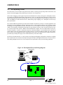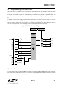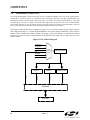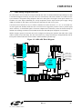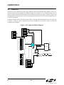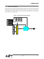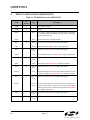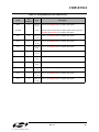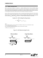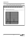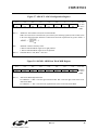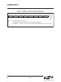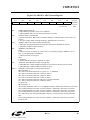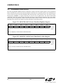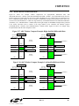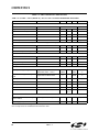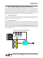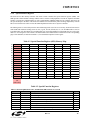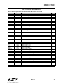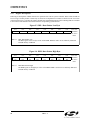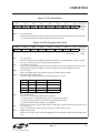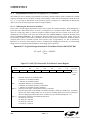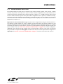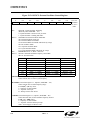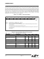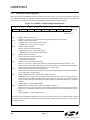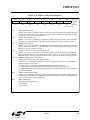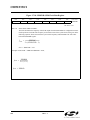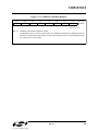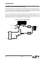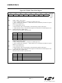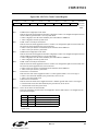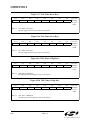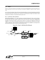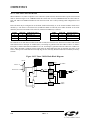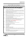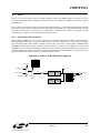
1
C8051F330/1 8k ISP FLASH MCU Family ANALOG PERIPHERALS - 10-Bit ADC (‘F330 only) • Up to 200 ksps • Up to 16 External Single-Ended or Differential Inputs • VREF from Internal VREF, External Pin or VDD • Internal or External Start of Conversion Source • Built-in Temperature Sensor - 10-Bit Current Output DAC (‘F330 only) - Comparator • Programmable Hysteresis and Response Time • Configurable as Interrupt or Reset Source • Low Current (0.4 µA) ON-CHIP DEBUG - On-Chip Debug Circuitry Facilitates Full Speed, Non- HIGH SPEED 8051 µC CORE - Pipelined Instruction Architecture; Executes 70% of Instructions in 1 or 2 System Clocks - Up to 25 MIPS Throughput with 25 MHz Clock - Expanded Interrupt Handler MEMORY - 768 Bytes Internal Data RAM (256 + 512) - 8k Bytes FLASH; In-system programmable in 512-byte Sectors DIGITAL PERIPHERALS - 17 Port I/O; All 5 V tolerant with High Sink Current - Hardware Enhanced UART, SMBus™, and Enhanced - Intrusive In-System Debug (No Emulator Required!) Provides Breakpoints, Single Stepping, Inspect/Modify Memory and Registers Superior Performance to Emulation Systems Using ICEChips, Target Pods, and Sockets Low Cost, Complete Development Kit - SPI™ Serial Ports Four General Purpose 16-Bit Counter/Timers 16-Bit Programmable Counter Array (PCA) with three Capture/Compare Modules Real Time Clock Mode using PCA or Timer and External Clock Source CLOCK SOURCES - Two Internal Oscillators: • 24.5 MHz with ±2% Accuracy Supports crystal-less UART SUPPLY VOLTAGE 2.7V TO 3.6V - Typical Operating Current:6.4mA @ 25 MHz; 9µA @ 32 kHz Typical Stop Mode Current:0.1 µA - TEMPERATURE RANGE: -40°C TO +85°C - Operation 80/40/20/10 kHz Low Frequency, Low Power • External Oscillator: Crystal, RC, C, or Clock (1 or 2 Pin Modes) Can Switch Between Clock Sources on-the-fly; Useful in Power Saving Modes 20-PIN MICRO LEAD PACKAGE A M U X 10-bit 200ksps ADC TEMP SENSOR DIGITAL I/O 10-bit Current DAC + VOLTAGE COMPARATOR 24.5 MHz PRECISION INTERNAL OSCILLATOR UART SMBus SPI PCA Timer 0 Timer 1 Timer 2 Timer 3 CROSSBAR ANALOG PERIPHERALS Port 0 Port 1 P2.0 LOW FREQUENCY INTERNAL OSCILLATOR HIGH-SPEED CONTROLLER CORE 8KB ISP FLASH FLEXIBLE INTERRUPTS Preliminary Rev. 1.1 12/03 8051 CPU (25MIPS) DEBUG CIRCUITRY 768 B SRAM POR Copyright © 2003 by Silicon Laboratories WDT C8051F330/1-DS11 This information applies to a product under development. Its characteristics and specifications are subject to change without notice. C8051F330/1 Notes 2 Rev. 1.1 C8051F330/1 TABLE OF CONTENTS 1. SYSTEM OVERVIEW .........................................................................................................13 1.1. CIP-51™ Microcontroller Core ......................................................................................17 1.1.1. Fully 8051 Compatible ..........................................................................................17 1.1.2. Improved Throughput ............................................................................................17 1.1.3. Additional Features................................................................................................18 1.2. On-Chip Memory ............................................................................................................19 1.3. On-Chip Debug Circuitry ................................................................................................20 1.4. Programmable Digital I/O and Crossbar .........................................................................21 1.5. Serial Ports.......................................................................................................................21 1.6. Programmable Counter Array .........................................................................................22 1.7. 10-Bit Analog to Digital Converter.................................................................................23 1.8. Comparators ....................................................................................................................24 1.9. 10-bit Current Output DAC.............................................................................................25 2. ABSOLUTE MAXIMUM RATINGS ..................................................................................26 3. GLOBAL DC ELECTRICAL CHARACTERISTICS ......................................................27 4. PINOUT AND PACKAGE DEFINITIONS........................................................................28 5. 10-BIT ADC (ADC0, C8051F330 ONLY) ...........................................................................35 5.1. Analog Multiplexer .........................................................................................................36 5.2. Temperature Sensor.........................................................................................................37 5.3. Modes of Operation.........................................................................................................38 5.3.1. Starting a Conversion.............................................................................................38 5.3.2. Tracking Modes .....................................................................................................39 5.3.3. Settling Time Requirements ..................................................................................40 5.4. Programmable Window Detector ....................................................................................46 5.4.1. Window Detector In Single-Ended Mode .............................................................48 5.4.2. Window Detector In Differential Mode.................................................................49 6. 10-BIT CURRENT MODE DAC (IDA0, C8051F330 ONLY) ..........................................51 6.1. IDA0 Output Scheduling.................................................................................................51 6.1.1. Update Output On-Demand ...................................................................................51 6.1.2. Update Output Based on Timer Overflow .............................................................52 6.1.3. Update Output Based on CNVSTR Edge ..............................................................52 6.2. IDAC Output Mapping....................................................................................................52 7. VOLTAGE REFERENCE (C8051F330 ONLY) ................................................................57 8. COMPARATOR0 ................................................................................................................59 9. CIP-51 MICROCONTROLLER .........................................................................................67 9.1. INSTRUCTION SET ......................................................................................................69 9.1.1. Instruction and CPU Timing..................................................................................69 9.1.2. MOVX Instruction and Program Memory.............................................................69 9.2. MEMORY ORGANIZATION........................................................................................73 9.2.1. Program Memory ...................................................................................................73 9.2.2. Data Memory .........................................................................................................74 9.2.3. General Purpose Registers .....................................................................................74 9.2.4. Bit Addressable Locations .....................................................................................74 Rev. 1.1 3 C8051F330/1 9.2.5. Stack ...................................................................................................................74 9.2.6. Special Function Registers.....................................................................................75 9.2.7. Register Descriptions .............................................................................................78 9.3. Interrupt Handler .............................................................................................................81 9.3.1. MCU Interrupt Sources and Vectors .....................................................................81 9.3.2. External Interrupts .................................................................................................82 9.3.3. Interrupt Priorities..................................................................................................82 9.3.4. Interrupt Latency....................................................................................................82 9.3.5. Interrupt Register Descriptions ..............................................................................84 9.4. Power Management Modes .............................................................................................89 9.4.1. Idle Mode ...............................................................................................................89 9.4.2. Stop Mode..............................................................................................................89 10. RESET SOURCES ................................................................................................................91 10.1. Power-On Reset...............................................................................................................92 10.2. Power-Fail Reset / VDD Monitor....................................................................................93 10.3. External Reset..................................................................................................................94 10.4. Missing Clock Detector Reset .........................................................................................94 10.5. Comparator0 Reset ..........................................................................................................94 10.6. PCA Watchdog Timer Reset ...........................................................................................94 10.7. FLASH Error Reset .........................................................................................................94 10.8. Software Reset.................................................................................................................94 11. FLASH MEMORY ................................................................................................................97 11.1. Programming The FLASH Memory ...............................................................................97 11.1.1. FLASH Lock and Key Functions ..........................................................................97 11.1.2. FLASH Erase Procedure........................................................................................97 11.1.3. FLASH Write Procedure .......................................................................................98 11.2. Non-volatile Data Storage ...............................................................................................99 11.3. Security Options ..............................................................................................................99 12. EXTERNAL RAM...............................................................................................................103 13. OSCILLATORS...................................................................................................................105 13.1. Programmable Internal High-Frequency (H-F) Oscillator ............................................105 13.1.1. Programming the Internal H-F Oscillator on C8051F310/1 Devices ..................106 13.2. Programmable Internal Low-Frequency (L-F) Oscillator .............................................108 13.2.1. Calibrating the Internal L-F Oscillator ................................................................108 13.3.External Oscillator Drive Circuit...................................................................................109 13.3.1. External Crystal Example ....................................................................................111 13.3.2. External RC Example ..........................................................................................111 13.3.3. External Capacitor Example ................................................................................111 13.4.System Clock Selection.................................................................................................111 14. PORT INPUT/OUTPUT ...................................................................................................113 14.1. Priority Crossbar Decoder .............................................................................................115 14.2. Port I/O Initialization.....................................................................................................117 14.3.General Purpose Port I/O...............................................................................................120 15. SMBUS..................................................................................................................................127 15.1. Supporting Documents ..................................................................................................128 4 Rev. 1.1 C8051F330/1 15.2. SMBus Configuration....................................................................................................128 15.3. SMBus Operation ..........................................................................................................129 15.3.1. Arbitration............................................................................................................129 15.3.2. Clock Low Extension...........................................................................................130 15.3.3. SCL Low Timeout ...............................................................................................130 15.3.4. SCL High (SMBus Free) Timeout.......................................................................130 15.4. Using the SMBus...........................................................................................................131 15.4.1. SMBus Configuration Register............................................................................132 15.4.2. SMB0CN Control Register ..................................................................................135 15.4.3. Data Register........................................................................................................138 15.5. SMBus Transfer Modes.................................................................................................139 15.5.1. Master Transmitter Mode ....................................................................................139 15.5.2. Master Receiver Mode.........................................................................................140 15.5.3. Slave Receiver Mode ...........................................................................................141 15.5.4. Slave Transmitter Mode.......................................................................................142 15.6. SMBus Status Decoding................................................................................................143 16. UART0 ..................................................................................................................................145 16.1. Enhanced Baud Rate Generation...................................................................................146 16.2. Operational Modes ........................................................................................................147 16.2.1. 8-Bit UART .........................................................................................................147 16.2.2. 9-Bit UART .........................................................................................................148 16.3. Multiprocessor Communications...................................................................................149 17. ENHANCED SERIAL PERIPHERAL INTERFACE (SPI0) .........................................155 17.1. Signal Descriptions........................................................................................................156 17.1.1. Master Out, Slave In (MOSI) ..............................................................................156 17.1.2. Master In, Slave Out (MISO) ..............................................................................156 17.1.3. Serial Clock (SCK) ..............................................................................................156 17.1.4. Slave Select (NSS)...............................................................................................156 17.2. SPI0 Master Mode Operation........................................................................................157 17.3. SPI0 Slave Mode Operation ..........................................................................................159 17.4. SPI0 Interrupt Sources...................................................................................................159 17.5. Serial Clock Timing ......................................................................................................160 17.6. SPI Special Function Registers .....................................................................................162 18. TIMERS ...............................................................................................................................169 18.1. Timer 0 and Timer 1......................................................................................................169 18.1.1. Mode 0: 13-bit Counter/Timer.............................................................................169 18.1.2. Mode 1: 16-bit Counter/Timer.............................................................................170 18.1.3. Mode 2: 8-bit Counter/Timer with Auto-Reload .................................................171 18.1.4. Mode 3: Two 8-bit Counter/Timers (Timer 0 Only) ...........................................172 18.2. Timer 2 .......................................................................................................................177 18.2.1. 16-bit Timer with Auto-Reload ...........................................................................177 18.2.2. 8-bit Timers with Auto-Reload............................................................................178 18.3. Timer 3 .......................................................................................................................181 18.3.1. 16-bit Timer with Auto-Reload ...........................................................................181 18.3.2. 8-bit Timers with Auto-Reload............................................................................182 Rev. 1.1 5 C8051F330/1 19. PROGRAMMABLE COUNTER ARRAY .......................................................................185 19.1.PCA Counter/Timer.......................................................................................................186 19.2. Capture/Compare Modules............................................................................................187 19.2.1. Edge-triggered Capture Mode .............................................................................188 19.2.2. Software Timer (Compare) Mode........................................................................189 19.2.3. High Speed Output Mode ....................................................................................190 19.2.4. Frequency Output Mode ......................................................................................191 19.2.5. 8-Bit Pulse Width Modulator Mode ....................................................................192 19.2.6. 16-Bit Pulse Width Modulator Mode ..................................................................193 19.3. Watchdog Timer Mode..................................................................................................194 19.3.1. Watchdog Timer Operation .................................................................................194 19.3.2. Watchdog Timer Usage .......................................................................................195 19.4. Register Descriptions for PCA ......................................................................................196 20. C2 INTERFACE ..................................................................................................................201 20.1. C2 Interface Registers ...................................................................................................201 20.2. C2 Pin Sharing...............................................................................................................203 6 Rev. 1.1 C8051F330/1 LIST OF FIGURES AND TABLES 1. SYSTEM OVERVIEW Table 1.1. Product Selection Guide ......................................................................................14 Figure 1.1. C8051F330 Block Diagram.................................................................................15 Figure 1.2. C8051F331 Block Diagram.................................................................................16 Figure 1.3. Comparison of Peak MCU Execution Speeds.....................................................17 Figure 1.4. On-Chip Clock and Reset....................................................................................18 Figure 1.5. On-Board Memory Map ......................................................................................19 Figure 1.6. Development/In-System Debug Diagram ...........................................................20 Figure 1.7. Digital Crossbar Diagram....................................................................................21 Figure 1.8. PCA Block Diagram............................................................................................22 Figure 1.9. PCA Block Diagram............................................................................................22 Figure 1.10. 10-Bit ADC Block Diagram................................................................................23 Figure 1.11. Comparator0 Block Diagram ..............................................................................24 Figure 1.12. IDA0 Functional Block Diagram ........................................................................25 2. ABSOLUTE MAXIMUM RATINGS Table 2.1. Absolute Maximum Ratings*..............................................................................26 3. GLOBAL DC ELECTRICAL CHARACTERISTICS Table 3.1. Global DC Electrical Characteristics...................................................................27 4. PINOUT AND PACKAGE DEFINITIONS Table 4.1. Pin Definitions for the C8051F330/1 ..................................................................28 Figure 4.1. MLP-20 Pinout Diagram (Top View) .................................................................30 Figure 4.2. MLP-20 Package Drawing ..................................................................................31 Table 4.2. MLP-20 Package Dimensions .............................................................................31 Figure 4.3. Typical MLP-20 Solder Mask .............................................................................32 Figure 4.4. Typical MLP-20 Landing Diagram .....................................................................33 5. 10-BIT ADC (ADC0, C8051F330 ONLY) Figure 5.1. ADC0 Functional Block Diagram .......................................................................35 Figure 5.2. Typical Temperature Sensor Transfer Function..................................................37 Figure 5.3. 10-Bit ADC Track and Conversion Example Timing.........................................39 Figure 5.4. ADC0 Equivalent Input Circuits .........................................................................40 Figure 5.5. AMX0P: AMUX0 Positive Channel Select Register..........................................41 Figure 5.6. AMX0N: AMUX0 Negative Channel Select Register........................................42 Figure 5.7. ADC0CF: ADC0 Configuration Register ...........................................................43 Figure 5.8. ADC0H: ADC0 Data Word MSB Register.........................................................43 Figure 5.9. ADC0L: ADC0 Data Word LSB Register ..........................................................44 Figure 5.10. ADC0CN: ADC0 Control Register .....................................................................45 Figure 5.11. ADC0GTH: ADC0 Greater-Than Data High Byte Register...............................46 Figure 5.12. ADC0GTL: ADC0 Greater-Than Data Low Byte Register ................................46 Figure 5.13. ADC0LTH: ADC0 Less-Than Data High Byte Register ....................................47 Figure 5.14. ADC0LTL: ADC0 Less-Than Data Low Byte Register .....................................47 Figure 5.15. ADC Window Compare Example: Right-Justified Single-Ended Data..............48 Figure 5.16. ADC Window Compare Example: Left-Justified Single-Ended Data ................48 Figure 5.17. ADC Window Compare Example: Right-Justified Differential Data.................49 Rev. 1.1 7 C8051F330/1 Figure 5.18. ADC Window Compare Example: Left-Justified Differential Data ...................49 Table 5.1. ADC0 Electrical Characteristics..........................................................................50 6. 10-BIT CURRENT MODE DAC (IDA0, C8051F330 ONLY) Figure 6.1. IDA0 Functional Block Diagram ........................................................................51 Figure 6.2. IDA0 Data Word Mapping..................................................................................52 Figure 6.3. IDA0CN: IDA0 Control Register........................................................................53 Figure 6.4. IDA0H: IDA0 Data Word MSB Register ...........................................................53 Figure 6.5. IDA0L: IDA0 Data Word LSB Register .............................................................54 Table 6.1. IDAC Electrical Characteristics ..........................................................................55 7. VOLTAGE REFERENCE (C8051F330 ONLY) Figure 7.1. Voltage Reference Functional Block Diagram....................................................57 Figure 7.2. REF0CN: Reference Control Register ................................................................58 Table 7.1. Voltage Reference Electrical Characteristics ......................................................58 8. COMPARATOR0 Figure 8.1. Comparator0 Functional Block Diagram ............................................................59 Figure 8.2. Comparator Hysteresis Plot.................................................................................60 Figure 8.3. CPT0CN: Comparator0 Control Register ...........................................................62 Figure 8.4. CPT0MX: Comparator0 MUX Selection Register..............................................63 Figure 8.5. CPT0MD: Comparator0 Mode Selection Register..............................................64 Table 8.1. Comparator Electrical Characteristics.................................................................65 9. CIP-51 MICROCONTROLLER Figure 9.1. CIP-51 Block Diagram ........................................................................................67 Table 9.1. CIP-51 Instruction Set Summary.........................................................................69 Figure 9.2. Memory Map .......................................................................................................73 Table 9.2. Special Function Register (SFR) Memory Map..................................................75 Table 9.3. Special Function Registers ..................................................................................75 Figure 9.3. DPL: Data Pointer Low Byte ..............................................................................78 Figure 9.4. DPH: Data Pointer High Byte .............................................................................78 Figure 9.5. SP: Stack Pointer .................................................................................................79 Figure 9.6. PSW: Program Status Word ................................................................................79 Figure 9.7. ACC: Accumulator..............................................................................................80 Figure 9.8. B: B Register .......................................................................................................80 Table 9.4. Interrupt Summary...............................................................................................83 Figure 9.9. IE: Interrupt Enable .............................................................................................84 Figure 9.10. IP: Interrupt Priority ............................................................................................85 Figure 9.11. EIE1: Extended Interrupt Enable 1 .....................................................................86 Figure 9.12. EIP1: Extended Interrupt Priority 1.....................................................................87 Figure 9.13. IT01CF: INT0/INT1 Configuration Register ......................................................88 Figure 9.14. PCON: Power Control Register ..........................................................................90 10. RESET SOURCES Figure 10.1. Reset Sources ......................................................................................................91 Figure 10.2. Power-On and VDD Monitor Reset Timing .......................................................92 Figure 10.3. VDM0CN: VDD Monitor Control ......................................................................93 Figure 10.4. RSTSRC: Reset Source Register.........................................................................95 Table 10.1. Reset Electrical Characteristics ...........................................................................96 8 Rev. 1.1 C8051F330/1 11. FLASH MEMORY Table 11.1. FLASH Electrical Characteristics .......................................................................98 Figure 11.1. FLASH Program Memory Map ........................................................................100 Figure 11.2. PSCTL: Program Store R/W Control ................................................................100 Figure 11.3. FLKEY: FLASH Lock and Key Register .........................................................101 Figure 11.4. FLSCL: FLASH Scale Register ........................................................................101 12. EXTERNAL RAM Figure 12.1. EMI0CN: External Memory Interface Control .................................................103 13. OSCILLATORS Figure 13.1. Oscillator Diagram ............................................................................................105 Figure 13.2. OSCICL: Internal H-F Oscillator Calibration Register.....................................107 Figure 13.3. OSCICN: Internal H-F Oscillator Control Register ..........................................107 Figure 13.4. OSCLCN: Internal L-F Oscillator Control Register .........................................108 Figure 13.5. OSCXCN: External Oscillator Control Register...............................................110 Figure 13.6. CLKSEL: Clock Select Register .......................................................................112 Table 13.1. Internal Oscillator Electrical Characteristics.....................................................112 14. PORT INPUT/OUTPUT Figure 14.1. Port I/O Functional Block Diagram ..................................................................113 Figure 14.2. Port I/O Cell Block Diagram.............................................................................114 Figure 14.3. Crossbar Priority Decoder with No Pins Skipped .............................................115 Figure 14.4. Crossbar Priority Decoder with Crystal Pins Skipped ......................................116 Figure 14.5. XBR0: Port I/O Crossbar Register 0 .................................................................118 Figure 14.6. XBR1: Port I/O Crossbar Register 1 .................................................................119 Figure 14.7. P0: Port0 Register..............................................................................................121 Figure 14.8. P0MDIN: Port0 Input Mode Register ...............................................................121 Figure 14.9. P0MDOUT: Port0 Output Mode Register.........................................................122 Figure 14.10. P0SKIP: Port0 Skip Register...........................................................................122 Figure 14.11. P1: Port1 Register............................................................................................123 Figure 14.12. P1MDIN: Port1 Input Mode Register .............................................................123 Figure 14.13. P1MDOUT: Port1 Output Mode Register.......................................................124 Figure 14.14. P1SKIP: Port1 Skip Register...........................................................................124 Figure 14.15. P2: Port2 Register............................................................................................125 Figure 14.16. P2MDOUT: Port2 Output Mode Register.......................................................125 Table 14.1. Port I/O DC Electrical Characteristics ..............................................................126 15. SMBUS Figure 15.1. SMBus Block Diagram .....................................................................................127 Figure 15.2. Typical SMBus Configuration ..........................................................................128 Figure 15.3. SMBus Transaction ...........................................................................................129 Table 15.1. SMBus Clock Source Selection.........................................................................132 Figure 15.4. Typical SMBus SCL Generation.......................................................................133 Table 15.2. Minimum SDA Setup and Hold Times .............................................................133 Figure 15.5. SMB0CF: SMBus Clock/Configuration Register .............................................134 Figure 15.6. SMB0CN: SMBus Control Register .................................................................136 Table 15.3. Sources for Hardware Changes to SMB0CN ....................................................137 Figure 15.7. SMB0DAT: SMBus Data Register ...................................................................138 Rev. 1.1 9 C8051F330/1 Figure 15.8. Typical Master Transmitter Sequence...............................................................139 Figure 15.9. Typical Master Receiver Sequence ...................................................................140 Figure 15.10. Typical Slave Receiver Sequence ...................................................................141 Figure 15.11. Typical Slave Transmitter Sequence ...............................................................142 Table 15.4. SMBus Status Decoding....................................................................................143 16. UART0 Figure 16.1. UART0 Block Diagram.....................................................................................145 Figure 16.2. UART0 Baud Rate Logic ..................................................................................146 Figure 16.3. UART Interconnect Diagram ............................................................................147 Figure 16.4. 8-Bit UART Timing Diagram ...........................................................................147 Figure 16.5. 9-Bit UART Timing Diagram ...........................................................................148 Figure 16.6. UART Multi-Processor Mode Interconnect Diagram .......................................149 Figure 16.7. SCON0: Serial Port 0 Control Register.............................................................150 Figure 16.8. SBUF0: Serial (UART0) Port Data Buffer Register .........................................151 Table 16.1. Timer Settings for Standard Baud Rates Using The Internal Oscillator ...........152 Table 16.2. Timer Settings for Standard Baud Rates Using an External Oscillator.............152 Table 16.3. Timer Settings for Standard Baud Rates Using an External Oscillator.............153 Table 16.4. Timer Settings for Standard Baud Rates Using an External Oscillator.............153 Table 16.5. Timer Settings for Standard Baud Rates Using an External Oscillator.............154 Table 16.6. Timer Settings for Standard Baud Rates Using an External Oscillator.............154 17. ENHANCED SERIAL PERIPHERAL INTERFACE (SPI0) Figure 17.1. SPI Block Diagram............................................................................................155 Figure 17.2. Multiple-Master Mode Connection Diagram ....................................................158 Figure 17.3. 3-Wire Single Master and 3-Wire Single Slave Mode Connection Diagram ...158 Figure 17.4. 4-Wire Single Master Mode and 4-Wire Slave Mode Connection Diagram ....158 Figure 17.5. Master Mode Data/Clock Timing......................................................................160 Figure 17.6. Slave Mode Data/Clock Timing (CKPHA = 0) ................................................161 Figure 17.7. Slave Mode Data/Clock Timing (CKPHA = 1) ................................................161 Figure 17.8. SPI0CFG: SPI0 Configuration Register............................................................162 Figure 17.9. SPI0CN: SPI0 Control Register ........................................................................163 Figure 17.10. SPI0CKR: SPI0 Clock Rate Register ..............................................................164 Figure 17.11. SPI0DAT: SPI0 Data Register ........................................................................165 Figure 17.12. SPI Master Timing (CKPHA = 0)...................................................................166 Figure 17.13. SPI Master Timing (CKPHA = 1)...................................................................166 Figure 17.14. SPI Slave Timing (CKPHA = 0) .....................................................................167 Figure 17.15. SPI Slave Timing (CKPHA = 1) .....................................................................167 Table 17.1. SPI Slave Timing Parameters............................................................................168 18. TIMERS Figure 18.1. T0 Mode 0 Block Diagram................................................................................170 Figure 18.2. T0 Mode 2 Block Diagram................................................................................171 Figure 18.3. T0 Mode 3 Block Diagram................................................................................172 Figure 18.4. TCON: Timer Control Register.........................................................................173 Figure 18.5. TMOD: Timer Mode Register...........................................................................174 Figure 18.6. CKCON: Clock Control Register......................................................................175 Figure 18.7. TL0: Timer 0 Low Byte ....................................................................................176 10 Rev. 1.1 C8051F330/1 Figure 18.8. TL1: Timer 1 Low Byte ....................................................................................176 Figure 18.9. TH0: Timer 0 High Byte ...................................................................................176 Figure 18.10. TH1: Timer 1 High Byte .................................................................................176 Figure 18.11. Timer 2 16-Bit Mode Block Diagram .............................................................177 Figure 18.12. Timer 2 8-Bit Mode Block Diagram ...............................................................178 Figure 18.13. TMR2CN: Timer 2 Control Register ..............................................................179 Figure 18.14. TMR2RLL: Timer 2 Reload Register Low Byte ............................................180 Figure 18.15. TMR2RLH: Timer 2 Reload Register High Byte ...........................................180 Figure 18.16. TMR2L: Timer 2 Low Byte ............................................................................180 Figure 18.17. TMR2H Timer 2 High Byte ............................................................................180 Figure 18.18. Timer 3 16-Bit Mode Block Diagram .............................................................181 Figure 18.19. Timer 3 8-Bit Mode Block Diagram ...............................................................182 Figure 18.20. TMR3CN: Timer 3 Control Register ..............................................................183 Figure 18.21. TMR3RLL: Timer 3 Reload Register Low Byte ............................................184 Figure 18.22. TMR3RLH: Timer 3 Reload Register High Byte ...........................................184 Figure 18.23. TMR3L: Timer 3 Low Byte ............................................................................184 Figure 18.24. TMR3H Timer 3 High Byte ............................................................................184 19. PROGRAMMABLE COUNTER ARRAY Figure 19.1. PCA Block Diagram..........................................................................................185 Figure 19.2. PCA Counter/Timer Block Diagram .................................................................186 Table 19.1. PCA Timebase Input Options............................................................................186 Figure 19.3. PCA Interrupt Block Diagram...........................................................................187 Table 19.2. PCA0CPM Register Settings for PCA Capture/Compare Modules..................187 Figure 19.4. PCA Capture Mode Diagram ............................................................................188 Figure 19.5. PCA Software Timer Mode Diagram................................................................189 Figure 19.6. PCA High Speed Output Mode Diagram ..........................................................190 Figure 19.7. PCA Frequency Output Mode ...........................................................................191 Figure 19.8. PCA 8-Bit PWM Mode Diagram ......................................................................192 Figure 19.9. PCA 16-Bit PWM Mode ...................................................................................193 Figure 19.10. PCA Module 2 with Watchdog Timer Enabled ..............................................194 Table 19.3. Watchdog Timer Timeout Intervals† ................................................................195 Figure 19.11. PCA0CN: PCA Control Register ....................................................................196 Figure 19.12. PCA0MD: PCA Mode Register ......................................................................197 Figure 19.13. PCA0CPMn: PCA Capture/Compare Mode Registers ...................................198 Figure 19.14. PCA0L: PCA Counter/Timer Low Byte .........................................................199 Figure 19.15. PCA0H: PCA Counter/Timer High Byte ........................................................199 Figure 19.16. PCA0CPLn: PCA Capture Module Low Byte ................................................200 Figure 19.17. PCA0CPHn: PCA Capture Module High Byte ...............................................200 20. C2 INTERFACE Figure 20.1. C2ADD: C2 Address Register ..........................................................................201 Figure 20.2. DEVICEID: C2 Device ID Register .................................................................201 Figure 20.3. REVID: C2 Revision ID Register .....................................................................202 Figure 20.4. FPCTL: C2 FLASH Programming Control Register ........................................202 Figure 20.5. FPDAT: C2 FLASH Programming Data Register ............................................202 Figure 20.6. Typical C2 Pin Sharing .....................................................................................203 Rev. 1.1 11 C8051F330/1 Notes 12 Rev. 1.1 C8051F330/1 1. SYSTEM OVERVIEW C8051F330/1 devices are fully integrated mixed-signal System-on-a-Chip MCUs. Highlighted features are listed below. Refer to Table 1.1 for specific product feature selection. • • • • • • • • • • • • • High-speed pipelined 8051-compatible microcontroller core (up to 25 MIPS) In-system, full-speed, non-intrusive debug interface (on-chip) True 10-bit 200 ksps 16-channel single-ended/differential ADC with analog multiplexer 10-bit Current Output DAC Precision programmable 25 MHz internal oscillator 8k bytes of on-chip FLASH memory 768 bytes of on-chip RAM SMBus/I2C, Enhanced UART, and Enhanced SPI serial interfaces implemented in hardware Four general-purpose 16-bit timers Programmable Counter/Timer Array (PCA) with three capture/compare modules and Watchdog Timer function On-chip Power-On Reset, VDD Monitor, and Temperature Sensor On-chip Voltage Comparator 17 Port I/O (5V tolerant) With on-chip Power-On Reset, VDD monitor, Watchdog Timer, and clock oscillator, the C8051F330/1 devices are truly stand-alone System-on-a-Chip solutions. The FLASH memory can be reprogrammed even in-circuit, providing non-volatile data storage, and also allowing field upgrades of the 8051 firmware. User software has complete control of all peripherals, and may individually shut down any or all peripherals for power savings. The on-chip Silicon Labs 2-Wire (C2) Development Interface allows non-intrusive (uses no on-chip resources), full speed, in-circuit debugging using the production MCU installed in the final application. This debug logic supports inspection and modification of memory and registers, setting breakpoints, single stepping, run and halt commands. All analog and digital peripherals are fully functional while debugging using C2. The two C2 interface pins can be shared with user functions, allowing in-system debugging without occupying package pins. Each device is specified for 2.7 V-to-3.6 V operation over the industrial temperature range (-45°C to +85°C). The Port I/O and /RST pins are tolerant of input signals up to 5 V. The C8051F330/1 are available in a 20-pin MLP package as shown in Figure 1.1 and Figure 1.2, respectively. Rev. 1.1 13 MIPS (Peak) FLASH Memory RAM Calibrated Internal 24.5 MHz Oscillator Internal 80 kHz Oscillator SMBus/I2C Enhanced SPI UART Timers (16-bit) Programmable Counter Array Digital Port I/Os 10-bit 200ksps ADC 10-bit Current Output DAC Internal Voltage Reference Temperature Sensor Analog Comparator Package C8051F330/1 Table 1.1. Product Selection Guide C8051F330 25 8k 768 3 3 3 3 3 4 3 17 3 3 3 3 3 MLP-20 C8051F331 25 8k 768 3 3 3 3 3 4 3 17 - 3 MLP-20 14 Rev. 1.1 C8051F330/1 Figure 1.1. C8051F330 Block Diagram Port 0 Latch UART VDD Analog/Digital Power GND C2D Debug HW Reset /RST/C2CK POR XTAL1 XTAL2 BrownOut External Oscillator Circuit 24.5MHz (2%) Internal Oscillator P 0 Timer 0, 1, 2, 3 System Clock 8 0 5 1 3-Chnl PCA/ WDT 8kbyte FLASH SMBus SPI 256 byte SRAM D r v X B A R Port 1 Latch 512 byte XRAM P 1 C o SFR Bus r e D r v CP0 80 kHz Internal Oscillator P0.0/VREF P0.1/IDA0 P0.2/XTAL1 P0.3/XTAL2 P0.4/TX P0.5/RX P0.6/CNVST P0.7 P1.0 P1.1 P1.2 P1.3 P1.4 P1.5 P1.6 P1.7 + - VREF VDD VREF 10-bit 100ksps ADC Port 2 Latch Rev. 1.1 Temp A M U X 10-bit DAC AIN0-AIN15 C2D P2.0/C2D 15 C8051F330/1 Figure 1.2. C8051F331 Block Diagram Port 0 Latch P0.0 UART VDD Analog/Digital Power GND C2D Debug HW Reset /RST/C2CK POR XTAL1 XTAL2 BrownOut External Oscillator Circuit 24.5MHz (2%) Internal Oscillator System Clock 8 0 5 1 3-Chnl PCA/ WDT 8kbyte FLASH SMBus SPI 256 byte SRAM D r v 512 byte XRAM P0.1 P0.2/XTAL1 P0.3/XTAL2 P0.4/TX P0.5/RX P0.6 P0.7 X B A R P1.0 Port 1 Latch P 1 C o SFR Bus r e D r v P1.1 P1.2 P1.3 P1.4 P1.5 P1.6 P1.7 CP0 80 kHz Internal Oscillator Port 2 Latch 16 P 0 Timer 0, 1, 2, 3 Rev. 1.1 + - C2D P2.0/C2D C8051F330/1 1.1. CIP-51™ Microcontroller Core 1.1.1. Fully 8051 Compatible The C8051F330/1 family utilizes Silicon Labs' proprietary CIP-51 microcontroller core. The CIP-51 is fully compatible with the MCS-51™ instruction set; standard 803x/805x assemblers and compilers can be used to develop software. The CIP-51 core offers all the peripherals included with a standard 8052, including four 16-bit counter/timers, a full-duplex UART with extended baud rate configuration, an enhanced SPI port, 768 bytes of internal RAM, 128 byte Special Function Register (SFR) address space, and 17 I/O pins. 1.1.2. Improved Throughput The CIP-51 employs a pipelined architecture that greatly increases its instruction throughput over the standard 8051 architecture. In a standard 8051, all instructions except for MUL and DIV take 12 or 24 system clock cycles to execute with a maximum system clock of 12-to-24 MHz. By contrast, the CIP-51 core executes 70% of its instructions in one or two system clock cycles, with only four instructions taking more than four system clock cycles. The CIP-51 has a total of 109 instructions. The table below shows the total number of instructions that require each execution time. Clocks to Execute 1 2 2/3 3 3/4 4 4/5 5 8 Number of Instructions 26 50 5 14 7 3 1 2 1 With the CIP-51's maximum system clock at 25 MHz, it has a peak throughput of 25 MIPS. Figure 1.3 shows a comparison of peak throughputs for various 8-bit microcontroller cores with their maximum system clocks. Figure 1.3. Comparison of Peak MCU Execution Speeds 25 MIPS 20 15 10 5 Silicon Labs Microchip Philips ADuC812 CIP-51 PIC17C75x 80C51 8051 (25MHz clk) (33MHz clk) (33MHz clk) (16MHz clk) Rev. 1.1 17 C8051F330/1 1.1.3. Additional Features The C8051F330/1 SoC family includes several key enhancements to the CIP-51 core and peripherals to improve performance and ease of use in end applications. The extended interrupt handler provides 14 interrupt sources into the CIP-51 (as opposed to 7 for the standard 8051), allowing numerous analog and digital peripherals to interrupt the controller. An interrupt driven system requires less intervention by the MCU, giving it more effective throughput. The extra interrupt sources are very useful when building multi-tasking, real-time systems. Eight reset sources are available: power-on reset circuitry (POR), an on-chip VDD monitor (forces reset when power supply voltage drops below VRST as given in Table 10.1 on page 96), a Watchdog Timer, a Missing Clock Detector, a voltage level detection from Comparator0, a forced software reset, an external reset pin, and an illegal FLASH access protection circuit. Each reset source except for the POR, Reset Input Pin, or FLASH error may be disabled by the user in software. The WDT may be permanently enabled in software after a power-on reset during MCU initialization. The internal oscillator factory calibrated to 24.5 MHz ±2%. This internal oscillator period may be user programmed in ~0.5% increments. An additional low-frequency oscillator is also available which facilitates low-power operation. An external oscillator drive circuit is included, allowing an external crystal, ceramic resonator, capacitor, RC, or CMOS clock source to generate the system clock. If desired, the system clock source may be switched on-the-fly between both internal and external oscillator circuits. An external oscillator can also be extremely useful in low power applications, allowing the MCU to run from a slow (power saving) source, while periodically switching to the fast (up to 25 MHz) internal oscillator as needed. Figure 1.4. On-Chip Clock and Reset VDD Power On Reset Supply Monitor Px.x Px.x + - Comparator 0 + - '0' Enable (wired-OR) C0RSEF Missing Clock Detector (oneshot) EN Reset Funnel PCA WDT (Software Reset) SWRSF Errant FLASH Operation Internal Oscillator XTAL1 XTAL2 External Oscillator Drive MCD Enable System Clock Clock Select WDT Enable EN Low Frequency Oscillator CIP-51 Microcontroller Core System Reset Extended Interrupt Handler 18 Rev. 1.1 /RST C8051F330/1 1.2. On-Chip Memory The CIP-51 has a standard 8051 program and data address configuration. It includes 256 bytes of data RAM, with the upper 128 bytes dual-mapped. Indirect addressing accesses the upper 128 bytes of general purpose RAM, and direct addressing accesses the 128 byte SFR address space. The lower 128 bytes of RAM are accessible via direct and indirect addressing. The first 32 bytes are addressable as four banks of general purpose registers, and the next 16 bytes can be byte addressable or bit addressable. Program memory consists of 8k bytes of FLASH. This memory may be reprogrammed in-system in 512 byte sectors, and requires no special off-chip programming voltage. See Figure 1.5 for the MCU system memory map. Figure 1.5. On-Board Memory Map DATA MEMORY (RAM) INTERNAL DATA ADDRESS SPACE PROGRAM/DATA MEMORY (FLASH) 0x1FFF 0x1E00 RESERVED 0x1DFF 0xFF 0x80 0x7F Upper 128 RAM (Indirect Addressing Only) (Direct and Indirect Addressing) 8K FLASH (In-System Programmable in 512 Byte Sectors) 0x30 0x2F 0x20 0x1F 0x00 Bit Addressable Special Function Register's (Direct Addressing Only) Lower 128 RAM (Direct and Indirect Addressing) General Purpose Registers EXTERNAL DATA ADDRESS SPACE 0x0000 0xFFFF Same 512 bytes as from 0x0000 to 0x01FF, wrapped on 512-byte boundaries 0x0200 0x01FF 0x0000 XRAM - 512 Bytes (accessable using MOVX instruction) Rev. 1.1 19 C8051F330/1 1.3. On-Chip Debug Circuitry The C8051F330/1 devices include on-chip Silicon Labs 2-Wire (C2) debug circuitry that provides non-intrusive, full speed, in-circuit debugging of the production part installed in the end application. Silicon Labs' debugging system supports inspection and modification of memory and registers, breakpoints, and single stepping. No additional target RAM, program memory, timers, or communications channels are required. All the digital and analog peripherals are functional and work correctly while debugging. All the peripherals (except for the ADC and SMBus) are stalled when the MCU is halted, during single stepping, or at a breakpoint in order to keep them synchronized. The C8051F330DK development kit provides all the hardware and software necessary to develop application code and perform in-circuit debugging with the C8051F330/1 MCUs. The kit includes software with a developer's studio and debugger, an integrated 8051 assembler, and an RS-232 to C2 serial adapter. It also has a target application board with the associated MCU installed and prototyping area, plus the RS-232 and C2 cables, and wall-mount power supply. The Development Kit requires a Windows 95/98/NT/ME/2000 computer with one available RS-232 serial port. As shown in Figure 1.6, the PC is connected via RS-232 to the Serial Adapter. A six-inch ribbon cable connects the Serial Adapter to the user's application board, picking up the two C2 pins and VDD and GND. The Serial Adapter takes its power from the application board. For applications where there is not sufficient power available from the target board, the provided power supply can be connected directly to the Serial Adapter. The Silicon Labs IDE interface is a vastly superior developing and debugging configuration, compared to standard MCU emulators that use on-board "ICE Chips" and require the MCU in the application board to be socketed. Silicon Labs' debug paradigm increases ease of use and preserves the performance of the precision analog peripherals. Figure 1.6. Development/In-System Debug Diagram Silicon Labs Integrated Development Environment WINDOWS 95/98/NT/ME/2000 RS-232 Serial Adapter C2 (x2), VDD, GND VDD TARGET PCB GND C8051F330 20 Rev. 1.1 C8051F330/1 1.4. Programmable Digital I/O and Crossbar C8051F330/1 devices include 17 I/O pins (two byte-wide Ports and one 1-bit-wide Port). The C8051F330/1 Ports behave like typical 8051 Ports with a few enhancements. Each Port pin may be configured as an analog input or a digital I/O pin. Pins selected as digital I/Os may additionally be configured for push-pull or open-drain output. The “weak pull-ups” that are fixed on typical 8051 devices may be globally disabled, providing power savings capabilities. The Digital Crossbar allows mapping of internal digital system resources to Port I/O pins (See Figure 1.7). On-chip counter/timers, serial buses, HW interrupts, comparator output, and other digital signals in the controller can be configured to appear on the Port I/O pins specified in the Crossbar Control registers. This allows the user to select the exact mix of general purpose Port I/O and digital resources needed for the particular application. Figure 1.7. Digital Crossbar Diagram XBR0, XBR1, PnSKIP Registers PnMDOUT, PnMDIN Registers Priority Decoder (Internal Digital Signals) Highest Priority UART 8 4 SPI SMBus CP0 Outputs 2 Digital Crossbar 8 P0 I/O Cells P1 I/O Cells P0.0 P0.7 P1.0 P1.7 2 SYSCLK 4 PCA Lowest Priority 2 T0, T1 2 (Port Latches) 8 1.5. P0 (P0.0-P0.7) 8 P1 (P1.0-P1.7) Serial Ports The C8051F330/1 Family includes an SMBus/I2C interface, a full-duplex UART with enhanced baud rate configuration, and an Enhanced SPI interface. Each of the serial buses is fully implemented in hardware and makes extensive use of the CIP-51's interrupts, thus requiring very little CPU intervention. Rev. 1.1 21 C8051F330/1 1.6. Programmable Counter Array An on-chip Programmable Counter/Timer Array (PCA) is included in addition to the four 16-bit general purpose counter/timers. The PCA consists of a dedicated 16-bit counter/timer time base with three programmable capture/compare modules. The PCA clock is derived from one of six sources: the system clock divided by 12, the system clock divided by 4, Timer 0 overflows, an External Clock Input (ECI), the system clock, or the external oscillator clock source divided by 8. The external clock source selection is useful for real-time clock functionality, where the PCA is clocked by an external source while the internal oscillator drives the system clock. Each capture/compare module can be configured to operate in one of six modes: Edge-Triggered Capture, Software Timer, High Speed Output, 8- or 16-bit Pulse Width Modulator, or Frequency Output. Additionally, Capture/Compare Module 2 offers watchdog timer (WDT) capabilities. Following a system reset, Module 2 is configured and enabled in WDT mode. The PCA Capture/Compare Module I/O and External Clock Input may be routed to Port I/O via the Digital Crossbar. Figure 1.8. PCA Block Diagram SYSCLK/12 SYSCLK/4 Timer 0 Overflow ECI SYSCLK PCA CLOCK MUX 16-Bit Counter/Timer External Clock/8 Capture/Compare Module 0 Capture/Compare Module 1 Port I/O 22 Rev. 1.1 CEX2 CEX1 CEX0 ECI Crossbar Capture/Compare Module 2 / WDT C8051F330/1 1.7. 10-Bit Analog to Digital Converter The C8051F330/1 devices include an on-chip 10-bit SAR ADC with a 16-channel differential input multiplexer. With a maximum throughput of 200 ksps, the ADC offers true 10-bit linearity with an INL and DNL of ±1LSB. The ADC system includes a configurable analog multiplexer that selects both positive and negative ADC inputs. Ports0-1 are available as an ADC inputs; additionally, the on-chip Temperature Sensor output and the power supply voltage (VDD) are available as ADC inputs. User firmware may shut down the ADC to save power. Conversions can be started in six ways: a software command, an overflow of Timer 0, 1, 2, or 3, or an external convert start signal. This flexibility allows the start of conversion to be triggered by software events, a periodic signal (timer overflows), or external HW signals. Conversion completions are indicated by a status bit and an interrupt (if enabled). The resulting 10-bit data word is latched into the ADC data SFRs upon completion of a conversion. Window compare registers for the ADC data can be configured to interrupt the controller when ADC data is either within or outside of a specified range. The ADC can monitor a key voltage continuously in background mode, but not interrupt the controller unless the converted data is within/outside the specified range. Figure 1.9. 10-Bit ADC Block Diagram P0.0 AD0CM0 AD0CM1 AD0CM2 AD0WINT AD0INT AD0BUSY AD0EN VDD P1.7 Start Conversion (-) ADC 18-to-1 AMUX P1.7 AD0SC0 AD0LJST AD0SC1 AD0SC2 AD0SC3 AMX0N0 AMX0N1 AMX0N2 AMX0N AMX0N3 GND AD0SC4 VREF ADC0CF Rev. 1.1 AD0BUSY (W) 001 Timer 0 Overflow 010 Timer 2 Overflow 011 Timer 1 Overflow 100 CNVSTR Input 101 Timer 3 Overflow ADC0H 10-Bit SAR SYSCLK P0.7 P1.0 (+) 000 REF P0.0 ADC0L VDD AMX0N4 Temp Sensor AD0TM AMX0P0 ADC0CN AMX0P1 AMX0P2 18-to-1 AMUX AMX0P3 P0.7 P1.0 AMX0P4 AMX0P ADC0LTH ADC0LTL AD0WINT 32 Window Compare Logic ADC0GTH ADC0GTL 23 C8051F330/1 1.8. Comparators C8051F330/1 devices include an on-chip voltage comparator that is enabled/disabled and configured via user software. Port I/O pins may be configured as comparator inputs via a selection mux. Two comparator outputs may be routed to a Port pin if desired: a latched output and/or an unlatched (asynchronous) output. Comparator response time is programmable, allowing the user to select between high-speed and low-power modes. Positive and negative hysteresis are also configurable. Comparator interrupts may be generated on rising, falling, or both edges. When in IDLE mode, these interrupts may be used as a “wake-up” source. Comparator0 may also be configured as a reset source. Figure 1.10 shows the Comparator0 block diagram. Figure 1.10. Comparator0 Block Diagram CP0EN CPT0CN CP0OUT CPT0MX CMX0N3 CMX0N2 CMX0N1 CP0RIF VDD CP0FIF CP0HYP1 CP0HYP0 CMX0N0 CP0HYN1 CMX0P3 CP0HYN0 CMX0P2 CMX0P1 CMX0P0 P0.0 P0.2 P0.4 P0.6 CP0 + CP0 + P1.0 D - P1.2 SET CLR D Q Q SET CLR Q Q Crossbar P1.4 (SYNCHRONIZER) GND P1.6 CP0A Reset Decision Tree P0.1 CP0RIF P0.3 CP0FIF P0.5 P0.7 CP0 - P1.1 P1.5 P1.7 CPT0MD P1.3 CP0RIE CP0FIE CP0MD1 CP0MD0 24 Rev. 1.1 0 CP0EN EA 1 0 0 0 1 1 1 CP0 Interrupt C8051F330/1 1.9. 10-bit Current Output DAC The C8051F330 device includes a 10-bit current-mode Digital-to-Analog Converter (IDA0). The maximum current output of the IDA0 can be adjusted for three different current settings; 0.5 mA, 1 mA, and 2 mA. IDA0 features a flexible output update mechanism which allows for seamless full-scale changes and supports jitter-free updates for waveform generation. Three update modes are provided, allowing IDA0 output updates on a write to IDA0H, on a Timer overflow, or on an external pin edge. CNVSTR Timer 3 Timer 2 Timer 1 Timer 0 IDA0H IDA0EN IDA0CM2 IDA0CM1 IDA0CM0 IDA0H IDA0OMD1 IDA0OMD0 8 IDA0L 2 10 IDA0 Latch IDA0CN Figure 1.11. IDA0 Functional Block Diagram Rev. 1.1 IDA0 25 C8051F330/1 2. ABSOLUTE MAXIMUM RATINGS Table 2.1. Absolute Maximum Ratings* PARAMETER CONDITIONS MIN TYP MAX UNITS Ambient temperature under bias -55 125 °C Storage Temperature -65 150 °C Voltage on any Port I/O Pin or /RST with respect to GND -0.3 5.8 V Voltage on VDD with respect to GND -0.3 4.2 V Maximum Total current through VDD or GND 500 mA Maximum output current sunk by /RST or any Port pin 100 mA *Note: stresses above those listed under “Absolute Maximum Ratings” may cause permanent damage to the device. This is a stress rating only and functional operation of the devices at those or any other conditions above those indicated in the operation listings of this specification is not implied. Exposure to maximum rating conditions for extended periods may affect device reliability. 26 Rev. 1.1 C8051F330/1 3. GLOBAL DC ELECTRICAL CHARACTERISTICS Table 3.1. Global DC Electrical Characteristics -40°C TO +85°C, 25 MHZ SYSTEM CLOCK UNLESS OTHERWISE SPECIFIED. PARAMETER CONDITIONS Digital Supply Voltage MIN TYP MAX UNITS VRST† 3.0 3.6 V Digital Supply Current with CPU active VDD=2.7V, Clock=25MHz VDD=2.7V, Clock=1MHz VDD=2.7V, Clock = 80kHz VDD=2.7V, Clock=32kHz 6.4 0.36 20 9 mA mA µA µA Digital Supply Current with CPU inactive (not accessing FLASH) VDD=2.7V, Clock=25MHz VDD=2.7V, Clock=1MHz VDD=2.7V, Clock = 80kHz VDD=2.7V, Clock=32kHz 3.2 180 14.5 7.5 mA µA µA µA Digital Supply Current (shutdown) Oscillator not running, VDD Monitor Disabled < 0.1 µA 1.5 V Digital Supply RAM Data Retention Voltage SYSCLK (System Clock)†† 0 25 TSYSH (SYSCLK High Time) 18 ns TSYSL (SYSCLK Low Time) 18 ns Specified Operating Temperature Range -40 +85 MHz °C †Given in Table 10.1 on page 96 ††SYSCLK must be at least 32 kHz to enable debugging. Rev. 1.1 27 C8051F330/1 4. PINOUT AND PACKAGE DEFINITIONS Table 4.1. Pin Definitions for the C8051F330/1 Name Pin Numbers VDD 3 Power Supply Voltage. GND 2 Ground. /RST/ 4 C2CK P2.0/ 5 C2D P0.0/ 1 VREF P0.1 20 XTAL1 P0.3/ D I/O Clock signal for the C2 Debug Interface. D I/O Port 3.0. See Section 14 for a complete description. D I/O Bi-directional data signal for the C2 Debug Interface. D I/O or Port 0.0. See Section 14 for a complete description. A In 18 External VREF input. See Section 7 for a complete description. D I/O or Port 0.1. See Section 14 for a complete description. A In IDA0 Output. See Section 6 for a complete description. D I/O or Port 0.2. See Section 14 for a complete description. A In A In XTAL2 28 Device Reset. Open-drain output of internal POR or VDD monitor. An external source can initiate a system reset by driving this pin low for at least 10 µs. AOut 19 Description D I/O A In IDA0 P0.2/ Type External Clock Input. This pin is the external oscillator return for a crystal or resonator. See Section 13 for a complete description. D I/O or Port 0.3. See Section 14 for a complete description. A In A I/O or External Clock Output. For an external crystal or resonator, this pin is the excitation driver. This pin is the external clock input for D In CMOS, capacitor, or RC oscillator configurations. See Section 13 for a complete description. P0.4 17 D I/O or Port 0.4. See Section 14 for a complete description. A In P0.5 16 D I/O or Port 0.5. See Section 14 for a complete description. A In Rev. 1.1 C8051F330/1 Table 4.1. Pin Definitions for the C8051F330/1 Name Pin Numbers P0.6/ 15 CNVSTR Type Description D I/O or Port 0.6. See Section 14 for a complete description. A In D In ADC0 External Convert Start or IDA0 Update Source Input. See Section 5 and Section 6 for a complete description. P0.7 14 D I/O or Port 0.7. See Section 14 for a complete description. A In P1.0 13 D I/O or Port 1.0. See Section 14 for a complete description. A In P1.1 12 D I/O or Port 1.1. See Section 14 for a complete description. A In P1.2 11 D I/O or Port 1.2. See Section 14 for a complete description. A In P1.3 10 D I/O or Port 1.3. See Section 14 for a complete description. A In P1.4 9 D I/O or Port 1.4. See Section 14 for a complete description. A In P1.5 8 D I/O or Port 1.5. See Section 14 for a complete description. A In P1.6 7 D I/O or Port 1.6. See Section 14 for a complete description. A In P1.7 6 D I/O or Port 1.7. See Section 14 for a complete description. A In Rev. 1.1 29 C8051F330/1 30 P0.1 P0.2 P0.3 P0.4 P0.5 19 18 17 16 GND 20 Figure 4.1. MLP-20 Pinout Diagram (Top View) P1.1 5 11 P1.2 P2.0/C2D 10 12 P1.3 4 /RST/C2CK 9 P1.0 P1.4 13 3 8 GND VDD P1.5 P0.7 7 14 2 P1.6 TOP VIEW GND 6 P0.6 1 P1.7 15 P0.0 Rev. 1.1 C8051F330/1 Figure 4.2. MLP-20 Package Drawing L 5 11 D2 12 D2 2 R E2 2 e 3 2 1 14 15 16 17 18 19 DETAIL 1 20 13 4xe E 4 E2 b Table 4.2. MLP-20 Package Dimensions 10 9 8 7 6 Bottom View 4xe D MAX 1.00 0.05 1.00 0.30 2.25 2.25 0.65 - A1 A3 e MM TYP 0.90 0.02 0.65 0.25 0.23 4.00 2.15 4.00 2.15 0.5 0.55 20 5 5 0.435 0.435 0.18 0.18 A A2 Side View A A1 A2 A3 b D D2 E E2 e L N ND NE R AA BB CC DD MIN 0.80 0 0 0.18 2.00 2.00 0.45 0.09 - DETAIL 1 CC DD BB AA Rev. 1.1 31 C8051F330/1 Figure 4.3. Typical MLP-20 Solder Mask 0.50 mm 0.35 mm 0.50 mm 0.10 mm 0.20 mm 0.30 mm 0.85 mm 0.20 mm 0.50 mm Top View 0.20 mm 0.60 mm 0.30 mm e 0.70 mm 0.60 mm 0.20 mm L E2 0.20 mm 0.30 mm 0.50 mm 0.35 mm 0.10 mm 0.85 mm E 32 Rev. 1.1 D b D2 0.40 mm C8051F330/1 Figure 4.4. Typical MLP-20 Landing Diagram 0.50 mm 0.35 mm 0.50 mm 0.10 mm 0.20 mm 0.30 mm 0.85 mm 0.20 mm 0.50 mm Top View b 0.20 mm D e D2 Optional GND Connection 0.20 mm L E2 0.30 mm 0.50 mm 0.35 mm 0.10 mm 0.85 mm E Rev. 1.1 33 C8051F330/1 Notes 34 Rev. 1.1 C8051F330/1 5. 10-BIT ADC (ADC0, C8051F330 ONLY) The ADC0 subsystem for the C8051F330 consists of two analog multiplexers (referred to collectively as AMUX0) with 16 total input selections, and a 200 ksps, 10-bit successive-approximation-register ADC with integrated trackand-hold and programmable window detector. The AMUX0, data conversion modes, and window detector are all configurable under software control via the Special Function Registers shown in Figure 5.1. ADC0 operates in both Single-ended and Differential modes, and may be configured to measure Ports0-1, the Temperature Sensor output, or VDD with respect to Ports0-1 or GND. The ADC0 subsystem is enabled only when the AD0EN bit in the ADC0 Control register (ADC0CN) is set to logic 1. The ADC0 subsystem is in low power shutdown when this bit is logic 0. Figure 5.1. ADC0 Functional Block Diagram P0.0 AD0CM0 AD0CM1 AD0CM2 AD0WINT AD0INT AD0BUSY AD0EN VDD P1.7 Start Conversion (-) ADC 18-to-1 AMUX P1.7 AD0SC0 AD0LJST AD0SC1 AD0SC2 AD0SC3 AMX0N0 AMX0N1 AMX0N2 AMX0N AMX0N3 GND AD0SC4 VREF ADC0CF Rev. 1.1 AD0BUSY (W) Timer 0 Overflow Timer 2 Overflow 011 100 Timer 1 Overflow CNVSTR Input 101 Timer 3 Overflow ADC0H 10-Bit SAR SYSCLK P0.7 P1.0 (+) 000 001 010 REF P0.0 ADC0L VDD AMX0N4 Temp Sensor AD0TM AMX0P0 ADC0CN AMX0P1 AMX0P2 18-to-1 AMUX AMX0P3 P0.7 P1.0 AMX0P4 AMX0P ADC0LTH AD0WINT ADC0LTL 32 Window Compare Logic ADC0GTH ADC0GTL 35 C8051F330/1 5.1. Analog Multiplexer AMUX0 selects the positive and negative inputs to the ADC. Any of the following may be selected as the positive input: Ports0-1, the on-chip temperature sensor, or the positive power supply (VDD). Any of the following may be selected as the negative input: Ports0-1, VREF, or GND. When GND is selected as the negative input, ADC0 operates in Single-ended Mode; all other times, ADC0 operates in Differential Mode. The ADC0 input channels are selected in the AMX0P and AMX0N registers as described in Figure 5.5 and Figure 5.6. The conversion code format differs between Single-ended and Differential modes. The registers ADC0H and ADC0L contain the high and low bytes of the output conversion code from the ADC at the completion of each conversion. Data can be right-justified or left-justified, depending on the setting of the AD0LJST. When in Single-ended Mode, conversion codes are represented as 10-bit unsigned integers. Inputs are measured from ‘0’ to VREF * 1023/1024. Example codes are shown below for both right-justified and left-justified data. Unused bits in the ADC0H and ADC0L registers are set to ‘0’. Input Voltage Right-Justified ADC0H:ADC0L (AD0LJST = 0) VREF * 1023/1024 0x03FF VREF * 512/1024 0x0200 VREF * 256/1024 0x0100 0 0x0000 Left-Justified ADC0H:ADC0L (AD0LJST = 1) 0xFFC0 0x8000 0x4000 0x0000 When in Differential Mode, conversion codes are represented as 10-bit signed 2’s complement numbers. Inputs are measured from -VREF to VREF * 511/512. Example codes are shown below for both right-justified and left-justified data. For right-justified data, the unused MSBs of ADC0H are a sign-extension of the data word. For left-justified data, the unused LSBs in the ADC0L register are set to ‘0’. Input Voltage VREF * 511/512 VREF * 256/512 0 -VREF * 256/512 - VREF Right-Justified ADC0H:ADC0L (AD0LJST = 0) 0x01FF 0x0100 0x0000 0xFF00 0xFC00 Left-Justified ADC0H:ADC0L (AD0LJST = 1) 0x7FC0 0x4000 0x0000 0xC000 0x8000 Important Note About ADC0 Input Configuration: Port pins selected as ADC0 inputs should be configured as analog inputs, and should be skipped by the Digital Crossbar. To configure a Port pin for analog input, set to ‘0’ the corresponding bit in register PnMDIN (for n = 0,1). To force the Crossbar to skip a Port pin, set to ‘1’ the corresponding bit in register PnSKIP (for n = 0,1). See Section “14. Port Input/Output” on page 113 for more Port I/O configuration details. 36 Rev. 1.1 C8051F330/1 5.2. Temperature Sensor The typical temperature sensor transfer function is shown in Figure 5.2. The output voltage (VTEMP) is the positive ADC input when the temperature sensor is selected by bits AMX0P4-0 in register AMX0P. Figure 5.2. Typical Temperature Sensor Transfer Function (Volts) 1.000 0.900 0.800 VTEMP = 2.86(TEMPC) + 776 mV 0.700 0.600 0.500 -50 0 50 Rev. 1.1 100 (Celsius) 37 C8051F330/1 5.3. Modes of Operation ADC0 has a maximum conversion speed of 200 ksps. The ADC0 conversion clock is a divided version of the system clock, determined by the AD0SC bits in the ADC0CF register (system clock divided by (AD0SC + 1) for 0 ≤ AD0SC ≤ 31). 5.3.1. Starting a Conversion A conversion can be initiated in one of six ways, depending on the programmed states of the ADC0 Start of Conversion Mode bits (AD0CM2-0) in register ADC0CN. Conversions may be initiated by one of the following: 1. 2. 3. 4. 5. 6. Writing a ‘1’ to the AD0BUSY bit of register ADC0CN A Timer 0 overflow (i.e. timed continuous conversions) A Timer 2 overflow A Timer 1 overflow A rising edge on the CNVSTR input signal (pin P0.6) A Timer 3 overflow Writing a ‘1’ to AD0BUSY provides software control of ADC0 whereby conversions are performed "on-demand". During conversion, the AD0BUSY bit is set to logic 1 and reset to logic 0 when the conversion is complete. The falling edge of AD0BUSY triggers an interrupt (when enabled) and sets the ADC0 interrupt flag (AD0INT). Note: When polling for ADC conversion completions, the ADC0 interrupt flag (AD0INT) should be used. Converted data is available in the ADC0 data registers, ADC0H:ADC0L, when bit AD0INT is logic 1. Note that when Timer 2 or Timer 3 overflows are used as the conversion source, Low Byte overflows are used if Timer 2/3 is in 8-bit mode; High byte overflows are used if Timer 2/3 is in 16-bit mode. See Section “18. Timers” on page 169 for timer configuration. Important Note About Using CNVSTR: The CNVSTR input pin also functions as Port pin P0.6. When the CNVSTR input is used as the ADC0 conversion source, Port pin P0.6 should be skipped by the Digital Crossbar. To configure the Crossbar to skip P0.6, set to ‘1’ Bit6 in register P0SKIP. See Section “14. Port Input/Output” on page 113 for details on Port I/O configuration. 38 Rev. 1.1 C8051F330/1 5.3.2. Tracking Modes The AD0TM bit in register ADC0CN controls the ADC0 track-and-hold mode. In its default state, the ADC0 input is continuously tracked, except when a conversion is in progress. When the AD0TM bit is logic 1, ADC0 operates in low-power track-and-hold mode. In this mode, each conversion is preceded by a tracking period of 3 SAR clocks (after the start-of-conversion signal). When the CNVSTR signal is used to initiate conversions in low-power tracking mode, ADC0 tracks only when CNVSTR is low; conversion begins on the rising edge of CNVSTR (see Figure 5.3). Tracking can also be disabled (shutdown) when the device is in low power standby or sleep modes. Low-power trackand-hold mode is also useful when AMUX settings are frequently changed, due to the settling time requirements described in Section “5.3.3. Settling Time Requirements” on page 40. Figure 5.3. 10-Bit ADC Track and Conversion Example Timing A. ADC0 Timing for External Trigger Source CNVSTR (AD0CM[2:0]=100) 1 2 3 4 5 6 7 8 9 10 11 SAR Clocks AD0TM=1 AD0TM=0 Write '1' to AD0BUSY, Timer 0, Timer 2, Timer 1, Timer 3 Overflow (AD0CM[2:0]=000, 001,010 011, 101) Low Power or Convert Track Track or Convert Convert Low Power Mode Convert Track B. ADC0 Timing for Internal Trigger Source 1 2 3 4 5 6 7 8 9 10 11 12 13 14 SAR Clocks AD0TM=1 Low Power or Convert Track 1 2 3 Convert 4 5 6 7 8 9 Low Power Mode 10 11 SAR Clocks AD0TM=0 Track or Convert Convert Rev. 1.1 Track 39 C8051F330/1 5.3.3. Settling Time Requirements When the ADC0 input configuration is changed (i.e., a different AMUX0 selection is made), a minimum tracking time is required before an accurate conversion can be performed. This tracking time is determined by the AMUX0 resistance, the ADC0 sampling capacitance, any external source resistance, and the accuracy required for the conversion. Note that in low-power tracking mode, three SAR clocks are used for tracking at the start of every conversion. For most applications, these three SAR clocks will meet the minimum tracking time requirements. Figure 5.4 shows the equivalent ADC0 input circuits for both Differential and Single-ended modes. Notice that the equivalent time constant for both input circuits is the same. The required ADC0 settling time for a given settling accuracy (SA) may be approximated by Equation 5.1. When measuring the Temperature Sensor output or VDD with respect to GND, RTOTAL reduces to RMUX. See Table 5.1 for ADC0 minimum settling time requirements. Equation 5.1. ADC0 Settling Time Requirements n 2 t = ln ------- × R TOTAL C SAMPLE SA Where: SA is the settling accuracy, given as a fraction of an LSB (for example, 0.25 to settle within 1/4 LSB) t is the required settling time in seconds RTOTAL is the sum of the AMUX0 resistance and any external source resistance. n is the ADC resolution in bits (10). Figure 5.4. ADC0 Equivalent Input Circuits Differential Mode Single-Ended Mode MUX Select MUX Select Px.x Px.x RMUX = 5k RMUX = 5k CSAMPLE = 5pF CSAMPLE = 5pF RCInput= RMUX * CSAMPLE RCInput= RMUX * CSAMPLE CSAMPLE = 5pF Px.x RMUX = 5k MUX Select 40 Rev. 1.1 C8051F330/1 Figure 5.5. AMX0P: AMUX0 Positive Channel Select Register R R R R/W R/W R/W R/W R/W Reset Value - - - AMX0P4 AMX0P3 AMX0P2 AMX0P1 AMX0P0 00011111 Bit7 Bit6 Bit5 Bit4 Bit3 Bit2 Bit1 Bit0 SFR Address: 0xBB Bits7-5: Bits4-0: UNUSED. Read = 000b; Write = don’t care. AMX0P4-0: AMUX0 Positive Input Selection AMX0P4-0 00000 00001 00010 00011 00100 00101 00110 00111 01000 01001 01010 01011 01100 01101 01110 01111 10000 10001 10010 - 11111 ADC0 Positive Input P0.0 P0.1 P0.2 P0.3 P0.4 P0.5 P0.6 P0.7 P1.0 P1.1 P1.2 P1.3 P1.4 P1.5 P1.6 P1.7 Temp Sensor VDD no input selected Rev. 1.1 41 C8051F330/1 Figure 5.6. AMX0N: AMUX0 Negative Channel Select Register R R R - - - Bit7 Bit6 Bit5 R/W R/W R/W R/W R/W AMX0N4 AMX0N3 AMX0N2 AMX0N1 AMX0N0 Bit4 Bit3 Bit2 Bit1 Bit0 Reset Value 00011111 SFR Address: 0xBA Bits7-5: Bits4-0: UNUSED. Read = 000b; Write = don’t care. AMX0N4-0: AMUX0 Negative Input Selection. Note that when GND is selected as the Negative Input, ADC0 operates in Single-ended mode. For all other Negative Input selections, ADC0 operates in Differential mode. AMX0N4-0 00000 00001 00010 00011 00100 00101 00110 00111 01000 01001 01010 01011 01100 01101 01110 01111 10000 10001 10010 - 11111 42 ADC0 Negative Input P0.0 P0.1 P0.2 P0.3 P0.4 P0.5 P0.6 P0.7 P1.0 P1.1 P1.2 P1.3 P1.4 P1.5 P1.6 P1.7 VREF GND (ADC in Single-Ended Mode) no input selected Rev. 1.1 C8051F330/1 Figure 5.7. ADC0CF: ADC0 Configuration Register R/W R/W R/W R/W R/W R/W R R Reset Value AD0SC4 AD0SC3 AD0SC2 AD0SC1 AD0SC0 AD0LJST - - 11111000 Bit7 Bit6 Bit5 Bit4 Bit3 Bit2 Bit1 Bit0 SFR Address: 0xBC Bits7-3: AD0SC4-0: ADC0 SAR Conversion Clock Period Bits. SAR Conversion clock is derived from system clock by the following equation, where AD0SC refers to the 5-bit value held in bits AD0SC4-0. SAR Conversion clock requirements are given in Table 5.1. AD0SC = SYSCLK ---------------------- – 1 CLK SAR Bit2: Bits1-0: AD0LJST: ADC0 Left Justify Select. 0: Data in ADC0H:ADC0L registers are right-justified. 1: Data in ADC0H:ADC0L registers are left-justified. UNUSED. Read = 00b; Write = don’t care. Figure 5.8. ADC0H: ADC0 Data Word MSB Register R/W R/W R/W R/W R/W R/W R/W R/W Reset Value Bit7 Bit6 Bit5 Bit4 Bit3 Bit2 Bit1 Bit0 SFR Address: 00000000 0xBE Bits7-0: ADC0 Data Word High-Order Bits. For AD0LJST = 0: Bits 7-2 are the sign extension of Bit1. Bits 1-0 are the upper 2 bits of the 10-bit ADC0 Data Word. For AD0LJST = 1: Bits 7-0 are the most-significant bits of the 10-bit ADC0 Data Word. Rev. 1.1 43 C8051F330/1 Figure 5.9. ADC0L: ADC0 Data Word LSB Register R/W R/W R/W R/W R/W R/W R/W R/W Reset Value 00000000 Bit7 Bit6 Bit5 Bit4 Bit3 Bit2 Bit1 Bit0 SFR Address: 0xBD Bits7-0: 44 ADC0 Data Word Low-Order Bits. For AD0LJST = 0: Bits 7-0 are the lower 8 bits of the 10-bit Data Word. For AD0LJST = 1: Bits 7-6 are the lower 2 bits of the 10-bit Data Word. Bits 5-0 will always read ‘0’. Rev. 1.1 C8051F330/1 Figure 5.10. ADC0CN: ADC0 Control Register R/W R/W AD0EN AD0TM Bit7 Bit6 R/W R/W R/W R/W AD0INT AD0BUSY AD0WINT AD0CM2 Bit5 Bit4 Bit3 Bit2 R/W R/W Reset Value AD0CM1 AD0CM0 00000000 Bit1 Bit0 SFR Address: (bit addressable) Bit7: Bit6: Bit5: Bit4: Bit3: Bits2-0: 0xE8 AD0EN: ADC0 Enable Bit. 0: ADC0 Disabled. ADC0 is in low-power shutdown. 1: ADC0 Enabled. ADC0 is active and ready for data conversions. AD0TM: ADC0 Track Mode Bit. 0: Normal Track Mode: When ADC0 is enabled, tracking is continuous unless a conversion is in progress. 1: Low-power Track Mode: Tracking Defined by AD0CM2-0 bits (see below). AD0INT: ADC0 Conversion Complete Interrupt Flag. 0: ADC0 has not completed a data conversion since the last time AD0INT was cleared. 1: ADC0 has completed a data conversion. AD0BUSY: ADC0 Busy Bit. Read: 0: ADC0 conversion is complete or a conversion is not currently in progress. AD0INT is set to logic 1 on the falling edge of AD0BUSY. 1: ADC0 conversion is in progress. Write: 0: No Effect. 1: Initiates ADC0 Conversion if AD0CM2-0 = 000b AD0WINT: ADC0 Window Compare Interrupt Flag. 0: ADC0 Window Comparison Data match has not occurred since this flag was last cleared. 1: ADC0 Window Comparison Data match has occurred. AD0CM2-0: ADC0 Start of Conversion Mode Select. When AD0TM = 0: 000: ADC0 conversion initiated on every write of ‘1’ to AD0BUSY. 001: ADC0 conversion initiated on overflow of Timer 0. 010: ADC0 conversion initiated on overflow of Timer 2. 011: ADC0 conversion initiated on overflow of Timer 1. 100: ADC0 conversion initiated on rising edge of external CNVSTR. 101: ADC0 conversion initiated on overflow of Timer 3. 11x: Reserved. When AD0TM = 1: 000: Tracking initiated on write of ‘1’ to AD0BUSY and lasts 3 SAR clocks, followed by conversion. 001: Tracking initiated on overflow of Timer 0 and lasts 3 SAR clocks, followed by conversion. 010: Tracking initiated on overflow of Timer 2 and lasts 3 SAR clocks, followed by conversion. 011: Tracking initiated on overflow of Timer 1 and lasts 3 SAR clocks, followed by conversion. 100: ADC0 tracks only when CNVSTR input is logic low; conversion starts on rising CNVSTR edge. 101: Tracking initiated on overflow of Timer 3 and lasts 3 SAR clocks, followed by conversion. 11x: Reserved. Rev. 1.1 45 C8051F330/1 5.4. Programmable Window Detector The ADC Programmable Window Detector continuously compares the ADC0 output registers to user-programmed limits, and notifies the system when a desired condition is detected. This is especially effective in an interrupt-driven system, saving code space and CPU bandwidth while delivering faster system response times. The window detector interrupt flag (AD0WINT in register ADC0CN) can also be used in polled mode. The ADC0 Greater-Than (ADC0GTH, ADC0GTL) and Less-Than (ADC0LTH, ADC0LTL) registers hold the comparison values. The window detector flag can be programmed to indicate when measured data is inside or outside of the user-programmed limits, depending on the contents of the ADC0 Less-Than and ADC0 Greater-Than registers. Figure 5.11. ADC0GTH: ADC0 Greater-Than Data High Byte Register R/W R/W R/W R/W R/W R/W R/W R/W Reset Value Bit7 Bit6 Bit5 Bit4 Bit3 Bit2 Bit1 Bit0 SFR Address: 11111111 0xC4 Bits7-0: High byte of ADC0 Greater-Than Data Word Figure 5.12. ADC0GTL: ADC0 Greater-Than Data Low Byte Register R/W R/W R/W R/W R/W R/W R/W R/W Reset Value Bit7 Bit6 Bit5 Bit4 Bit3 Bit2 Bit1 Bit0 SFR Address: 11111111 0xC3 Bits7-0: Low byte of ADC0 Greater-Than Data Word 46 Rev. 1.1 C8051F330/1 Figure 5.13. ADC0LTH: ADC0 Less-Than Data High Byte Register R/W R/W R/W R/W R/W R/W R/W R/W Reset Value 00000000 Bit7 Bit6 Bit5 Bit4 Bit3 Bit2 Bit1 Bit0 SFR Address: 0xC6 Bits7-0: High byte of ADC0 Less-Than Data Word Figure 5.14. ADC0LTL: ADC0 Less-Than Data Low Byte Register R/W R/W R/W R/W R/W R/W R/W R/W Reset Value Bit7 Bit6 Bit5 Bit4 Bit3 Bit2 Bit1 Bit0 SFR Address: 00000000 0xC5 Bits7-0: Low byte of ADC0 Less-Than Data Word Rev. 1.1 47 C8051F330/1 5.4.1. Window Detector In Single-Ended Mode Figure 5.15 shows two example window comparisons for right-justified, single-ended data, with ADC0LTH:ADC0LTL = 0x0080 (128d) and ADC0GTH:ADC0GTL = 0x0040 (64d). In single-ended mode, the input voltage can range from ‘0’ to VREF * (1023/1024) with respect to GND, and is represented by a 10-bit unsigned integer value. In the left example, an AD0WINT interrupt will be generated if the ADC0 conversion word (ADC0H:ADC0L) is within the range defined by ADC0GTH:ADC0GTL and ADC0LTH:ADC0LTL (if 0x0040 < ADC0H:ADC0L < 0x0080). In the right example, and AD0WINT interrupt will be generated if the ADC0 conversion word is outside of the range defined by the ADC0GT and ADC0LT registers (if ADC0H:ADC0L < 0x0040 or ADC0H:ADC0L > 0x0080). Figure 5.16 shows an example using left-justified data with the same comparison values. Figure 5.15. ADC Window Compare Example: Right-Justified Single-Ended Data ADC0H:ADC0L ADC0H:ADC0L Input Voltage (Px.x - GND) VREF x (1023/1024) Input Voltage (Px.x - GND) 0x03FF VREF x (1023/1024) 0x03FF AD0WINT not affected AD0WINT=1 0x0081 VREF x (128/1024) 0x0080 0x0081 ADC0LTH:ADC0LTL VREF x (128/1024) 0x007F 0x0080 0x007F AD0WINT=1 VREF x (64/1024) 0x0041 0x0040 ADC0GTH:ADC0GTL VREF x (64/1024) 0x003F 0x0041 0x0040 ADC0GTH:ADC0GTL AD0WINT not affected ADC0LTH:ADC0LTL 0x003F AD0WINT=1 AD0WINT not affected 0 0x0000 0 0x0000 Figure 5.16. ADC Window Compare Example: Left-Justified Single-Ended Data ADC0H:ADC0L ADC0H:ADC0L Input Voltage (Px.x - GND) VREF x (1023/1024) Input Voltage (Px.x - GND) 0xFFC0 VREF x (1023/1024) 0xFFC0 AD0WINT not affected AD0WINT=1 0x2040 VREF x (128/1024) 0x2000 0x2040 ADC0LTH:ADC0LTL VREF x (128/1024) 0x1FC0 0x2000 0x1FC0 AD0WINT=1 0x1040 VREF x (64/1024) 0x1000 0x1040 ADC0GTH:ADC0GTL VREF x (64/1024) 0x0FC0 0x1000 48 AD0WINT not affected ADC0LTH:ADC0LTL 0x0FC0 AD0WINT=1 AD0WINT not affected 0 ADC0GTH:ADC0GTL 0x0000 0 Rev. 1.1 0x0000 C8051F330/1 5.4.2. Window Detector In Differential Mode Figure 5.17 shows two example window comparisons for right-justified, differential data, with ADC0LTH:ADC0LTL = 0x0040 (+64d) and ADC0GTH:ADC0GTH = 0xFFFF (-1d). In differential mode, the measurable voltage between the input pins is between -VREF and VREF*(511/512). Output codes are represented as 10bit 2’s complement signed integers. In the left example, an AD0WINT interrupt will be generated if the ADC0 conversion word (ADC0H:ADC0L) is within the range defined by ADC0GTH:ADC0GTL and ADC0LTH:ADC0LTL (if 0xFFFF (-1d) < ADC0H:ADC0L < 0x0040 (64d)). In the right example, an AD0WINT interrupt will be generated if the ADC0 conversion word is outside of the range defined by the ADC0GT and ADC0LT registers (if ADC0H:ADC0L < 0xFFFF (-1d) or ADC0H:ADC0L > 0x0040 (+64d)). Figure 5.18 shows an example using left-justified data with the same comparison values. Figure 5.17. ADC Window Compare Example: Right-Justified Differential Data ADC0H:ADC0L ADC0H:ADC0L Input Voltage (Px.x - Px.x) VREF x (511/512) Input Voltage (Px.x - Px.x) 0x01FF VREF x (511/512) 0x01FF AD0WINT not affected AD0WINT=1 0x0041 VREF x (64/512) 0x0040 0x0041 ADC0LTH:ADC0LTL VREF x (64/512) 0x003F 0x0040 0x003F AD0WINT=1 0x0000 VREF x (-1/512) 0xFFFF 0x0000 ADC0GTH:ADC0GTL VREF x (-1/512) 0xFFFE 0xFFFF ADC0GTH:ADC0GTL AD0WINT not affected ADC0LTH:ADC0LTL 0xFFFE AD0WINT=1 AD0WINT not affected -VREF 0x0200 -VREF 0x0200 Figure 5.18. ADC Window Compare Example: Left-Justified Differential Data ADC0H:ADC0L ADC0H:ADC0L Input Voltage (Px.x - Px.x) VREF x (511/512) Input Voltage (Px.x - Px.y) 0x7FC0 VREF x (511/512) 0x7FC0 AD0WINT not affected AD0WINT=1 0x1040 VREF x (64/512) 0x1000 0x1040 ADC0LTH:ADC0LTL VREF x (64/512) 0x0FC0 0x1000 0x0FC0 AD0WINT=1 0x0000 VREF x (-1/512) 0xFFC0 0x0000 ADC0GTH:ADC0GTL VREF x (-1/512) 0xFF80 0xFFC0 0x8000 AD0WINT not affected ADC0LTH:ADC0LTL 0xFF80 AD0WINT=1 AD0WINT not affected -VREF ADC0GTH:ADC0GTL -VREF Rev. 1.1 0x8000 49 C8051F330/1 Table 5.1. ADC0 Electrical Characteristics VDD = 3.0 V, VREF = 2.40 V (REFSL=0), -40°C TO +85°C UNLESS OTHERWISE SPECIFIED PARAMETER CONDITIONS MIN TYP MAX UNITS DC ACCURACY Resolution 10 Integral Nonlinearity Differential Nonlinearity Guaranteed Monotonic bits ±0.5 ±1 LSB ±0.5 ±1 LSB Offset Error 0 LSB Full Scale Error -1 LSB Offset Temperature Coefficient 10 ppm/°C DYNAMIC PERFORMANCE (10 kHz sine-wave Single-ended input, 1 dB below Full Scale, 200 ksps) Signal-to-Noise Plus Distortion Total Harmonic Distortion 53 Up to the 5th harmonic Spurious-Free Dynamic Range 55.5 dB -67 dB 78 dB CONVERSION RATE SAR Conversion Clock 3 MHz Conversion Time in SAR Clocks 10 clocks Track/Hold Acquisition Time 300 ns Throughput Rate 200 ksps 0 -VREF VREF VREF V V 0 VDD V ANALOG INPUTS ADC Input Voltage Range Single Ended (AIN+ - GND) Differential (AIN+ - AIN-) Absolute Pin Voltage with respect to Single Ended or Differential GND Input Capacitance 5 pF TEMPERATURE SENSOR Linearity Note 1 ±0.1 °C Gain Note 2 2.86 mV / °C Offset Notes 1, 2 (Temp = 0 °C) 0.776 ±8.5 mV Operating Mode, 200 ksps 400 POWER SPECIFICATIONS Power Supply Current (VDD supplied to ADC0) Power Supply Rejection ±0.3 Note 1: Includes ADC offset, gain, and linearity variations. Note 2: Represents one standard deviation from the mean. 50 Rev. 1.1 900 µA mV/V C8051F330/1 6. 10-BIT CURRENT MODE DAC (IDA0, C8051F330 ONLY) The C8051F330 device includes a 10-bit current-mode Digital-to-Analog Converter (IDAC). The maximum current output of the IDAC can be adjusted for three different current settings; 0.5 mA, 1 mA, and 2 mA. The IDAC is enabled or disabled with the IDA0EN bit in the IDA0 Control Register (see Figure 6.3). When IDA0EN is set to ‘0’, the IDAC port pin (P0.1) behaves as a normal GPIO pin. When IDA0EN is set to ‘1’, the digital output drivers and weak pull-up for the IDAC pin are automatically disabled, and the pin is connected to the IDAC output. An internal bandgap bias generator is used to generate a reference current for the IDAC whenever it is enabled. When using the IDAC, bit 1 in the P0SKIP register should be set to ‘1’, to force the Crossbar to skip the IDAC pin. 6.1. IDA0 Output Scheduling IDA0 features a flexible output update mechanism which allows for seamless full-scale changes and supports jitterfree updates for waveform generation. Three update modes are provided, allowing IDAC output updates on a write to IDA0H, on a Timer overflow, or on an external pin edge. 6.1.1. Update Output On-Demand In its default mode (IDA0CN.[6:4] = ‘111’) the IDA0 output is updated “on-demand” on a write to the high-byte of the IDA0 data register (IDA0H). It is important to note that writes to IDA0L are held in this mode, and have no effect on the IDA0 output until a write to IDA0H takes place. If writing a full 10-bit word to the IDAC data registers, the 10-bit data word is written to the low byte (IDA0L) and high byte (IDA0H) data registers. Data is latched into IDA0 after a write to the IDA0H register, so the write sequence should be IDA0L followed by IDA0H if the full 10-bit resolution is required. The IDAC can be used in 8-bit mode by initializing IDA0L to the desired value (typically 0x00), and writing data to only IDA0H (see Section 6.2 for information on the format of the 10-bit IDAC data word within the 16-bit SFR space). CNVSTR Timer 3 Timer 2 Timer 1 Timer 0 IDA0H IDA0EN IDA0CM2 IDA0CM1 IDA0CM0 IDA0H IDA0OMD1 IDA0OMD0 8 IDA0L 2 10 IDA0 Latch IDA0CN Figure 6.1. IDA0 Functional Block Diagram Rev. 1.1 IDA0 51 C8051F330/1 6.1.2. Update Output Based on Timer Overflow Similar to the ADC operation, in which an ADC conversion can be initiated by a timer overflow independently of the processor, the IDAC outputs can use a Timer overflow to schedule an output update event. This feature is useful in systems where the IDAC is used to generate a waveform of a defined sampling rate by eliminating the effects of variable interrupt latency and instruction execution on the timing of the IDAC output. When the IDA0CM bits (IDA0CN.[6:4]) are set to ‘000’, ‘001’, ‘010’ or ‘011’, writes to both IDAC data registers (IDA0L and IDA0H) are held until an associated Timer overflow event (Timer 0, Timer 1, Timer 2 or Timer 3, respectively) occurs, at which time the IDA0H:IDA0L contents are copied to the IDAC input latches, allowing the IDAC output to change to the new value. 6.1.3. Update Output Based on CNVSTR Edge The IDAC output can also be configured to update on a rising edge, falling edge, or both edges of the external CNVSTR signal. When the IDA0CM bits (IDA0CN.[6:4]) are set to ‘100’, ‘101’, or ‘110’, writes to both IDAC data registers (IDA0L and IDA0H) are held until an edge occurs on the CNVSTR input pin. The particular setting of the IDA0CM bits determines whether IDAC outputs are updated on rising, falling, or both edges of CNVSTR. When a corresponding edge occurs, the IDA0H:IDA0L contents are copied to the IDAC input latches, allowing the IDAC output to change to the new value. 6.2. IDAC Output Mapping The IDAC data registers (IDA0H and IDA0L) are left-justified, meaning that the eight MSBs of the IDAC output word are mapped to bits 7-0 of the IDA0H register, and the two LSBs of the IDAC output word are mapped to bits 7 and 6 of the IDA0L register. The data word mapping for the IDAC is shown in Figure 6.2. Figure 6.2. IDA0 Data Word Mapping IDA0H D9 D8 D7 Input Data Word (D9 - D0) 0x000 0x001 0x200 0x3FF D6 D5 IDA0L D4 D3 Output Current IDA0OMD[1:0] = ‘1x’ 0 mA 1/1024 x 2 mA 512/1024 x 2 mA 1023/1024 x 2 mA D2 D1 D0 Output Current IDA0OMD[1:0] = ‘01’ 0 mA 1/1024 x 1 mA 512/1024 x 1 mA 1023/1024 x 1 mA Output Current IDA0OMD[1:0] = ‘00’ 0 mA 1/1024 x 0.5 mA 512/1024 x 0.5 mA 1023/1024 x 0.5 mA The full-scale output current of the IDAC is selected using the IDA0OMD bits (IDA0CN[1:0]). By default, the IDAC is set to a full-scale output current of 2 mA. The IDA0OMD bits can also be configured to provide full-scale output currents of 1 mA or 0.5 mA, as shown in Figure 6.3. 52 Rev. 1.1 C8051F330/1 Figure 6.3. IDA0CN: IDA0 Control Register R/W R/W IDA0EN Bit7 R/W R/W R - - Bit4 Bit3 Bit2 IDA0CM Bit6 Bit5 R R/W R/W IDA0OMD Bit1 Bit0 Reset Value 01110010 SFR Address: 0xB9 Bit 7: Bits 6-4: Bits 3-2: Bits 1:0: IDA0EN: IDA0 Enable. 0: IDA0 Disabled. 1: IDA0 Enabled. IDA0CM[2:0]: IDA0 Update Source Select bits. 000: DAC output updates on Timer 0 overflow. 001: DAC output updates on Timer 1 overflow. 010: DAC output updates on Timer 2 overflow. 011: DAC output updates on Timer 3 overflow. 100: DAC output updates on rising edge of CNVSTR. 101: DAC output updates on falling edge of CNVSTR. 110: DAC output updates on any edge of CNVSTR. 111: DAC output updates on write to IDA0H. Unused. Read = 00b. Write = don’t care. IDA0OMD[1:0]: IDA0 Output Mode Select bits. 00: 0.5 mA full-scale output current. 01: 1.0 mA full-scale output current. 1x: 2.0 mA full-scale output current. Figure 6.4. IDA0H: IDA0 Data Word MSB Register R/W R/W R/W R/W R/W R/W R/W R/W Reset Value Bit7 Bit6 Bit5 Bit4 Bit3 Bit2 Bit1 Bit0 SFR Address: 00000000 0x97 Bits 7-0: IDA0 Data Word High-Order Bits. Bits 7-0 are the most-significant bits of the 10-bit IDA0 Data Word. Rev. 1.1 53 C8051F330/1 Figure 6.5. IDA0L: IDA0 Data Word LSB Register R/W Bit7 R/W Bit6 R R R R R R Reset Value - - - - - - 00000000 Bit5 Bit4 Bit3 Bit2 Bit1 Bit0 SFR Address: 0x96 Bits 7-6: Bits 5-0: 54 IDA0 Data Word Low-Order Bits. Lower 2 bits of the 10-bit Data Word. UNUSED. Read = 000000b, Write = don’t care. Rev. 1.1 C8051F330/1 . Table 6.1. IDAC Electrical Characteristics -40 to +85°C, VDD = 3.0 V Full-scale output current set to 2 mA unless otherwise specified. PARAMETER CONDITIONS MIN TYP MAX UNITS STATIC PERFORMANCE Resolution Integral Nonlinearity Differential Nonlinearity Guaranteed Monotonic 10 bits ±0.5 LSB ±0.5 Output Compliance Range Output Noise IOUT = TBD; RLOAD = TBD ±1 LSB VDD - 1.2 V TBD pA/rtHz 0 LSB 0 LSB Gain-Error Tempco 30 ppm/°C VDD Power Supply Rejection Ratio 52 dB Output Impedance TBD kΩ Output Capacitance TBD pF TBD mA/µs Output Settling Time to 1/2 LSB 5 µs Startup Time 5 µs 1 mA Full Scale Output Current 0.5 mA Full Scale Output Current ±1 ±1 % % 2 mA Full Scale Output Current 1 mA Full Scale Output Current 0.5 mA Full Scale Output Current 2100 1100 600 µA µA µA Offset Error Gain Error 2 mA Full Scale Output Current DYNAMIC PERFORMANCE Current Output Slew Rate Gain Variation POWER CONSUMPTION Power Supply Current (VDD supplied to IDAC) Rev. 1.1 55 C8051F330/1 Notes 56 Rev. 1.1 C8051F330/1 7. VOLTAGE REFERENCE (C8051F330 ONLY) The Voltage reference MUX on C8051F330/1 devices is configurable to use an externally connected voltage reference, the internal reference voltage generator, or the VDD power supply voltage (see Figure 7.1). The REFSL bit in the Reference Control register (REF0CN) selects the reference source. For an external source or the internal reference, REFSL should be set to ‘0’. To use VDD as the reference source, REFSL should be set to ‘1’. The BIASE bit enables the internal voltage bias generator, which is used by the ADC, Temperature Sensor, internal oscillators, and Current DAC. This bit is forced to logic 1 when any of the aforementioned peripherals are enabled. The bias generator may be enabled manually by writing a ‘1’ to the BIASE bit in register REF0CN; see Figure 7.2 for REF0CN register details. The electrical specifications for the voltage reference circuit are given in Table 7.1. The internal voltage reference circuit consists of a 1.2 V, temperature stable bandgap voltage reference generator and a gain-of-two output buffer amplifier. The internal voltage reference can be driven out on the VREF pin by setting the REFBE bit in register REF0CN to a ‘1’ (see Figure 7.2). The maximum load seen by the VREF pin must be less than 200 µA to GND. When using the internal voltage reference, bypass capacitors of 0.1 µF and 4.7 µF are recommended from the VREF pin to GND. If the internal reference is not used, the REFBE bit should be cleared to ‘0’. Electrical specifications for the internal voltage reference are given in Table 7.1. Important Note About the VREF Pin: Port pin P0.0 is used as the external VREF input and as an output for the internal VREF. When using either an external voltage reference or the internal reference circuitry, P0.0 should be configured as an analog pin, and skipped by the Digital Crossbar. To configure P0.0 as an analog pin, set to ‘0’ Bit0 in register P0MDIN. To configure the Crossbar to skip P0.0, set Bit 0 in register P0SKIP to ‘1’. Refer to Section “14. Port Input/Output” on page 113 for complete Port I/O configuration details. The TEMPE bit in register REF0CN enables/disables the temperature sensor. While disabled, the temperature sensor defaults to a high impedance state and any ADC0 measurements performed on the sensor result in meaningless data. Figure 7.1. Voltage Reference Functional Block Diagram REFSL TEMPE BIASE REFBE REF0CN EN Bias Generator To ADC, IDAC, Internal Oscillators IOSCEN VDD R1 External Voltage Reference Circuit EN VREF Temp Sensor To Analog Mux 0 VREF (to ADC) GND VDD 1 REFBE EN Internal Reference Rev. 1.1 57 C8051F330/1 Figure 7.2. REF0CN: Reference Control Register R R R R R/W R/W R/W R/W Reset Value - - - - REFSL TEMPE BIASE REFBE 00000000 Bit7 Bit6 Bit5 Bit4 Bit3 Bit2 Bit1 Bit0 SFR Address: 0xD1 Bits7-4: Bit3: Bit2: Bit1: Bit0: UNUSED. Read = 0000b; Write = don’t care. REFSL: Voltage Reference Select. This bit selects the source for the internal voltage reference. 0: VREF pin used as voltage reference. 1: VDD used as voltage reference. TEMPE: Temperature Sensor Enable Bit. 0: Internal Temperature Sensor off. 1: Internal Temperature Sensor on. BIASE: Internal Analog Bias Generator Enable Bit. 0: Internal Bias Generator off. 1: Internal Bias Generator on. REFBE: Internal Reference Buffer Enable Bit. 0: Internal Reference Buffer disabled. 1: Internal Reference Buffer enabled. Internal voltage reference driven on the VREF pin. Table 7.1. Voltage Reference Electrical Characteristics VDD = 3.0 V; -40°C TO +85°C UNLESS OTHERWISE SPECIFIED PARAMETER CONDITIONS MIN TYP MAX UNITS 2.38 2.44 2.50 V 10 mA INTERNAL REFERENCE (REFBE = 1) Output Voltage 25°C ambient VREF Short-Circuit Current VREF Temperature Coefficient 15 ppm/°C 0.5 ppm/µA Load Regulation Load = 0 to 200 µA to AGND VREF Turn-on Time 1 4.7µF tantalum, 0.1µF ceramic bypass 2 ms VREF Turn-on Time 2 0.1µF ceramic bypass 20 µs VREF Turn-on Time 3 no bypass cap 10 µs 140 ppm/V Power Supply Rejection EXTERNAL REFERENCE (REFBE = 0) Input Voltage Range Input Current 0 VDD V Sample Rate = 200 ksps; VREF = 3.0 V 12 µA BIASE = ‘1’ 100 µA 40 µA BIAS GENERATORS ADC Bias Generator Reference Bias Generator 58 Rev. 1.1 C8051F330/1 8. COMPARATOR0 C8051F330/1 devices include an on-chip programmable voltage comparator, Comparator0, shown in Figure 8.1. The Comparator offers programmable response time and hysteresis, an analog input multiplexer, and two outputs that are optionally available at the Port pins: a synchronous “latched” output (CP0), or an asynchronous “raw” output (CP0A). The asynchronous CP0A signal is available even when in when the system clock is not active. This allows the Comparator to operate and generate an output with the device in STOP mode. When assigned to a Port pin, the Comparator output may be configured as open drain or push-pull (see Section “14.2. Port I/O Initialization” on page 117). Comparator0 may also be used as a reset source (see Section “10.5. Comparator0 Reset” on page 94). The Comparator0 inputs are selected in the CPT0MX register (Figure 8.4). The CMX0P1-CMX0P0 bits select the Comparator0 positive input; the CMX0N1-CMX0N0 bits select the Comparator0 negative input. Important Note About Comparator Inputs: The Port pins selected as comparator inputs should be configured as analog inputs in their associated Port configuration register, and configured to be skipped by the Crossbar (for details on Port configuration, see Section “14.3. General Purpose Port I/O” on page 120). Figure 8.1. Comparator0 Functional Block Diagram CPT0CN CP0EN CMX0N1 VDD CP0FIF CP0HYP1 CP0HYP0 CMX0N0 CP0HYN1 CMX0P3 CMX0P2 CP0HYN0 CMX0P1 CMX0P0 P0.0 P0.2 P0.4 P0.6 CP0 + CP0 + P1.0 D - P1.2 SET CLR D Q Q SET CLR Q Q Crossbar P1.4 (SYNCHRONIZER) GND P1.6 CP0A Reset Decision Tree P0.1 CP0RIF P0.3 CP0FIF P0.5 P0.7 0 CP0EN EA 1 0 0 0 1 1 CP0 Interrupt 1 CP0 - P1.1 P1.3 P1.5 P1.7 CPT0MD CPT0MX CMX0N3 CMX0N2 CP0OUT CP0RIF CP0RIE CP0FIE CP0MD1 CP0MD0 Rev. 1.1 59 C8051F330/1 The Comparator output can be polled in software, used as an interrupt source, and/or routed to a Port pin. When routed to a Port pin, the Comparator output is available asynchronous or synchronous to the system clock; the asynchronous output is available even in STOP mode (with no system clock active). When disabled, the Comparator output (if assigned to a Port I/O pin via the Crossbar) defaults to the logic low state, and its supply current falls to less than 100 nA. See Section “14.1. Priority Crossbar Decoder” on page 115 for details on configuring Comparator outputs via the digital Crossbar. Comparator inputs can be externally driven from -0.25 V to (VDD) + 0.25 V without damage or upset. The complete Comparator electrical specifications are given in Table 8.1. The Comparator response time may be configured in software via the CPT0MD register (see Figure 8.5). Selecting a longer response time reduces the Comparator supply current. See Table 8.1 for complete timing and power consumption specifications. Figure 8.2. Comparator Hysteresis Plot VIN+ VIN- CP0+ CP0- + CP0 _ OUT CIRCUIT CONFIGURATION Positive Hysteresis Voltage (Programmed with CP0HYP Bits) VIN- INPUTS Negative Hysteresis Voltage (Programmed by CP0HYN Bits) VIN+ VOH OUTPUT VOL Negative Hysteresis Disabled Positive Hysteresis Disabled Maximum Negative Hysteresis Maximum Positive Hysteresis The Comparator hysteresis is software-programmable via its Comparator Control register CPT0CN. The user can program both the amount of hysteresis voltage (referred to the input voltage) and the positive and negative-going symmetry of this hysteresis around the threshold voltage. The Comparator hysteresis is programmed using Bits3-0 in the Comparator Control Register CPT0CN (shown in Figure 8.3). The amount of negative hysteresis voltage is determined by the settings of the CP0HYN bits. As shown in Figure 8.2, settings of 20, 10 or 5 mV of negative hysteresis can be programmed, or negative hysteresis can be disabled. In a similar way, the amount of positive hysteresis is determined by the setting the CP0HYP bits. Comparator interrupts can be generated on both rising-edge and falling-edge output transitions. (For Interrupt enable and priority control, see Section “8.3. Interrupt Handler” on page 58). The CP0FIF flag is set to logic 1 upon a 60 Rev. 1.1 C8051F330/1 Comparator falling-edge occurrence, and the CP0RIF flag is set to logic 1 upon the Comparator rising-edge occurrence. Once set, these bits remain set until cleared by software. The Comparator rising-edge interrupt mask is enabled by setting CP0RIE to a logic 1. The Comparator0 falling-edge interrupt mask is enabled by setting CP0FIE to a logic 1. The output state of the Comparator can be obtained at any time by reading the CP0OUT bit. The Comparator is enabled by setting the CP0EN bit to logic 1, and is disabled by clearing this bit to logic 0. Note that false rising edges and falling edges can be detected when the comparator is first powered on or if changes are made to the hysteresis or response time control bits. Therefore, it is recommended that the rising-edge and fallingedge flags be explicitly cleared to logic 0 a short time after the comparator is enabled or its mode bits have been changed. This Power Up Time is specified in Table 8.1 on page 65. Rev. 1.1 61 C8051F330/1 Figure 8.3. CPT0CN: Comparator0 Control Register R/W R R/W R/W CP0EN CP0OUT CP0RIF CP0FIF Bit7 Bit6 Bit5 Bit4 R/W R/W R/W R/W Reset Value CP0HYP1 CP0HYP0 CP0HYN1 CP0HYN0 00000000 Bit3 Bit2 Bit1 Bit0 SFR Address: 0x9B Bit7: Bit6: Bit5: Bit4: Bits3-2: Bits1-0: 62 CP0EN: Comparator0 Enable Bit. 0: Comparator0 Disabled. 1: Comparator0 Enabled. CP0OUT: Comparator0 Output State Flag. 0: Voltage on CP0+ < CP0-. 1: Voltage on CP0+ > CP0-. CP0RIF: Comparator0 Rising-Edge Flag. Must be cleared by software. 0: No Comparator0 Rising Edge has occurred since this flag was last cleared. 1: Comparator0 Rising Edge has occurred. CP0FIF: Comparator0 Falling-Edge Flag. Must be cleared by software. 0: No Comparator0 Falling-Edge has occurred since this flag was last cleared. 1: Comparator0 Falling-Edge has occurred. CP0HYP1-0: Comparator0 Positive Hysteresis Control Bits. 00: Positive Hysteresis Disabled. 01: Positive Hysteresis = 5 mV. 10: Positive Hysteresis = 10 mV. 11: Positive Hysteresis = 20 mV. CP0HYN1-0: Comparator0 Negative Hysteresis Control Bits. 00: Negative Hysteresis Disabled. 01: Negative Hysteresis = 5 mV. 10: Negative Hysteresis = 10 mV. 11: Negative Hysteresis = 20 mV. Rev. 1.1 C8051F330/1 Figure 8.4. CPT0MX: Comparator0 MUX Selection Register R/W R/W R/W R/W R/W R/W R/W R/W CMX0N3 CMX0N2 CMX0N1 CMX0N0 CMX0P3 CMX0P2 CMX0P1 CMX0P0 Reset Value 11111111 Bit7 Bit6 Bit5 Bit4 Bit3 Bit2 Bit1 Bit0 SFR Address: 0x9F Bits7-4: CMX0N2-CMX0N0: Comparator0 Negative Input MUX Select. These bits select which Port pin is used as the Comparator0 negative input. CMX0N3 CMX0N2 CMX0N1 CMX0N0 Negative Input 0 0 0 0 P0.1 0 0 0 1 P0.3 0 0 1 0 P0.5 0 0 1 1 P0.7 0 1 0 0 P1.1 0 1 0 1 P1.3 0 1 1 0 P1.5 0 1 1 1 P1.7 1 x x x None Bits3-0: CMX0P2-CMX0P0: Comparator0 Positive Input MUX Select. These bits select which Port pin is used as the Comparator0 positive input. CMX0P3 CMX0P2 CMX0P1 CMX0P0 Positive Input 0 0 0 0 P0.0 0 0 0 1 P0.2 0 0 1 0 P0.4 0 0 1 1 P0.6 0 1 0 0 P1.0 0 1 0 1 P1.2 0 1 1 0 P1.4 0 1 1 1 P1.6 1 x x x None Rev. 1.1 63 C8051F330/1 Figure 8.5. CPT0MD: Comparator0 Mode Selection Register R R R/W R/W R R R/W R/W Reset Value - - CP0RIE CP0FIE - - CP0MD1 CP0MD0 00000010 Bit7 Bit6 Bit5 Bit4 Bit3 Bit2 Bit1 Bit0 SFR Address: 0x9D Bits7-6: Bit5: Bit4: Bits3-2: Bits1-0: UNUSED. Read = 00b, Write = don’t care. CP0RIE: Comparator0 Rising-Edge Interrupt Enable. 0: Comparator0 Rising-edge interrupt disabled. 1: Comparator0 Rising-edge interrupt enabled. CP0FIE: Comparator0 Falling-Edge Interrupt Enable. 0: Comparator0 Falling-edge interrupt disabled. 1: Comparator0 Falling-edge interrupt enabled. UNUSED. Read = 00b, Write = don’t care. CP0MD1-CP0MD0: Comparator0 Mode Select These bits select the response time for Comparator0. Mode 0 1 2 3 64 CP0MD1 0 0 1 1 CP0MD0 0 1 0 1 CP0 Response Time (TYP) 100 ns 175 ns 320 ns 1050 ns Rev. 1.1 C8051F330/1 Table 8.1. Comparator Electrical Characteristics VDD = 3.0 V, -40°C TO +85°C UNLESS OTHERWISE NOTED. PARAMETER CONDITIONS MIN TYP MAX UNITS Response Time: Mode 0, Vcm† = 1.5 V CP0+ - CP0- = 100 mV 100 ns CP0+ - CP0- = -100 mV 250 ns Response Time: Mode 1, Vcm† = 1.5 V CP0+ - CP0- = 100 mV 175 ns CP0+ - CP0- = -100 mV 500 ns Response Time: Mode 2, Vcm† = 1.5 V CP0+ - CP0- = 100 mV 320 ns CP0+ - CP0- = -100 mV 1100 ns Response Time: Mode 3, Vcm† = 1.5 V CP0+ - CP0- = 100 mV 1050 ns CP0+ - CP0- = -100 mV 5200 ns Common-Mode Rejection Ratio 1.5 4 mV/V 0 1 mV Positive Hysteresis 1 CP0HYP1-0 = 00 Positive Hysteresis 2 CP0HYP1-0 = 01 2 5 10 mV Positive Hysteresis 3 CP0HYP1-0 = 10 7 10 20 mV Positive Hysteresis 4 CP0HYP1-0 = 11 15 20 30 mV Negative Hysteresis 1 CP0HYN1-0 = 00 0 1 mV Negative Hysteresis 2 CP0HYN1-0 = 01 2 5 10 mV Negative Hysteresis 3 CP0HYN1-0 = 10 7 10 20 mV Negative Hysteresis 4 CP0HYN1-0 = 11 15 20 30 mV VDD + 0.25 V Inverting or Non-Inverting Input Voltage Range -0.25 Input Capacitance 4 pF Input Bias Current 0.001 nA Input Offset Voltage -5 +5 mV POWER SUPPLY Power Supply Rejection 0.1 mV/V Power-up Time 10 µs Mode 0 7.6 µA Mode 1 3.2 µA Mode 2 1.3 µA Mode 3 0.4 µA Supply Current at DC †Vcm is the common-mode voltage on CP0+ and CP0-. Rev. 1.1 65 C8051F330/1 Notes 66 Rev. 1.1 C8051F330/1 9. CIP-51 MICROCONTROLLER The MCU system controller core is the CIP-51 microcontroller. The CIP-51 is fully compatible with the MCS-51™ instruction set; standard 803x/805x assemblers and compilers can be used to develop software. The MCU family has a superset of all the peripherals included with a standard 8051. Included are four 16-bit counter/timers (see description in Section 18), an enhanced full-duplex UART (see description in Section 16), an Enhanced SPI (see description in Section 17), 256 bytes of internal RAM, 128 byte Special Function Register (SFR) address space (Section 9.2.6), and 17 Port I/O (see description in Section 14). The CIP-51 also includes on-chip debug hardware (see description in Section 20), and interfaces directly with the analog and digital subsystems providing a complete data acquisition or control-system solution in a single integrated circuit. The CIP-51 Microcontroller core implements the standard 8051 organization and peripherals as well as additional custom peripherals and functions to extend its capability (see Figure 9.1 for a block diagram). The CIP-51 includes the following features: - Fully Compatible with MCS-51 Instruction Set 25 MIPS Peak Throughput with 25 MHz Clock 0 to 25 MHz Clock Frequency 256 Bytes of Internal RAM 17 Port I/O Extended Interrupt Handler Reset Input Power Management Modes On-chip Debug Logic Program and Data Memory Security Figure 9.1. CIP-51 Block Diagram D8 TMP2 B REGISTER STACK POINTER SRAM ADDRESS REGISTER PSW D8 D8 D8 ALU SRAM (256 X 8) D8 D8 TMP1 ACCUMULATOR D8 D8 D8 DATA BUS DATA BUS DATA BUS SFR_ADDRESS BUFFER D8 DATA POINTER D8 D8 SFR BUS INTERFACE SFR_CONTROL SFR_WRITE_DATA SFR_READ_DATA PC INCREMENTER DATA BUS - PROGRAM COUNTER (PC) PRGM. ADDRESS REG. PIPELINE RESET MEM_CONTROL A16 MEMORY INTERFACE MEM_READ_DATA CONTROL LOGIC SYSTEM_IRQs D8 STOP POWER CONTROL REGISTER MEM_WRITE_DATA D8 CLOCK IDLE MEM_ADDRESS D8 INTERRUPT INTERFACE EMULATION_IRQ D8 Rev. 1.1 67 C8051F330/1 Performance The CIP-51 employs a pipelined architecture that greatly increases its instruction throughput over the standard 8051 architecture. In a standard 8051, all instructions except for MUL and DIV take 12 or 24 system clock cycles to execute, and usually have a maximum system clock of 12 MHz. By contrast, the CIP-51 core executes 70% of its instructions in one or two system clock cycles, with no instructions taking more than eight system clock cycles. With the CIP-51's maximum system clock at 25 MHz, it has a peak throughput of 25 MIPS. The CIP-51 has a total of 109 instructions. The table below shows the total number of instructions that require each execution time. Clocks to Execute 1 2 2/3 3 3/4 4 4/5 5 8 Number of Instructions 26 50 5 14 7 3 1 2 1 Programming and Debugging Support In-system programming of the FLASH program memory and communication with on-chip debug support logic is accomplished via the Silicon Labs 2-Wire Development Interface (C2). Note that the re-programmable FLASH can also be read and changed a single byte at a time by the application software using the MOVC and MOVX instructions. This feature allows program memory to be used for non-volatile data storage as well as updating program code under software control. The on-chip debug support logic facilitates full speed in-circuit debugging, allowing the setting of hardware breakpoints, starting, stopping and single stepping through program execution (including interrupt service routines), examination of the program's call stack, and reading/writing the contents of registers and memory. This method of on-chip debugging is completely non-intrusive, requiring no RAM, Stack, timers, or other on-chip resources. C2 details can be found in Section “20. C2 Interface” on page 201. The CIP-51 is supported by development tools from Silicon Labs and third party vendors. Silicon Labs provides an integrated development environment (IDE) including editor, macro assembler, debugger and programmer. The IDE's debugger and programmer interface to the CIP-51 via the C2 interface to provide fast and efficient in-system device programming and debugging. Third party macro assemblers and C compilers are also available. 68 Rev. 1.1 C8051F330/1 9.1. INSTRUCTION SET The instruction set of the CIP-51 System Controller is fully compatible with the standard MCS-51™ instruction set. Standard 8051 development tools can be used to develop software for the CIP-51. All CIP-51 instructions are the binary and functional equivalent of their MCS-51™ counterparts, including opcodes, addressing modes and effect on PSW flags. However, instruction timing is different than that of the standard 8051. 9.1.1. Instruction and CPU Timing In many 8051 implementations, a distinction is made between machine cycles and clock cycles, with machine cycles varying from 2 to 12 clock cycles in length. However, the CIP-51 implementation is based solely on clock cycle timing. All instruction timings are specified in terms of clock cycles. Due to the pipelined architecture of the CIP-51, most instructions execute in the same number of clock cycles as there are program bytes in the instruction. Conditional branch instructions take one less clock cycle to complete when the branch is not taken as opposed to when the branch is taken. Table 9.1 is the CIP-51 Instruction Set Summary, which includes the mnemonic, number of bytes, and number of clock cycles for each instruction. 9.1.2. MOVX Instruction and Program Memory The MOVX instruction is typically used to access external data memory (Note: the C8051F330/1 does not support off-chip data or program memory). In the CIP-51, the MOVX instruction can be used to access on-chip XRAM or onchip program memory space implemented as re-programmable FLASH memory. The FLASH access feature provides a mechanism for the CIP-51 to update program code and use the program memory space for non-volatile data storage. Refer to Section “11. FLASH Memory” on page 97 for further details. Table 9.1. CIP-51 Instruction Set Summary Mnemonic Description Bytes Clock Cycles ADD A, Rn ADD A, direct ADD A, @Ri ADD A, #data ADDC A, Rn ADDC A, direct ADDC A, @Ri ADDC A, #data SUBB A, Rn SUBB A, direct SUBB A, @Ri SUBB A, #data INC A INC Rn INC direct INC @Ri DEC A DEC Rn DEC direct DEC @Ri INC DPTR ARITHMETIC OPERATIONS Add register to A Add direct byte to A Add indirect RAM to A Add immediate to A Add register to A with carry Add direct byte to A with carry Add indirect RAM to A with carry Add immediate to A with carry Subtract register from A with borrow Subtract direct byte from A with borrow Subtract indirect RAM from A with borrow Subtract immediate from A with borrow Increment A Increment register Increment direct byte Increment indirect RAM Decrement A Decrement register Decrement direct byte Decrement indirect RAM Increment Data Pointer 1 2 1 2 1 2 1 2 1 2 1 2 1 1 2 1 1 1 2 1 1 1 2 2 2 1 2 2 2 1 2 2 2 1 1 2 2 1 1 2 2 1 Rev. 1.1 69 C8051F330/1 Table 9.1. CIP-51 Instruction Set Summary Mnemonic Description Bytes MUL AB DIV AB DA A Multiply A and B Divide A by B Decimal adjust A LOGICAL OPERATIONS AND Register to A AND direct byte to A AND indirect RAM to A AND immediate to A AND A to direct byte AND immediate to direct byte OR Register to A OR direct byte to A OR indirect RAM to A OR immediate to A OR A to direct byte OR immediate to direct byte Exclusive-OR Register to A Exclusive-OR direct byte to A Exclusive-OR indirect RAM to A Exclusive-OR immediate to A Exclusive-OR A to direct byte Exclusive-OR immediate to direct byte Clear A Complement A Rotate A left Rotate A left through Carry Rotate A right Rotate A right through Carry Swap nibbles of A DATA TRANSFER Move Register to A Move direct byte to A Move indirect RAM to A Move immediate to A Move A to Register Move direct byte to Register Move immediate to Register Move A to direct byte Move Register to direct byte Move direct byte to direct byte Move indirect RAM to direct byte Move immediate to direct byte Move A to indirect RAM Move direct byte to indirect RAM Move immediate to indirect RAM 1 1 1 Clock Cycles 4 8 1 1 2 1 2 2 3 1 2 1 2 2 3 1 2 1 2 2 3 1 1 1 1 1 1 1 1 2 2 2 2 3 1 2 2 2 2 3 1 2 2 2 2 3 1 1 1 1 1 1 1 1 2 1 2 1 2 2 2 2 3 2 3 1 2 2 1 2 2 2 1 2 2 2 2 3 2 3 2 2 2 ANL A, Rn ANL A, direct ANL A, @Ri ANL A, #data ANL direct, A ANL direct, #data ORL A, Rn ORL A, direct ORL A, @Ri ORL A, #data ORL direct, A ORL direct, #data XRL A, Rn XRL A, direct XRL A, @Ri XRL A, #data XRL direct, A XRL direct, #data CLR A CPL A RL A RLC A RR A RRC A SWAP A MOV A, Rn MOV A, direct MOV A, @Ri MOV A, #data MOV Rn, A MOV Rn, direct MOV Rn, #data MOV direct, A MOV direct, Rn MOV direct, direct MOV direct, @Ri MOV direct, #data MOV @Ri, A MOV @Ri, direct MOV @Ri, #data 70 Rev. 1.1 C8051F330/1 Table 9.1. CIP-51 Instruction Set Summary Mnemonic Description Bytes MOV DPTR, #data16 MOVC A, @A+DPTR MOVC A, @A+PC MOVX A, @Ri MOVX @Ri, A MOVX A, @DPTR MOVX @DPTR, A PUSH direct POP direct XCH A, Rn XCH A, direct XCH A, @Ri XCHD A, @Ri Load DPTR with 16-bit constant Move code byte relative DPTR to A Move code byte relative PC to A Move external data (8-bit address) to A Move A to external data (8-bit address) Move external data (16-bit address) to A Move A to external data (16-bit address) Push direct byte onto stack Pop direct byte from stack Exchange Register with A Exchange direct byte with A Exchange indirect RAM with A Exchange low nibble of indirect RAM with A BOOLEAN MANIPULATION Clear Carry Clear direct bit Set Carry Set direct bit Complement Carry Complement direct bit AND direct bit to Carry AND complement of direct bit to Carry OR direct bit to carry OR complement of direct bit to Carry Move direct bit to Carry Move Carry to direct bit Jump if Carry is set Jump if Carry is not set Jump if direct bit is set Jump if direct bit is not set Jump if direct bit is set and clear bit PROGRAM BRANCHING Absolute subroutine call Long subroutine call Return from subroutine Return from interrupt Absolute jump Long jump Short jump (relative address) Jump indirect relative to DPTR Jump if A equals zero Jump if A does not equal zero Compare direct byte to A and jump if not equal Compare immediate to A and jump if not equal Compare immediate to Register and jump if not equal 3 1 1 1 1 1 1 2 2 1 2 1 1 Clock Cycles 3 3 3 3 3 3 3 2 2 1 2 2 2 1 2 1 2 1 2 2 2 2 2 2 2 2 2 3 3 3 1 2 1 2 1 2 2 2 2 2 2 2 2/3 2/3 3/4 3/4 3/4 2 3 1 1 2 3 2 1 2 2 3 3 3 3 4 5 5 3 4 3 3 2/3 2/3 3/4 3/4 3/4 CLR C CLR bit SETB C SETB bit CPL C CPL bit ANL C, bit ANL C, /bit ORL C, bit ORL C, /bit MOV C, bit MOV bit, C JC rel JNC rel JB bit, rel JNB bit, rel JBC bit, rel ACALL addr11 LCALL addr16 RET RETI AJMP addr11 LJMP addr16 SJMP rel JMP @A+DPTR JZ rel JNZ rel CJNE A, direct, rel CJNE A, #data, rel CJNE Rn, #data, rel Rev. 1.1 71 C8051F330/1 Table 9.1. CIP-51 Instruction Set Summary Mnemonic Description Bytes CJNE @Ri, #data, rel DJNZ Rn, rel DJNZ direct, rel NOP Compare immediate to indirect and jump if not equal Decrement Register and jump if not zero Decrement direct byte and jump if not zero No operation 3 2 3 1 Clock Cycles 4/5 2/3 3/4 1 Notes on Registers, Operands and Addressing Modes: Rn - Register R0-R7 of the currently selected register bank. @Ri - Data RAM location addressed indirectly through R0 or R1. rel - 8-bit, signed (two’s complement) offset relative to the first byte of the following instruction. Used by SJMP and all conditional jumps. direct - 8-bit internal data location’s address. This could be a direct-access Data RAM location (0x00-0x7F) or an SFR (0x80-0xFF). #data - 8-bit constant #data16 - 16-bit constant bit - Direct-accessed bit in Data RAM or SFR addr11 - 11-bit destination address used by ACALL and AJMP. The destination must be within the same 2K-byte page of program memory as the first byte of the following instruction. addr16 - 16-bit destination address used by LCALL and LJMP. The destination may be anywhere within the 8Kbyte program memory space. There is one unused opcode (0xA5) that performs the same function as NOP. All mnemonics copyrighted © Intel Corporation 1980. 72 Rev. 1.1 C8051F330/1 9.2. MEMORY ORGANIZATION The memory organization of the CIP-51 System Controller is similar to that of a standard 8051. There are two separate memory spaces: program memory and data memory. Program and data memory share the same address space but are accessed via different instruction types. The CIP-51 memory organization is shown in Figure 9.2. Figure 9.2. Memory Map DATA MEMORY (RAM) INTERNAL DATA ADDRESS SPACE PROGRAM/DATA MEMORY (FLASH) 0x1FFF 0x1E00 0x1DFF RESERVED 0xFF 0x80 0x7F Upper 128 RAM (Indirect Addressing Only) (Direct and Indirect Addressing) 8K FLASH (In-System Programmable in 512 Byte Sectors) 0x30 0x2F 0x20 0x1F 0x00 Bit Addressable Special Function Register's (Direct Addressing Only) Lower 128 RAM (Direct and Indirect Addressing) General Purpose Registers EXTERNAL DATA ADDRESS SPACE 0x0000 0xFFFF Same 512 bytes as from 0x0000 to 0x01FF, wrapped on 512-byte boundaries 0x0200 0x01FF 0x0000 9.2.1. XRAM - 512 Bytes (accessable using MOVX instruction) Program Memory The CIP-51 core has a 64k-byte program memory space. The C8051F330/1 implements 8k bytes of this program memory space as in-system, re-programmable FLASH memory, organized in a contiguous block from addresses 0x0000 to 0x1DFF. Addresses above 0x1DFF are reserved. Program memory is normally assumed to be read-only. However, the CIP-51 can write to program memory by setting the Program Store Write Enable bit (PSCTL.0) and using the MOVX write instruction. This feature provides a mechanism for the CIP-51 to update program code and use the program memory space for non-volatile data storage. Refer to Section “11. FLASH Memory” on page 97 for further details. Rev. 1.1 73 C8051F330/1 9.2.2. Data Memory The CIP-51 includes 256 bytes of internal RAM mapped into the data memory space from 0x00 through 0xFF. The lower 128 bytes of data memory are used for general purpose registers and scratch pad memory. Either direct or indirect addressing may be used to access the lower 128 bytes of data memory. Locations 0x00 through 0x1F are addressable as four banks of general purpose registers, each bank consisting of eight byte-wide registers. The next 16 bytes, locations 0x20 through 0x2F, may either be addressed as bytes or as 128 bit locations accessible with the direct addressing mode. The upper 128 bytes of data memory are accessible only by indirect addressing. This region occupies the same address space as the Special Function Registers (SFR) but is physically separate from the SFR space. The addressing mode used by an instruction when accessing locations above 0x7F determines whether the CPU accesses the upper 128 bytes of data memory space or the SFRs. Instructions that use direct addressing will access the SFR space. Instructions using indirect addressing above 0x7F access the upper 128 bytes of data memory. Figure 9.2 illustrates the data memory organization of the CIP-51. 9.2.3. General Purpose Registers The lower 32 bytes of data memory, locations 0x00 through 0x1F, may be addressed as four banks of general-purpose registers. Each bank consists of eight byte-wide registers designated R0 through R7. Only one of these banks may be enabled at a time. Two bits in the program status word, RS0 (PSW.3) and RS1 (PSW.4), select the active register bank (see description of the PSW in Figure 9.6). This allows fast context switching when entering subroutines and interrupt service routines. Indirect addressing modes use registers R0 and R1 as index registers. 9.2.4. Bit Addressable Locations In addition to direct access to data memory organized as bytes, the sixteen data memory locations at 0x20 through 0x2F are also accessible as 128 individually addressable bits. Each bit has a bit address from 0x00 to 0x7F. Bit 0 of the byte at 0x20 has bit address 0x00 while bit7 of the byte at 0x20 has bit address 0x07. Bit 7 of the byte at 0x2F has bit address 0x7F. A bit access is distinguished from a full byte access by the type of instruction used (bit source or destination operands as opposed to a byte source or destination). The MCS-51™ assembly language allows an alternate notation for bit addressing of the form XX.B where XX is the byte address and B is the bit position within the byte. For example, the instruction: MOV C, 22.3h moves the Boolean value at 0x13 (bit 3 of the byte at location 0x22) into the Carry flag. 9.2.5. Stack A programmer's stack can be located anywhere in the 256-byte data memory. The stack area is designated using the Stack Pointer (SP, 0x81) SFR. The SP will point to the last location used. The next value pushed on the stack is placed at SP+1 and then SP is incremented. A reset initializes the stack pointer to location 0x07. Therefore, the first value pushed on the stack is placed at location 0x08, which is also the first register (R0) of register bank 1. Thus, if more than one register bank is to be used, the SP should be initialized to a location in the data memory not being used for data storage. The stack depth can extend up to 256 bytes. 74 Rev. 1.1 C8051F330/1 9.2.6. Special Function Registers The direct-access data memory locations from 0x80 to 0xFF constitute the special function registers (SFRs). The SFRs provide control and data exchange with the CIP-51's resources and peripherals. The CIP-51 duplicates the SFRs found in a typical 8051 implementation as well as implementing additional SFRs used to configure and access the sub-systems unique to the MCU. This allows the addition of new functionality while retaining compatibility with the MCS-51™ instruction set. Table 9.2 lists the SFRs implemented in the CIP-51 System Controller. The SFR registers are accessed anytime the direct addressing mode is used to access memory locations from 0x80 to 0xFF. SFRs with addresses ending in 0x0 or 0x8 (e.g. P0, TCON, SCON0, IE, etc.) are bit-addressable as well as byte-addressable. All other SFRs are byte-addressable only. Unoccupied addresses in the SFR space are reserved for future use. Accessing these areas will have an indeterminate effect and should be avoided. Refer to the corresponding pages of the datasheet, as indicated in Table 9.3, for a detailed description of each register. Table 9.2. Special Function Register (SFR) Memory Map F8 F0 E8 E0 D8 D0 C8 C0 B8 B0 A8 A0 98 90 88 80 SPI0CN B ADC0CN ACC PCA0CN PSW TMR2CN SMB0CN IP IE P2 SCON0 P1 TCON P0 0(8) (bit addressable) PCA0L PCA0H PCA0CPL0 P0MDIN P1MDIN PCA0CPL1 PCA0CPH1 PCA0CPL2 XBR0 XBR1 OSCLCN PCA0MD PCA0CPM0 PCA0CPM1 REF0CN TMR2RLL TMR2RLH SMB0CF SMB0DAT ADC0GTL IDA0CN AMX0N AMX0P OSCXCN OSCICN OSCICL CLKSEL EMI0CN SPI0CFG SPI0CKR SPI0DAT SBUF0 CPT0CN TMR3CN TMR3RLL TMR3RLH TMOD TL0 TL1 SP DPL DPH 1(9) 2(A) 3(B) PCA0CPH0 VDM0CN EIP1 PCA0CPH2 IT01CF PCA0CPM2 P0SKIP P1SKIP TMR2L TMR2H ADC0GTH ADC0LTL ADC0CF ADC0L RSTSRC EIE1 ADC0LTH ADC0H FLSCL P0MDOUT P1MDOUT P2MDOUT CPT0MD TMR3L TMR3H IDA0L TH0 TH1 CKCON 4(C) 5(D) 6(E) FLKEY CPT0MX IDA0H PSCTL PCON 7(F) Table 9.3. Special Function Registers SFRs are listed in alphabetical order. All undefined SFR locations are reserved Register Address Description ACC 0xE0 Accumulator ADC0CF 0xBC ADC0 Configuration ADC0CN 0xE8 ADC0 Control ADC0GTH 0xC4 ADC0 Greater-Than Compare High ADC0GTL 0xC3 ADC0 Greater-Than Compare Low ADC0H 0xBE ADC0 High ADC0L 0xBD ADC0 Low ADC0LTH 0xC6 ADC0 Less-Than Compare Word High Rev. 1.1 Page 80 43 45 46 46 43 44 47 75 C8051F330/1 Table 9.3. Special Function Registers SFRs are listed in alphabetical order. All undefined SFR locations are reserved Register Address Description ADC0LTL 0xC5 ADC0 Less-Than Compare Word Low AMX0N 0xBA AMUX0 Negative Channel Select AMX0P 0xBB AMUX0 Positive Channel Select B 0xF0 B Register CKCON 0x8E Clock Control CLKSEL 0xA9 Clock Select CPT0CN 0x9B Comparator0 Control CPT0MD 0x9D Comparator0 Mode Selection CPT0MX 0x9F Comparator0 MUX Selection DPH 0x83 Data Pointer High DPL 0x82 Data Pointer Low EIE1 0xE6 Extended Interrupt Enable 1 EIP1 0xF6 Extended Interrupt Priority 1 EMI0CN 0xAA External Memory Interface Control FLKEY 0xB7 FLASH Lock and Key FLSCL 0xB6 FLASH Scale IDA0CN 0xB9 Current Mode DAC0 Control IDA0H 0x97 Current Mode DAC0 High IDA0L 0x96 Current Mode DAC0 Low IE 0xA8 Interrupt Enable IP 0xB8 Interrupt Priority IT01CF 0xE4 INT0/INT1 Configuration OSCICL 0xB3 Internal Oscillator Calibration OSCICN 0xB2 Internal Oscillator Control OSCLCN 0xE3 Low-Frequency Oscillator Control OSCXCN 0xB1 External Oscillator Control P0 0x80 Port 0 Latch P0MDIN 0xF1 Port 0 Input Mode Configuration P0MDOUT 0xA4 Port 0 Output Mode Configuration P0SKIP 0xD4 Port 0 Skip P1 0x90 Port 1 Latch P1MDIN 0xF2 Port 1 Input Mode Configuration P1MDOUT 0xA5 Port 1 Output Mode Configuration P1SKIP 0xD5 Port 1 Skip P2 0xA0 Port 2 Latch P2MDOUT 0xA6 Port 2 Output Mode Configuration PCA0CN 0xD8 PCA Control PCA0CPH0 0xFC PCA Capture 0 High PCA0CPH1 0xEA PCA Capture 1 High PCA0CPH2 0xEC PCA Capture 2 High PCA0CPL0 0xFB PCA Capture 0 Low PCA0CPL1 0xE9 PCA Capture 1 Low PCA0CPL2 0xEB PCA Capture 2 Low PCA0CPM0 0xDA PCA Module 0 Mode Register PCA0CPM1 0xDB PCA Module 1 Mode Register 76 Rev. 1.1 Page 47 42 41 80 175 112 62 64 63 78 78 86 87 103 101 101 53 53 54 84 85 88 107 107 108 110 121 121 122 122 123 123 124 124 125 125 196 200 200 200 200 200 200 198 198 C8051F330/1 Table 9.3. Special Function Registers SFRs are listed in alphabetical order. All undefined SFR locations are reserved Register Address Description PCA0CPM2 0xDC PCA Module 2 Mode Register PCA0H 0xFA PCA Counter High PCA0L 0xF9 PCA Counter Low PCA0MD 0xD9 PCA Mode PCON 0x87 Power Control PSCTL 0x8F Program Store R/W Control PSW 0xD0 Program Status Word REF0CN 0xD1 Voltage Reference Control RSTSRC 0xEF Reset Source Configuration/Status SBUF0 0x99 UART0 Data Buffer SCON0 0x98 UART0 Control SMB0CF 0xC1 SMBus Configuration SMB0CN 0xC0 SMBus Control SMB0DAT 0xC2 SMBus Data SP 0x81 Stack Pointer SPI0CFG 0xA1 SPI Configuration SPI0CKR 0xA2 SPI Clock Rate Control SPI0CN 0xF8 SPI Control SPI0DAT 0xA3 SPI Data TCON 0x88 Timer/Counter Control TH0 0x8C Timer/Counter 0 High TH1 0x8D Timer/Counter 1 High TL0 0x8A Timer/Counter 0 Low TL1 0x8B Timer/Counter 1 Low TMOD 0x89 Timer/Counter Mode TMR2CN 0xC8 Timer/Counter 2 Control TMR2H 0xCD Timer/Counter 2 High TMR2L 0xCC Timer/Counter 2 Low TMR2RLH 0xCB Timer/Counter 2 Reload High TMR2RLL 0xCA Timer/Counter 2 Reload Low TMR3CN 0x91 Timer/Counter 3Control TMR3H 0x95 Timer/Counter 3 High TMR3L 0x94 Timer/Counter 3Low TMR3RLH 0x93 Timer/Counter 3 Reload High TMR3RLL 0x92 Timer/Counter 3 Reload Low VDM0CN 0xFF VDD Monitor Control XBR0 0xE1 Port I/O Crossbar Control 0 XBR1 0xE2 Port I/O Crossbar Control 1 Rev. 1.1 Page 198 199 199 197 90 100 79 58 95 151 150 134 136 138 79 162 164 163 165 173 176 176 176 176 174 179 180 180 180 180 183 184 184 184 184 93 118 119 77 C8051F330/1 9.2.7. Register Descriptions Following are descriptions of SFRs related to the operation of the CIP-51 System Controller. Reserved bits should not be set to logic l. Future product versions may use these bits to implement new features in which case the reset value of the bit will be logic 0, selecting the feature's default state. Detailed descriptions of the remaining SFRs are included in the sections of the datasheet associated with their corresponding system function. Figure 9.3. DPL: Data Pointer Low Byte R/W R/W R/W R/W R/W R/W R/W R/W Reset Value 00000000 Bit7 Bit6 Bit5 Bit4 Bit3 Bit2 Bit1 Bit0 SFR Address: 0x82 Bits7-0: DPL: Data Pointer Low. The DPL register is the low byte of the 16-bit DPTR. DPTR is used to access indirectly addressed FLASH memory or XRAM. Figure 9.4. DPH: Data Pointer High Byte R/W R/W R/W R/W R/W R/W R/W R/W Reset Value Bit7 Bit6 Bit5 Bit4 Bit3 Bit2 Bit1 Bit0 SFR Address: 00000000 0x83 Bits7-0: 78 DPH: Data Pointer High. The DPH register is the high byte of the 16-bit DPTR. DPTR is used to access indirectly addressed FLASH memory or XRAM. Rev. 1.1 C8051F330/1 Figure 9.5. SP: Stack Pointer R/W R/W R/W R/W R/W R/W R/W R/W Reset Value 00000111 Bit7 Bit6 Bit5 Bit4 Bit3 Bit2 Bit1 Bit0 SFR Address: 0x81 Bits7-0: SP: Stack Pointer. The Stack Pointer holds the location of the top of the stack. The stack pointer is incremented before every PUSH operation. The SP register defaults to 0x07 after reset. Figure 9.6. PSW: Program Status Word R/W R/W R/W R/W R/W R/W R/W R Reset Value CY AC F0 RS1 RS0 OV F1 PARITY 00000000 Bit7 Bit6 Bit5 Bit4 Bit3 Bit2 Bit1 Bit0 SFR Address: (bit addressable) Bit7: Bit6: Bit5: Bits4-3: CY: Carry Flag. This bit is set when the last arithmetic operation resulted in a carry (addition) or a borrow (subtraction). It is cleared to logic 0 by all other arithmetic operations. AC: Auxiliary Carry Flag This bit is set when the last arithmetic operation resulted in a carry into (addition) or a borrow from (subtraction) the high order nibble. It is cleared to logic 0 by all other arithmetic operations. F0: User Flag 0. This is a bit-addressable, general purpose flag for use under software control. RS1-RS0: Register Bank Select. These bits select which register bank is used during register accesses. RS1 0 0 1 1 Bit2: Bit1: Bit0: 0xD0 RS0 0 1 0 1 Register Bank 0 1 2 3 Address 0x00 - 0x07 0x08 - 0x0F 0x10 - 0x17 0x18 - 0x1F OV: Overflow Flag. This bit is set to 1 under the following circumstances: • An ADD, ADDC, or SUBB instruction causes a sign-change overflow. • A MUL instruction results in an overflow (result is greater than 255). • A DIV instruction causes a divide-by-zero condition. The OV bit is cleared to 0 by the ADD, ADDC, SUBB, MUL, and DIV instructions in all other cases. F1: User Flag 1. This is a bit-addressable, general purpose flag for use under software control. PARITY: Parity Flag. This bit is set to logic 1 if the sum of the eight bits in the accumulator is odd and cleared if the sum is even. Rev. 1.1 79 C8051F330/1 Figure 9.7. ACC: Accumulator R/W R/W R/W R/W R/W R/W R/W R/W ACC.7 ACC.6 ACC.5 ACC.4 ACC.3 ACC.2 ACC.1 ACC.0 00000000 Bit7 Bit6 Bit5 Bit4 Bit3 Bit2 Bit1 Bit0 SFR Address: (bit addressable) Bits7-0: Reset Value 0xE0 ACC: Accumulator. This register is the accumulator for arithmetic operations. Figure 9.8. B: B Register R/W R/W R/W R/W R/W R/W R/W R/W B.7 B.6 B.5 B.4 B.3 B.2 B.1 B.0 00000000 Bit7 Bit6 Bit5 Bit4 Bit3 Bit2 Bit1 Bit0 SFR Address: (bit addressable) Bits7-0: 80 B: B Register. This register serves as a second accumulator for certain arithmetic operations. Rev. 1.1 Reset Value 0xF0 C8051F330/1 9.3. Interrupt Handler The CIP-51 includes an extended interrupt system supporting a total of 13 interrupt sources with two priority levels. The allocation of interrupt sources between on-chip peripherals and external inputs pins varies according to the specific version of the device. Each interrupt source has one or more associated interrupt-pending flag(s) located in an SFR. When a peripheral or external source meets a valid interrupt condition, the associated interrupt-pending flag is set to logic 1. If interrupts are enabled for the source, an interrupt request is generated when the interrupt-pending flag is set. As soon as execution of the current instruction is complete, the CPU generates an LCALL to a predetermined address to begin execution of an interrupt service routine (ISR). Each ISR must end with an RETI instruction, which returns program execution to the next instruction that would have been executed if the interrupt request had not occurred. If interrupts are not enabled, the interrupt-pending flag is ignored by the hardware and program execution continues as normal. (The interrupt-pending flag is set to logic 1 regardless of the interrupt's enable/disable state.) Each interrupt source can be individually enabled or disabled through the use of an associated interrupt enable bit in an SFR (IE-EIE1). However, interrupts must first be globally enabled by setting the EA bit (IE.7) to logic 1 before the individual interrupt enables are recognized. Setting the EA bit to logic 0 disables all interrupt sources regardless of the individual interrupt-enable settings. Some interrupt-pending flags are automatically cleared by the hardware when the CPU vectors to the ISR. However, most are not cleared by the hardware and must be cleared by software before returning from the ISR. If an interruptpending flag remains set after the CPU completes the return-from-interrupt (RETI) instruction, a new interrupt request will be generated immediately and the CPU will re-enter the ISR after the completion of the next instruction. 9.3.1. MCU Interrupt Sources and Vectors The MCUs support 13 interrupt sources. Software can simulate an interrupt by setting any interrupt-pending flag to logic 1. If interrupts are enabled for the flag, an interrupt request will be generated and the CPU will vector to the ISR address associated with the interrupt-pending flag. MCU interrupt sources, associated vector addresses, priority order and control bits are summarized in Table 9.4 on page 83. Refer to the datasheet section associated with a particular on-chip peripheral for information regarding valid interrupt conditions for the peripheral and the behavior of its interrupt-pending flag(s). Rev. 1.1 81 C8051F330/1 9.3.2. External Interrupts The /INT0 and /INT1 external interrupt sources are configurable as active high or low, edge or level sensitive. The IN0PL (/INT0 Polarity) and IN1PL (/INT1 Polarity) bits in the IT01CF register select active high or active low; the IT0 and IT1 bits in TCON (Section “18.1. Timer 0 and Timer 1” on page 169) select level or edge sensitive. The table below lists the possible configurations. IT0 1 1 0 0 IN0PL 0 1 0 1 /INT0 Interrupt Active low, edge sensitive Active high, edge sensitive Active low, level sensitive Active high, level sensitive IT1 1 1 0 0 IN1PL 0 1 0 1 /INT1 Interrupt Active low, edge sensitive Active high, edge sensitive Active low, level sensitive Active high, level sensitive /INT0 and /INT1 are assigned to Port pins as defined in the IT01CF register (see Figure 9.13). Note that /INT0 and /INT0 Port pin assignments are independent of any Crossbar assignments. /INT0 and /INT1 will monitor their assigned Port pins without disturbing the peripheral that was assigned the Port pin via the Crossbar. To assign a Port pin only to /INT0 and/or /INT1, configure the Crossbar to skip the selected pin(s). This is accomplished by setting the associated bit in register XBR0 (see Section “14.1. Priority Crossbar Decoder” on page 115 for complete details on configuring the Crossbar). IE0 (TCON.1) and IE1 (TCON.3) serve as the interrupt-pending flags for the /INT0 and /INT1 external interrupts, respectively. If an /INT0 or /INT1 external interrupt is configured as edge-sensitive, the corresponding interruptpending flag is automatically cleared by the hardware when the CPU vectors to the ISR. When configured as level sensitive, the interrupt-pending flag remains logic 1 while the input is active as defined by the corresponding polarity bit (IN0PL or IN1PL); the flag remains logic 0 while the input is inactive. The external interrupt source must hold the input active until the interrupt request is recognized. It must then deactivate the interrupt request before execution of the ISR completes or another interrupt request will be generated. 9.3.3. Interrupt Priorities Each interrupt source can be individually programmed to one of two priority levels: low or high. A low priority interrupt service routine can be preempted by a high priority interrupt. A high priority interrupt cannot be preempted. Each interrupt has an associated interrupt priority bit in an SFR (IP or EIP1) used to configure its priority level. Low priority is the default. If two interrupts are recognized simultaneously, the interrupt with the higher priority is serviced first. If both interrupts have the same priority level, a fixed priority order is used to arbitrate, given in Table 9.4. 9.3.4. Interrupt Latency Interrupt response time depends on the state of the CPU when the interrupt occurs. Pending interrupts are sampled and priority decoded each system clock cycle. Therefore, the fastest possible response time is 5 system clock cycles: 1 clock cycle to detect the interrupt and 4 clock cycles to complete the LCALL to the ISR. If an interrupt is pending when a RETI is executed, a single instruction is executed before an LCALL is made to service the pending interrupt. Therefore, the maximum response time for an interrupt (when no other interrupt is currently being serviced or the new interrupt is of greater priority) occurs when the CPU is performing an RETI instruction followed by a DIV as the next instruction. In this case, the response time is 18 system clock cycles: 1 clock cycle to detect the interrupt, 5 clock cycles to execute the RETI, 8 clock cycles to complete the DIV instruction and 4 clock cycles to execute the LCALL to the ISR. If the CPU is executing an ISR for an interrupt with equal or higher priority, the new interrupt will not be serviced until the current ISR completes, including the RETI and following instruction. 82 Rev. 1.1 C8051F330/1 Cleared by HW? Bit addressable? Table 9.4. Interrupt Summary Interrupt Source Interrupt Priority Pending Flag Vector Order Reset 0x0000 Top None N/A N/A External Interrupt 0 (/INT0) Timer 0 Overflow External Interrupt 1 (/INT1) Timer 1 Overflow 0x0003 0x000B 0x0013 0x001B 0 1 2 3 Y Y Y Y UART0 0x0023 4 Timer 2 Overflow 0x002B 5 SPI0 0x0033 6 IE0 (TCON.1) TF0 (TCON.5) IE1 (TCON.3) TF1 (TCON.7) RI0 (SCON0.0) TI0 (SCON0.1) TF2H (TMR2CN.7) TF2L (TMR2CN.6) SPIF (SPI0CN.7) WCOL (SPI0CN.6) MODF (SPI0CN.5) RXOVRN (SPI0CN.4) SMB0 0x003B 7 RESERVED 0x0043 8 ADC0 Window Compare 0x004B 9 0x0053 10 0x005B 11 Comparator0 0x0063 12 RESERVED 0x006B 13 Timer 3 Overflow 0x0073 14 ADC0 Conversion Complete Programmable Counter Array Enable Flag Priority Control Y Y Y Y Always Enabled EX0 (IE.0) ET0 (IE.1) EX1 (IE.2) ET1 (IE.3) Always Highest PX0 (IP.0) PT0 (IP.1) PX1 (IP.2) PT1 (IP.3) Y N ES0 (IE.4) PS0 (IP.4) Y N ET2 (IE.5) PT2 (IP.5) Y N ESPI0 (IE.6) PSPI0 (IP.6) ESMB0 (EIE1.0) N/A N/A N/A N/A AD0WINT EWADC0 Y N (ADC0CN.3) (EIE1.2) EADC0 AD0INT (ADC0CN.5) Y N (EIE1.3) CF (PCA0CN.7) EPCA0 Y N (EIE1.4) CCFn (PCA0CN.n) CP0FIF (CPT0CN.4) ECP0 N N CP0RIF (CPT0CN.5) (EIE1.5) N/A N/A N/A N/A TF3H (TMR3CN.7) ET3 N N (EIE1.7) TF3L (TMR3CN.6) SI (SMB0CN.0) Rev. 1.1 Y N PSMB0 (EIP1.0) N/A PWADC0 (EIP1.2) PADC0 (EIP1.3) PPCA0 (EIP1.4) PCP0 (EIP1.5) N/A PT3 (EIP1.7) 83 C8051F330/1 9.3.5. Interrupt Register Descriptions The SFRs used to enable the interrupt sources and set their priority level are described below. Refer to the datasheet section associated with a particular on-chip peripheral for information regarding valid interrupt conditions for the peripheral and the behavior of its interrupt-pending flag(s). Figure 9.9. IE: Interrupt Enable R/W R/W R/W R/W R/W R/W R/W R/W Reset Value EA ESPI0 ET2 ES0 ET1 EX1 ET0 EX0 00000000 Bit7 Bit6 Bit5 Bit4 Bit3 Bit2 Bit1 Bit0 SFR Address: (bit addressable) Bit7: Bit6: Bit5: Bit4: Bit3: Bit2: Bit1: Bit0: 84 0xA8 EA: Enable All Interrupts. This bit globally enables/disables all interrupts. It overrides the individual interrupt mask settings. 0: Disable all interrupt sources. 1: Enable each interrupt according to its individual mask setting. ESPI0: Enable Serial Peripheral Interface (SPI0) Interrupt. This bit sets the masking of the SPI0 interrupts. 0: Disable all SPI0 interrupts. 1: Enable interrupt requests generated by SPI0. ET2: Enable Timer 2 Interrupt. This bit sets the masking of the Timer 2 interrupt. 0: Disable Timer 2 interrupt. 1: Enable interrupt requests generated by the TF2L or TF2H flags. ES0: Enable UART0 Interrupt. This bit sets the masking of the UART0 interrupt. 0: Disable UART0 interrupt. 1: Enable UART0 interrupt. ET1: Enable Timer 1 Interrupt. This bit sets the masking of the Timer 1 interrupt. 0: Disable all Timer 1 interrupt. 1: Enable interrupt requests generated by the TF1 flag. EX1: Enable External Interrupt 1. This bit sets the masking of External Interrupt 1. 0: Disable external interrupt 1. 1: Enable interrupt requests generated by the /INT1 input. ET0: Enable Timer 0 Interrupt. This bit sets the masking of the Timer 0 interrupt. 0: Disable all Timer 0 interrupt. 1: Enable interrupt requests generated by the TF0 flag. EX0: Enable External Interrupt 0. This bit sets the masking of External Interrupt 0. 0: Disable external interrupt 0. 1: Enable interrupt requests generated by the /INT0 input. Rev. 1.1 C8051F330/1 Figure 9.10. IP: Interrupt Priority R R/W R/W R/W R/W R/W R/W R/W - PSPI0 PT2 PS0 PT1 PX1 PT0 PX0 10000000 Bit7 Bit6 Bit5 Bit4 Bit3 Bit2 Bit1 Bit0 SFR Address: (bit addressable) Bit7: Bit6: Bit5: Bit4: Bit3: Bit2: Bit1: Bit0: Reset Value 0xB8 UNUSED. Read = 1, Write = don't care. PSPI0: Serial Peripheral Interface (SPI0) Interrupt Priority Control. This bit sets the priority of the SPI0 interrupt. 0: SPI0 interrupt set to low priority level. 1: SPI0 interrupt set to high priority level. PT2: Timer 2 Interrupt Priority Control. This bit sets the priority of the Timer 2 interrupt. 0: Timer 2 interrupt set to low priority level. 1: Timer 2 interrupt set to high priority level. PS0: UART0 Interrupt Priority Control. This bit sets the priority of the UART0 interrupt. 0: UART0 interrupt set to low priority level. 1: UART0 interrupt set to high priority level. PT1: Timer 1 Interrupt Priority Control. This bit sets the priority of the Timer 1 interrupt. 0: Timer 1 interrupt set to low priority level. 1: Timer 1 interrupt set to high priority level. PX1: External Interrupt 1 Priority Control. This bit sets the priority of the External Interrupt 1 interrupt. 0: External Interrupt 1 set to low priority level. 1: External Interrupt 1 set to high priority level. PT0: Timer 0 Interrupt Priority Control. This bit sets the priority of the Timer 0 interrupt. 0: Timer 0 interrupt set to low priority level. 1: Timer 0 interrupt set to high priority level. PX0: External Interrupt 0 Priority Control. This bit sets the priority of the External Interrupt 0 interrupt. 0: External Interrupt 0 set to low priority level. 1: External Interrupt 0 set to high priority level. Rev. 1.1 85 C8051F330/1 Figure 9.11. EIE1: Extended Interrupt Enable 1 R/W R/W R/W R/W R/W R/W R/W R/W Reset Value ET3 Reserved ECP0 EPCA0 EADC0 EWADC0 Reserved ESMB0 00000000 Bit7 Bit6 Bit5 Bit4 Bit3 Bit2 Bit1 Bit0 SFR Address: 0xE6 Bit7: Bit6: Bit5: Bit4: Bit3: Bit2: Bit1: Bit0: 86 ET3: Enable Timer 3 Interrupt. This bit sets the masking of the Timer 3 interrupt. 0: Disable Timer 3 interrupts. 1: Enable interrupt requests generated by the TF3L or TF3H flags. RESERVED. Read = 0. Must Write 0. ECP0: Enable Comparator0 (CP0) Interrupt. This bit sets the masking of the CP0 interrupt. 0: Disable CP0 interrupts. 1: Enable interrupt requests generated by the CP0RIF or CP0FIF flags. EPCA0: Enable Programmable Counter Array (PCA0) Interrupt. This bit sets the masking of the PCA0 interrupts. 0: Disable all PCA0 interrupts. 1: Enable interrupt requests generated by PCA0. EADC0: Enable ADC0 Conversion Complete Interrupt. This bit sets the masking of the ADC0 Conversion Complete interrupt. 0: Disable ADC0 Conversion Complete interrupt. 1: Enable interrupt requests generated by the AD0INT flag. EWADC0: Enable Window Comparison ADC0 Interrupt. This bit sets the masking of ADC0 Window Comparison interrupt. 0: Disable ADC0 Window Comparison interrupt. 1: Enable interrupt requests generated by ADC0 Window Compare flag (AD0WINT). RESERVED. Read = 0. Must Write 0. ESMB0: Enable SMBus (SMB0) Interrupt. This bit sets the masking of the SMB0 interrupt. 0: Disable all SMB0 interrupts. 1: Enable interrupt requests generated by SMB0. Rev. 1.1 C8051F330/1 Figure 9.12. EIP1: Extended Interrupt Priority 1 R/W R/W R/W R/W R/W R/W R/W R/W Reset Value PT3 Reserved PCP0 PPCA0 PADC0 PWADC0 Reserved PSMB0 00000000 Bit7 Bit6 Bit5 Bit4 Bit3 Bit2 Bit1 Bit0 SFR Address: 0xF6 Bit7: Bit6: Bit5: Bit4: Bit3: Bit2: Bit1: Bit0: PT3: Timer 3 Interrupt Priority Control. This bit sets the priority of the Timer 3 interrupt. 0: Timer 3 interrupts set to low priority level. 1: Timer 3 interrupts set to high priority level. RESERVED. Read = 0. Must Write 0. PCP0: Comparator0 (CP0) Interrupt Priority Control. This bit sets the priority of the CP0 interrupt. 0: CP0 interrupt set to low priority level. 1: CP0 interrupt set to high priority level. PPCA0: Programmable Counter Array (PCA0) Interrupt Priority Control. This bit sets the priority of the PCA0 interrupt. 0: PCA0 interrupt set to low priority level. 1: PCA0 interrupt set to high priority level. PADC0 ADC0 Conversion Complete Interrupt Priority Control. This bit sets the priority of the ADC0 Conversion Complete interrupt. 0: ADC0 Conversion Complete interrupt set to low priority level. 1: ADC0 Conversion Complete interrupt set to high priority level. PWADC0: ADC0 Window Comparator Interrupt Priority Control. This bit sets the priority of the ADC0 Window interrupt. 0: ADC0 Window interrupt set to low priority level. 1: ADC0 Window interrupt set to high priority level. RESERVED. Read = 0. Must Write 0. PSMB0: SMBus (SMB0) Interrupt Priority Control. This bit sets the priority of the SMB0 interrupt. 0: SMB0 interrupt set to low priority level. 1: SMB0 interrupt set to high priority level. Rev. 1.1 87 C8051F330/1 Figure 9.13. IT01CF: INT0/INT1 Configuration Register R/W R/W R/W R/W R/W R/W R/W R/W Reset Value IN1PL IN1SL2 IN1SL1 IN1SL0 IN0PL IN0SL2 IN0SL1 IN0SL0 00000001 Bit7 Bit6 Bit5 Bit4 Bit3 Bit2 Bit1 Bit0 SFR Address: 0xE4 Note: Refer to Figure 18.4 for INT0/1 edge- or level-sensitive interrupt selection. Bit7: Bits6-4: IN1PL: /INT1 Polarity 0: /INT1 input is active low. 1: /INT1 input is active high. IN1SL2-0: /INT1 Port Pin Selection Bits These bits select which Port pin is assigned to /INT1. Note that this pin assignment is independent of the Crossbar; /INT1 will monitor the assigned Port pin without disturbing the peripheral that has been assigned the Port pin via the Crossbar. The Crossbar will not assign the Port pin to a peripheral if it is configured to skip the selected pin (accomplished by setting to ‘1’ the corresponding bit in register P0SKIP). IN1SL2-0 000 001 010 011 100 101 110 111 Bit3: Bits2-0: IN0PL: /INT0 Polarity 0: /INT0 interrupt is active low. 1: /INT0 interrupt is active high. INT0SL2-0: /INT0 Port Pin Selection Bits These bits select which Port pin is assigned to /INT0. Note that this pin assignment is independent of the Crossbar. /INT0 will monitor the assigned Port pin without disturbing the peripheral that has been assigned the Port pin via the Crossbar. The Crossbar will not assign the Port pin to a peripheral if it is configured to skip the selected pin (accomplished by setting to ‘1’ the corresponding bit in register P0SKIP). IN0SL2-0 000 001 010 011 100 101 110 111 88 /INT1 Port Pin P0.0 P0.1 P0.2 P0.3 P0.4 P0.5 P0.6 P0.7 /INT0 Port Pin P0.0 P0.1 P0.2 P0.3 P0.4 P0.5 P0.6 P0.7 Rev. 1.1 C8051F330/1 9.4. Power Management Modes The CIP-51 core has two software programmable power management modes: Idle and Stop. Idle mode halts the CPU while leaving the peripherals and clocks active. In Stop mode, the CPU is halted, all interrupts and timers (except the Missing Clock Detector) are inactive, and the internal oscillator is stopped (analog peripherals remain in their selected states; the external oscillator is not effected). Since clocks are running in Idle mode, power consumption is dependent upon the system clock frequency and the number of peripherals left in active mode before entering Idle. Stop mode consumes the least power. Figure 1.15 describes the Power Control Register (PCON) used to control the CIP-51's power management modes. Although the CIP-51 has Idle and Stop modes built in (as with any standard 8051 architecture), power management of the entire MCU is better accomplished by enabling/disabling individual peripherals as needed. Each analog peripheral can be disabled when not in use and placed in low power mode. Digital peripherals, such as timers or serial buses, draw little power when they are not in use. Turning off the oscillators lowers power consumption considerably; however a reset is required to restart the MCU. 9.4.1. Idle Mode Setting the Idle Mode Select bit (PCON.0) causes the CIP-51 to halt the CPU and enter Idle mode as soon as the instruction that sets the bit completes execution. All internal registers and memory maintain their original data. All analog and digital peripherals can remain active during Idle mode. Idle mode is terminated when an enabled interrupt is asserted or a reset occurs. The assertion of an enabled interrupt will cause the Idle Mode Selection bit (PCON.0) to be cleared and the CPU to resume operation. The pending interrupt will be serviced and the next instruction to be executed after the return from interrupt (RETI) will be the instruction immediately following the one that set the Idle Mode Select bit. If Idle mode is terminated by an internal or external reset, the CIP-51 performs a normal reset sequence and begins program execution at address 0x0000. If enabled, the Watchdog Timer (WDT) will eventually cause an internal watchdog reset and thereby terminate the Idle mode. This feature protects the system from an unintended permanent shutdown in the event of an inadvertent write to the PCON register. If this behavior is not desired, the WDT may be disabled by software prior to entering the Idle mode if the WDT was initially configured to allow this operation. This provides the opportunity for additional power savings, allowing the system to remain in the Idle mode indefinitely, waiting for an external stimulus to wake up the system. Refer to Section “10.6. PCA Watchdog Timer Reset” on page 94 for more information on the use and configuration of the WDT. 9.4.2. Stop Mode Setting the Stop Mode Select bit (PCON.1) causes the CIP-51 to enter Stop mode as soon as the instruction that sets the bit completes execution. In Stop mode the internal oscillator, CPU, and all digital peripherals are stopped; the state of the external oscillator circuit is not affected. Each analog peripheral (including the external oscillator circuit) may be shut down individually prior to entering Stop Mode. Stop mode can only be terminated by an internal or external reset. On reset, the CIP-51 performs the normal reset sequence and begins program execution at address 0x0000. If enabled, the Missing Clock Detector will cause an internal reset and thereby terminate the Stop mode. The Missing Clock Detector should be disabled if the CPU is to be put to in STOP mode for longer than the MCD timeout of 100 µsec. Rev. 1.1 89 C8051F330/1 Figure 9.14. PCON: Power Control Register R/W R/W R/W R/W R/W R/W R/W R/W Reset Value GF5 GF4 GF3 GF2 GF1 GF0 STOP IDLE 00000000 Bit7 Bit6 Bit5 Bit4 Bit3 Bit2 Bit1 Bit0 SFR Address: 0x87 Bits7-2: Bit1: Bit0: 90 GF5-GF0: General Purpose Flags 5-0. These are general purpose flags for use under software control. STOP: Stop Mode Select. Setting this bit will place the CIP-51 in Stop mode. This bit will always be read as 0. 1: CPU goes into Stop mode (internal oscillator stopped). IDLE: Idle Mode Select. Setting this bit will place the CIP-51 in Idle mode. This bit will always be read as 0. 1: CPU goes into Idle mode. (Shuts off clock to CPU, but clock to Timers, Interrupts, Serial Ports, and Analog Peripherals are still active.) Rev. 1.1 C8051F330/1 10. RESET SOURCES Reset circuitry allows the controller to be easily placed in a predefined default condition. On entry to this reset state, the following occur: • • • • CIP-51 halts program execution Special Function Registers (SFRs) are initialized to their defined reset values External Port pins are forced to a known state Interrupts and timers are disabled. All SFRs are reset to the predefined values noted in the SFR detailed descriptions. The contents of internal data memory are unaffected during a reset; any previously stored data is preserved. However, since the stack pointer SFR is reset, the stack is effectively lost, even though the data on the stack is not altered. The Port I/O latches are reset to 0xFF (all logic ones) in open-drain mode. Weak pull-ups are enabled during and after the reset. For VDD Monitor and power-on resets, the /RST pin is driven low until the device exits the reset state. On exit from the reset state, the program counter (PC) is reset, and the system clock defaults to the internal oscillator. Refer to Section “13. Oscillators” on page 105 for information on selecting and configuring the system clock source. The Watchdog Timer is enabled with the system clock divided by 12 as its clock source (Section “19.3. Watchdog Timer Mode” on page 194 details the use of the Watchdog Timer). Program execution begins at location 0x0000. Figure 10.1. Reset Sources VDD Power On Reset Supply Monitor + - '0' Enable (wired-OR) /RST C0RSEF Missing Clock Detector (oneshot) EN Reset Funnel PCA WDT (Software Reset) SWRSF Errant FLASH Operation EN System Clock WDT Enable Px.x + - Comparator 0 MCD Enable Px.x CIP-51 Microcontroller Core System Reset Extended Interrupt Handler Rev. 1.1 91 C8051F330/1 10.1. Power-On Reset During power-up, the device is held in a reset state and the /RST pin is driven low until VDD settles above VRST. A delay occurs before the device is released from reset; the delay decreases as the VDD ramp time increases (VDD ramp time is defined as how fast VDD ramps from 0 V to VRST). Figure 10.2. plots the power-on and VDD monitor reset timing. The maximum VDD ramp time is 1 ms; slower ramp times may cause the device to be released from reset before VDD reaches the VRST level. For ramp times less than 1 ms, the power-on reset delay (TPORDelay) is typically less than 0.3 ms. On exit from a power-on reset, the PORSF flag (RSTSRC.1) is set by hardware to logic 1. When PORSF is set, all of the other reset flags in the RSTSRC Register are indeterminate (PORSF is cleared by all other resets). Since all resets cause program execution to begin at the same location (0x0000) software can read the PORSF flag to determine if a power-up was the cause of reset. The content of internal data memory should be assumed to be undefined after a power-on reset. The VDD monitor is enabled following a power-on reset. volts Figure 10.2. Power-On and VDD Monitor Reset Timing VDD 2.70 2.55 VRST VD D 2.0 1.0 t Logic HIGH Logic LOW /RST TPORDelay VDD Monitor Reset Power-On Reset 92 Rev. 1.1 C8051F330/1 10.2. Power-Fail Reset / VDD Monitor When a power-down transition or power irregularity causes VDD to drop below VRST, the power supply monitor will drive the /RST pin low and hold the CIP-51 in a reset state (see Figure 10.2). When VDD returns to a level above VRST, the CIP-51 will be released from the reset state. Note that even though internal data memory contents are not altered by the power-fail reset, it is impossible to determine if VDD dropped below the level required for data retention. If the PORSF flag reads ‘1’, the data may no longer be valid. The VDD monitor is disabled after power-on resets; however its defined state (enabled/disabled) is not altered by any other reset source. For example, if the VDD monitor is enabled and a software reset is performed, the VDD monitor will still be enabled after the reset. Important Note: The VDD monitor must be enabled before it is selected as a reset source. Selecting the VDD monitor as a reset source before it is enabled and stabilized may cause a system reset. The procedure for configuring the VDD monitor as a reset source is shown below: Step 1. Enable the VDD monitor (VDMEN bit in VDM0CN = ‘1’). Step 2. Wait for the VDD monitor to stabilize (see Table 10.1 for the VDD Monitor turn-on time). Step 3. Select the VDD monitor as a reset source (PORSF bit in RSTSRC = ‘1’). See Figure 10.2 for VDD monitor timing; note that the reset delay is not incurred after a VDD monitor reset. See Table 10.1 for complete electrical characteristics of the VDD monitor. Figure 10.3. VDM0CN: VDD Monitor Control R/W R R VDMEN VDDSTAT Reserved Bit7 Bit6 Bit5 R R R R R Reset Value Reserved Reserved Reserved Reserved Reserved Variable Bit4 Bit3 Bit2 Bit1 Bit0 SFR Address: 0xFF Bit7: Bit6: Bits5-0: VDMEN: VDD Monitor Enable. This bit is turns the VDD monitor circuit on/off. The VDD Monitor cannot generate system resets until it is also selected as a reset source in register RSTSRC (Figure 10.4). The VDD Monitor must be allowed to stabilize before it is selected as a reset source. Selecting the VDD monitor as a reset source before it has stabilized may generate a system reset. See Table 10.1 for the minimum VDD Monitor turn-on time. 0: VDD Monitor Disabled. 1: VDD Monitor Enabled. VDD STAT: VDD Status. This bit indicates the current power supply status (VDD Monitor output). 0: VDD is at or below the VDD monitor threshold. 1: VDD is above the VDD monitor threshold. Reserved. Read = 000000b. Write = don’t care. Rev. 1.1 93 C8051F330/1 10.3. External Reset The external /RST pin provides a means for external circuitry to force the device into a reset state. Asserting an active-low signal on the /RST pin generates a reset; an external pull-up and/or decoupling of the /RST pin may be necessary to avoid erroneous noise-induced resets. See Table 10.1 for complete /RST pin specifications. The PINRSF flag (RSTSRC.0) is set on exit from an external reset. 10.4. Missing Clock Detector Reset The Missing Clock Detector (MCD) is a one-shot circuit that is triggered by the system clock. If the system clock remains high or low for more than 100 µs, the one-shot will time out and generate a reset. After a MCD reset, the MCDRSF flag (RSTSRC.2) will read ‘1’, signifying the MCD as the reset source; otherwise, this bit reads ‘0’. Writing a ‘1’ to the MCDRSF bit enables the Missing Clock Detector; writing a ‘0’ disables it. The state of the /RST pin is unaffected by this reset. 10.5. Comparator0 Reset Comparator0 can be configured as a reset source by writing a ‘1’ to the C0RSEF flag (RSTSRC.5). Comparator0 should be enabled and allowed to settle prior to writing to C0RSEF to prevent any turn-on chatter on the output from generating an unwanted reset. The Comparator0 reset is active-low: if the non-inverting input voltage (on CP0+) is less than the inverting input voltage (on CP0-), the device is put into the reset state. After a Comparator0 reset, the C0RSEF flag (RSTSRC.5) will read ‘1’ signifying Comparator0 as the reset source; otherwise, this bit reads ‘0’. The state of the /RST pin is unaffected by this reset. 10.6. PCA Watchdog Timer Reset The programmable Watchdog Timer (WDT) function of the Programmable Counter Array (PCA) can be used to prevent software from running out of control during a system malfunction. The PCA WDT function can be enabled or disabled by software as described in Section “19.3. Watchdog Timer Mode” on page 194; the WDT is enabled and clocked by SYSCLK / 12 following any reset. If a system malfunction prevents user software from updating the WDT, a reset is generated and the WDTRSF bit (RSTSRC.5) is set to ‘1’. The state of the /RST pin is unaffected by this reset. 10.7. FLASH Error Reset If a FLASH read/write/erase or program read targets an illegal address, a system reset is generated. This may occur due to any of the following: • • • • A FLASH write or erase is attempted above user code space. This occurs when PSWE is set to ‘1’ and a MOVX write operation targets an address above address 0x1DFF. A FLASH read is attempted above user code space. This occurs when a MOVC operation targets an address above address 0x1DFF. A Program read is attempted above user code space. This occurs when user code attempts to branch to an address above 0x1DFF. A FLASH read, write or erase attempt is restricted due to a FLASH security setting (see Section “11.3. Security Options” on page 99). The FERROR bit (RSTSRC.6) is set following a FLASH error reset. The state of the /RST pin is unaffected by this reset. 10.8. Software Reset Software may force a reset by writing a ‘1’ to the SWRSF bit (RSTSRC.4). The SWRSF bit will read ‘1’ following a software forced reset. The state of the /RST pin is unaffected by this reset. 94 Rev. 1.1 C8051F330/1 Figure 10.4. RSTSRC: Reset Source Register R R R/W R/W - FERROR C0RSEF SWRSF Bit7 Bit6 Bit5 Bit4 R R/W WDTRSF MCDRSF Bit3 Bit2 R/W R Reset Value PORSF PINRSF Variable Bit1 Bit0 SFR Address: 0xEF Bit7: Bit6: Bit5: Bit4: Bit3: Bit2: Bit1: Bit0: UNUSED. Read = 0. Write = don’t care. FERROR: FLASH Error Indicator. 0: Source of last reset was not a FLASH read/write/erase error. 1: Source of last reset was a FLASH read/write/erase error. C0RSEF: Comparator0 Reset Enable and Flag. 0: Read: Source of last reset was not Comparator0. Write: Comparator0 is not a reset source. 1: Read: Source of last reset was Comparator0. Write: Comparator0 is a reset source (active-low). SWRSF: Software Reset Force and Flag. 0: Read: Source of last reset was not a write to the SWRSF bit. Write: No Effect. 1: Read: Source of last was a write to the SWRSF bit. Write: Forces a system reset. WDTRSF: Watchdog Timer Reset Flag. 0: Source of last reset was not a WDT timeout. 1: Source of last reset was a WDT timeout. MCDRSF: Missing Clock Detector Flag. 0: Read: Source of last reset was not a Missing Clock Detector timeout. Write: Missing Clock Detector disabled. 1: Read: Source of last reset was a Missing Clock Detector timeout. Write: Missing Clock Detector enabled; triggers a reset if a missing clock condition is detected. PORSF: Power-On Reset Force and Flag. This bit is set anytime a power-on reset occurs. Writing this bit enables/disables the VDD monitor as a reset source. Note: writing ‘1’ to this bit before the VDD monitor is enabled and stabilized may cause a system reset. See register VDM0CN (Figure 10.3) 0: Read: Last reset was not a power-on or VDD monitor reset. Write: VDD monitor is not a reset source. 1: Read: Last reset was a power-on or VDD monitor reset; all other reset flags indeterminate. Write: VDD monitor is a reset source. PINRSF: HW Pin Reset Flag. 0: Source of last reset was not /RST pin. 1: Source of last reset was /RST pin. Rev. 1.1 95 C8051F330/1 Table 10.1. Reset Electrical Characteristics -40°C to +85°C unless otherwise specified. PARAMETER CONDITIONS IOL = 8.5 mA, VDD = 2.7 V to 3.6 V /RST Output Low Voltage MIN TYP 0.7 x VDD /RST Input High Voltage 2.40 25 2.55 0.3 x VDD 40 2.70 µA V Missing Clock Detector Timeout 100 220 600 µs Reset Time Delay /RST = 0.0 V Time from last system clock rising edge to reset initiation Delay between release of any reset source and code execution at location 0x0000 Minimum /RST Low Time to Generate a System Reset VDD Monitor Turn-on Time VDD Monitor Supply Current 96 5.0 µs 15 µs 100 20 Rev. 1.1 UNITS V V /RST Input Low Voltage /RST Input Pullup Current VDD POR Threshold (VRST) MAX 0.6 50 µs µA C8051F330/1 11. FLASH MEMORY On-chip, re-programmable FLASH memory is included for program code and non-volatile data storage. The FLASH memory can be programmed in-system, a single byte at a time, through the C2 interface or by software using the MOVX instruction. Once cleared to logic 0, a FLASH bit must be erased to set it back to logic 1. FLASH bytes would typically be erased (set to 0xFF) before being reprogrammed. The write and erase operations are automatically timed by hardware for proper execution; data polling to determine the end of the write/erase operation is not required. Code execution is stalled during a FLASH write/erase operation. Refer to Table 11.1 for complete FLASH memory electrical characteristics. 11.1. Programming The FLASH Memory The simplest means of programming the FLASH memory is through the C2 interface using programming tools provided by Silicon Labs or a third party vendor. This is the only means for programming a non-initialized device. For details on the C2 commands to program FLASH memory, see Section “20. C2 Interface” on page 201. To ensure the integrity of FLASH contents, it is strongly recommended that the on-chip VDD Monitor be enabled in any system that includes code that writes and/or erases FLASH memory from software. 11.1.1. FLASH Lock and Key Functions FLASH writes and erases by user software are protected with a lock and key function. The FLASH Lock and Key Register (FLKEY) must be written with the correct key codes, in sequence, before FLASH operations may be performed. The key codes are: 0xA5, 0xF1. The timing does not matter, but the codes must be written in order. If the key codes are written out of order, or the wrong codes are written, FLASH writes and erases will be disabled until the next system reset. FLASH writes and erases will also be disabled if a FLASH write or erase is attempted before the key codes have been written properly. The FLASH lock resets after each write or erase; the key codes must be written again before a following FLASH operation can be performed. The FLKEY register is detailed in Figure 11.3. 11.1.2. FLASH Erase Procedure The FLASH memory can be programmed by software using the MOVX write instruction with the address and data byte to be programmed provided as normal operands. Before writing to FLASH memory using MOVX, FLASH write operations must be enabled by: (1) setting the PSWE Program Store Write Enable bit (PSCTL.0) to logic 1 (this directs the MOVX writes to target FLASH memory); and (2) Writing the FLASH key codes in sequence to the FLASH Lock register (FLKEY). The PSWE bit remains set until cleared by software. A write to FLASH memory can clear bits to logic 0 but cannot set them; only an erase operation can set bits to logic 1 in FLASH. A byte location to be programmed should be erased before a new value is written. The FLASH memory is organized in 512-byte pages. The erase operation applies to an entire page (setting all bytes in the page to 0xFF). To erase an entire 512-byte page, perform the following steps: Step 1. Disable interrupts (recommended). Step 2. Set thePSEE bit (register PSCTL). Step 3. Set the PSWE bit (register PSCTL). Step 4. Write the first key code to FLKEY: 0xA5. Step 5. Write the second key code to FLKEY: 0xF1. Step 6. Using the MOVX instruction, write a data byte to any location within the 512-byte page to be erased. Step 7. Clear the PSWE and PSEE bits. Rev. 1.1 97 C8051F330/1 11.1.3. FLASH Write Procedure FLASH bytes are programmed by software with the following sequence: Step 1. Disable interrupts (recommended). Step 2. Erase the 512-byte FLASH page containing the target location, as described in Section 11.1.2. Step 3. Set the PSWE bit (register PSCTL). Step 4. Clear the PSEE bit (register PSCTL). Step 5. Write the first key code to FLKEY: 0xA5. Step 6. Write the second key code to FLKEY: 0xF1. Step 7. Using the MOVX instruction, write a single data byte to the desired location within the 512-byte sector. Step 8. Clear the PSWE bit. Steps 5-7 must be repeated for each byte to be written. After FLASH writes are complete, PSWE should be cleared so that MOVX instructions do not target program memory. Table 11.1. FLASH Electrical Characteristics VDD = 2.7 to 3.6V; -40 to +85 ºC unless otherwise specified PARAMETER CONDITIONS FLASH Size C8051F330/1 Endurance Erase Cycle Time 25 MHz System Clock Write Cycle Time 25 MHz System Clock † Note: 512 bytes at addresses 0x1E00 to 0x1FFF are reserved. 98 Rev. 1.1 MIN 8192 20k 10 40 TYP MAX † 100k 15 55 20 70 UNITS bytes Erase/Write ms µs C8051F330/1 11.2. Non-volatile Data Storage The FLASH memory can be used for non-volatile data storage as well as program code. This allows data such as calibration coefficients to be calculated and stored at run time. Data is written using the MOVX write instruction and read using the MOVC instruction. Note: MOVX read instructions always target XRAM. 11.3. Security Options The CIP-51 provides security options to protect the FLASH memory from inadvertent modification by software as well as to prevent the viewing of proprietary program code and constants. The Program Store Write Enable (bit PSWE in register PSCTL) and the Program Store Erase Enable (bit PSEE in register PSCTL) bits protect the FLASH memory from accidental modification by software. PSWE must be explicitly set to ‘1’ before software can modify the FLASH memory; both PSWE and PSEE must be set to ‘1’ before software can erase FLASH memory. Additional security features prevent proprietary program code and data constants from being read or altered across the C2 interface. A Security Lock Byte located at the last byte of FLASH user space offers protection of the FLASH program memory from access (reads, writes, or erases) by unprotected code or the C2 interface. The FLASH security mechanism allows the user to lock n 512-byte FLASH pages, starting at page 0 (addresses 0x0000 to 0x01FF), where n is the 1’s complement number represented by the Security Lock Byte. Note that the page containing the FLASH Security Lock Byte is locked when any other FLASH pages are locked. See example below. Security Lock Byte: 1’s Complement: FLASH pages locked: Addresses locked: 11111101b 00000010b 3 (First two FLASH pages + Lock Byte Page) 0x0000 to 0x03FF (first two FLASH pages) and 0x1C00 to 0x1DFF (Lock Byte Page) Important Notes About the FLASH Security: 1. Clearing any bit of the Lock Byte to ‘0’ will lock the FLASH page containing the Lock Byte (in addition to the selected pages). 2. Locked pages cannot be read, written, or erased via the C2 interface. 3. Locked pages cannot be read, written, or erased by user firmware executing from unlocked memory space. 4. User firmware executing in a locked page may read and write FLASH memory in any locked or unlocked page excluding the reserved area. 5. User firmware executing in a locked page may erase FLASH memory in any locked or unlocked page excluding the reserved area and the page containing the Lock Byte. 6. Locked pages can only be unlocked by a C2 Device Erase command. 7. If a user firmware FLASH access attempt is denied (per restrictions #3, #4, and #5 above), a FLASH Error system reset will be generated. Rev. 1.1 99 C8051F330/1 Figure 11.1. FLASH Program Memory Map C8051F330/1 Reserved 0x1E00 Lock Byte Locked when any other FLASH pages are locked 0x1DFF 0x1DFE 0x1C00 FLASH memory organized in 512-byte pages Unlocked FLASH Pages Access limit set according to the FLASH security lock byte 0x0000 Figure 11.2. PSCTL: Program Store R/W Control R R R R R R R/W R/W Reset Value 00000000 - - - - - - PSEE PSWE Bit7 Bit6 Bit5 Bit4 Bit3 Bit2 Bit1 Bit0 SFR Address: 0x8F Bits7-2: Bit1: Bit0: 100 UNUSED: Read = 000000b, Write = don’t care. PSEE: Program Store Erase Enable Setting this bit (in combination with PSWE) allows an entire page of FLASH program memory to be erased. If this bit is logic 1 and FLASH writes are enabled (PSWE is logic 1), a write to FLASH memory using the MOVX instruction will erase the entire page that contains the location addressed by the MOVX instruction. The value of the data byte written does not matter. 0: FLASH program memory erasure disabled. 1: FLASH program memory erasure enabled. PSWE: Program Store Write Enable Setting this bit allows writing a byte of data to the FLASH program memory using the MOVX write instruction. The FLASH location should be erased before writing data. 0: Writes to FLASH program memory disabled. 1: Writes to FLASH program memory enabled; the MOVX write instruction targets FLASH memory. Rev. 1.1 C8051F330/1 Figure 11.3. FLKEY: FLASH Lock and Key Register R/W R/W R/W R/W R/W R/W R/W R/W Reset Value 00000000 Bit7 Bit6 Bit5 Bit4 Bit3 Bit2 Bit1 Bit0 SFR Address: 0xB7 Bits7-0: FLKEY: FLASH Lock and Key Register Write: This register provides a lock and key function for FLASH erasures and writes. FLASH writes and erases are enabled by writing 0xA5 followed by 0xF1 to the FLKEY register. FLASH writes and erases are automatically disabled after the next write or erase is complete. If any writes to FLKEY are performed incorrectly, or if a FLASH write or erase operation is attempted while these operations are disabled, the FLASH will be permanently locked from writes or erasures until the next device reset. If an application never writes to FLASH, it can intentionally lock the FLASH by writing a non-0xA5 value to FLKEY from software. Read: When read, bits 1-0 indicate the current FLASH lock state. 00: FLASH is write/erase locked. 01: The first key code has been written (0xA5). 10: FLASH is unlocked (writes/erases allowed). 11: FLASH writes/erases disabled until the next reset. Figure 11.4. FLSCL: FLASH Scale Register R/W R/W R/W R/W R/W R/W R/W R/W Reset Value FOSE Reserved Reserved Reserved Reserved Reserved Reserved Reserved 10000000 Bit7 Bit6 Bit5 Bit4 Bit3 Bit2 Bit1 Bit0 SFR Address: 0xB6 Bit7: Bits6-0: FOSE: FLASH One-shot Enable This bit enables the FLASH read one-shot. When the FLASH one-shot disabled, the FLASH sense amps are enabled for a full clock cycle during FLASH reads. At system clock frequencies below 10 MHz, disabling the FLASH one-shot will increase system power consumption. 0: FLASH one-shot disabled. 1: FLASH one-shot enabled. RESERVED. Read = 0. Must Write 0. Rev. 1.1 101 C8051F330/1 Notes 102 Rev. 1.1 C8051F330/1 12. EXTERNAL RAM The C8051F330/1 devices include 512 bytes of RAM mapped into the external data memory space. All of these address locations may be accessed using the external move instruction (MOVX) and the data pointer (DPTR), or using MOVX indirect addressing mode. If the MOVX instruction is used with an 8-bit address operand (such as @R1), then the high byte of the 16-bit address is provided by the External Memory Interface Control Register (EMI0CN as shown in Figure 12.1). Note: the MOVX instruction is also used for writes to the FLASH memory. See Section “11. FLASH Memory” on page 97 for details. The MOVX instruction accesses XRAM by default. For a 16-bit MOVX operation (@DPTR), the upper 6-bits of the 16-bit external data memory address word are "don't cares". As a result, the 512-byte RAM is mapped modulo style over the entire 64 k external data memory address range. For example, the XRAM byte at address 0x0000 is shadowed at addresses 0x0200, 0x0400, 0x0600, 0x0800, etc. This is a useful feature when performing a linear memory fill, as the address pointer doesn't have to be reset when reaching the RAM block boundary. Figure 12.1. EMI0CN: External Memory Interface Control R/W R/W R/W R/W R/W R/W R/W R/W Reset Value 00000000 - - - - - - - PGSEL Bit7 Bit6 Bit5 Bit4 Bit3 Bit2 Bit1 Bit0 SFR Address: 0xAA Bits 7-1: Bit 0: UNUSED. Read = 0000000b. Write = don’t care. PGSEL: XRAM Page Select. The EMI0CN register provides the high byte of the 16-bit external data memory address when using an 8-bit MOVX command, effectively selecting a 256-byte page of RAM. Since the upper (unused) bits of the register are always zero, the PGSEL determines which page of XRAM is accessed. For Example: If EMI0CN = 0x01, addresses 0x0100 through 0x01FF will be accessed. Rev. 1.1 103 C8051F330/1 Notes 104 Rev. 1.1 C8051F330/1 13. OSCILLATORS C8051F330/1 devices include a programmable internal high-frequency oscillator, a programmable internal low-frequency oscillator, and an external oscillator drive circuit. The internal high-frequency oscillator can be enabled/disabled and calibrated using the OSCICN and OSCICL registers, as shown in Figure 13.1. The internal low-frequency oscillator can be enabled/disabled and calibrated using the OSCLCN register, as shown in Figure 13.4. The system clock can be sourced by the external oscillator circuit or either internal oscillator. Both internal oscillators offer a selectable post-scaling feature. The internal oscillators’ electrical specifications are given in Table 13.1 on page 112. Figure 13.1. Oscillator Diagram OSCLEN OSCLRDY OSCLF3 OSCLF2 OSCLF1 OSCLF0 OSCLD1 OSCLD0 OSCLCN IFCN1 IFCN0 OSCICN IOSCEN IFRDY OSCICL Option 3 XTAL2 OSCLF OSCLD EN Programmable Internal Clock Generator Option 4 XTAL2 OSCLF EN Option 2 Low Frequency Oscillator VDD Option 1 Input Circuit 10MΩ SYSCLK n OSCLD XTAL1 XTAL2 n OSC OSCXCN 13.1. SEL1 SEL0 XFCN2 XFCN1 XFCN0 XTLVLD XOSCMD2 XOSCMD1 XOSCMD0 XTAL2 CLKSEL Programmable Internal High-Frequency (H-F) Oscillator All C8051F330/1 devices include a programmable internal high-frequency oscillator that defaults as the system clock after a system reset. The internal oscillator period can be programmed via the OSCICL register as defined by Equation 13.1, where fBASE is the frequency of the internal oscillator following a reset, ∆T is the change in internal oscillator period, and ∆OSCICL is a change to the value held in register OSCICL. Equation 13.1. Typical Change in Internal H-F Oscillator Period with OSCICL 1 ∆T ≅ 0.005 × ------------- × ∆OSCICL f BASE On C8051F330/1 devices, OSCICL is factory calibrated to obtain a 24.5 MHz base frequency (fBASE). Section 13.1.1 details oscillator programming for C8051F330/1 devices. Rev. 1.1 105 C8051F330/1 Electrical specifications for the precision internal oscillator are given in Table 13.1 on page 112. Note that the system clock may be derived from the programmed internal oscillator divided by 1, 2, 4, or 8, as defined by the IFCN bits in register OSCICN. The divide value defaults to 8 following a reset. 13.1.1. Programming the Internal H-F Oscillator on C8051F310/1 Devices The OSCICL reset value is factory calibrated to result in a 24.5 MHz internal oscillator with a ±2% accuracy. Note that the calibrated reset value of OSCICL may vary from device-to-device. Software should read and adjust the value of OSCICL according to Equation 13.1 to obtain the desired frequency. The example below shows how to obtain a 20 MHz internal oscillator frequency. fBASE is the internal oscillator reset frequency; TBASE is the reset oscillator period. fDES is the desired internal oscillator frequency; TDES is the desired oscillator period. f BASE = 24500000Hz 1 T BASE = ------------------------ s 24500000 f DES = 20000000Hz 1 T DES = ------------------------ s 20000000 The required change in period (∆TDES) is the difference between the base period and the desired period. –9 1 1 ∆T DES = ------------------------ – ------------------------ = 9.18 × 10 s 20000000 24500000 Using Equation 13.1 and the above calculations, find ∆OSCICL: 9.18 × 10 –9 1 = 0.005 × ------------- × ∆OSCICL f BASE ∆OSCICL = 45 ∆OSCICL is rounded to the nearest integer (45) and added to the reset value of register OSCICL. The resulting internal oscillator frequency is: f OSC = 20000000Hz Important Note: that if the sum of the reset value of OSCICL and ∆OSCICL is greater than 128 or less than 0, then the device will not be capable of producing the desired frequency. 106 Rev. 1.1 C8051F330/1 Figure 13.2. OSCICL: Internal H-F Oscillator Calibration Register R R/W R/W R/W R/W R/W R/W R/W Reset Value Variable Bit7 Bit6 Bit5 Bit4 Bit3 Bit2 Bit1 Bit0 SFR Address: 0xB3 Bit7: Bits 6-0: UNUSED. Read = 0. Write = don’t care. OSCICL: Internal Oscillator Calibration Register. This register determines the internal oscillator period as per Equation 13.1. The reset value for OSCICL defines the internal oscillator base frequency. On C8051F330/1 devices, the reset value is factory calibrated to generate an internal oscillator frequency of 24.5 MHz. Figure 13.3. OSCICN: Internal H-F Oscillator Control Register R/W R R R R R R/W R/W Reset Value IOSCEN IFRDY - - - - IFCN1 IFCN0 11000000 Bit7 Bit6 Bit5 Bit4 Bit3 Bit2 Bit1 Bit0 SFR Address: 0xB2 Bit7: Bit6: Bits5-2: Bits1-0: IOSCEN: Internal H-F Oscillator Enable Bit. 0: Internal H-F Oscillator Disabled. 1: Internal H-F Oscillator Enabled. IFRDY: Internal H-F Oscillator Frequency Ready Flag. 0: Internal H-F Oscillator is not running at programmed frequency. 1: Internal H-F Oscillator is running at programmed frequency. UNUSED. Read = 0000b, Write = don't care. IFCN1-0: Internal H-F Oscillator Frequency Control Bits. 00: SYSCLK derived from Internal H-F Oscillator divided by 8. 01: SYSCLK derived from Internal H-F Oscillator divided by 4. 10: SYSCLK derived from Internal H-F Oscillator divided by 2. 11: SYSCLK derived from Internal H-F Oscillator divided by 1. Rev. 1.1 107 C8051F330/1 13.2. Programmable Internal Low-Frequency (L-F) Oscillator All C8051F330/1 devices include a programmable low-frequency internal oscillator, which is calibrated to a nominal frequency of 80 kHz. The low-frequency oscillator circuit includes a divider that can be changed to divide the clock by 1, 2, 4, or 8, using the OSCLD bits in the OSCLCN register (see Figure 13.4). Additionally, the OSCLF bits (OSCLCN5:2) can be used to adjust the oscillator’s output frequency. 13.2.1. Calibrating the Internal L-F Oscillator Timers 2 and 3 include capture functions that can be used to capture the oscillator frequency, when running from a known time base. When either Timer 2 or Timer 3 is configured for L-F Oscillator Capture Mode, a falling edge (Timer 2) or rising edge (Timer 3) of the low-frequency oscillator’s output will cause a capture event on the corresponding timer. As a capture event occurs, the current timer value (TMRnH:TMRnL) is copied into the timer reload registers (TMRnRLH:TMRnRLL). By recording the difference between two successive timer capture values, the low-frequency oscillator’s period can be calculated. The OSCLF bits can then be adjusted to produce the desired oscillator period. The L-F oscillator’s period can be tuned in steps of approximately 3%. This is described by Equation 13.2, where fBASE is the frequency of the L-F oscillator before changing the OSCLF bits, ∆T is the resulting change in the L-F oscillator period, and ∆OSCLF is the change to the OSCLF bits. Equation 13.2. Typical Change in Internal L-F Oscillator Period with OSCLF Bits 1 ∆T ≅ 0.03 × ------------- × ∆OSCLF f BASE Figure 13.4. OSCLCN: Internal L-F Oscillator Control Register R/W R R/W OSCLEN OSCLRDY OSCLF3 Bit7 Bit6 Bit5 R/W R/W R/W R/W R/W Reset Value OSCLF2 OSCLF1 OSCLF0 OSCLD1 OSCLD0 00xxxx00 Bit4 Bit3 Bit2 Bit1 Bit0 SFR Address: 0xE3 Bit7: Bit6: Bits5-2: Bits1-0: 108 OSCLEN: Internal L-F Oscillator Enable. 0: Internal L-F Oscillator Disabled. 1: Internal L-F Oscillator Enabled. OSCLRDY: Internal L-F Oscillator Ready. 0: Internal L-F Oscillator frequency not stabilized. 1: Internal L-F Oscillator frequency stabilized. OSCLF[3:0]: Internal L-F Oscillator Frequency Control bits. Fine-tune control bits for the Internal L-F oscillator frequency. When set to 0000b, the L-F oscillator operates at its fastest setting. When set to 1111b, the L-F oscillator operates at its slowest setting. The effects of changing the OSCLF bits on the oscillator period are described in Equation 13.2. OSCLD[1:0]: Internal L-F Oscillator Divider Select. 00: Divide by 8 selected. 01: Divide by 4 selected. 10: Divide by 2 selected. 11: Divide by 1 selected. Rev. 1.1 C8051F330/1 13.3. External Oscillator Drive Circuit The external oscillator circuit may drive an external crystal, ceramic resonator, capacitor, or RC network. A CMOS clock may also provide a clock input. For a crystal or ceramic resonator configuration, the crystal/resonator must be wired across the XTAL1 and XTAL2 pins as shown in Option 1 of Figure 13.1. A 10 MΩ resistor also must be wired across the XTAL2 and XTAL1 pins for the crystal/resonator configuration. In RC, capacitor, or CMOS clock configuration, the clock source should be wired to the XTAL2 pin as shown in Option 2, 3, or 4 of Figure 13.1. The type of external oscillator must be selected in the OSCXCN register, and the frequency control bits (XFCN) must be selected appropriately (see Figure 13.5). Important Note on External Oscillator Usage: Port pins must be configured when using the external oscillator circuit. When the external oscillator drive circuit is enabled in crystal/resonator mode, Port pins P0.2 and P0.3 are used as XTAL1 and XTAL2 respectively. When the external oscillator drive circuit is enabled in capacitor, RC, or CMOS clock mode, Port pin P0.3 is used as XTAL2. The Port I/O Crossbar should be configured to skip the Port pins used by the oscillator circuit; see Section “14.1. Priority Crossbar Decoder” on page 115 for Crossbar configuration. Additionally, when using the external oscillator circuit in crystal/resonator, capacitor, or RC mode, the associated Port pins should be configured as analog inputs. In CMOS clock mode, the associated pin should be configured as a digital input. See Section “14.2. Port I/O Initialization” on page 117 for details on Port input mode selection. Rev. 1.1 109 C8051F330/1 Figure 13.5. OSCXCN: External Oscillator Control Register R R/W R/W R/W XTLVLD XOSCMD2 XOSCMD1 XOSCMD0 Bit7 Bit6 Bit5 Bit4 R R/W R/W R/W Reset Value - XFCN2 XFCN1 XFCN0 00000000 Bit3 Bit2 Bit1 Bit0 SFR Address: 0xB1 Bit7: Bits6-4: Bit3: Bits2-0: XTLVLD: Crystal Oscillator Valid Flag. (Read only when XOSCMD = 11x.) 0: Crystal Oscillator is unused or not yet stable. 1: Crystal Oscillator is running and stable. XOSCMD2-0: External Oscillator Mode Bits. 00x: External Oscillator circuit off. 010: External CMOS Clock Mode. 011: External CMOS Clock Mode with divide by 2 stage. 100: RC Oscillator Mode. 101: Capacitor Oscillator Mode. 110: Crystal Oscillator Mode. 111: Crystal Oscillator Mode with divide by 2 stage. RESERVED. Read = 0, Write = don't care. XFCN2-0: External Oscillator Frequency Control Bits. 000-111: See table below: XFCN 000 001 010 011 100 101 110 111 Crystal (XOSCMD = 11x) f ≤ 32kHz 32kHz < f ≤ 84kHz 84kHz < f ≤ 225kHz 225kHz < f ≤ 590kHz 590kHz < f ≤ 1.5MHz 1.5MHz < f ≤ 4MHz 4MHz < f ≤ 10MHz 10MHz < f ≤ 30MHz RC (XOSCMD = 10x) C (XOSCMD = 10x) f ≤ 25kHz K Factor = 0.87 25kHz < f ≤ 50kHz K Factor = 2.6 50kHz < f ≤ 100kHz K Factor = 7.7 100kHz < f ≤ 200kHz K Factor = 22 200kHz < f ≤ 400kHz K Factor = 65 400kHz < f ≤ 800kHz K Factor = 180 800kHz < f ≤ 1.6MHz K Factor = 664 1.6MHz < f ≤ 3.2MHz K Factor = 1590 CRYSTAL MODE (Circuit from Figure 13.1, Option 1; XOSCMD = 11x) Choose XFCN value to match crystal frequency. RC MODE (Circuit from Figure 13.1, Option 2; XOSCMD = 10x) Choose XFCN value to match frequency range: f = 1.23(103) / (R * C), where f = frequency of clock in MHz C = capacitor value in pF R = Pull-up resistor value in kΩ C MODE (Circuit from Figure 13.1, Option 3; XOSCMD = 10x) Choose K Factor (KF) for the oscillation frequency desired: f = KF / (C * VDD), where f = frequency of clock in MHz C = capacitor value the XTAL2 pin in pF VDD = Power Supply on MCU in volts 110 Rev. 1.1 C8051F330/1 13.3.1. External Crystal Example If a crystal or ceramic resonator is used as an external oscillator source for the MCU, the circuit should be configured as shown in Figure 13.1, Option 1. The External Oscillator Frequency Control value (XFCN) should be chosen from the Crystal column of the table in Figure 13.5 (OSCXCN register). For example, an 11.0592 MHz crystal requires an XFCN setting of 111b. When the crystal oscillator is first enabled, the oscillator amplitude detection circuit requires a settling time to achieve proper bias. Introducing a delay of 1 ms between enabling the oscillator and checking the XTLVLD bit will prevent a premature switch to the external oscillator as the system clock. Switching to the external oscillator before the crystal oscillator has stabilized can result in unpredictable behavior. The recommended procedure is: Step 1. Step 2. Step 3. Step 4. Enable the external oscillator. Wait at least 1 ms. Poll for XTLVLD => ‘1’. Switch the system clock to the external oscillator. Important Note on External Crystals: Crystal oscillator circuits are quite sensitive to PCB layout. The crystal should be placed as close as possible to the XTAL pins on the device. The traces should be as short as possible and shielded with ground plane from any other traces which could introduce noise or interference. 13.3.2. External RC Example If an RC network is used as an external oscillator source for the MCU, the circuit should be configured as shown in Figure 13.1, Option 2. The capacitor should be no greater than 100 pF; however for very small capacitors, the total capacitance may be dominated by parasitic capacitance in the PCB layout. To determine the required External Oscillator Frequency Control value (XFCN) in the OSCXCN Register, first select the RC network value to produce the desired frequency of oscillation. If the frequency desired is 100 kHz, let R = 246 kΩ and C = 50 pF: f = 1.23( 103 ) / RC = 1.23 ( 103 ) / [ 246 * 50 ] = 0.1 MHz = 100 kHz Referring to the table in Figure 13.5, the required XFCN setting is 010b. 13.3.3. External Capacitor Example If a capacitor is used as an external oscillator for the MCU, the circuit should be configured as shown in Figure 13.1, Option 3. The capacitor should be no greater than 100 pF; however for very small capacitors, the total capacitance may be dominated by parasitic capacitance in the PCB layout. To determine the required External Oscillator Frequency Control value (XFCN) in the OSCXCN Register, select the capacitor to be used and find the frequency of oscillation from the equations below. Assume VDD = 3.0 V and C = 50 pF: f = KF / ( C * VDD ) = KF / ( 50 * 3 ) MHz f = KF / 150 MHz If a frequency of roughly 150 kHz is desired, select the K Factor from the table in Figure 13.5 as KF = 22: f = 22 / 150 = 0.146 MHz, or 146 kHz Therefore, the XFCN value to use in this example is 011b. 13.4. System Clock Selection The CLKSL bits in register OSCICN select which oscillator is used as the system clock. CLKSL0 must be set to ‘1’ for the system clock to run from the external oscillator; however the external oscillator may still clock certain periph- Rev. 1.1 111 C8051F330/1 erals (timers, PCA) when the internal oscillator is selected as the system clock. The system clock may be switched on-the-fly between the internal and external oscillator, so long as the selected oscillator is enabled and has settled. The internal oscillator requires little start-up time and may be selected as the system clock immediately following the OSCICN write that enables the internal oscillator. External crystals and ceramic resonators typically require a start-up time before they are settled and ready for use as the system clock. The Crystal Valid Flag (XTLVLD in register OSCXCN) is set to ‘1’ by hardware when the external oscillator is settled. To avoid reading a false XTLVLD, in crystal mode software should delay at least 1 ms between enabling the external oscillator and checking XTLVLD. RC and C modes typically require no startup time. Figure 13.6. CLKSEL: Clock Select Register R R R R R R R/W R/W Reset Value - - - - - - SEL1 SEL0 00000000 Bit7 Bit6 Bit5 Bit4 Bit3 Bit2 Bit1 Bit0 SFR Address: 0xA9 Bits7-2: Bits1-0: UNUSED. Read = 000000b, Write = don't care. SEL[1:0]: System Clock Source Select Bits. 00: SYSCLK derived from the Internal High-Frequency Oscillator and scaled per the IFCN bits in register OSCICN. 01: SYSCLK derived from the External Oscillator circuit. 10: SYSCLK derived from the Internal Low-Frequency Oscillator and scaled per the OSCLD bits in register OSCLCN. 11: reserved. Table 13.1. Internal Oscillator Electrical Characteristics VDD = 2.7 to 3.6V; Ta = -40°C to +85°C unless otherwise specified PARAMETER CONDITIONS MIN Internal High-Frequency Oscillator (Using Factory-Calibrated Settings) Oscillator Frequency IFCN = 11b 24 25°C, VDD = 3.0 V, Oscillator Supply Current (from VDD) OSCICN.7 = 1 TYP 24.5 MAX 25 UNITS MHz 450 µA Power Supply Sensitivity Constant Temperature Temperature Sensitivity Constant Supply Internal Low-Frequency Oscillator (Using Factory-Calibrated Settings) Oscillator Frequency OSCLD = 11b 72 25°C, VDD = 3.0 V, Oscillator Supply Current (from VDD) OSCLCN.7 = 1 0.3 ± 0.1† 50 ± 10† %/V ppm / °C 5.5 µA Power Supply Sensitivity Constant Temperature Temperature Sensitivity Constant Supply †Represents Mean ± 1 Standard Deviation -3 ± 0.1† 20 ± 8† %/V ppm / °C 112 Rev. 1.1 80 88 kHz C8051F330/1 14. PORT INPUT/OUTPUT Digital and analog resources are available through 17 I/O pins. Port pins are organized as two byte-wide Ports and one 1-bit Port. Each of the Port pins can be defined as general-purpose I/O (GPIO) or analog input; Port pins P0.0 P1.7 can be assigned to one of the internal digital resources as shown in Figure 14.3. The designer has complete control over which functions are assigned, limited only by the number of physical I/O pins. This resource assignment flexibility is achieved through the use of a Priority Crossbar Decoder. Note that the state of a Port I/O pin can always be read in the corresponding Port latch, regardless of the Crossbar settings. The Crossbar assigns the selected internal digital resources to the I/O pins based on the Priority Decoder (Figure 14.3 and Figure 14.4). The registers XBR0 and XBR1, defined in Figure 14.5 and Figure 14.6, are used to select internal digital functions. All Port I/Os are 5 V tolerant (refer to Figure 14.2 for the Port cell circuit). The Port I/O cells are configured as either push-pull or open-drain in the Port Output Mode registers (PnMDOUT, where n = 0,1). Complete Electrical Specifications for Port I/O are given in Table 14.1 on page 126. Figure 14.1. Port I/O Functional Block Diagram XBR0, XBR1, PnSKIP Registers PnMDOUT, PnMDIN Registers Priority Decoder (Internal Digital Signals) Highest Priority UART 8 4 SPI SMBus CP0 Outputs 2 Digital Crossbar 8 P0 I/O Cells P1 I/O Cells P0.0 P0.7 P1.0 P1.7 2 SYSCLK 4 PCA Lowest Priority 2 T0, T1 2 (Port Latches) 8 P0 (P0.0-P0.7) 8 P1 (P1.0-P1.7) Rev. 1.1 113 C8051F330/1 Figure 14.2. Port I/O Cell Block Diagram /WEAK-PULLUP VDD PUSH-PULL /PORT-OUTENABLE (WEAK) PORT PAD PORT-OUTPUT GND Analog Select ANALOG INPUT PORT-INPUT 114 VDD Rev. 1.1 C8051F330/1 14.1. Priority Crossbar Decoder The Priority Crossbar Decoder (Figure 14.3) assigns a priority to each I/O function, starting at the top with UART0. When a digital resource is selected, the least-significant unassigned Port pin is assigned to that resource (excluding UART0, which is always at pins 4 and 5). If a Port pin is assigned, the Crossbar skips that pin when assigning the next selected resource. Additionally, the Crossbar will skip Port pins whose associated bits in the PnSKIP registers are set. The PnSKIP registers allow software to skip Port pins that are to be used for analog input, dedicated functions, or GPIO. Important Note on Crossbar Configuration: If a Port pin is claimed by a peripheral without use of the Crossbar, its corresponding PnSKIP bit should be set. This applies to P0.0 if VREF is used, P0.3 and/or P0.2 if the external oscillator circuit is enabled, P0.6 if the ADC or IDAC is configured to use the external conversion start signal (CNVSTR), and any selected ADC or Comparator inputs. The Crossbar skips selected pins as if they were already assigned, and moves to the next unassigned pin. Figure 14.3 shows the Crossbar Decoder priority with no Port pins skipped (P0SKIP, P1SKIP = 0x00); Figure 14.4 shows the Crossbar Decoder priority with the XTAL1 (P0.2) and XTAL2 (P0.3) pins skipped (P0SKIP = 0x0C). Figure 14.3. Crossbar Priority Decoder with No Pins Skipped P0 SF Signals PIN I/O VREF IDA 0 1 x1 2 x2 3 P1 4 5 CNVSTR 6 7 0 1 2 3 P2 4 5 6 7 0 0 0 0 TX0 RX0 SCK MISO MOSI *NSS is only pinned out in 4-wire SPI Mode NSS* SDA SCL CP0 CP0A SYSCLK CEX0 CEX1 CEX2 ECI T0 T1 0 0 0 0 0 0 0 0 0 0 0 P0SKIP[7:0] 0 0 P1SKIP[7:0] Port pin potentially available to peripheral SF Signals Special Function Signals are not assigned by the crossbar. When these signals are enabled, the CrossBar must be manually configured to skip their corresponding port pins. Rev. 1.1 115 C8051F330/1 Figure 14.4. Crossbar Priority Decoder with Crystal Pins Skipped P0 SF Signals PIN I/O VREF IDA 0 1 x1 2 x2 3 P1 4 5 CNVSTR 6 7 0 1 2 3 P2 4 5 6 7 0 TX0 RX0 SCK MISO MOSI *NSS is only pinned out in 4-wire SPI Mode NSS* SDA SCL CP0 CP0A SYSCLK CEX0 CEX1 CEX2 ECI T0 T1 0 0 1 1 0 0 0 0 0 0 0 P0SKIP[7:0] 0 0 0 0 0 P1SKIP[7:0] Port pin potentially available to peripheral SF Signals Special Function Signals are not assigned by the crossbar. When these signals are enabled, the CrossBar must be manually configured to skip their corresponding port pins. Registers XBR0 and XBR1 are used to assign the digital I/O resources to the physical I/O Port pins. Note that when the SMBus is selected, the Crossbar assigns both pins associated with the SMBus (SDA and SCL); when the UART is selected, the Crossbar assigns both pins associated with the UART (TX and RX). UART0 pin assignments are fixed for bootloading purposes: UART TX0 is always assigned to P0.4; UART RX0 is always assigned to P0.5. Standard Port I/Os appear contiguously after the prioritized functions have been assigned. Important Note: The SPI can be operated in either 3-wire or 4-wire modes, pending the state of the NSSMD1NSSMD0 bits in register SPI0CN. According to the SPI mode, the NSS signal may or may not be routed to a Port pin. 116 Rev. 1.1 C8051F330/1 14.2. Port I/O Initialization Port I/O initialization consists of the following steps: Step 1. Select the input mode (analog or digital) for all Port pins, using the Port Input Mode register (PnMDIN). Step 2. Select the output mode (open-drain or push-pull) for all Port pins, using the Port Output Mode register (PnMDOUT). Step 3. Select any pins to be skipped by the I/O Crossbar using the Port Skip registers (PnSKIP). Step 4. Assign Port pins to desired peripherals. Step 5. Enable the Crossbar (XBARE = ‘1’). All Port pins must be configured as either analog or digital inputs. Any pins to be used as Comparator or ADC inputs should be configured as an analog inputs. When a pin is configured as an analog input, its weak pull-up, digital driver, and digital receiver are disabled. This process saves power and reduces noise on the analog input. Pins configured as digital inputs may still be used by analog peripherals; however this practice is not recommended. Additionally, all analog input pins should be configured to be skipped by the Crossbar (accomplished by setting the associated bits in PnSKIP). Port input mode is set in the PnMDIN register, where a ‘1’ indicates a digital input, and a ‘0’ indicates an analog input. All pins default to digital inputs on reset. See Figure 14.8 for the PnMDIN register details. The output driver characteristics of the I/O pins are defined using the Port Output Mode registers (PnMDOUT). Each Port Output driver can be configured as either open drain or push-pull. This selection is required even for the digital resources selected in the XBRn registers, and is not automatic. The only exception to this is the SMBus (SDA, SCL) pins, which are configured as open-drain regardless of the PnMDOUT settings. When the WEAKPUD bit in XBR1 is ‘0’, a weak pull-up is enabled for all Port I/O configured as open-drain. WEAKPUD does not affect the push-pull Port I/O. Furthermore, the weak pull-up is turned off on an output that is driving a ‘0’ to avoid unnecessary power dissipation. Registers XBR0 and XBR1 must be loaded with the appropriate values to select the digital I/O functions required by the design. Setting the XBARE bit in XBR1 to ‘1’ enables the Crossbar. Until the Crossbar is enabled, the external pins remain as standard Port I/O (in input mode), regardless of the XBRn Register settings. For given XBRn Register settings, one can determine the I/O pin-out using the Priority Decode Table; as an alternative, the Configuration Wizard utility of the Silicon Labs IDE software will determine the Port I/O pin-assignments based on the XBRn Register settings. The Crossbar must be enabled to use Port pins as standard Port I/O in output mode. Port output drivers are disabled while the Crossbar is disabled. Rev. 1.1 117 C8051F330/1 Figure 14.5. XBR0: Port I/O Crossbar Register 0 R R R/W R/W R/W R/W R/W R/W Reset Value - - CP0AE CP0E SYSCKE SMB0E SPI0E URT0E 00000000 Bit7 Bit6 Bit5 Bit4 Bit3 Bit2 Bit1 Bit0 SFR Address: 0xE1 Bits7-6: Bit5: Bit4: Bit3: Bit2: Bit1: Bit0: 118 UNUSED. Read = 00b, Write = don’t care. CP0AE: Comparator0 Asynchronous Output Enable 0: Asynchronous CP0 unavailable at Port pin. 1: Asynchronous CP0 routed to Port pin. CP0E: Comparator0 Output Enable 0: CP0 unavailable at Port pin. 1: CP0 routed to Port pin. SYSCKE: /SYSCLK Output Enable 0: /SYSCLK unavailable at Port pin. 1: /SYSCLK output routed to Port pin. SMB0E: SMBus I/O Enable 0: SMBus I/O unavailable at Port pins. 1: SMBus I/O routed to Port pins. SPI0E: SPI I/O Enable 0: SPI I/O unavailable at Port pins. 1: SPI I/O routed to Port pins. Note that the SPI can be assigned either 3 or 4 GPIO pins. URT0E: UART I/O Output Enable 0: UART I/O unavailable at Port pin. 1: UART TX0, RX0 routed to Port pins P0.4 and P0.5. Rev. 1.1 C8051F330/1 Figure 14.6. XBR1: Port I/O Crossbar Register 1 R/W R/W R/W R/W R/W R WEAKPUD XBARE T1E T0E ECIE - Bit7 Bit6 Bit5 Bit4 Bit3 Bit2 R/W R/W PCA0ME Bit1 Bit0 Reset Value 00000000 SFR Address: 0xE2 Bit7: Bit6: Bit5: Bit4: Bit3: Bit2: Bits1-0: WEAKPUD: Port I/O Weak Pull-up Disable. 0: Weak Pull-ups enabled (except for Ports whose I/O are configured as analog input). 1: Weak Pull-ups disabled. XBARE: Crossbar Enable. 0: Crossbar disabled. 1: Crossbar enabled. T1E: T1 Enable 0: T1 unavailable at Port pin. 1: T1 routed to Port pin. T0E: T0 Enable 0: T0 unavailable at Port pin. 1: T0 routed to Port pin. ECIE: PCA0 External Counter Input Enable 0: ECI unavailable at Port pin. 1: ECI routed to Port pin. Unused. Read = 0b. Write = don’t care. PCA0ME: PCA Module I/O Enable Bits. 00: All PCA I/O unavailable at Port pins. 01: CEX0 routed to Port pin. 10: CEX0, CEX1 routed to Port pins. 11: CEX0, CEX1, CEX2 routed to Port pins. Rev. 1.1 119 C8051F330/1 14.3. General Purpose Port I/O Port pins that remain unassigned by the Crossbar and are not used by analog peripherals can be used for general purpose I/O. Ports2-0 are accessed through corresponding special function registers (SFRs) that are both byte addressable and bit addressable. When writing to a Port, the value written to the SFR is latched to maintain the output data value at each pin. When reading, the logic levels of the Port's input pins are returned regardless of the XBRn settings (i.e., even when the pin is assigned to another signal by the Crossbar, the Port register can always read its corresponding Port I/O pin). The exception to this is the execution of the read-modify-write instructions that target a Port Latch register as the destination. The read-modify-write instructions when operating on a Port SFR are the following: ANL, ORL, XRL, JBC, CPL, INC, DEC, DJNZ and MOV, CLR or SETB, when the destination is an individual bit in a Port SFR. For these instructions, the value of the register (not the pin) is read, modified, and written back to the SFR. 120 Rev. 1.1 C8051F330/1 Figure 14.7. P0: Port0 Register R/W R/W R/W R/W R/W R/W R/W R/W P0.7 P0.6 P0.5 P0.4 P0.3 P0.2 P0.1 P0.0 11111111 Bit7 Bit6 Bit5 Bit4 Bit3 Bit2 Bit1 Bit0 SFR Address: (bit addressable) Bits7-0: Reset Value 0x80 P0.[7:0] Write - Output appears on I/O pins per Crossbar Registers. 0: Logic Low Output. 1: Logic High Output (high impedance if corresponding P0MDOUT.n bit = 0). Read - Always reads ‘0’ if selected as analog input in register P0MDIN. Directly reads Port pin when configured as digital input. 0: P0.n pin is logic low. 1: P0.n pin is logic high. Figure 14.8. P0MDIN: Port0 Input Mode Register R/W R/W R/W R/W R/W R/W R/W R/W Reset Value Bit7 Bit6 Bit5 Bit4 Bit3 Bit2 Bit1 Bit0 SFR Address: 11111111 0xF1 Bits7-0: Analog Input Configuration Bits for P0.7-P0.0 (respectively). Port pins configured as analog inputs have their weak pull-up, digital driver, and digital receiver disabled. 0: Corresponding P0.n pin is configured as an analog input. 1: Corresponding P0.n pin is not configured as an analog input. Rev. 1.1 121 C8051F330/1 Figure 14.9. P0MDOUT: Port0 Output Mode Register R/W R/W R/W R/W R/W R/W R/W R/W Reset Value 00000000 Bit7 Bit6 Bit5 Bit4 Bit3 Bit2 Bit1 Bit0 SFR Address: 0xA4 Bits7-0: Output Configuration Bits for P0.7-P0.0 (respectively): ignored if corresponding bit in register P0MDIN is logic 0. 0: Corresponding P0.n Output is open-drain. 1: Corresponding P0.n Output is push-pull. (Note: When SDA and SCL appear on any of the Port I/O, each are open-drain regardless of the value of P0MDOUT). Figure 14.10. P0SKIP: Port0 Skip Register R/W R/W R/W R/W R/W R/W R/W R/W Reset Value 00000000 Bit7 Bit6 Bit5 Bit4 Bit3 Bit2 Bit1 Bit0 SFR Address: 0xD4 Bits7-0: 122 P0SKIP[7:0]: Port0 Crossbar Skip Enable Bits. These bits select Port pins to be skipped by the Crossbar Decoder. Port pins used as analog inputs (for ADC or Comparator) or used as special functions (VREF input, external oscillator circuit, CNVSTR input) should be skipped by the Crossbar. 0: Corresponding P0.n pin is not skipped by the Crossbar. 1: Corresponding P0.n pin is skipped by the Crossbar. Rev. 1.1 C8051F330/1 Figure 14.11. P1: Port1 Register R/W R/W R/W R/W R/W R/W R/W R/W P0.7 P0.6 P0.5 P0.4 P0.3 P0.2 P0.1 P0.0 11111111 Bit7 Bit6 Bit5 Bit4 Bit3 Bit2 Bit1 Bit0 SFR Address: (bit addressable) Bits7-0: Reset Value 0x90 P1.[7:0] Write - Output appears on I/O pins per Crossbar Registers. 0: Logic Low Output. 1: Logic High Output (high impedance if corresponding P1MDOUT.n bit = 0). Read - Always reads ‘0’ if selected as analog input in register P1MDIN. Directly reads Port pin when configured as digital input. 0: P1.n pin is logic low. 1: P1.n pin is logic high. Figure 14.12. P1MDIN: Port1 Input Mode Register R/W R/W R/W R/W R/W R/W R/W R/W Reset Value Bit7 Bit6 Bit5 Bit4 Bit3 Bit2 Bit1 Bit0 SFR Address: 11111111 0xF2 Bits7-0: Analog Input Configuration Bits for P1.7-P1.0 (respectively). Port pins configured as analog inputs have their weak pull-up, digital driver, and digital receiver disabled. 0: Corresponding P1.n pin is configured as an analog input. 1: Corresponding P1.n pin is not configured as an analog input. Rev. 1.1 123 C8051F330/1 Figure 14.13. P1MDOUT: Port1 Output Mode Register R/W R/W R/W R/W R/W R/W R/W R/W Reset Value 00000000 Bit7 Bit6 Bit5 Bit4 Bit3 Bit2 Bit1 Bit0 SFR Address: 0xA5 Bits7-0: Output Configuration Bits for P1.7-P1.0 (respectively): ignored if corresponding bit in register P1MDIN is logic 0. 0: Corresponding P1.n Output is open-drain. 1: Corresponding P1.n Output is push-pull. Figure 14.14. P1SKIP: Port1 Skip Register R/W R/W R/W R/W R/W R/W R/W R/W Reset Value Bit7 Bit6 Bit5 Bit4 Bit3 Bit2 Bit1 Bit0 SFR Address: 00000000 0xD5 Bits7-0: 124 P1SKIP[7:0]: Port1 Crossbar Skip Enable Bits. These bits select Port pins to be skipped by the Crossbar Decoder. Port pins used as analog inputs (for ADC or Comparator) or used as special functions (VREF input, external oscillator circuit, CNVSTR input) should be skipped by the Crossbar. 0: Corresponding P1.n pin is not skipped by the Crossbar. 1: Corresponding P1.n pin is skipped by the Crossbar. Rev. 1.1 C8051F330/1 Figure 14.15. P2: Port2 Register R R R R R R R R/W Reset Value - - - - - - - P2.0 00000001 Bit7 Bit6 Bit5 Bit4 Bit3 Bit2 Bit1 Bit0 SFR Address: (bit addressable) Bits7-1: Bit0: 0xA0 Unused. Read = 0000000b. Write = don’t care. P2.0 Write - Output appears on I/O pins per Crossbar Registers. 0: Logic Low Output. 1: Logic High Output (high impedance if corresponding P2MDOUT.n bit = 0). Read - Directly reads Port pin. 0: P2.n pin is logic low. 1: P2.n pin is logic high. Figure 14.16. P2MDOUT: Port2 Output Mode Register R R R R R R R - - - - - - - Bit7 Bit6 Bit5 Bit4 Bit3 Bit2 Bit1 R/W Reset Value Bit0 SFR Address: 00000000 0xA6 Bits7-1: Bit0: Unused. Read = 0000000b. Write = don’t care. Output Configuration Bit for P2.0. 0: P2.0 Output is open-drain. 1: P2.0 Output is push-pull. Rev. 1.1 125 C8051F330/1 Table 14.1. Port I/O DC Electrical Characteristics VDD = 2.7 to 3.6V, -40°C to +85°C unless otherwise specified PARAMETERS CONDITIONS IOH = -3mA, Port I/O push-pull Output High Voltage IOH = -10µA, Port I/O push-pull MIN VDD-0.1 V 0.6 IOL = 10µA 0.1 V 1.0 Input High Voltage Input Low Voltage 126 UNITS VDD-0.8 IOL = 25mA Input Leakage Current MAX VDD-0.7 IOH = -10mA, Port I/O push-pull IOL = 8.5mA Output Low Voltage TYP 2.0 0.8 ±1 Weak Pull-up Off Weak Pull-up On, VIN = 0 V Rev. 1.1 25 50 V V µA C8051F330/1 15. SMBUS The SMBus I/O interface is a two-wire, bi-directional serial bus. The SMBus is compliant with the System Management Bus Specification, version 1.1, and compatible with the I2C serial bus. Reads and writes to the interface by the system controller are byte oriented with the SMBus interface autonomously controlling the serial transfer of the data. Data can be transferred at up to 1/10th of the system clock as a master or slave (this can be faster than allowed by the SMBus specification, depending on the system clock used). A method of extending the clock-low duration is available to accommodate devices with different speed capabilities on the same bus. The SMBus interface may operate as a master and/or slave, and may function on a bus with multiple masters. The SMBus provides control of SDA (serial data), SCL (serial clock) generation and synchronization, arbitration logic, and START/STOP control and generation. Three SFRs are associated with the SMBus: SMB0CF configures the SMBus; SMB0CN controls the status of the SMBus; and SMB0DAT is the data register, used for both transmitting and receiving SMBus data and slave addresses. Figure 15.1. SMBus Block Diagram SMB0CN MT S S A A A S A X T T CRC I SMAOK B K T O R L E D QO R E S T SMB0CF E I B E S S S S N N U XMMMM S H S T B B B B M Y H T F CC B OOT S S L E E 1 0 D 00 T0 Overflow 01 T1 Overflow 10 TMR2H Overflow 11 TMR2L Overflow SMBUS CONTROL LOGIC Interrupt Request Arbitration SCL Synchronization SCL Generation (Master Mode) SDA Control Data Path IRQ Generation Control SCL FILTER SCL Control C R O S S B A R N SDA Control SMB0DAT 7 6 5 4 3 2 1 0 Port I/O SDA FILTER N Rev. 1.1 127 C8051F330/1 15.1. Supporting Documents It is assumed the reader is familiar with or has access to the following supporting documents: 1. 2. 3. 15.2. The I2C-Bus and How to Use It (including specifications), Philips Semiconductor. The I2C-Bus Specification -- Version 2.0, Philips Semiconductor. System Management Bus Specification -- Version 1.1, SBS Implementers Forum. SMBus Configuration Figure 15.2 shows a typical SMBus configuration. The SMBus specification allows any recessive voltage between 3.0 V and 5.0 V; different devices on the bus may operate at different voltage levels. The bi-directional SCL (serial clock) and SDA (serial data) lines must be connected to a positive power supply voltage through a pull-up resistor or similar circuit. Every device connected to the bus must have an open-drain or open-collector output for both the SCL and SDA lines, so that both are pulled high (recessive state) when the bus is free. The maximum number of devices on the bus is limited only by the requirement that the rise and fall times on the bus not exceed 300 ns and 1000 ns, respectively. Figure 15.2. Typical SMBus Configuration VDD = 5V VDD = 3V VDD = 5V VDD = 3V Master Device Slave Device 1 Slave Device 2 SDA SCL 128 Rev. 1.1 C8051F330/1 15.3. SMBus Operation Two types of data transfers are possible: data transfers from a master transmitter to an addressed slave receiver (WRITE), and data transfers from an addressed slave transmitter to a master receiver (READ). The master device initiates both types of data transfers and provides the serial clock pulses on SCL. The SMBus interface may operate as a master or a slave, and multiple master devices on the same bus are supported. If two or more masters attempt to initiate a data transfer simultaneously, an arbitration scheme is employed with a single master always winning the arbitration. Note that it is not necessary to specify one device as the Master in a system; any device who transmits a START and a slave address becomes the master for the duration of that transfer. A typical SMBus transaction consists of a START condition followed by an address byte (Bits7-1: 7-bit slave address; Bit0: R/W direction bit), one or more bytes of data, and a STOP condition. Each byte that is received (by a master or slave) must be acknowledged (ACK) with a low SDA during a high SCL (see Figure 15.3). If the receiving device does not ACK, the transmitting device will read a NACK (not acknowledge), which is a high SDA during a high SCL. The direction bit (R/W) occupies the least-significant bit position of the address byte. The direction bit is set to logic 1 to indicate a "READ" operation and cleared to logic 0 to indicate a "WRITE" operation. All transactions are initiated by a master, with one or more addressed slave devices as the target. The master generates the START condition and then transmits the slave address and direction bit. If the transaction is a WRITE operation from the master to the slave, the master transmits the data a byte at a time waiting for an ACK from the slave at the end of each byte. For READ operations, the slave transmits the data waiting for an ACK from the master at the end of each byte. At the end of the data transfer, the master generates a STOP condition to terminate the transaction and free the bus. Figure 15.3 illustrates a typical SMBus transaction. Figure 15.3. SMBus Transaction SCL SDA SLA6 START SLA5-0 Slave Address + R/W R/W D7 ACK D6-0 Data Byte NACK STOP 15.3.1. Arbitration A master may start a transfer only if the bus is free. The bus is free after a STOP condition or after the SCL and SDA lines remain high for a specified time (see Section “15.3.4. SCL High (SMBus Free) Timeout” on page 130). In the event that two or more devices attempt to begin a transfer at the same time, an arbitration scheme is employed to force one master to give up the bus. The master devices continue transmitting until one attempts a HIGH while the other transmits a LOW. Since the bus is open-drain, the bus will be pulled LOW. The master attempting the HIGH will detect a LOW SDA and lose the arbitration. The winning master continues its transmission without interruption; the losing master becomes a slave and receives the rest of the transfer if addressed. This arbitration scheme is nondestructive: one device always wins, and no data is lost. Rev. 1.1 129 C8051F330/1 15.3.2. Clock Low Extension SMBus provides a clock synchronization mechanism, similar to I2C, which allows devices with different speed capabilities to coexist on the bus. A clock-low extension is used during a transfer in order to allow slower slave devices to communicate with faster masters. The slave may temporarily hold the SCL line LOW to extend the clock low period, effectively decreasing the serial clock frequency. 15.3.3. SCL Low Timeout If the SCL line is held low by a slave device on the bus, no further communication is possible. Furthermore, the master cannot force the SCL line high to correct the error condition. To solve this problem, the SMBus protocol specifies that devices participating in a transfer must detect any clock cycle held low longer than 25 ms as a “timeout” condition. Devices that have detected the timeout condition must reset the communication no later than 10 ms after detecting the timeout condition. When the SMBTOE bit in SMB0CF is set, Timer 3 is used to detect SCL low timeouts. Timer 3 is forced to reload when SCL is high, and allowed to count when SCL is low. With Timer 3 enabled and configured to overflow after 25 ms (and SMBTOE set), the Timer 3 interrupt service routine can be used to reset (disable and re-enable) the SMBus in the event of an SCL low timeout. 15.3.4. SCL High (SMBus Free) Timeout The SMBus specification stipulates that if the SCL and SDA lines remain high for more that 50 µs, the bus is designated as free. When the SMBFTE bit in SMB0CF is set, the bus will be considered free if SCL and SDA remain high for more than 10 SMBus clock source periods. If the SMBus is waiting to generate a Master START, the START will be generated following this timeout. Note that a clock source is required for free timeout detection, even in a slaveonly implementation. 130 Rev. 1.1 C8051F330/1 15.4. Using the SMBus The SMBus can operate in both Master and Slave modes. The interface provides timing and shifting control for serial transfers; higher level protocol is determined by user software. The SMBus interface provides the following application-independent features: • • • • • • • Byte-wise serial data transfers Clock signal generation on SCL (Master Mode only) and SDA data synchronization Timeout/bus error recognition, as defined by the SMB0CF configuration register START/STOP timing, detection, and generation Bus arbitration Interrupt generation Status information SMBus interrupts are generated for each data byte or slave address that is transferred. When transmitting, this interrupt is generated after the ACK cycle so that software may read the received ACK value; when receiving data, this interrupt is generated before the ACK cycle so that software may define the outgoing ACK value. See Section “15.5. SMBus Transfer Modes” on page 139 for more details on transmission sequences. Interrupts are also generated to indicate the beginning of a transfer when a master (START generated), or the end of a transfer when a slave (STOP detected). Software should read the SMB0CN (SMBus Control register) to find the cause of the SMBus interrupt. The SMB0CN register is described in Section “15.4.2. SMB0CN Control Register” on page 135; Table 15.4 provides a quick SMB0CN decoding reference. SMBus configuration options include: • • • • Timeout detection (SCL Low Timeout and/or Bus Free Timeout) SDA setup and hold time extensions Slave event enable/disable Clock source selection These options are selected in the SMB0CF register, as described in Section “15.4.1. SMBus Configuration Register” on page 132. Rev. 1.1 131 C8051F330/1 15.4.1. SMBus Configuration Register The SMBus Configuration register (SMB0CF) is used to enable the SMBus Master and/or Slave modes, select the SMBus clock source, and select the SMBus timing and timeout options. When the ENSMB bit is set, the SMBus is enabled for all master and slave events. Slave events may be disabled by setting the INH bit. With slave events inhibited, the SMBus interface will still monitor the SCL and SDA pins; however, the interface will NACK all received addresses and will not generate any slave interrupts. When the INH bit is set, all slave events will be inhibited following the next START (interrupts will continue for the duration of the current transfer). Table 15.1. SMBus Clock Source Selection SMBCS1 SMBCS0 SMBus Clock Source 0 0 Timer 0 Overflow 0 1 Timer 1 Overflow 1 0 Timer 2 High Byte Overflow 1 1 Timer 2 Low Byte Overflow The SMBCS1-0 bits select the SMBus clock source, which is used only when operating as a master or when the Free Timeout detection is enabled. When operating as a master, overflows from the selected source determine the absolute minimum SCL low and high times as defined in Equation 15.1. Note that the selected clock source may be shared by other peripherals so long as the timer is left running at all times. For example, Timer 1 overflows may generate the SMBus and UART baud rates simultaneously. Timer configuration is covered in Section “18. Timers” on page 169. Equation 15.1. Minimum SCL High and Low Times 1 T HighMin = T LowMin = --------------------------------------------f ClockSourceOverflow The selected clock source should be configured to establish the minimum SCL High and Low times as per Equation 15.1. When the interface is operating as a master (and SCL is not driven or extended by any other devices on the bus), the typical SMBus bit rate is approximated by Equation 15.2. Equation 15.2. Typical SMBus Bit Rate f ClockSourceOverflow BitRate = --------------------------------------------3 132 Rev. 1.1 C8051F330/1 Figure 15.4 shows the typical SCL generation described by Equation 15.2. Notice that THIGH is typically twice as large as TLOW. The actual SCL output may vary due to other devices on the bus (SCL may be extended low by slower slave devices, or driven low by contending master devices). The bit rate when operating as a master will never exceed the limits defined by equation Equation 15.1. Figure 15.4. Typical SMBus SCL Generation Timer Source Overflows SCL TLow SCL High Timeout THigh Setting the EXTHOLD bit extends the minimum setup and hold times for the SDA line. The minimum SDA setup time defines the absolute minimum time that SDA is stable before SCL transitions from low-to-high. The minimum SDA hold time defines the absolute minimum time that the current SDA value remains stable after SCL transitions from high-to-low. EXTHOLD should be set so that the minimum setup and hold times meet the SMBus Specification requirements of 250 ns and 300 ns, respectively. Table 15.2 shows the minimum setup and hold times for the two EXTHOLD settings. Setup and hold time extensions are typically necessary when SYSCLK is above 10 MHz. Table 15.2. Minimum SDA Setup and Hold Times EXTHOLD Minimum SDA Setup Time Tlow - 4 system clocks Minimum SDA Hold Time 0 OR 3 system clocks 1 1 system clock + s/w delay† 11 system clocks 12 system clocks †Setup Time for ACK bit transmissions and the MSB of all data transfers. The s/w delay occurs between the time SMB0DAT or ACK is written and when SI is cleared. Note that if SI is cleared in the same write that defines the outgoing ACK value, s/w delay is zero. With the SMBTOE bit set, Timer 3 should be configured to overflow after 25 ms in order to detect SCL low timeouts (see Section “15.3.3. SCL Low Timeout” on page 130). The SMBus interface will force Timer 3 to reload while SCL is high, and allow Timer 3 to count when SCL is low. The Timer 3 interrupt service routine should be used to reset SMBus communication by disabling and re-enabling the SMBus. SMBus Free Timeout detection can be enabled by setting the SMBFTE bit. When this bit is set, the bus will be considered free if SDA and SCL remain high for more than 10 SMBus clock source periods (see Figure 15.4). When a Free Timeout is detected, the interface will respond as if a STOP was detected (an interrupt will be generated, and STO will be set). Rev. 1.1 133 C8051F330/1 Figure 15.5. SMB0CF: SMBus Clock/Configuration Register R/W R/W R ENSMB INH BUSY Bit7 Bit6 Bit5 R/W R/W EXTHOLD SMBTOE Bit4 Bit3 R/W R/W R/W Reset Value SMBFTE SMBCS1 SMBCS0 00000000 Bit2 Bit1 Bit0 SFR Address: 0xC1 Bit7: Bit6: Bit5: Bit4: Bit3: Bit2: Bits1-0: ENSMB: SMBus Enable. This bit enables/disables the SMBus interface. When enabled, the interface constantly monitors the SDA and SCL pins. 0: SMBus interface disabled. 1: SMBus interface enabled. INH: SMBus Slave Inhibit. When this bit is set to logic 1, the SMBus does not generate an interrupt when slave events occur. This effectively removes the SMBus slave from the bus. Master Mode interrupts are not affected. 0: SMBus Slave Mode enabled. 1: SMBus Slave Mode inhibited. BUSY: SMBus Busy Indicator. This bit is set to logic 1 by hardware when a transfer is in progress. It is cleared to logic 0 when a STOP or free-timeout is sensed. EXTHOLD: SMBus Setup and Hold Time Extension Enable. This bit controls the SDA setup and hold times according to . 0: SDA Extended Setup and Hold Times disabled. 1: SDA Extended Setup and Hold Times enabled. SMBTOE: SMBus SCL Timeout Detection Enable. This bit enables SCL low timeout detection. If set to logic 1, the SMBus forces Timer 3 to reload while SCL is high and allows Timer 3 to count when SCL goes low. Timer 3 should be programmed to generate interrupts at 25 ms, and the Timer 3 interrupt service routine should reset SMBus communication. SMBFTE: SMBus Free Timeout Detection Enable. When this bit is set to logic 1, the bus will be considered free if SCL and SDA remain high for more than 10 SMBus clock source periods. SMBCS1-SMBCS0: SMBus Clock Source Selection. These two bits select the SMBus clock source, which is used to generate the SMBus bit rate. The selected device should be configured according to Equation 15.1. SMBCS1 0 0 1 1 134 SMBCS0 0 1 0 1 SMBus Clock Source Timer 0 Overflow Timer 1 Overflow Timer 2 High Byte Overflow Timer 2 Low Byte Overflow Rev. 1.1 C8051F330/1 15.4.2. SMB0CN Control Register SMB0CN is used to control the interface and to provide status information (see Figure 15.6). The higher four bits of SMB0CN (MASTER, TXMODE, STA, and STO) form a status vector that can be used to jump to service routines. MASTER and TXMODE indicate the master/slave state and transmit/receive modes, respectively. STA and STO indicate that a START and/or STOP has been detected or generated since the last SMBus interrupt. STA and STO are also used to generate START and STOP conditions when operating as a master. Writing a ‘1’ to STA will cause the SMBus interface to enter Master Mode and generate a START when the bus becomes free (STA is not cleared by hardware after the START is generated). Writing a ‘1’ to STO while in Master Mode will cause the interface to generate a STOP and end the current transfer after the next ACK cycle. If STO and STA are both set (while in Master Mode), a STOP followed by a START will be generated. As a receiver, writing the ACK bit defines the outgoing ACK value; as a transmitter, reading the ACK bit indicates the value received on the last ACK cycle. ACKRQ is set each time a byte is received, indicating that an outgoing ACK value is needed. When ACKRQ is set, software should write the desired outgoing value to the ACK bit before clearing SI. A NACK will be generated if software does not write the ACK bit before clearing SI. SDA will reflect the defined ACK value immediately following a write to the ACK bit; however SCL will remain low until SI is cleared. If a received slave address is not acknowledged, further slave events will be ignored until the next START is detected. The ARBLOST bit indicates that the interface has lost an arbitration. This may occur anytime the interface is transmitting (master or slave). A lost arbitration while operating as a slave indicates a bus error condition. ARBLOST is cleared by hardware each time SI is cleared. The SI bit (SMBus Interrupt Flag) is set at the beginning and end of each transfer, after each byte frame, or when an arbitration is lost; see Table 15.3 for more details. Important Note About the SI Bit: The SMBus interface is stalled while SI is set; thus SCL is held low, and the bus is stalled until software clears SI. Table 15.3 lists all sources for hardware changes to the SMB0CN bits. Refer to Table 15.4 for SMBus status decoding using the SMB0CN register. Rev. 1.1 135 C8051F330/1 Figure 15.6. SMB0CN: SMBus Control Register R R MASTER TXMODE Bit7 Bit6 R/W R/W STA STO Bit5 Bit4 R R ACKRQ ARBLOST Bit3 Bit2 R/W R/W Reset Value ACK SI 00000000 Bit1 Bit0 Bit Addressable SFR Address: 0xC0 Bit7: Bit6: Bit5: Bit4: Bit3: Bit2: Bit1: Bit0: 136 MASTER: SMBus Master/Slave Indicator. This read-only bit indicates when the SMBus is operating as a master. 0: SMBus operating in Slave Mode. 1: SMBus operating in Master Mode. TXMODE: SMBus Transmit Mode Indicator. This read-only bit indicates when the SMBus is operating as a transmitter. 0: SMBus in Receiver Mode. 1: SMBus in Transmitter Mode. STA: SMBus Start Flag. Write: 0: No Start generated. 1: When operating as a master, a START condition is transmitted if the bus is free (If the bus is not free, the START is transmitted after a STOP is received or a timeout is detected). If STA is set by software as an active Master, a repeated START will be generated after the next ACK cycle. Read: 0: No Start or repeated Start detected. 1: Start or repeated Start detected. STO: SMBus Stop Flag. Write: 0: No STOP condition is transmitted. 1: Setting STO to logic 1 causes a STOP condition to be transmitted after the next ACK cycle. When the STOP condition is generated, hardware clears STO to logic 0. If both STA and STO are set, a STOP condition is transmitted followed by a START condition. Read: 0: No Stop condition detected. 1: Stop condition detected (if in Slave Mode) or pending (if in Master Mode). ACKRQ: SMBus Acknowledge Request This read-only bit is set to logic 1 when the SMBus has received a byte and needs the ACK bit to be written with the correct ACK response value. ARBLOST: SMBus Arbitration Lost Indicator. This read-only bit is set to logic 1 when the SMBus loses arbitration while operating as a transmitter. A lost arbitration while a slave indicates a bus error condition. ACK: SMBus Acknowledge Flag. This bit defines the out-going ACK level and records incoming ACK levels. It should be written each time a byte is received (when ACKRQ=1), or read after each byte is transmitted. 0: A "not acknowledge" has been received (if in Transmitter Mode) OR will be transmitted (if in Receiver Mode). 1: An "acknowledge" has been received (if in Transmitter Mode) OR will be transmitted (if in Receiver Mode). SI: SMBus Interrupt Flag. This bit is set by hardware under the conditions listed in Table 15.3. SI must be cleared by software. While SI is set, SCL is held low and the SMBus is stalled. Rev. 1.1 C8051F330/1 Table 15.3. Sources for Hardware Changes to SMB0CN Bit MASTER TXMODE STA STO ACKRQ ARBLOST ACK SI Set by Hardware When: • A START is generated. Cleared by Hardware When: • A STOP is generated. • Arbitration is lost. • START is generated. • A START is detected. • SMB0DAT is written before the start of an SMBus • Arbitration is lost. frame. • SMB0DAT is not written before the start of an SMBus frame. • A START followed by an address byte is received. • Must be cleared by software. • A STOP is detected while addressed as a slave. • A pending STOP is generated. • Arbitration is lost due to a detected STOP. • A byte has been received and an ACK response • After each ACK cycle. value is needed. • A repeated START is detected as a MASTER when • Each time SI is cleared. STA is low (unwanted repeated START). • SCL is sensed low while attempting to generate a STOP or repeated START condition. • SDA is sensed low while transmitting a ‘1’ (excluding ACK bits). • The incoming ACK value is low (ACKNOWL• The incoming ACK value is high (NOT ACKNOWLEDGE). EDGE). • A START has been generated. • Must be cleared by software. • Lost arbitration. • A byte has been transmitted and an ACK/NACK received. • A byte has been received. • A START or repeated START followed by a slave address + R/W has been received. • A STOP has been received. Rev. 1.1 137 C8051F330/1 15.4.3. Data Register The SMBus Data register SMB0DAT holds a byte of serial data to be transmitted or one that has just been received. Software may safely read or write to the data register when the SI flag is set. Software should not attempt to access the SMB0DAT register when the SMBus is enabled and the SI flag is cleared to logic 0, as the interface may be in the process of shifting a byte of data into or out of the register. Data in SMB0DAT is always shifted out MSB first. After a byte has been received, the first bit of received data is located at the MSB of SMB0DAT. While data is being shifted out, data on the bus is simultaneously being shifted in. SMB0DAT always contains the last data byte present on the bus. In the event of lost arbitration, the transition from master transmitter to slave receiver is made with the correct data or address in SMB0DAT. Figure 15.7. SMB0DAT: SMBus Data Register R/W R/W R/W R/W R/W R/W R/W R/W Reset Value 00000000 Bit7 Bit6 Bit5 Bit4 Bit3 Bit2 Bit1 Bit0 SFR Address: 0xC2 Bits7-0: 138 SMB0DAT: SMBus Data. The SMB0DAT register contains a byte of data to be transmitted on the SMBus serial interface or a byte that has just been received on the SMBus serial interface. The CPU can read from or write to this register whenever the SI serial interrupt flag (SMB0CN.0) is set to logic 1. The serial data in the register remains stable as long as the SI flag is set. When the SI flag is not set, the system may be in the process of shifting data in/out and the CPU should not attempt to access this register. Rev. 1.1 C8051F330/1 15.5. SMBus Transfer Modes The SMBus interface may be configured to operate as master and/or slave. At any particular time, it will be operating in one of the following four modes: Master Transmitter, Master Receiver, Slave Transmitter, or Slave Receiver. The SMBus interface enters Master Mode any time a START is generated, and remains in Master Mode until it loses an arbitration or generates a STOP. An SMBus interrupt is generated at the end of all SMBus byte frames; however, note that the interrupt is generated before the ACK cycle when operating as a receiver, and after the ACK cycle when operating as a transmitter. 15.5.1. Master Transmitter Mode Serial data is transmitted on SDA while the serial clock is output on SCL. The SMBus interface generates the START condition and transmits the first byte containing the address of the target slave and the data direction bit. In this case the data direction bit (R/W) will be logic 0 (WRITE). The master then transmits one or more bytes of serial data. After each byte is transmitted, an acknowledge bit is generated by the slave. The transfer is ended when the STO bit is set and a STOP is generated. Note that the interface will switch to Master Receiver Mode if SMB0DAT is not written following a Master Transmitter interrupt. Figure 15.8 shows a typical Master Transmitter sequence. Two transmit data bytes are shown, though any number of bytes may be transmitted. Notice that the ‘data byte transferred’ interrupts occur after the ACK cycle in this mode. Figure 15.8. Typical Master Transmitter Sequence S SLA W Interrupt A Interrupt Data Byte A Data Byte Interrupt A P Interrupt S = START P = STOP A = ACK W = WRITE SLA = Slave Address Received by SMBus Interface Transmitted by SMBus Interface Rev. 1.1 139 C8051F330/1 15.5.2. Master Receiver Mode Serial data is received on SDA while the serial clock is output on SCL. The SMBus interface generates the START condition and transmits the first byte containing the address of the target slave and the data direction bit. In this case the data direction bit (R/W) will be logic 1 (READ). Serial data is then received from the slave on SDA while the SMBus outputs the serial clock. The slave transmits one or more bytes of serial data. After each byte is received, ACKRQ is set to ‘1’ and an interrupt is generated. Software must write the ACK bit (SMB0CN.1) to define the outgoing acknowledge value (Note: writing a ‘1’ to the ACK bit generates an ACK; writing a ‘0’ generates a NACK). Software should write a ‘0’ to the ACK bit after the last byte is received, to transmit a NACK. The interface exits Master Receiver Mode after the STO bit is set and a STOP is generated. Note that the interface will switch to Master Transmitter Mode if SMB0DAT is written while an active Master Receiver. Figure 15.9 shows a typical Master Receiver sequence. Two received data bytes are shown, though any number of bytes may be received. Notice that the ‘data byte transferred’ interrupts occur before the ACK cycle in this mode. Figure 15.9. Typical Master Receiver Sequence S SLA R Interrupt A Interrupt Data Byte A Interrupt N Interrupt S = START P = STOP A = ACK N = NACK R = READ SLA = Slave Address Received by SMBus Interface Transmitted by SMBus Interface 140 Data Byte Rev. 1.1 P C8051F330/1 15.5.3. Slave Receiver Mode Serial data is received on SDA and the clock is received on SCL. When slave events are enabled (INH = 0), the interface enters Slave Receiver Mode when a START followed by a slave address and direction bit (WRITE in this case) is received. Upon entering Slave Receiver Mode, an interrupt is generated and the ACKRQ bit is set. Software responds to the received slave address with an ACK, or ignores the received slave address with a NACK. If the received slave address is ignored, slave interrupts will be inhibited until the next START is detected. If the received slave address is acknowledged, zero or more data bytes are received. Software must write the ACK bit after each received byte to ACK or NACK the received byte. The interface exits Slave Receiver Mode after receiving a STOP. Note that the interface will switch to Slave Transmitter Mode if SMB0DAT is written while an active Slave Receiver. Figure 15.10 shows a typical Slave Receiver sequence. Two received data bytes are shown, though any number of bytes may be received. Notice that the ‘data byte transferred’ interrupts occur before the ACK cycle in this mode. Figure 15.10. Typical Slave Receiver Sequence Interrupt S SLA W A Interrupt Data Byte A Interrupt Data Byte A P Interrupt S = START P = STOP A = ACK W = WRITE SLA = Slave Address Received by SMBus Interface Transmitted by SMBus Interface Rev. 1.1 141 C8051F330/1 15.5.4. Slave Transmitter Mode Serial data is transmitted on SDA and the clock is received on SCL. When slave events are enabled (INH = 0), the interface enters Slave Receiver Mode (to receive the slave address) when a START followed by a slave address and direction bit (READ in this case) is received. Upon entering Slave Transmitter Mode, an interrupt is generated and the ACKRQ bit is set. Software responds to the received slave address with an ACK, or ignores the received slave address with a NACK. If the received slave address is ignored, slave interrupts will be inhibited until a START is detected. If the received slave address is acknowledged, data should be written to SMB0DAT to be transmitted. The interface enters Slave Transmitter Mode, and transmits one or more bytes of data. After each byte is transmitted, the master sends an acknowledge bit; if the acknowledge bit is an ACK, SMB0DAT should be written with the next data byte. If the acknowledge bit is a NACK, SMB0DAT should not be written to before SI is cleared (Note: an error condition may be generated if SMB0DAT is written following a received NACK while in Slave Transmitter Mode). The interface exits Slave Transmitter Mode after receiving a STOP. Note that the interface will switch to Slave Receiver Mode if SMB0DAT is not written following a Slave Transmitter interrupt. Figure 15.11 shows a typical Slave Transmitter sequence. Two transmitted data bytes are shown, though any number of bytes may be transmitted. Notice that the ‘data byte transferred’ interrupts occur after the ACK cycle in this mode. Figure 15.11. Typical Slave Transmitter Sequence Interrupt S SLA R A Interrupt Data Byte A Interrupt N Transmitted by SMBus Interface Rev. 1.1 P Interrupt S = START P = STOP N = NACK R = READ SLA = Slave Address Received by SMBus Interface 142 Data Byte C8051F330/1 15.6. SMBus Status Decoding The current SMBus status can be easily decoded using the SMB0CN register. In the table below, STATUS VECTOR refers to the four upper bits of SMB0CN: MASTER, TXMODE, STA, and STO. Note that the shown response options are only the typical responses; application-specific procedures are allowed as long as they conform to the SMBus specification. Highlighted responses are allowed but do not conform to the SMBus specification. Table 15.4. SMBus Status Decoding VALUES WRITTEN ARBLOST ACK 0 X 0 0 A master data or address byte was 0 transmitted; NACK received. A master START was generated. A master data or address byte was transmitted; ACK received. 1100 0 0 1 Master Receiver A master data byte was received; ACK requested. 1000 1 0 X Rev. 1.1 ACK ACKRQ 0 TYPICAL RESPONSE OPTIONS STO STATUS VECTOR 1110 CURRENT SMBUS STATE STA Master Transmitter MODE VALUES READ Load slave address + R/W into SMB0DAT. 0 0 X Set STA to restart transfer. 1 0 X Abort transfer. 0 1 X Load next data byte into SMB0DAT. 0 0 X End transfer with STOP. 0 1 X End transfer with STOP and start another transfer. 1 1 X Send repeated START. 1 0 X Switch to Master Receiver Mode (clear SI without writing new data to SMB0DAT). 0 0 X Acknowledge received byte; Read SMB0DAT. 0 0 1 Send NACK to indicate last byte, and send STOP. 0 1 0 Send NACK to indicate last byte, and send STOP followed by START. 1 1 0 Send ACK followed by repeated START. 1 0 1 Send NACK to indicate last byte, and send repeated START. 1 0 0 Send ACK and switch to Master Transmitter Mode (write to SMB0DAT before clearing SI). 0 0 1 Send NACK and switch to Master Transmitter Mode (write to SMB0DAT before clearing SI). 0 0 0 143 C8051F330/1 Table 15.4. SMBus Status Decoding VALUES WRITTEN ACK STA STO ACK 0101 ARBLOST STATUS VECTOR 0100 0 0 0 A slave byte was transmitted; NACK No action required (expecting received. STOP condition). 0 0 X 0 0 1 A slave byte was transmitted; ACK received. Load SMB0DAT with next data byte to transmit. 0 0 X 0 1 X A Slave byte was transmitted; error detected. No action required (expecting Master to end transfer). 0 0 X 0 X X A STOP was detected while an addressed Slave Transmitter. No action required (transfer complete). 0 0 X 0 1 0 A slave address was received; ACK Acknowledge received address. X requested. Do not acknowledge received address. 0 1 0 0 0 Acknowledge received address. 0 0 1 Do not acknowledge received address. 0 0 0 Reschedule failed transfer; do not acknowledge received address. 1 0 0 Abort failed transfer. 0 0 X Reschedule failed transfer. 1 0 X Slave Receiver 0001 CURRENT SMBUS STATE Lost arbitration as master; slave address received; ACK requested. 0010 0010 1 1 X 0 1 Lost arbitration while attempting a X repeated START. 1 1 X Lost arbitration while attempting a STOP. No action required (transfer complete/aborted). 0 0 0 0 0 X A STOP was detected while an addressed slave receiver. No action required (transfer complete). 0 0 X 0 1 Lost arbitration due to a detected X STOP. Abort transfer. 0 0 X Reschedule failed transfer. 1 0 X Acknowledge received byte; Read SMB0DAT. 0 0 1 Do not acknowledge received byte. 0 0 0 0 0 0 1 0 0 A slave byte was received; ACK requested. 1 0 X 1 1 Lost arbitration while transmitting a Abort failed transfer. X data byte as master. Reschedule failed transfer. 0000 144 TYPICAL RESPONSE OPTIONS ACKRQ Slave Transmitter MODE VALUES READ Rev. 1.1 C8051F330/1 16. UART0 UART0 is an asynchronous, full duplex serial port offering modes 1 and 3 of the standard 8051 UART. Enhanced baud rate support allows a wide range of clock sources to generate standard baud rates (details in Section “16.1. Enhanced Baud Rate Generation” on page 146). Received data buffering allows UART0 to start reception of a second incoming data byte before software has finished reading the previous data byte. UART0 has two associated SFRs: Serial Control Register 0 (SCON0) and Serial Data Buffer 0 (SBUF0). The single SBUF0 location provides access to both transmit and receive registers. Writes to SBUF0 always access the Transmit register. Reads of SBUF0 always access the buffered Receive register; it is not possible to read data from the Transmit register. With UART0 interrupts enabled, an interrupt is generated each time a transmit is completed (TI0 is set in SCON0), or a data byte has been received (RI0 is set in SCON0). The UART0 interrupt flags are not cleared by hardware when the CPU vectors to the interrupt service routine. They must be cleared manually by software, allowing software to determine the cause of the UART0 interrupt (transmit complete or receive complete). Figure 16.1. UART0 Block Diagram SFR Bus Write to SBUF TB8 SBUF (TX Shift) SET D Q TX CLR Crossbar Zero Detector Stop Bit Shift Start Data Tx Control Tx Clock Send Tx IRQ TI MCE REN TB8 RB8 TI RI SMODE SCON UART Baud Rate Generator RI Serial Port Interrupt Port I/O Rx IRQ Rx Clock Rx Control Start Shift 0x1FF Load SBUF RB8 Input Shift Register (9 bits) Load SBUF SBUF (RX Latch) Read SBUF SFR Bus RX Rev. 1.1 Crossbar 145 C8051F330/1 16.1. Enhanced Baud Rate Generation The UART0 baud rate is generated by Timer 1 in 8-bit auto-reload mode. The TX clock is generated by TL1; the RX clock is generated by a copy of TL1 (shown as RX Timer in Figure 16.2), which is not user-accessible. Both TX and RX Timer overflows are divided by two to generate the TX and RX baud rates. The RX Timer runs when Timer 1 is enabled, and uses the same reload value (TH1). However, an RX Timer reload is forced when a START condition is detected on the RX pin. This allows a receive to begin any time a START is detected, independent of the TX Timer state. Figure 16.2. UART0 Baud Rate Logic Timer 1 TL1 UART Overflow 2 TX Clock Overflow 2 RX Clock TH1 Start Detected RX Timer Timer 1 should be configured for Mode 2, 8-bit auto-reload (see Section “18.1.3. Mode 2: 8-bit Counter/Timer with Auto-Reload” on page 171). The Timer 1 reload value should be set so that overflows will occur at two times the desired UART baud rate frequency. Note that Timer 1 may be clocked by one of six sources: SYSCLK, SYSCLK / 4, SYSCLK / 12, SYSCLK / 48, the external oscillator clock / 8, or an external input T1. For any given Timer 1 clock source, the UART0 baud rate is determined by Equation 16.1. Equation 16.1. UART0 Baud Rate T1 CLK 1 UartBaudRate = ------------------------------- × --( 256 – T1H ) 2 Where T1CLK is the frequency of the clock supplied to Timer 1, and T1H is the high byte of Timer 1 (reload value). Timer 1 clock frequency is selected as described in Section “18. Timers” on page 169. A quick reference for typical baud rates and system clock frequencies is given in Table 16.1 through Table 16.6. Note that the internal oscillator may still generate the system clock when the external oscillator is driving Timer 1. 146 Rev. 1.1 C8051F330/1 16.2. Operational Modes UART0 provides standard asynchronous, full duplex communication. The UART mode (8-bit or 9-bit) is selected by the S0MODE bit (SCON0.7). Typical UART connection options are shown below. Figure 16.3. UART Interconnect Diagram TX RS-232 LEVEL XLTR RS-232 RX C8051Fxxx OR TX TX RX RX MCU C8051Fxxx 16.2.1. 8-Bit UART 8-Bit UART mode uses a total of 10 bits per data byte: one start bit, eight data bits (LSB first), and one stop bit. Data are transmitted LSB first from the TX0 pin and received at the RX0 pin. On receive, the eight data bits are stored in SBUF0 and the stop bit goes into RB80 (SCON0.2). Data transmission begins when software writes a data byte to the SBUF0 register. The TI0 Transmit Interrupt Flag (SCON0.1) is set at the end of the transmission (the beginning of the stop-bit time). Data reception can begin any time after the REN0 Receive Enable bit (SCON0.4) is set to logic 1. After the stop bit is received, the data byte will be loaded into the SBUF0 receive register if the following conditions are met: RI0 must be logic 0, and if MCE0 is logic 1, the stop bit must be logic 1. In the event of a receive data overrun, the first received 8 bits are latched into the SBUF0 receive register and the following overrun data bits are lost. If these conditions are met, the eight bits of data is stored in SBUF0, the stop bit is stored in RB80 and the RI0 flag is set. If these conditions are not met, SBUF0 and RB80 will not be loaded and the RI0 flag will not be set. An interrupt will occur if enabled when either TI0 or RI0 is set. Figure 16.4. 8-Bit UART Timing Diagram MARK SPACE START BIT D0 D1 D2 D3 D4 D5 D6 D7 STOP BIT BIT TIMES BIT SAMPLING Rev. 1.1 147 C8051F330/1 16.2.2. 9-Bit UART 9-bit UART mode uses a total of eleven bits per data byte: a start bit, 8 data bits (LSB first), a programmable ninth data bit, and a stop bit. The state of the ninth transmit data bit is determined by the value in TB80 (SCON0.3), which is assigned by user software. It can be assigned the value of the parity flag (bit P in register PSW) for error detection, or used in multiprocessor communications. On receive, the ninth data bit goes into RB80 (SCON0.2) and the stop bit is ignored. Data transmission begins when an instruction writes a data byte to the SBUF0 register. The TI0 Transmit Interrupt Flag (SCON0.1) is set at the end of the transmission (the beginning of the stop-bit time). Data reception can begin any time after the REN0 Receive Enable bit (SCON0.4) is set to ‘1’. After the stop bit is received, the data byte will be loaded into the SBUF0 receive register if the following conditions are met: (1) RI0 must be logic 0, and (2) if MCE0 is logic 1, the 9th bit must be logic 1 (when MCE0 is logic 0, the state of the ninth data bit is unimportant). If these conditions are met, the eight bits of data are stored in SBUF0, the ninth bit is stored in RB80, and the RI0 flag is set to ‘1’. If the above conditions are not met, SBUF0 and RB80 will not be loaded and the RI0 flag will not be set to ‘1’. A UART0 interrupt will occur if enabled when either TI0 or RI0 is set to ‘1’. Figure 16.5. 9-Bit UART Timing Diagram MARK SPACE START BIT D0 D1 D2 D3 D4 BIT TIMES BIT SAMPLING 148 Rev. 1.1 D5 D6 D7 D8 STOP BIT C8051F330/1 16.3. Multiprocessor Communications 9-Bit UART mode supports multiprocessor communication between a master processor and one or more slave processors by special use of the ninth data bit. When a master processor wants to transmit to one or more slaves, it first sends an address byte to select the target(s). An address byte differs from a data byte in that its ninth bit is logic 1; in a data byte, the ninth bit is always set to logic 0. Setting the MCE0 bit (SCON0.5) of a slave processor configures its UART such that when a stop bit is received, the UART will generate an interrupt only if the ninth bit is logic 1 (RB80 = 1) signifying an address byte has been received. In the UART interrupt handler, software will compare the received address with the slave's own assigned 8bit address. If the addresses match, the slave will clear its MCE0 bit to enable interrupts on the reception of the following data byte(s). Slaves that weren't addressed leave their MCE0 bits set and do not generate interrupts on the reception of the following data bytes, thereby ignoring the data. Once the entire message is received, the addressed slave resets its MCE0 bit to ignore all transmissions until it receives the next address byte. Multiple addresses can be assigned to a single slave and/or a single address can be assigned to multiple slaves, thereby enabling "broadcast" transmissions to more than one slave simultaneously. The master processor can be configured to receive all transmissions or a protocol can be implemented such that the master/slave role is temporarily reversed to enable half-duplex transmission between the original master and slave(s). Figure 16.6. UART Multi-Processor Mode Interconnect Diagram Master Device RX TX Slave Device RX TX Slave Device RX TX Rev. 1.1 Slave Device RX V+ TX 149 C8051F330/1 Figure 16.7. SCON0: Serial Port 0 Control Register R/W R R/W R/W R/W R/W R/W R/W Reset Value S0MODE - MCE0 REN0 TB80 RB80 TI0 RI0 01000000 Bit7 Bit6 Bit5 Bit4 Bit3 Bit2 Bit1 Bit0 Bit Addressable SFR Address: 0x98 Bit7: Bit6: Bit5: Bit4: Bit3: Bit2: Bit1: Bit0: 150 S0MODE: Serial Port 0 Operation Mode. This bit selects the UART0 Operation Mode. 0: 8-bit UART with Variable Baud Rate. 1: 9-bit UART with Variable Baud Rate. UNUSED. Read = 1b. Write = don’t care. MCE0: Multiprocessor Communication Enable. The function of this bit is dependent on the Serial Port 0 Operation Mode. S0MODE = 0: Checks for valid stop bit. 0: Logic level of stop bit is ignored. 1: RI0 will only be activated if stop bit is logic level 1. S0MODE = 1: Multiprocessor Communications Enable. 0: Logic level of ninth bit is ignored. 1: RI0 is set and an interrupt is generated only when the ninth bit is logic 1. REN0: Receive Enable. This bit enables/disables the UART receiver. 0: UART0 reception disabled. 1: UART0 reception enabled. TB80: Ninth Transmission Bit. The logic level of this bit will be assigned to the ninth transmission bit in 9-bit UART Mode. It is not used in 8-bit UART Mode. Set or cleared by software as required. RB80: Ninth Receive Bit. RB80 is assigned the value of the STOP bit in Mode 0; it is assigned the value of the 9th data bit in Mode 1. TI0: Transmit Interrupt Flag. Set by hardware when a byte of data has been transmitted by UART0 (after the 8th bit in 8-bit UART Mode, or at the beginning of the STOP bit in 9-bit UART Mode). When the UART0 interrupt is enabled, setting this bit causes the CPU to vector to the UART0 interrupt service routine. This bit must be cleared manually by software. RI0: Receive Interrupt Flag. Set to ‘1’ by hardware when a byte of data has been received by UART0 (set at the STOP bit sampling time). When the UART0 interrupt is enabled, setting this bit to ‘1’ causes the CPU to vector to the UART0 interrupt service routine. This bit must be cleared manually by software. Rev. 1.1 C8051F330/1 Figure 16.8. SBUF0: Serial (UART0) Port Data Buffer Register R/W R/W R/W R/W R/W R/W R/W R/W Reset Value 00000000 Bit7 Bit6 Bit5 Bit4 Bit3 Bit2 Bit1 Bit0 SFR Address: 0x99 Bits7-0: SBUF0[7:0]: Serial Data Buffer Bits 7-0 (MSB-LSB) This SFR accesses two registers; a transmit shift register and a receive latch register. When data is written to SBUF0, it goes to the transmit shift register and is held for serial transmission. Writing a byte to SBUF0 initiates the transmission. A read of SBUF0 returns the contents of the receive latch. Rev. 1.1 151 C8051F330/1 SYSCLK from Internal Osc. Table 16.1. Timer Settings for Standard Baud Rates Using The Internal Oscillator Frequency: 24.5 MHz Target Baud Rate Baud Rate % Error (bps) 230400 -0.32% 115200 -0.32% 57600 0.15% 28800 -0.32% 14400 0.15% 9600 -0.32% 2400 -0.32% 1200 0.15% Oscillator Divide Factor 106 212 426 848 1704 2544 10176 20448 Timer Clock SCA1-SCA0 Source (pre-scale select)† SYSCLK XX SYSCLK XX SYSCLK XX SYSCLK / 4 01 SYSCLK / 12 00 SYSCLK / 12 00 SYSCLK / 48 10 SYSCLK / 48 10 X = Don’t care T1M† Timer 1 Reload Value (hex) 1 0xCB 1 0x96 1 0x2B 0 0x96 0 0xB9 0 0x96 0 0x96 0 0x2B † SCA1-SCA0 and T1M bit definitions can be found in Section 18.1. SYSCLK from Internal Osc. SYSCLK from External Osc. Table 16.2. Timer Settings for Standard Baud Rates Using an External Oscillator Frequency: 25.0 MHz Target Baud Rate Baud Rate % Error (bps) 230400 -0.47% 115200 0.45% 57600 -0.01% 28800 0.45% 14400 -0.01% 9600 0.15% 2400 0.45% 1200 -0.01% 57600 -0.47% 28800 -0.47% 14400 0.45% 9600 0.15% Oscillator Divide Factor 108 218 434 872 1736 2608 10464 20832 432 864 1744 2608 Timer Clock SCA1-SCA0 Source (pre-scale select)† SYSCLK SYSCLK SYSCLK SYSCLK / 4 SYSCLK / 4 EXTCLK / 8 SYSCLK / 48 SYSCLK / 48 EXTCLK / 8 EXTCLK / 8 EXTCLK / 8 XX XX XX 01 01 11 10 10 11 11 11 EXTCLK / 8 11 T1M† Timer 1 Reload Value (hex) 1 0xCA 1 0x93 1 0x27 0 0x93 0 0x27 0 0x5D 0 0x93 0 0x27 0 0xE5 0 0xCA 0 0x93 0 X = Don’t care †SCA1-SCA0 152 and T1M bit definitions can be found in Section 18.1. Rev. 1.1 0x5D C8051F330/1 SYSCLK from Internal Osc. SYSCLK from External Osc. Table 16.3. Timer Settings for Standard Baud Rates Using an External Oscillator Frequency: 22.1184 MHz Target Baud Rate Baud Rate % Error (bps) 230400 0.00% 115200 0.00% 57600 0.00% 28800 0.00% 14400 0.00% 9600 0.00% 2400 0.00% 1200 0.00% 230400 0.00% 115200 0.00% 57600 0.00% 28800 0.00% 14400 0.00% 9600 0.00% Oscillator Divide Factor 96 192 384 768 1536 2304 9216 18432 96 192 384 768 1536 2304 Timer Clock SCA1-SCA0 Source (pre-scale select)† SYSCLK XX SYSCLK XX SYSCLK XX SYSCLK / 12 00 SYSCLK / 12 00 SYSCLK / 12 00 SYSCLK / 48 10 SYSCLK / 48 10 EXTCLK / 8 11 EXTCLK / 8 11 EXTCLK / 8 11 EXTCLK / 8 11 EXTCLK / 8 11 EXTCLK / 8 11 X = Don’t care T1M† Timer 1 Reload Value (hex) 1 0xD0 1 0xA0 1 0x40 0 0xE0 0 0xC0 0 0xA0 0 0xA0 0 0x40 0 0xFA 0 0xF4 0 0xE8 0 0xD0 0 0xA0 0 0x70 † SCA1-SCA0 and T1M bit definitions can be found in Section 18.1. SYSCLK from Internal Osc. SYSCLK from External Osc. Table 16.4. Timer Settings for Standard Baud Rates Using an External Oscillator Frequency: 18.432 MHz Target Baud Rate Baud Rate % Error (bps) 230400 0.00% 115200 0.00% 57600 0.00% 28800 0.00% 14400 0.00% 9600 0.00% 2400 0.00% 1200 0.00% 230400 0.00% 115200 0.00% 57600 0.00% 28800 0.00% 14400 0.00% 9600 0.00% Oscillator Divide Factor 80 160 320 640 1280 1920 7680 15360 80 160 320 640 1280 1920 Timer Clock SCA1-SCA0 Source (pre-scale select)† SYSCLK XX SYSCLK XX SYSCLK XX SYSCLK / 4 01 SYSCLK / 4 01 SYSCLK / 12 00 SYSCLK / 48 10 SYSCLK / 48 10 EXTCLK / 8 11 EXTCLK / 8 11 EXTCLK / 8 11 EXTCLK / 8 11 EXTCLK / 8 11 EXTCLK / 8 11 X = Don’t care T1M† Timer 1 Reload Value (hex) 1 0xD8 1 0xB0 1 0x60 0 0xB0 0 0x60 0 0xB0 0 0xB0 0 0x60 0 0xFB 0 0xF6 0 0xEC 0 0xD8 0 0xB0 0 0x88 † SCA1-SCA0 and T1M bit definitions can be found in Section 18.1. Rev. 1.1 153 C8051F330/1 SYSCLK from Internal Osc. SYSCLK from External Osc. Table 16.5. Timer Settings for Standard Baud Rates Using an External Oscillator Frequency: 11.0592 MHz Target Baud Rate Baud Rate % Error (bps) 230400 0.00% 115200 0.00% 57600 0.00% 28800 0.00% 14400 0.00% 9600 0.00% 2400 0.00% 1200 0.00% 230400 0.00% 115200 0.00% 57600 0.00% 28800 0.00% 14400 0.00% 9600 0.00% Oscillator Divide Factor 48 96 192 384 768 1152 4608 9216 48 96 192 384 768 1152 Timer Clock SCA1-SCA0 Source (pre-scale select)† SYSCLK SYSCLK SYSCLK SYSCLK SYSCLK / 12 SYSCLK / 12 SYSCLK / 12 SYSCLK / 48 EXTCLK / 8 EXTCLK / 8 EXTCLK / 8 EXTCLK / 8 EXTCLK / 8 EXTCLK / 8 X = Don’t care XX XX XX XX 00 00 00 10 11 11 11 11 11 11 T1M† Timer 1 Reload Value (hex) 1 0xE8 1 0xD0 1 0xA0 1 0x40 0 0xE0 0 0xD0 0 0x40 0 0xA0 0 0xFD 0 0xFA 0 0xF4 0 0xE8 0 0xD0 0 0xB8 † SCA1-SCA0 and T1M bit definitions can be found in Section 18.1. SYSCLK from Internal Osc. SYSCLK from External Osc. Table 16.6. Timer Settings for Standard Baud Rates Using an External Oscillator Frequency: 3.6864 MHz Target Baud Rate% Oscillator Baud Rate Error Divide (bps) Factor 230400 0.00% 16 115200 0.00% 32 57600 0.00% 64 28800 0.00% 128 14400 0.00% 256 9600 0.00% 384 2400 0.00% 1536 1200 0.00% 3072 230400 0.00% 16 115200 0.00% 32 57600 0.00% 64 28800 0.00% 128 14400 0.00% 256 9600 0.00% 384 Timer Clock SCA1-SCA0 Source (pre-scale select)† SYSCLK SYSCLK SYSCLK SYSCLK SYSCLK SYSCLK SYSCLK / 12 SYSCLK / 12 EXTCLK / 8 EXTCLK / 8 EXTCLK / 8 EXTCLK / 8 EXTCLK / 8 EXTCLK / 8 X = Don’t care † XX XX XX XX XX XX 00 00 11 11 11 11 11 11 T1M† Timer 1 Reload Value (hex) 1 0xF8 1 0xF0 1 0xE0 1 0xC0 1 0x80 1 0x40 0 0xC0 0 0x80 0 0xFF 0 0xFE 0 0xFC 0 0xF8 0 0xF0 0 0xE8 SCA1-SCA0 and T1M bit definitions can be found in Section 18.1. 154 Rev. 1.1 C8051F330/1 17. ENHANCED SERIAL PERIPHERAL INTERFACE (SPI0) The Enhanced Serial Peripheral Interface (SPI0) provides access to a flexible, full-duplex synchronous serial bus. SPI0 can operate as a master or slave device in both 3-wire or 4-wire modes, and supports multiple masters and slaves on a single SPI bus. The slave-select (NSS) signal can be configured as an input to select SPI0 in slave mode, or to disable Master Mode operation in a multi-master environment, avoiding contention on the SPI bus when more than one master attempts simultaneous data transfers. NSS can also be configured as a chip-select output in master mode, or disabled for 3-wire operation. Additional general purpose port I/O pins can be used to select multiple slave devices in master mode. Figure 17.1. SPI Block Diagram SFR Bus SYSCLK SPI0CN SPIBSY MSTEN CKPHA CKPOL SLVSEL NSSIN SRMT RXBMT SPIF WCOL MODF RXOVRN NSSMD1 NSSMD0 TXBMT SPIEN SPI0CFG SCR7 SCR6 SCR5 SCR4 SCR3 SCR2 SCR1 SCR0 SPI0CKR Clock Divide Logic SPI CONTROL LOGIC Data Path Control SPI IRQ Pin Interface Control MOSI Tx Data SPI0DAT SCK Transmit Data Buffer Shift Register 7 6 5 4 3 2 1 0 Rx Data Pin Control Logic Receive Data Buffer Write SPI0DAT MISO C R O S S B A R Port I/O NSS Read SPI0DAT SFR Bus Rev. 1.1 155 C8051F330/1 17.1. Signal Descriptions The four signals used by SPI0 (MOSI, MISO, SCK, NSS) are described below. 17.1.1. Master Out, Slave In (MOSI) The master-out, slave-in (MOSI) signal is an output from a master device and an input to slave devices. It is used to serially transfer data from the master to the slave. This signal is an output when SPI0 is operating as a master and an input when SPI0 is operating as a slave. Data is transferred most-significant bit first. When configured as a master, MOSI is driven by the MSB of the shift register in both 3- and 4-wire mode. 17.1.2. Master In, Slave Out (MISO) The master-in, slave-out (MISO) signal is an output from a slave device and an input to the master device. It is used to serially transfer data from the slave to the master. This signal is an input when SPI0 is operating as a master and an output when SPI0 is operating as a slave. Data is transferred most-significant bit first. The MISO pin is placed in a high-impedance state when the SPI module is disabled and when the SPI operates in 4-wire mode as a slave that is not selected. When acting as a slave in 3-wire mode, MISO is always driven by the MSB of the shift register. 17.1.3. Serial Clock (SCK) The serial clock (SCK) signal is an output from the master device and an input to slave devices. It is used to synchronize the transfer of data between the master and slave on the MOSI and MISO lines. SPI0 generates this signal when operating as a master. The SCK signal is ignored by a SPI slave when the slave is not selected (NSS = 1) in 4-wire slave mode. 17.1.4. Slave Select (NSS) The function of the slave-select (NSS) signal is dependent on the setting of the NSSMD1 and NSSMD0 bits in the SPI0CN register. There are three possible modes that can be selected with these bits: 1. NSSMD[1:0] = 00: 3-Wire Master or 3-Wire Slave Mode: SPI0 operates in 3-wire mode, and NSS is disabled. When operating as a slave device, SPI0 is always selected in 3-wire mode. Since no select signal is present, SPI0 must be the only slave on the bus in 3-wire mode. This is intended for point-to-point communication between a master and one slave. 2. NSSMD[1:0] = 01: 4-Wire Slave or Multi-Master Mode: SPI0 operates in 4-wire mode, and NSS is enabled as an input. When operating as a slave, NSS selects the SPI0 device. When operating as a master, a 1-to-0 transition of the NSS signal disables the master function of SPI0 so that multiple master devices can be used on the same SPI bus. 3. NSSMD[1:0] = 1x: 4-Wire Master Mode: SPI0 operates in 4-wire mode, and NSS is enabled as an output. The setting of NSSMD0 determines what logic level the NSS pin will output. This configuration should only be used when operating SPI0 as a master device. See Figure 17.2, Figure 17.3, and Figure 17.4 for typical connection diagrams of the various operational modes. Note that the setting of NSSMD bits affects the pinout of the device. When in 3-wire master or 3-wire slave mode, the NSS pin will not be mapped by the crossbar. In all other modes, the NSS signal will be mapped to a pin on the device. See Section “14. Port Input/Output” on page 113 for general purpose port I/O and crossbar information. 156 Rev. 1.1 C8051F330/1 17.2. SPI0 Master Mode Operation A SPI master device initiates all data transfers on a SPI bus. SPI0 is placed in master mode by setting the Master Enable flag (MSTEN, SPI0CN.6). Writing a byte of data to the SPI0 data register (SPI0DAT) when in master mode writes to the transmit buffer. If the SPI shift register is empty, the byte in the transmit buffer is moved to the shift register, and a data transfer begins. The SPI0 master immediately shifts out the data serially on the MOSI line while providing the serial clock on SCK. The SPIF (SPI0CN.7) flag is set to logic 1 at the end of the transfer. If interrupts are enabled, an interrupt request is generated when the SPIF flag is set. While the SPI0 master transfers data to a slave on the MOSI line, the addressed SPI slave device simultaneously transfers the contents of its shift register to the SPI master on the MISO line in a full-duplex operation. Therefore, the SPIF flag serves as both a transmit-complete and receive-data-ready flag. The data byte received from the slave is transferred MSB-first into the master's shift register. When a byte is fully shifted into the register, it is moved to the receive buffer where it can be read by the processor by reading SPI0DAT. When configured as a master, SPI0 can operate in one of three different modes: multi-master mode, 3-wire singlemaster mode, and 4-wire single-master mode. The default, multi-master mode is active when NSSMD1 (SPI0CN.3) = 0 and NSSMD0 (SPI0CN.2) = 1. In this mode, NSS is an input to the device, and is used to disable the master SPI0 when another master is accessing the bus. When NSS is pulled low in this mode, MSTEN (SPI0CN.6) and SPIEN (SPI0CN.0) are set to 0 to disable the SPI master device, and a Mode Fault is generated (MODF, SPI0CN.5 = 1). Mode Fault will generate an interrupt if enabled. SPI0 must be manually re-enabled in software under these circumstances. In multi-master systems, devices will typically default to being slave devices while they are not acting as the system master device. In multi-master mode, slave devices can be addressed individually (if needed) using generalpurpose I/O pins. Figure 17.2 shows a connection diagram between two master devices in multiple-master mode. 3-wire single-master mode is active when NSSMD1 (SPI0CN.3) = 0 and NSSMD0 (SPI0CN.2) = 0. In this mode, NSS is not used, and is not mapped to an external port pin through the crossbar. Any slave devices that must be addressed in this mode should be selected using general-purpose I/O pins. Figure 17.3 shows a connection diagram between a master device in 3-wire master mode and a slave device. 4-wire single-master mode is active when NSSMD1 (SPI0CN.3) = 1. In this mode, NSS is configured as an output pin, and can be used as a slave-select signal for a single SPI device. In this mode, the output value of NSS is controlled (in software) with the bit NSSMD0 (SPI0CN.2). Additional slave devices can be addressed using general-purpose I/O pins. Figure 17.4 shows a connection diagram for a master device in 4-wire master mode and two slave devices. Rev. 1.1 157 C8051F330/1 Figure 17.2. Multiple-Master Mode Connection Diagram Master Device 1 NSS GPIO MISO MISO MOSI MOSI SCK SCK GPIO NSS Master Device 2 Figure 17.3. 3-Wire Single Master and 3-Wire Single Slave Mode Connection Diagram Master Device MISO MISO MOSI MOSI SCK SCK Slave Device Figure 17.4. 4-Wire Single Master Mode and 4-Wire Slave Mode Connection Diagram Master Device GPIO MISO MISO MOSI MOSI SCK SCK NSS NSS MISO MOSI SCK NSS 158 Rev. 1.1 Slave Device Slave Device C8051F330/1 17.3. SPI0 Slave Mode Operation When SPI0 is enabled and not configured as a master, it will operate as a SPI slave. As a slave, bytes are shifted in through the MOSI pin and out through the MISO pin by a master device controlling the SCK signal. A bit counter in the SPI0 logic counts SCK edges. When 8 bits have been shifted through the shift register, the SPIF flag is set to logic 1, and the byte is copied into the receive buffer. Data is read from the receive buffer by reading SPI0DAT. A slave device cannot initiate transfers. Data to be transferred to the master device is pre-loaded into the shift register by writing to SPI0DAT. Writes to SPI0DAT are double-buffered, and are placed in the transmit buffer first. If the shift register is empty, the contents of the transmit buffer will immediately be transferred into the shift register. When the shift register already contains data, the SPI will load the shift register with the transmit buffer’s contents after the last SCK edge of the next (or current) SPI transfer. When configured as a slave, SPI0 can be configured for 4-wire or 3-wire operation. The default, 4-wire slave mode, is active when NSSMD1 (SPI0CN.3) = 0 and NSSMD0 (SPI0CN.2) = 1. In 4-wire mode, the NSS signal is routed to a port pin and configured as a digital input. SPI0 is enabled when NSS is logic 0, and disabled when NSS is logic 1. The bit counter is reset on a falling edge of NSS. Note that the NSS signal must be driven low at least 2 system clocks before the first active edge of SCK for each byte transfer. Figure 17.4 shows a connection diagram between two slave devices in 4-wire slave mode and a master device. 3-wire slave mode is active when NSSMD1 (SPI0CN.3) = 0 and NSSMD0 (SPI0CN.2) = 0. NSS is not used in this mode, and is not mapped to an external port pin through the crossbar. Since there is no way of uniquely addressing the device in 3-wire slave mode, SPI0 must be the only slave device present on the bus. It is important to note that in 3-wire slave mode there is no external means of resetting the bit counter that determines when a full byte has been received. The bit counter can only be reset by disabling and re-enabling SPI0 with the SPIEN bit. Figure 17.3 shows a connection diagram between a slave device in 3-wire slave mode and a master device. 17.4. SPI0 Interrupt Sources When SPI0 interrupts are enabled, the following four flags will generate an interrupt when they are set to logic 1: Note that all of the following bits must be cleared by software. 1. The SPI Interrupt Flag, SPIF (SPI0CN.7) is set to logic 1 at the end of each byte transfer. This flag can occur in all SPI0 modes. 2. The Write Collision Flag, WCOL (SPI0CN.6) is set to logic 1 if a write to SPI0DAT is attempted when the transmit buffer has not been emptied to the SPI shift register. When this occurs, the write to SPI0DAT will be ignored, and the transmit buffer will not be written.This flag can occur in all SPI0 modes. 3. The Mode Fault Flag MODF (SPI0CN.5) is set to logic 1 when SPI0 is configured as a master, and for multi-master mode and the NSS pin is pulled low. When a Mode Fault occurs, the MSTEN and SPIEN bits in SPI0CN are set to logic 0 to disable SPI0 and allow another master device to access the bus. 4. The Receive Overrun Flag RXOVRN (SPI0CN.4) is set to logic 1 when configured as a slave, and a transfer is completed and the receive buffer still holds an unread byte from a previous transfer. The new byte is not transferred to the receive buffer, allowing the previously received data byte to be read. The data byte which caused the overrun is lost. Rev. 1.1 159 C8051F330/1 17.5. Serial Clock Timing Four combinations of serial clock phase and polarity can be selected using the clock control bits in the SPI0 Configuration Register (SPI0CFG). The CKPHA bit (SPI0CFG.5) selects one of two clock phases (edge used to latch the data). The CKPOL bit (SPI0CFG.4) selects between an active-high or active-low clock. Both master and slave devices must be configured to use the same clock phase and polarity. SPI0 should be disabled (by clearing the SPIEN bit, SPI0CN.0) when changing the clock phase or polarity. The clock and data line relationships for master mode are shown in Figure 17.5. For slave mode, the clock and data relationships are shown in Figure 17.6 and Figure 17.7. Note that CKPHA must be set to ‘0’ on both the master and slave SPI when communicating between two of the following devices: C8051F04x, C8051F06x, C8051F12x, C8051F31x, C8051F32x, and C8051F33x The SPI0 Clock Rate Register (SPI0CKR) as shown in Figure 17.10 controls the master mode serial clock frequency. This register is ignored when operating in slave mode. When the SPI is configured as a master, the maximum data transfer rate (bits/sec) is one-half the system clock frequency or 12.5 MHz, whichever is slower. When the SPI is configured as a slave, the maximum data transfer rate (bits/sec) for full-duplex operation is 1/10 the system clock frequency, provided that the master issues SCK, NSS (in 4-wire slave mode), and the serial input data synchronously with the slave’s system clock. If the master issues SCK, NSS, and the serial input data asynchronously, the maximum data transfer rate (bits/sec) must be less than 1/10 the system clock frequency. In the special case where the master only wants to transmit data to the slave and does not need to receive data from the slave (i.e. half-duplex operation), the SPI slave can receive data at a maximum data transfer rate (bits/sec) of 1/4 the system clock frequency. This is provided that the master issues SCK, NSS, and the serial input data synchronously with the slave’s system clock. Figure 17.5. Master Mode Data/Clock Timing SCK (CKPOL=0, CKPHA=0) SCK (CKPOL=0, CKPHA=1) SCK (CKPOL=1, CKPHA=0) SCK (CKPOL=1, CKPHA=1) MISO/MOSI MSB Bit 6 Bit 5 Bit 4 NSS (Must Remain High in Multi-Master Mode) 160 Rev. 1.1 Bit 3 Bit 2 Bit 1 Bit 0 C8051F330/1 Figure 17.6. Slave Mode Data/Clock Timing (CKPHA = 0) SCK (CKPOL=0, CKPHA=0) SCK (CKPOL=1, CKPHA=0) MOSI MSB Bit 6 Bit 5 Bit 4 Bit 3 Bit 2 Bit 1 Bit 0 MISO MSB Bit 6 Bit 5 Bit 4 Bit 3 Bit 2 Bit 1 Bit 0 NSS (4-Wire Mode) Figure 17.7. Slave Mode Data/Clock Timing (CKPHA = 1) SCK (CKPOL=0, CKPHA=1) SCK (CKPOL=1, CKPHA=1) MOSI MSB Bit 6 Bit 5 Bit 4 Bit 3 Bit 2 Bit 1 MISO MSB Bit 6 Bit 5 Bit 4 Bit 3 Bit 2 Bit 1 Bit 0 Bit 0 NSS (4-Wire Mode) Rev. 1.1 161 C8051F330/1 17.6. SPI Special Function Registers SPI0 is accessed and controlled through four special function registers in the system controller: SPI0CN Control Register, SPI0DAT Data Register, SPI0CFG Configuration Register, and SPI0CKR Clock Rate Register. The four special function registers related to the operation of the SPI0 Bus are described in the following figures. Figure 17.8. SPI0CFG: SPI0 Configuration Register R R/W R/W R/W R R R R Reset Value SPIBSY MSTEN CKPHA CKPOL SLVSEL NSSIN SRMT RXBMT 00000111 Bit7 Bit6 Bit5 Bit4 Bit3 Bit2 Bit1 Bit0 SFR Address: 0xA1 Bit 7: Bit 6: Bit 5: Bit 4: Bit 3: Bit 2: Bit 1: Bit 0: SPIBSY: SPI Busy (read only). This bit is set to logic 1 when a SPI transfer is in progress (Master or slave Mode). MSTEN: Master Mode Enable. 0: Disable master mode. Operate in slave mode. 1: Enable master mode. Operate as a master. CKPHA: SPI0 Clock Phase. This bit controls the SPI0 clock phase. 0: Data centered on first edge of SCK period.† 1: Data centered on second edge of SCK period.† CKPOL: SPI0 Clock Polarity. This bit controls the SPI0 clock polarity. 0: SCK line low in idle state. 1: SCK line high in idle state. SLVSEL: Slave Selected Flag (read only). This bit is set to logic 1 whenever the NSS pin is low indicating SPI0 is the selected slave. It is cleared to logic 0 when NSS is high (slave not selected). This bit does not indicate the instantaneous value at the NSS pin, but rather a de-glitched version of the pin input. NSSIN: NSS Instantaneous Pin Input (read only). This bit mimics the instantaneous value that is present on the NSS port pin at the time that the register is read. This input is not de-glitched. SRMT: Shift Register Empty (Valid in Slave Mode, read only). This bit will be set to logic 1 when all data has been transferred in/out of the shift register, and there is no new information available to read from the transmit buffer or write to the receive buffer. It returns to logic 0 when a data byte is transferred to the shift register from the transmit buffer or by a transition on SCK. NOTE: SRMT = 1 when in Master Mode. RXBMT: Receive Buffer Empty (Valid in Slave Mode, read only). This bit will be set to logic 1 when the receive buffer has been read and contains no new information. If there is new information available in the receive buffer that has not been read, this bit will return to logic 0. NOTE: RXBMT = 1 when in Master Mode. † In slave mode, data on MOSI is sampled in the center of each data bit. In master mode, data on MISO is sampled one SYSCLK before the end of each data bit, to provide maximum settling time for the slave device. See Table 17.1 for timing parameters. 162 Rev. 1.1 C8051F330/1 Figure 17.9. SPI0CN: SPI0 Control Register R/W R/W R/W SPIF WCOL MODF Bit7 Bit6 Bit5 R/W R/W RXOVRN NSSMD1 Bit4 R/W R R/W Reset Value NSSMD0 TXBMT SPIEN 00000110 Bit2 Bit1 Bit0 Bit Addressable Bit3 SFR Address: 0xF8 Bit 7: Bit 6: Bit 5: Bit 4: Bits 3-2: Bit 1: Bit 0: SPIF: SPI0 Interrupt Flag. This bit is set to logic 1 by hardware at the end of a data transfer. If interrupts are enabled, setting this bit causes the CPU to vector to the SPI0 interrupt service routine. This bit is not automatically cleared by hardware. It must be cleared by software. WCOL: Write Collision Flag. This bit is set to logic 1 by hardware (and generates a SPI0 interrupt) to indicate a write to the SPI0 data register was attempted while a data transfer was in progress. It must be cleared by software. MODF: Mode Fault Flag. This bit is set to logic 1 by hardware (and generates a SPI0 interrupt) when a master mode collision is detected (NSS is low, MSTEN = 1, and NSSMD[1:0] = 01). This bit is not automatically cleared by hardware. It must be cleared by software. RXOVRN: Receive Overrun Flag (Slave Mode only). This bit is set to logic 1 by hardware (and generates a SPI0 interrupt) when the receive buffer still holds unread data from a previous transfer and the last bit of the current transfer is shifted into the SPI0 shift register. This bit is not automatically cleared by hardware. It must be cleared by software. NSSMD1-NSSMD0: Slave Select Mode. Selects between the following NSS operation modes: (See Section “17.2. SPI0 Master Mode Operation” on page 157 and Section “17.3. SPI0 Slave Mode Operation” on page 159). 00: 3-Wire Slave or 3-wire Master Mode. NSS signal is not routed to a port pin. 01: 4-Wire Slave or Multi-Master Mode (Default). NSS is always an input to the device. 1x: 4-Wire Single-Master Mode. NSS signal is mapped as an output from the device and will assume the value of NSSMD0. TXBMT: Transmit Buffer Empty. This bit will be set to logic 0 when new data has been written to the transmit buffer. When data in the transmit buffer is transferred to the SPI shift register, this bit will be set to logic 1, indicating that it is safe to write a new byte to the transmit buffer. SPIEN: SPI0 Enable. This bit enables/disables the SPI. 0: SPI disabled. 1: SPI enabled. Rev. 1.1 163 C8051F330/1 Figure 17.10. SPI0CKR: SPI0 Clock Rate Register R/W R/W R/W R/W R/W R/W R/W R/W Reset Value SCR7 SCR6 SCR5 SCR4 SCR3 SCR2 SCR1 SCR0 00000000 Bit7 Bit6 Bit5 Bit4 Bit3 Bit2 Bit1 Bit0 SFR Address: 0xA2 Bits 7-0: SCR7-SCR0: SPI0 Clock Rate. These bits determine the frequency of the SCK output when the SPI0 module is configured for master mode operation. The SCK clock frequency is a divided version of the system clock, and is given in the following equation, where SYSCLK is the system clock frequency and SPI0CKR is the 8-bit value held in the SPI0CKR register. SYSCLK f SCK = -----------------------------------------------2 × ( SPI0CKR + 1 ) for 0 <= SPI0CKR <= 255 Example: If SYSCLK = 2 MHz and SPI0CKR = 0x04, 2000000 f SCK = ------------------------2 × (4 + 1) f SCK = 200kHz 164 Rev. 1.1 C8051F330/1 Figure 17.11. SPI0DAT: SPI0 Data Register R/W R/W R/W R/W R/W R/W R/W R/W Bit7 Bit6 Bit5 Bit4 Bit3 Bit2 Bit1 Bit0 Reset Value 00000000 SFR Address: 0xA3 Bits 7-0: SPI0DAT: SPI0 Transmit and Receive Data. The SPI0DAT register is used to transmit and receive SPI0 data. Writing data to SPI0DAT places the data into the transmit buffer and initiates a transfer when in Master Mode. A read of SPI0DAT returns the contents of the receive buffer. Rev. 1.1 165 C8051F330/1 Figure 17.12. SPI Master Timing (CKPHA = 0) SCK* T T MCKH MCKL T T MIS MIH MISO MOSI * SCK is shown for CKPOL = 0. SCK is the opposite polarity for CKPOL = 1. Figure 17.13. SPI Master Timing (CKPHA = 1) SCK* T T MCKH MCKL T T MIS MIH MISO MOSI * SCK is shown for CKPOL = 0. SCK is the opposite polarity for CKPOL = 1. 166 Rev. 1.1 C8051F330/1 Figure 17.14. SPI Slave Timing (CKPHA = 0) NSS T T SE T CKL SD SCK* T CKH T SIS T SIH MOSI T T SEZ T SOH SDZ MISO * SCK is shown for CKPOL = 0. SCK is the opposite polarity for CKPOL = 1. Figure 17.15. SPI Slave Timing (CKPHA = 1) NSS T T SE T CKL SD SCK* T CKH T SIS T SIH MOSI T SEZ T T SOH SLH T SDZ MISO * SCK is shown for CKPOL = 0. SCK is the opposite polarity for CKPOL = 1. Rev. 1.1 167 C8051F330/1 Table 17.1. SPI Slave Timing Parameters PARAMETER DESCRIPTION MIN MAX UNITS MASTER MODE TIMING† (See Figure 17.12 and Figure 17.13) TMCKH SCK High Time 1*TSYSCLK ns TMCKL SCK Low Time 1*TSYSCLK ns TMIS MISO Valid to SCK Shift Edge 1*TSYSCLK + 20 ns TMIH SCK Shift Edge to MISO Change 0 ns SLAVE MODE TIMING† (See Figure 17.14 and Figure 17.15) TSE NSS Falling to First SCK Edge 2*TSYSCLK ns TSD Last SCK Edge to NSS Rising 2*TSYSCLK ns TSEZ NSS Falling to MISO Valid 4*TSYSCLK ns TSDZ NSS Rising to MISO High-Z 4*TSYSCLK ns TCKH SCK High Time 5*TSYSCLK ns TCKL SCK Low Time 5*TSYSCLK ns TSIS MOSI Valid to SCK Sample Edge 2*TSYSCLK ns TSIH SCK Sample Edge to MOSI Change 2*TSYSCLK ns TSOH SCK Shift Edge to MISO Change TSLH Last SCK Edge to MISO Change (CKPHA = 1 ONLY) †T SYSCLK 168 is equal to one period of the device system clock (SYSCLK). Rev. 1.1 6*TSYSCLK 4*TSYSCLK ns 8*TSYSCLK ns C8051F330/1 18. TIMERS Each MCU includes four counter/timers: two are 16-bit counter/timers compatible with those found in the standard 8051, and two are 16-bit auto-reload timer for use with the ADC, SMBus, or for general purpose use. These timers can be used to measure time intervals, count external events and generate periodic interrupt requests. Timer 0 and Timer 1 are nearly identical and have four primary modes of operation. Timer 2 and Timer 3 offer 16-bit and split 8bit timer functionality with auto-reload. Timer 0 and Timer 1 Modes: 13-bit counter/timer 16-bit counter/timer 8-bit counter/timer with auto-reload Two 8-bit counter/timers (Timer 0 only) Timer 2 Modes: Timer 3 Modes: 16-bit timer with auto-reload 16-bit timer with auto-reload Two 8-bit timers with auto-reload Two 8-bit timers with auto-reload Timers 0 and 1 may be clocked by one of five sources, determined by the Timer Mode Select bits (T1M-T0M) and the Clock Scale bits (SCA1-SCA0). The Clock Scale bits define a pre-scaled clock from which Timer 0 and/or Timer 1 may be clocked (See Figure 18.6 for pre-scaled clock selection). Timer 0/1 may then be configured to use this pre-scaled clock signal or the system clock. Timer 2 and Timer 3 may be clocked by the system clock, the system clock divided by 12, or the external oscillator clock source divided by 8. Timer 0 and Timer 1 may also be operated as counters. When functioning as a counter, a counter/timer register is incremented on each high-to-low transition at the selected input pin (T0 or T1). Events with a frequency of up to onefourth the system clock frequency can be counted. The input signal need not be periodic, but it should be held at a given level for at least two full system clock cycles to ensure the level is properly sampled. 18.1. Timer 0 and Timer 1 Each timer is implemented as a 16-bit register accessed as two separate bytes: a low byte (TL0 or TL1) and a high byte (TH0 or TH1). The Counter/Timer Control register (TCON) is used to enable Timer 0 and Timer 1 as well as indicate status. Timer 0 interrupts can be enabled by setting the ET0 bit in the IE register (Section “8.3.5. Interrupt Register Descriptions” on page 61); Timer 1 interrupts can be enabled by setting the ET1 bit in the IE register (Section 8.3.5). Both counter/timers operate in one of four primary modes selected by setting the Mode Select bits T1M1T0M0 in the Counter/Timer Mode register (TMOD). Each timer can be configured independently. Each operating mode is described below. 18.1.1. Mode 0: 13-bit Counter/Timer Timer 0 and Timer 1 operate as 13-bit counter/timers in Mode 0. The following describes the configuration and operation of Timer 0. However, both timers operate identically, and Timer 1 is configured in the same manner as described for Timer 0. The TH0 register holds the eight MSBs of the 13-bit counter/timer. TL0 holds the five LSBs in bit positions TL0.4TL0.0. The three upper bits of TL0 (TL0.7-TL0.5) are indeterminate and should be masked out or ignored when reading. As the 13-bit timer register increments and overflows from 0x1FFF (all ones) to 0x0000, the timer overflow flag TF0 (TCON.5) is set and an interrupt will occur if Timer 0 interrupts are enabled. The C/T0 bit (TMOD.2) selects the counter/timer's clock source. When C/T0 is set to logic 1, high-to-low transitions at the selected Timer 0 input pin (T0) increment the timer register (Refer to Section “14.1. Priority Crossbar Decoder” on page 115 for information on selecting and configuring external I/O pins). Clearing C/T selects the clock defined by the T0M bit (CKCON.3). When T0M is set, Timer 0 is clocked by the system clock. When T0M is cleared, Timer 0 is clocked by the source selected by the Clock Scale bits in CKCON (see Figure 18.6). Rev. 1.1 169 C8051F330/1 Setting the TR0 bit (TCON.4) enables the timer when either GATE0 (TMOD.3) is logic 0 or the input signal /INT0 is active as defined by bit IN0PL in register INT01CF (see Figure 8.13). Setting GATE0 to ‘1’ allows the timer to be controlled by the external input signal /INT0 (see Section “8.3.5. Interrupt Register Descriptions” on page 61), facilitating pulse width measurements. TR0 GATE0 0 X 1 0 1 1 1 1 X = Don't Care /INT0 X X 0 1 Counter/Timer Disabled Enabled Disabled Enabled Setting TR0 does not force the timer to reset. The timer registers should be loaded with the desired initial value before the timer is enabled. TL1 and TH1 form the 13-bit register for Timer 1 in the same manner as described above for TL0 and TH0. Timer 1 is configured and controlled using the relevant TCON and TMOD bits just as with Timer 0. The input signal /INT1 is used with Timer 1; the /INT1 polarity is defined by bit IN1PL in register INT01CF (see Figure 8.13). Figure 18.1. T0 Mode 0 Block Diagram CKCON TMOD TTTTTTSS 3 3 2 2 1 0 CC MMMMMM A A HLHL 1 0 Pre-scaled Clock G A T E 1 C / T 1 T TG 1 1 A MM T 1 0 E 0 C / T 0 INT01CF T T 0 0 MM 1 0 I N 1 P L I N 1 S L 2 I N 1 S L 1 I N 1 S L 0 I N 0 P L I N 0 S L 2 I N 0 S L 1 I N 0 S L 0 0 0 SYSCLK 1 1 TCLK TR0 Crossbar /INT0 GATE0 IN0PL TL0 (5 bits) TH0 (8 bits) TCON T0 TF1 TR1 TF0 TR0 IE1 IT1 IE0 IT0 Interrupt XOR 18.1.2. Mode 1: 16-bit Counter/Timer Mode 1 operation is the same as Mode 0, except that the counter/timer registers use all 16 bits. The counter/timers are enabled and configured in Mode 1 in the same manner as for Mode 0. 170 Rev. 1.1 C8051F330/1 18.1.3. Mode 2: 8-bit Counter/Timer with Auto-Reload Mode 2 configures Timer 0 and Timer 1 to operate as 8-bit counter/timers with automatic reload of the start value. TL0 holds the count and TH0 holds the reload value. When the counter in TL0 overflows from all ones to 0x00, the timer overflow flag TF0 (TCON.5) is set and the counter in TL0 is reloaded from TH0. If Timer 0 interrupts are enabled, an interrupt will occur when the TF0 flag is set. The reload value in TH0 is not changed. TL0 must be initialized to the desired value before enabling the timer for the first count to be correct. When in Mode 2, Timer 1 operates identically to Timer 0. Both counter/timers are enabled and configured in Mode 2 in the same manner as Mode 0. Setting the TR0 bit (TCON.4) enables the timer when either GATE0 (TMOD.3) is logic 0 or when the input signal /INT0 is active as defined by bit IN0PL in register INT01CF (see Section “8.3.2. External Interrupts” on page 59 for details on the external input signals /INT0 and /INT1). Figure 18.2. T0 Mode 2 Block Diagram CKCON TTTTTTSS 3 3 2 2 1 0CC MMMMMM A A HLHL 1 0 Pre-scaled Clock TMOD G A T E 1 C / T 1 T TG 1 1 A MM T 1 0 E 0 C / T 0 INT01CF T T 0 0 MM 1 0 I N 1 P L I N 1 S L 2 I N 1 S L 1 I N 1 S L 0 I N 0 P L I N 0 S L 2 I N 0 S L 1 I N 0 S L 0 0 0 SYSCLK 1 1 T0 TL0 (8 bits) TCON TCLK TR0 Crossbar GATE0 TH0 (8 bits) /INT0 IN0PL TF1 TR1 TF0 TR0 IE1 IT1 IE0 IT0 Interrupt Reload XOR Rev. 1.1 171 C8051F330/1 18.1.4. Mode 3: Two 8-bit Counter/Timers (Timer 0 Only) In Mode 3, Timer 0 is configured as two separate 8-bit counter/timers held in TL0 and TH0. The counter/timer in TL0 is controlled using the Timer 0 control/status bits in TCON and TMOD: TR0, C/T0, GATE0 and TF0. TL0 can use either the system clock or an external input signal as its timebase. The TH0 register is restricted to a timer function sourced by the system clock or prescaled clock. TH0 is enabled using the Timer 1 run control bit TR1. TH0 sets the Timer 1 overflow flag TF1 on overflow and thus controls the Timer 1 interrupt. Timer 1 is inactive in Mode 3. When Timer 0 is operating in Mode 3, Timer 1 can be operated in Modes 0, 1 or 2, but cannot be clocked by external signals nor set the TF1 flag and generate an interrupt. However, the Timer 1 overflow can be used to generate baud rates for the SMBus and/or UART, and/or initiate ADC conversions. While Timer 0 is operating in Mode 3, Timer 1 run control is handled through its mode settings. To run Timer 1 while Timer 0 is in Mode 3, set the Timer 1 Mode as 0, 1, or 2. To disable Timer 1, configure it for Mode 3. Figure 18.3. T0 Mode 3 Block Diagram CKCON TMOD T T T T T TSS 3 3 2 2 1 0 CC MMMMMM A A HLHL 1 0 Pre-scaled Clock G A T E 1 C / T 1 T T 1 1 MM 1 0 G A T E 0 C / T 0 T T 0 0 MM 1 0 0 TR1 1 0 TCON SYSCLK TH0 (8 bits) 1 T0 TL0 (8 bits) TR0 Crossbar /INT0 172 GATE0 IN0PL XOR Rev. 1.1 TF1 TR1 TF0 TR0 IE1 IT1 IE0 IT0 Interrupt Interrupt C8051F330/1 Figure 18.4. TCON: Timer Control Register R/W R/W R/W R/W R/W R/W R/W R/W TF1 TR1 TF0 TR0 IE1 IT1 IE0 IT0 00000000 Bit7 Bit6 Bit5 Bit4 Bit3 Bit2 Bit1 Bit0 SFR Address: (bit addressable) Bit7: Bit6: Bit5: Bit4: Bit3: Bit2: Bit1: Bit0: Reset Value 0x88 TF1: Timer 1 Overflow Flag. Set by hardware when Timer 1 overflows. This flag can be cleared by software but is automatically cleared when the CPU vectors to the Timer 1 interrupt service routine. 0: No Timer 1 overflow detected. 1: Timer 1 has overflowed. TR1: Timer 1 Run Control. 0: Timer 1 disabled. 1: Timer 1 enabled. TF0: Timer 0 Overflow Flag. Set by hardware when Timer 0 overflows. This flag can be cleared by software but is automatically cleared when the CPU vectors to the Timer 0 interrupt service routine. 0: No Timer 0 overflow detected. 1: Timer 0 has overflowed. TR0: Timer 0 Run Control. 0: Timer 0 disabled. 1: Timer 0 enabled. IE1: External Interrupt 1. This flag is set by hardware when an edge/level of type defined by IT1 is detected. It can be cleared by software but is automatically cleared when the CPU vectors to the External Interrupt 1 service routine if IT1 = 1. When IT1 = 0, this flag is set to ‘1’ when /INT1 is active as defined by bit IN1PL in register INT01CF (see Figure 8.13). IT1: Interrupt 1 Type Select. This bit selects whether the configured /INT1 interrupt will be edge or level sensitive. /INT1 is configured active low or high by the IN1PL bit in the IT01CF register (see Figure 8.13). 0: /INT1 is level triggered. 1: /INT1 is edge triggered. IE0: External Interrupt 0. This flag is set by hardware when an edge/level of type defined by IT0 is detected. It can be cleared by software but is automatically cleared when the CPU vectors to the External Interrupt 0 service routine if IT0 = 1. When IT0 = 0, this flag is set to ‘1’ when /INT0 is active as defined by bit IN0PL in register INT01CF (see Figure 8.13). IT0: Interrupt 0 Type Select. This bit selects whether the configured /INT0 interrupt will be edge or level sensitive. /INT0 is configured active low or high by the IN0PL bit in register IT01CF (see Figure 8.13). 0: /INT0 is level triggered. 1: /INT0 is edge triggered. Rev. 1.1 173 C8051F330/1 Figure 18.5. TMOD: Timer Mode Register R/W R/W R/W R/W R/W R/W R/W R/W Reset Value GATE1 C/T1 T1M1 T1M0 GATE0 C/T0 T0M1 T0M0 00000000 Bit7 Bit6 Bit5 Bit4 Bit3 Bit2 Bit1 Bit0 SFR Address: 0x89 Bit7: Bit6: Bits5-4: GATE1: Timer 1 Gate Control. 0: Timer 1 enabled when TR1 = 1 irrespective of /INT1 logic level. 1: Timer 1 enabled only when TR1 = 1 AND /INT1 is active as defined by bit IN1PL in register INT01CF (see Figure 8.13). C/T1: Counter/Timer 1 Select. 0: Timer Function: Timer 1 incremented by clock defined by T1M bit (CKCON.4). 1: Counter Function: Timer 1 incremented by high-to-low transitions on external input pin (T1). T1M1-T1M0: Timer 1 Mode Select. These bits select the Timer 1 operation mode. T1M1 0 0 1 1 Bit3: Bit2: Bits1-0: Mode Mode 0: 13-bit counter/timer Mode 1: 16-bit counter/timer Mode 2: 8-bit counter/timer with auto-reload Mode 3: Timer 1 inactive GATE0: Timer 0 Gate Control. 0: Timer 0 enabled when TR0 = 1 irrespective of /INT0 logic level. 1: Timer 0 enabled only when TR0 = 1 AND /INT0 is active as defined by bit IN0PL in register INT01CF (see Figure 8.13). C/T0: Counter/Timer Select. 0: Timer Function: Timer 0 incremented by clock defined by T0M bit (CKCON.3). 1: Counter Function: Timer 0 incremented by high-to-low transitions on external input pin (T0). T0M1-T0M0: Timer 0 Mode Select. These bits select the Timer 0 operation mode. T0M1 0 0 1 1 174 T1M0 0 1 0 1 T0M0 0 1 0 1 Mode Mode 0: 13-bit counter/timer Mode 1: 16-bit counter/timer Mode 2: 8-bit counter/timer with auto-reload Mode 3: Two 8-bit counter/timers Rev. 1.1 C8051F330/1 Figure 18.6. CKCON: Clock Control Register R/W R/W R/W R/W R/W R/W R/W R/W Reset Value T3MH T3ML T2MH T2ML T1M T0M SCA1 SCA0 00000000 Bit7 Bit6 Bit5 Bit4 Bit3 Bit2 Bit1 Bit0 SFR Address: 0x8E Bit7: Bit6: Bit5: Bit4: Bit3: Bit2: Bits1-0: T3MH: Timer 3 High Byte Clock Select. This bit selects the clock supplied to the Timer 3 high byte if Timer 3 is configured in split 8-bit timer mode. T3MH is ignored if Time 3 is in any other mode. 0: Timer 3 high byte uses the clock defined by the T3XCLK bit in TMR3CN. 1: Timer 3 high byte uses the system clock. T3ML: Timer 3 Low Byte Clock Select. This bit selects the clock supplied to Timer 3. If Timer 3 is configured in split 8-bit timer mode, this bit selects the clock supplied to the lower 8-bit timer. 0: Timer 3 low byte uses the clock defined by the T3XCLK bit in TMR3CN. 1: Timer 3 low byte uses the system clock. T2MH: Timer 2 High Byte Clock Select. This bit selects the clock supplied to the Timer 2 high byte if Timer 2 is configured in split 8-bit timer mode. T2MH is ignored if Timer 2 is in any other mode. 0: Timer 2 high byte uses the clock defined by the T2XCLK bit in TMR2CN. 1: Timer 2 high byte uses the system clock. T2ML: Timer 2 Low Byte Clock Select. This bit selects the clock supplied to Timer 2. If Timer 2 is configured in split 8-bit timer mode, this bit selects the clock supplied to the lower 8-bit timer. 0: Timer 2 low byte uses the clock defined by the T2XCLK bit in TMR2CN. 1: Timer 2 low byte uses the system clock. T1M: Timer 1 Clock Select. This select the clock source supplied to Timer 1. T1M is ignored when C/T1 is set to logic 1. 0: Timer 1 uses the clock defined by the prescale bits, SCA1-SCA0. 1: Timer 1 uses the system clock. T0M: Timer 0 Clock Select. This bit selects the clock source supplied to Timer 0. T0M is ignored when C/T0 is set to logic 1. 0: Counter/Timer 0 uses the clock defined by the prescale bits, SCA1-SCA0. 1: Counter/Timer 0 uses the system clock. SCA1-SCA0: Timer 0/1 Prescale Bits. These bits control the division of the clock supplied to Timer 0 and/or Timer 1 if configured to use prescaled clock inputs. SCA1 SCA0 Prescaled Clock 0 0 System clock divided by 12 0 1 System clock divided by 4 1 0 System clock divided by 48 1 1 External clock divided by 8 Note: External clock divided by 8 is synchronized with the system clock. Rev. 1.1 175 C8051F330/1 Figure 18.7. TL0: Timer 0 Low Byte R/W R/W R/W R/W R/W R/W R/W R/W Reset Value 00000000 Bit7 Bit6 Bit5 Bit4 Bit3 Bit2 Bit1 Bit0 SFR Address: 0x8A Bits 7-0: TL0: Timer 0 Low Byte. The TL0 register is the low byte of the 16-bit Timer 0. Figure 18.8. TL1: Timer 1 Low Byte R/W R/W R/W R/W R/W R/W R/W R/W Reset Value Bit7 Bit6 Bit5 Bit4 Bit3 Bit2 Bit1 Bit0 SFR Address: 00000000 0x8B Bits 7-0: TL1: Timer 1 Low Byte. The TL1 register is the low byte of the 16-bit Timer 1. Figure 18.9. TH0: Timer 0 High Byte R/W R/W R/W R/W R/W R/W R/W R/W Reset Value 00000000 Bit7 Bit6 Bit5 Bit4 Bit3 Bit2 Bit1 Bit0 SFR Address: 0x8C Bits 7-0: TH0: Timer 0 High Byte. The TH0 register is the high byte of the 16-bit Timer 0. Figure 18.10. TH1: Timer 1 High Byte R/W R/W R/W R/W R/W R/W R/W R/W Reset Value Bit7 Bit6 Bit5 Bit4 Bit3 Bit2 Bit1 Bit0 SFR Address: 00000000 0x8D Bits 7-0: 176 TH1: Timer 1 High Byte. The TH1 register is the high byte of the 16-bit Timer 1. Rev. 1.1 C8051F330/1 18.2. Timer 2 Timer 2 is a 16-bit timer formed by two 8-bit SFRs: TL2 (low byte) and TH2 (high byte). Timer 2 may operate in 16bit auto-reload mode or (split) 8-bit auto-reload mode. The T2SPLIT bit (TMR2CN.3) defines the Timer 2 operation mode. Timer 2 may be clocked by the system clock, the system clock divided by 12, or the external oscillator source divided by 8. The external clock mode is ideal for real-time clock (RTC) functionality, where the internal oscillator drives the system clock while Timer 2 (and/or the PCA) is clocked by an external precision oscillator. Note that the external oscillator source divided by 8 is synchronized with the system clock. 18.2.1. 16-bit Timer with Auto-Reload When T2SPLIT (TMR2CN.3) is zero, Timer 2 operates as a 16-bit timer with auto-reload. Timer 2 can be clocked by SYSCLK, SYSCLK divided by 12, or the external oscillator clock source divided by 8. As the 16-bit timer register increments and overflows from 0xFFFF to 0x0000, the 16-bit value in the Timer 2 reload registers (TMR2RLH and TMR2RLL) is loaded into the Timer 2 register as shown in Figure 18.11, and the Timer 2 High Byte Overflow Flag (TMR2CN.7) is set. If Timer 2 interrupts are enabled (if IE.5 is set), an interrupt will be generated on each Timer 2 overflow. Additionally, if Timer 2 interrupts are enabled and the TF2LEN bit is set (TMR2CN.5), an interrupt will be generated each time the lower 8 bits (TL2) overflow from 0xFF to 0x00. Figure 18.11. Timer 2 16-Bit Mode Block Diagram CKCON TTTTTTSS 3 3 2 2 1 0CC T2XCLK M M M M M M A A HLHL 1 0 0 External Clock / 8 1 TL2 Overflow 0 SYSCLK TR2 TCLK To ADC, SMBus To SMBus TL2 TH2 TMR2CN SYSCLK / 12 1 TF2H TF2L TF2LEN TF2CEN T2SPLIT TR2 Interrupt T2XCLK TMR2RLL TMR2RLH Reload Rev. 1.1 177 C8051F330/1 18.2.2. 8-bit Timers with Auto-Reload When T2SPLIT is set, Timer 2 operates as two 8-bit timers (TH2 and TL2). Both 8-bit timers operate in auto-reload mode as shown in Figure 18.12. TMR2RLL holds the reload value for TL2; TMR2RLH holds the reload value for TH2. The TR2 bit in TMR2CN handles the run control for TH2. TL2 is always running when configured for 8-bit Mode. Each 8-bit timer may be configured to use SYSCLK, SYSCLK divided by 12, or the external oscillator clock source divided by 8. The Timer 2 Clock Select bits (T2MH and T2ML in CKCON) select either SYSCLK or the clock defined by the Timer 2 External Clock Select bit (T2XCLK in TMR2CN), as follows: T2MH 0 0 1 T2XCLK TH2 Clock Source 0 SYSCLK / 12 1 External Clock / 8 X SYSCLK T2ML 0 0 1 T2XCLK TL2 Clock Source 0 SYSCLK / 12 1 External Clock / 8 X SYSCLK The TF2H bit is set when TH2 overflows from 0xFF to 0x00; the TF2L bit is set when TL2 overflows from 0xFF to 0x00. When Timer 2 interrupts are enabled (IE.5), an interrupt is generated each time TH2 overflows. If Timer 2 interrupts are enabled and TF2LEN (TMR2CN.5) is set, an interrupt is generated each time either TL2 or TH2 overflows. When TF2LEN is enabled, software must check the TF2H and TF2L flags to determine the source of the Timer 2 interrupt. The TF2H and TF2L interrupt flags are not cleared by hardware and must be manually cleared by software. Figure 18.12. Timer 2 8-Bit Mode Block Diagram CKCON TTTTTTSS 3 3 2 2 1 0 CC MMMMMMA A HLHL 1 0 T2XCLK SYSCLK / 12 0 External Clock / 8 1 TMR2RLH Reload To SMBus 0 TCLK TR2 TH2 TMR2RLL SYSCLK Reload TMR2CN 1 TF2H TF2L TF2LEN TF2CEN T2SPLIT TR2 T2XCLK 1 TCLK 0 178 Rev. 1.1 TL2 To ADC, SMBus Interrupt C8051F330/1 Figure 18.13. TMR2CN: Timer 2 Control Register R/W R/W R/W R/W R/W R/W R R/W Reset Value TF2H TF2L TF2LEN TF2CEN T2SPLIT TR2 - T2XCLK 00000000 Bit7 Bit6 Bit5 Bit4 Bit3 Bit2 Bit1 Bit0 SFR Address: (bit addressable) Bit7: Bit6: Bit5: Bit4: Bit3: Bit2: Bit1: Bit0: 0xC8 TF2H: Timer 2 High Byte Overflow Flag. Set by hardware when the Timer 2 high byte overflows from 0xFF to 0x00. In 16 bit mode, this will occur when Timer 2 overflows from 0xFFFF to 0x0000. When the Timer 2 interrupt is enabled, setting this bit causes the CPU to vector to the Timer 2 interrupt service routine. TF2H is not automatically cleared by hardware and must be cleared by software. TF2L: Timer 2 Low Byte Overflow Flag. Set by hardware when the Timer 2 low byte overflows from 0xFF to 0x00. When this bit is set, an interrupt will be generated if TF2LEN is set and Timer 2 interrupts are enabled. TF2L will set when the low byte overflows regardless of the Timer 2 mode. This bit is not automatically cleared by hardware. TF2LEN: Timer 2 Low Byte Interrupt Enable. This bit enables/disables Timer 2 Low Byte interrupts. If TF2LEN is set and Timer 2 interrupts are enabled, an interrupt will be generated when the low byte of Timer 2 overflows. 0: Timer 2 Low Byte interrupts disabled. 1: Timer 2 Low Byte interrupts enabled. TF2CEN: Timer 2 Low-Frequency Oscillator Capture Enable. This bit enables/disables Timer 2 Low-Frequency Oscillator Capture Mode. If TF2CEN is set and Timer 2 interrupts are enabled, an interrupt will be generated on a falling edge of the low-frequency oscillator output, and the current 16-bit timer value in TMR2H:TMR2L will be copied to TMR2RLH:TMR2RLL. See Section “13. Oscillators” on page 105 for more details. 0: Timer 2 Low-Frequency Oscillator Capture disabled. 1: Timer 2 Low-Frequency Oscillator Capture enabled. T2SPLIT: Timer 2 Split Mode Enable. When this bit is set, Timer 2 operates as two 8-bit timers with auto-reload. 0: Timer 2 operates in 16-bit auto-reload mode. 1: Timer 2 operates as two 8-bit auto-reload timers. TR2: Timer 2 Run Control. This bit enables/disables Timer 2. In 8-bit mode, this bit enables/disables TH2 only; TL2 is always enabled in this mode. 0: Timer 2 disabled. 1: Timer 2 enabled. UNUSED. Read = 0b. Write = don’t care. T2XCLK: Timer 2 External Clock Select. This bit selects the external clock source for Timer 2. If Timer 2 is in 8-bit mode, this bit selects the external oscillator clock source for both timer bytes. However, the Timer 2 Clock Select bits (T2MH and T2ML in register CKCON) may still be used to select between the external clock and the system clock for either timer. 0: Timer 2 external clock selection is the system clock divided by 12. 1: Timer 2 external clock selection is the external clock divided by 8. Note that the external oscillator source divided by 8 is synchronized with the system clock. Rev. 1.1 179 C8051F330/1 Figure 18.14. TMR2RLL: Timer 2 Reload Register Low Byte R/W R/W R/W R/W R/W R/W R/W R/W Reset Value Bit7 Bit6 Bit5 Bit4 Bit3 Bit2 Bit1 Bit0 SFR Address: 00000000 0xCA Bits 7-0: TMR2RLL: Timer 2 Reload Register Low Byte. TMR2RLL holds the low byte of the reload value for Timer 2. Figure 18.15. TMR2RLH: Timer 2 Reload Register High Byte R/W R/W R/W R/W R/W R/W R/W R/W Reset Value 00000000 Bit7 Bit6 Bit5 Bit4 Bit3 Bit2 Bit1 Bit0 SFR Address: 0xCB Bits 7-0: TMR2RLH: Timer 2 Reload Register High Byte. The TMR2RLH holds the high byte of the reload value for Timer 2. Figure 18.16. TMR2L: Timer 2 Low Byte R/W R/W R/W R/W R/W R/W R/W R/W Reset Value 00000000 Bit7 Bit6 Bit5 Bit4 Bit3 Bit2 Bit1 Bit0 SFR Address: 0xCC Bits 7-0: TMR2L: Timer 2 Low Byte. In 16-bit mode, the TMR2L register contains the low byte of the 16-bit Timer 2. In 8-bit mode, TMR2L contains the 8-bit low byte timer value. Figure 18.17. TMR2H Timer 2 High Byte R/W R/W R/W R/W R/W R/W R/W R/W Reset Value 00000000 Bit7 Bit6 Bit5 Bit4 Bit3 Bit2 Bit1 Bit0 SFR Address: 0xCD Bits 7-0: 180 TMR2H: Timer 2 High Byte. In 16-bit mode, the TMR2H register contains the high byte of the 16-bit Timer 2. In 8-bit mode, TMR2H contains the 8-bit high byte timer value. Rev. 1.1 C8051F330/1 18.3. Timer 3 Timer 3 is a 16-bit timer formed by two 8-bit SFRs: TMR3L (low byte) and TMR3H (high byte). Timer 3 may operate in 16-bit auto-reload mode or (split) 8-bit auto-reload mode. The T3SPLIT bit (TMR3CN.3) defines the Timer 3 operation mode. Timer 3 may be clocked by the system clock, the system clock divided by 12, or the external oscillator source divided by 8. The external clock mode is ideal for real-time clock (RTC) functionality, where the internal oscillator drives the system clock while Timer 3 (and/or the PCA) is clocked by an external precision oscillator. Note that the external oscillator source divided by 8 is synchronized with the system clock. 18.3.1. 16-bit Timer with Auto-Reload When T3SPLIT (TMR3CN.3) is zero, Timer 3 operates as a 16-bit timer with auto-reload. Timer 3 can be clocked by SYSCLK, SYSCLK divided by 12, or the external oscillator clock source divided by 8. As the 16-bit timer register increments and overflows from 0xFFFF to 0x0000, the 16-bit value in the Timer 3 reload registers (TMR3RLH and TM32RLL) is loaded into the Timer 3 register as shown in Figure 18.11, and the Timer 3 High Byte Overflow Flag (TMR3CN.7) is set. If Timer 3 interrupts are enabled (if IE.5 is set), an interrupt will be generated on each Timer 3 overflow. Additionally, if Timer 3 interrupts are enabled and the TF3LEN bit is set (TMR3CN.5), an interrupt will be generated each time the lower 8 bits (TL3) overflow from 0xFF to 0x00. Figure 18.18. Timer 3 16-Bit Mode Block Diagram CKCON T3XCLK To ADC 0 0 External Clock / 8 SYSCLK TR3 1 TCLK TL3 TH3 TMR3CN SYSCLK / 12 TTTTTTSS 3 3 2 2 1 0 CC MMMMMM A A HLHL 1 0 1 TF3H TF3L TF3LEN TF3CEN T3SPLIT TR3 Interrupt T3XCLK TMR3RLL TMR3RLH Reload Rev. 1.1 181 C8051F330/1 18.3.2. 8-bit Timers with Auto-Reload When T3SPLIT is set, Timer 3 operates as two 8-bit timers (TH3 and TL3). Both 8-bit timers operate in auto-reload mode as shown in Figure 18.12. TMR3RLL holds the reload value for TL3; TMR3RLH holds the reload value for TH3. The TR3 bit in TMR3CN handles the run control for TH3. TL3 is always running when configured for 8-bit Mode. Each 8-bit timer may be configured to use SYSCLK, SYSCLK divided by 12, or the external oscillator clock source divided by 8. The Timer 3 Clock Select bits (T3MH and T3ML in CKCON) select either SYSCLK or the clock defined by the Timer 3 External Clock Select bit (T3XCLK in TMR3CN), as follows: T3MH 0 0 1 T3XCLK TH3 Clock Source 0 SYSCLK / 12 1 External Clock / 8 X SYSCLK T3ML 0 0 1 T3XCLK TL3 Clock Source 0 SYSCLK / 12 1 External Clock / 8 X SYSCLK The TF3H bit is set when TH3 overflows from 0xFF to 0x00; the TF3L bit is set when TL3 overflows from 0xFF to 0x00. When Timer 3 interrupts are enabled (IE.5), an interrupt is generated each time TH3 overflows. If Timer 3 interrupts are enabled and TF3LEN (TMR3CN.5) is set, an interrupt is generated each time either TL3 or TH3 overflows. When TF3LEN is enabled, software must check the TF3H and TF3L flags to determine the source of the Timer 3 interrupt. The TF3H and TF3L interrupt flags are not cleared by hardware and must be manually cleared by software. Figure 18.19. Timer 3 8-Bit Mode Block Diagram CKCON TTTTTTSS 3 3 2 2 1 0 CC MMMMMM A A HLHL 1 0 T3XCLK SYSCLK / 12 TMR3RLH Reload 0 0 External Clock / 8 1 TCLK TR3 TH3 TMR3RLL SYSCLK Reload TMR3CN 1 TF3H TF3L TF3LEN TF3CEN T3SPLIT TR3 T3XCLK 1 TCLK 0 182 Rev. 1.1 TL3 To ADC Interrupt C8051F330/1 Figure 18.20. TMR3CN: Timer 3 Control Register R/W R/W R/W R/W R/W R/W R R/W Reset Value TF3H TF3L TF3LEN TF3CEN T3SPLIT TR3 - T3XCLK 00000000 Bit7 Bit6 Bit5 Bit4 Bit3 Bit2 Bit1 Bit0 SFR Address: 0x91 Bit7: Bit6: Bit5: Bit4: Bit3: Bit2: Bit1: Bit0: TF3H: Timer 3 High Byte Overflow Flag. Set by hardware when the Timer 2 high byte overflows from 0xFF to 0x00. In 16 bit mode, this will occur when Timer 3 overflows from 0xFFFF to 0x0000. When the Timer 3 interrupt is enabled, setting this bit causes the CPU to vector to the Timer 3 interrupt service routine. TF3H is not automatically cleared by hardware and must be cleared by software. TF3L: Timer 3 Low Byte Overflow Flag. Set by hardware when the Timer 3 low byte overflows from 0xFF to 0x00. When this bit is set, an interrupt will be generated if TF3LEN is set and Timer 3 interrupts are enabled. TF3L will set when the low byte overflows regardless of the Timer 3 mode. This bit is not automatically cleared by hardware. TF3LEN: Timer 3 Low Byte Interrupt Enable. This bit enables/disables Timer 3 Low Byte interrupts. If TF3LEN is set and Timer 3 interrupts are enabled, an interrupt will be generated when the low byte of Timer 3 overflows. 0: Timer 3 Low Byte interrupts disabled. 1: Timer 3 Low Byte interrupts enabled. TF3CEN: Timer 3 Low-Frequency Oscillator Capture Enable. This bit enables/disables Timer 3 Low-Frequency Oscillator Capture Mode. If TF3CEN is set and Timer 3 interrupts are enabled, an interrupt will be generated on a rising edge of the low-frequency oscillator output, and the current 16-bit timer value in TMR3H:TMR3L will be copied to TMR3RLH:TMR3RLL. See Section “13. Oscillators” on page 105 for more details. 0: Timer 3 Low-Frequency Oscillator Capture disabled. 1: Timer 3 Low-Frequency Oscillator Capture enabled. T3SPLIT: Timer 3 Split Mode Enable. When this bit is set, Timer 3 operates as two 8-bit timers with auto-reload. 0: Timer 3 operates in 16-bit auto-reload mode. 1: Timer 3 operates as two 8-bit auto-reload timers. TR3: Timer 3 Run Control. This bit enables/disables Timer 3. In 8-bit mode, this bit enables/disables TH3 only; TL3 is always enabled in this mode. 0: Timer 3 disabled. 1: Timer 3 enabled. UNUSED. Read = 0b. Write = don’t care. T3XCLK: Timer 3 External Clock Select. This bit selects the external clock source for Timer 3. If Timer 3 is in 8-bit mode, this bit selects the external oscillator clock source for both timer bytes. However, the Timer 3 Clock Select bits (T3MH and T3ML in register CKCON) may still be used to select between the external clock and the system clock for either timer. 0: Timer 3 external clock selection is the system clock divided by 12. 1: Timer 3 external clock selection is the external clock divided by 8. Note that the external oscillator source divided by 8 is synchronized with the system clock. Rev. 1.1 183 C8051F330/1 Figure 18.21. TMR3RLL: Timer 3 Reload Register Low Byte R/W R/W R/W R/W R/W R/W R/W R/W Reset Value Bit7 Bit6 Bit5 Bit4 Bit3 Bit2 Bit1 Bit0 SFR Address: 00000000 0x92 Bits 7-0: TMR3RLL: Timer 3 Reload Register Low Byte. TMR3RLL holds the low byte of the reload value for Timer 3. Figure 18.22. TMR3RLH: Timer 3 Reload Register High Byte R/W R/W R/W R/W R/W R/W R/W R/W Reset Value 00000000 Bit7 Bit6 Bit5 Bit4 Bit3 Bit2 Bit1 Bit0 SFR Address: 0x93 Bits 7-0: TMR3RLH: Timer 3 Reload Register High Byte. The TMR3RLH holds the high byte of the reload value for Timer 3. Figure 18.23. TMR3L: Timer 3 Low Byte R/W R/W R/W R/W R/W R/W R/W R/W Reset Value 00000000 Bit7 Bit6 Bit5 Bit4 Bit3 Bit2 Bit1 Bit0 SFR Address: 0x94 Bits 7-0: TMR3L: Timer 3 Low Byte. In 16-bit mode, the TMR3L register contains the low byte of the 16-bit Timer 3. In 8-bit mode, TMR3L contains the 8-bit low byte timer value. Figure 18.24. TMR3H Timer 3 High Byte R/W R/W R/W R/W R/W R/W R/W R/W Reset Value 00000000 Bit7 Bit6 Bit5 Bit4 Bit3 Bit2 Bit1 Bit0 SFR Address: 0x95 Bits 7-0: 184 TMR3H: Timer 3 High Byte. In 16-bit mode, the TMR3H register contains the high byte of the 16-bit Timer 3. In 8-bit mode, TMR3H contains the 8-bit high byte timer value. Rev. 1.1 C8051F330/1 19. PROGRAMMABLE COUNTER ARRAY The Programmable Counter Array (PCA0) provides enhanced timer functionality while requiring less CPU intervention than the standard 8051 counter/timers. The PCA consists of a dedicated 16-bit counter/timer and three 16-bit capture/compare modules. Each capture/compare module has its own associated I/O line (CEXn) which is routed through the Crossbar to Port I/O when enabled (See Section “14.1. Priority Crossbar Decoder” on page 115 for details on configuring the Crossbar). The counter/timer is driven by a programmable timebase that can select between six sources: system clock, system clock divided by four, system clock divided by twelve, the external oscillator clock source divided by 8, Timer 0 overflow, or an external clock signal on the ECI input pin. Each capture/compare module may be configured to operate independently in one of six modes: Edge-Triggered Capture, Software Timer, HighSpeed Output, Frequency Output, 8-Bit PWM, or 16-Bit PWM (each mode is described in Section “19.2. Capture/Compare Modules” on page 187). The external oscillator clock option is ideal for real-time clock (RTC) functionality, allowing the PCA to be clocked by a precision external oscillator while the internal oscillator drives the system clock. The PCA is configured and controlled through the system controller's Special Function Registers. The PCA block diagram is shown in Figure 19.1 Important Note: The PCA Module 2 may be used as a watchdog timer (WDT), and is enabled in this mode following a system reset. Access to certain PCA registers is restricted while WDT mode is enabled. See Section 19.3 for details. Figure 19.1. PCA Block Diagram SYSCLK/12 SYSCLK/4 Timer 0 Overflow ECI SYSCLK PCA CLOCK MUX 16-Bit Counter/Timer External Clock/8 Capture/Compare Module 0 Capture/Compare Module 1 Capture/Compare Module 2 / WDT CEX2 CEX1 CEX0 ECI Crossbar Port I/O Rev. 1.1 185 C8051F330/1 19.1. PCA Counter/Timer The 16-bit PCA counter/timer consists of two 8-bit SFRs: PCA0L and PCA0H. PCA0H is the high byte (MSB) of the 16-bit counter/timer and PCA0L is the low byte (LSB). Reading PCA0L automatically latches the value of PCA0H into a “snapshot” register; the following PCA0H read accesses this “snapshot” register. Reading the PCA0L Register first guarantees an accurate reading of the entire 16-bit PCA0 counter. Reading PCA0H or PCA0L does not disturb the counter operation. The CPS2-CPS0 bits in the PCA0MD register select the timebase for the counter/timer as shown in Table 19.1. When the counter/timer overflows from 0xFFFF to 0x0000, the Counter Overflow Flag (CF) in PCA0MD is set to logic 1 and an interrupt request is generated if CF interrupts are enabled. Setting the ECF bit in PCA0MD to logic 1 enables the CF flag to generate an interrupt request. The CF bit is not automatically cleared by hardware when the CPU vectors to the interrupt service routine, and must be cleared by software (Note: PCA0 interrupts must be globally enabled before CF interrupts are recognized. PCA0 interrupts are globally enabled by setting the EA bit (IE.7) and the EPCA0 bit in EIE1 to logic 1). Clearing the CIDL bit in the PCA0MD register allows the PCA to continue normal operation while the CPU is in Idle mode. Table 19.1. PCA Timebase Input Options CPS2 0 0 0 0 1 1 CPS1 0 0 1 1 0 0 CPS0 0 1 0 1 0 1 Timebase System clock divided by 12 System clock divided by 4 Timer 0 overflow High-to-low transitions on ECI (max rate = system clock divided by 4) System clock External oscillator source divided by 8† † External oscillator source divided by 8 is synchronized with the system clock. Figure 19.2. PCA Counter/Timer Block Diagram IDLE PCA0MD CWW I D D D T L L E C K C P S 2 C P S 1 CE PC SF 0 PCA0CN CC FR C C F 4 C C F 3 C C F 2 C C F 1 C C F 0 To SFR Bus PCA0L read Snapshot Register SYSCLK/12 SYSCLK/4 Timer 0 Overflow ECI SYSCLK External Clock/8 186 000 001 010 0 011 1 PCA0H PCA0L Overflow To PCA Interrupt System CF 100 101 To PCA Modules Rev. 1.1 C8051F330/1 19.2. Capture/Compare Modules Each module can be configured to operate independently in one of six operation modes: Edge-triggered Capture, Software Timer, High Speed Output, Frequency Output, 8-Bit Pulse Width Modulator, or 16-Bit Pulse Width Modulator. Each module has Special Function Registers (SFRs) associated with it in the CIP-51 system controller. These registers are used to exchange data with a module and configure the module's mode of operation. Table 19.2 summarizes the bit settings in the PCA0CPMn registers used to select the PCA capture/compare module’s operating modes. Setting the ECCFn bit in a PCA0CPMn register enables the module's CCFn interrupt. Note: PCA0 interrupts must be globally enabled before individual CCFn interrupts are recognized. PCA0 interrupts are globally enabled by setting the EA bit and the EPCA0 bit to logic 1. See Figure 19.3 for details on the PCA interrupt configuration. Table 19.2. PCA0CPM Register Settings for PCA Capture/Compare Modules PWM16 ECOM CAPP CAPN MAT TOG PWM X X 1 0 0 0 0 X X 0 1 0 0 0 X X 1 1 0 0 0 1 0 1 0 1 0 1 0 1 0 X = Don’t Care 0 0 0 0 0 1 1 X X X 0 1 1 0 0 0 0 1 1 1 X X X 0 1 ECCF Operation Mode Capture triggered by positive edge on X CEXn Capture triggered by negative edge on X CEXn Capture triggered by transition on X CEXn X Software Timer X High Speed Output X Frequency Output X 8-Bit Pulse Width Modulator X 16-Bit Pulse Width Modulator Figure 19.3. PCA Interrupt Block Diagram (for n = 0 to 2) PCA0CPMn P ECCMT P E WC A A AOWC MOPP TGMC 1 MP N n n n F 6 n n n n n PCA0CN CC FR CCC CCC FFF 2 1 0 PCA0MD C WW I DD DT L LEC K CCCE PPPC SSSF 2 1 0 0 PCA Counter/ Timer Overflow 1 ECCF0 EPCA0 0 PCA Module 0 (CCF0) 1 EA 0 0 1 1 Interrupt Priority Decoder ECCF1 0 PCA Module 1 (CCF1) 1 ECCF2 PCA Module 2 (CCF2) 0 1 Rev. 1.1 187 C8051F330/1 19.2.1. Edge-triggered Capture Mode In this mode, a valid transition on the CEXn pin causes the PCA to capture the value of the PCA counter/timer and load it into the corresponding module's 16-bit capture/compare register (PCA0CPLn and PCA0CPHn). The CAPPn and CAPNn bits in the PCA0CPMn register are used to select the type of transition that triggers the capture: low-tohigh transition (positive edge), high-to-low transition (negative edge), or either transition (positive or negative edge). When a capture occurs, the Capture/Compare Flag (CCFn) in PCA0CN is set to logic 1 and an interrupt request is generated if CCF interrupts are enabled. The CCFn bit is not automatically cleared by hardware when the CPU vectors to the interrupt service routine, and must be cleared by software. If both CAPPn and CAPNn bits are set to logic 1, then the state of the Port pin associated with CEXn can be read directly to determine whether a rising-edge or falling-edge caused the capture. Figure 19.4. PCA Capture Mode Diagram PCA Interrupt PCA0CPMn P ECCMT P E WC A A AOWC MOPP TGMC 1 MP N n n n F 6 n n n n n x 0 0 x 0 Port I/O Crossbar CEXn CCCCC CCCCC FFFFF 4 3 2 1 0 (to CCFn) x 0 PCA0CN CC FR 1 PCA0CPLn PCA0CPHn Capture 0 1 PCA Timebase PCA0L PCA0H Note: The CEXn input signal must remain high or low for at least 2 system clock cycles to be recognized by the hardware. 188 Rev. 1.1 C8051F330/1 19.2.2. Software Timer (Compare) Mode In Software Timer mode, the PCA counter/timer value is compared to the module's 16-bit capture/compare register (PCA0CPHn and PCA0CPLn). When a match occurs, the Capture/Compare Flag (CCFn) in PCA0CN is set to logic 1 and an interrupt request is generated if CCF interrupts are enabled. The CCFn bit is not automatically cleared by hardware when the CPU vectors to the interrupt service routine, and must be cleared by software. Setting the ECOMn and MATn bits in the PCA0CPMn register enables Software Timer mode. Important Note About Capture/Compare Registers: When writing a 16-bit value to the PCA0 Capture/Compare registers, the low byte should always be written first. Writing to PCA0CPLn clears the ECOMn bit to ‘0’; writing to PCA0CPHn sets ECOMn to ‘1’. Figure 19.5. PCA Software Timer Mode Diagram Write to PCA0CPLn 0 ENB Reset Write to PCA0CPHn PCA Interrupt ENB 1 PCA0CPMn P ECCMT P E WC A A AOWC MOPP TGMC 1 MP N n n n F 6 n n n n n x 0 0 PCA0CN PCA0CPLn CC FR PCA0CPHn CCCCC CCCCC FFFFF 4 3 2 1 0 0 0 x Enable 16-bit Comparator PCA Timebase PCA0L Rev. 1.1 Match 0 1 PCA0H 189 C8051F330/1 19.2.3. High Speed Output Mode In High Speed Output mode, a module’s associated CEXn pin is toggled each time a match occurs between the PCA Counter and the module's 16-bit capture/compare register (PCA0CPHn and PCA0CPLn) Setting the TOGn, MATn, and ECOMn bits in the PCA0CPMn register enables the High-Speed Output mode. Important Note About Capture/Compare Registers: When writing a 16-bit value to the PCA0 Capture/Compare registers, the low byte should always be written first. Writing to PCA0CPLn clears the ECOMn bit to ‘0’; writing to PCA0CPHn sets ECOMn to ‘1’. Figure 19.6. PCA High Speed Output Mode Diagram Write to PCA0CPLn 0 ENB Reset Write to PCA0CPHn PCA0CPMn P ECCMT P E WC A A A OWC MOPP TGMC 1 MP N n n n F n 6 n n n n ENB 1 x 0 0 0 x PCA Interrupt PCA0CN PCA0CPLn Enable CC FR PCA0CPHn Match 16-bit Comparator 190 0 1 Toggle PCA Timebase CCCCC CCCCC FFFFF 4 3 2 1 0 TOGn 0 CEXn 1 PCA0L PCA0H Rev. 1.1 Crossbar Port I/O C8051F330/1 19.2.4. Frequency Output Mode Frequency Output Mode produces a programmable-frequency square wave on the module’s associated CEXn pin. The capture/compare module high byte holds the number of PCA clocks to count before the output is toggled. The frequency of the square wave is then defined by Equation 19.1. Equation 19.1. Square Wave Frequency Output F PCA F CEXn = ---------------------------------------2 × PCA0CPHn Note: A value of 0x00 in the PCA0CPHn register is equal to 256 for this equation. Where FPCA is the frequency of the clock selected by the CPS2-0 bits in the PCA mode register, PCA0MD. The lower byte of the capture/compare module is compared to the PCA counter low byte; on a match, CEXn is toggled and the offset held in the high byte is added to the matched value in PCA0CPLn. Frequency Output Mode is enabled by setting the ECOMn, TOGn, and PWMn bits in the PCA0CPMn register. Figure 19.7. PCA Frequency Output Mode Write to PCA0CPLn 0 ENB Reset PCA0CPMn Write to PCA0CPHn ENB 1 P ECCMT P E WC A A AOWC MOPP TGMC 1 MP N n n n F 6 n n n n n x 0 0 0 PCA0CPLn 8-bit Adder Adder Enable Toggle x Enable PCA Timebase 8-bit Comparator match PCA0CPHn TOGn 0 CEXn 1 Crossbar Port I/O PCA0L Rev. 1.1 191 C8051F330/1 19.2.5. 8-Bit Pulse Width Modulator Mode Each module can be used independently to generate a pulse width modulated (PWM) output on its associated CEXn pin. The frequency of the output is dependent on the timebase for the PCA counter/timer. The duty cycle of the PWM output signal is varied using the module's PCA0CPLn capture/compare register. When the value in the low byte of the PCA counter/timer (PCA0L) is equal to the value in PCA0CPLn, the output on the CEXn pin will be set. When the count value in PCA0L overflows, the CEXn output will be reset (see Figure 19.8). Also, when the counter/timer low byte (PCA0L) overflows from 0xFF to 0x00, PCA0CPLn is reloaded automatically with the value stored in the module’s capture/compare high byte (PCA0CPHn) without software intervention. Setting the ECOMn and PWMn bits in the PCA0CPMn register enables 8-Bit Pulse Width Modulator mode. The duty cycle for 8-Bit PWM Mode is given by Equation 19.2. Important Note About Capture/Compare Registers: When writing a 16-bit value to the PCA0 Capture/Compare registers, the low byte should always be written first. Writing to PCA0CPLn clears the ECOMn bit to ‘0’; writing to PCA0CPHn sets ECOMn to ‘1’. Equation 19.2. 8-Bit PWM Duty Cycle 256 – PCA0CPHn -) DutyCycle = (-------------------------------------------------256 Using Equation 19.2, the largest duty cycle is 100% (PCA0CPHn = 0), and the smallest duty cycle is 0.39% (PCA0CPHn = 0xFF). A 0% duty cycle may be generated by clearing the ECOMn bit to ‘0’. Figure 19.8. PCA 8-Bit PWM Mode Diagram Write to PCA0CPLn 0 PCA0CPHn ENB Reset Write to PCA0CPHn ENB 1 PCA0CPMn P ECCMT P E WC A A AOWC MOPP TGMC 1 MP N n n n F 6 n n n n n 0 0 0 x 0 PCA0CPLn x Enable 8-bit Comparator match S R PCA Timebase 192 PCA0L Rev. 1.1 Overflow SET CLR Q Q CEXn Crossbar Port I/O C8051F330/1 19.2.6. 16-Bit Pulse Width Modulator Mode A PCA module may also be operated in 16-Bit PWM mode. In this mode, the 16-bit capture/compare module defines the number of PCA clocks for the low time of the PWM signal. When the PCA counter matches the module contents, the output on CEXn is asserted high; when the counter overflows, CEXn is asserted low. To output a varying duty cycle, new value writes should be synchronized with PCA CCFn match interrupts. 16-Bit PWM Mode is enabled by setting the ECOMn, PWMn, and PWM16n bits in the PCA0CPMn register. For a varying duty cycle, match interrupts should be enabled (ECCFn = 1 AND MATn = 1) to help synchronize the capture/compare register writes. The duty cycle for 16-Bit PWM Mode is given by Equation 19.3. Important Note About Capture/Compare Registers: When writing a 16-bit value to the PCA0 Capture/Compare registers, the low byte should always be written first. Writing to PCA0CPLn clears the ECOMn bit to ‘0’; writing to PCA0CPHn sets ECOMn to ‘1’. Equation 19.3. 16-Bit PWM Duty Cycle ( 65536 – PCA0CPn ) DutyCycle = ----------------------------------------------------65536 Using Equation 19.3, the largest duty cycle is 100% (PCA0CPn = 0), and the smallest duty cycle is 0.0015% (PCA0CPn = 0xFFFF). A 0% duty cycle may be generated by clearing the ECOMn bit to ‘0’. Figure 19.9. PCA 16-Bit PWM Mode Write to PCA0CPLn 0 ENB Reset Write to PCA0CPHn ENB 1 PCA0CPMn P ECCMT P E WC A A A OWC MOPP TGMC 1 MP N n n n F 6 n n n n n 1 0 0 x 0 PCA0CPHn PCA0CPLn x Enable 16-bit Comparator match S R PCA Timebase PCA0H PCA0L Rev. 1.1 SET CLR Q CEXn Crossbar Port I/O Q Overflow 193 C8051F330/1 19.3. Watchdog Timer Mode A programmable watchdog timer (WDT) function is available through the PCA Module 2. The WDT is used to generate a reset if the time between writes to the WDT update register (PCA0CPH2) exceed a specified limit. The WDT can be configured and enabled/disabled as needed by software. With the WDTE bit set in the PCA0MD register, Module 2 operates as a watchdog timer (WDT). The Module 2 high byte is compared to the PCA counter high byte; the Module 2 low byte holds the offset to be used when WDT updates are performed. The Watchdog Timer is enabled on reset. Writes to some PCA registers are restricted while the Watchdog Timer is enabled. 19.3.1. Watchdog Timer Operation While the WDT is enabled: • • • • • • PCA counter is forced on. Writes to PCA0L and PCA0H are not allowed. PCA clock source bits (CPS2-CPS0) are frozen. PCA Idle control bit (CIDL) is frozen. Module 2 is forced into software timer mode. Writes to the Module 2 mode register (PCA0CPM2) are disabled. While the WDT is enabled, writes to the CR bit will not change the PCA counter state; the counter will run until the WDT is disabled. The PCA counter run control (CR) will read zero if the WDT is enabled but user software has not enabled the PCA counter. If a match occurs between PCA0CPH2 and PCA0H while the WDT is enabled, a reset will be generated. To prevent a WDT reset, the WDT may be updated with a write of any value to PCA0CPH2. Upon a PCA0CPH2 write, PCA0H plus the offset held in PCA0CPL2 is loaded into PCA0CPH2 (See Figure 19.10). Figure 19.10. PCA Module 2 with Watchdog Timer Enabled PCA0MD CWW I DD DT L L E C K CCCE PPPC SSSF 2 1 0 PCA0CPH2 Enable PCA0CPL2 Write to PCA0CPH2 194 8-bit Adder 8-bit Comparator PCA0H Adder Enable Rev. 1.1 Match Reset PCA0L Overflow C8051F330/1 Note that the 8-bit offset held in PCA0CPH2 is compared to the upper byte of the 16-bit PCA counter. This offset value is the number of PCA0L overflows before a reset. Up to 256 PCA clocks may pass before the first PCA0L overflow occurs, depending on the value of the PCA0L when the update is performed. The total offset is then given (in PCA clocks) by Equation 19.4, where PCA0L is the value of the PCA0L register at the time of the update. Equation 19.4. Watchdog Timer Offset in PCA Clocks Offset = ( 256 × PCA0CPL4 ) + ( 256 – PCA0L ) The WDT reset is generated when PCA0L overflows while there is a match between PCA0CPH2 and PCA0H. Software may force a WDT reset by writing a ‘1’ to the CCF2 flag (PCA0CN.2) while the WDT is enabled. 19.3.2. Watchdog Timer Usage To configure the WDT, perform the following tasks: • • • • • Disable the WDT by writing a ‘0’ to the WDTE bit. Select the desired PCA clock source (with the CPS2-CPS0 bits). Load PCA0CPL2 with the desired WDT update offset value. Configure the PCA Idle mode (set CIDL if the WDT should be suspended while the CPU is in Idle mode). Enable the WDT by setting the WDTE bit to ‘1’. The PCA clock source and Idle mode select cannot be changed while the WDT is enabled. The watchdog timer is enabled by setting the WDTE or WDLCK bits in the PCA0MD register. When WDLCK is set, the WDT cannot be disabled until the next system reset. If WDLCK is not set, the WDT is disabled by clearing the WDTE bit. The WDT is enabled following any reset. The PCA0 counter clock defaults to the system clock divided by 12, PCA0L defaults to 0x00, and PCA0CPL2 defaults to 0x00. Using Equation 19.4, this results in a WDT timeout interval of 256 system clock cycles. Table 19.3 lists some example timeout intervals for typical system clocks. Table 19.3. Watchdog Timer Timeout Intervals† System Clock (Hz) 24,500,000 24,500,000 24,500,000 18,432,000 18,432,000 18,432,000 11,059,200 11,059,200 11,059,200 3,060,000†† PCA0CPL2 255 128 32 255 128 32 255 128 32 255 Timeout Interval (ms) 32.1 16.2 4.1 42.7 21.5 5.5 71.1 35.8 9.2 257 3,060,000†† 128 129.5 †† 32 255 128 32 33.1 24576 12384 3168 3,060,000 32,000 32,000 32,000 † Assumes SYSCLK / 12 as the PCA clock source, and a PCA0L value of 0x00 at the update time. ††Internal oscillator reset frequency. Rev. 1.1 195 C8051F330/1 19.4. Register Descriptions for PCA Following are detailed descriptions of the special function registers related to the operation of the PCA. Figure 19.11. PCA0CN: PCA Control Register R/W R/W R R R R/W R/W R/W Reset Value CF CR - - - CCF2 CCF1 CCF0 00000000 Bit7 Bit6 Bit5 Bit4 Bit3 Bit2 Bit1 Bit0 Bit Addressable SFR Address: 0xD8 Bit7: Bit6: Bits5-3: Bit2: Bit1: Bit0: 196 CF: PCA Counter/Timer Overflow Flag. Set by hardware when the PCA Counter/Timer overflows from 0xFFFF to 0x0000. When the Counter/Timer Overflow (CF) interrupt is enabled, setting this bit causes the CPU to vector to the PCA interrupt service routine. This bit is not automatically cleared by hardware and must be cleared by software. CR: PCA Counter/Timer Run Control. This bit enables/disables the PCA Counter/Timer. 0: PCA Counter/Timer disabled. 1: PCA Counter/Timer enabled. UNUSED. Read = 000b, Write = don't care. CCF2: PCA Module 2 Capture/Compare Flag. This bit is set by hardware when a match or capture occurs. When the CCF2 interrupt is enabled, setting this bit causes the CPU to vector to the PCA interrupt service routine. This bit is not automatically cleared by hardware and must be cleared by software. CCF1: PCA Module 1 Capture/Compare Flag. This bit is set by hardware when a match or capture occurs. When the CCF1 interrupt is enabled, setting this bit causes the CPU to vector to the PCA interrupt service routine. This bit is not automatically cleared by hardware and must be cleared by software. CCF0: PCA Module 0 Capture/Compare Flag. This bit is set by hardware when a match or capture occurs. When the CCF0 interrupt is enabled, setting this bit causes the CPU to vector to the PCA interrupt service routine. This bit is not automatically cleared by hardware and must be cleared by software. Rev. 1.1 C8051F330/1 Figure 19.12. PCA0MD: PCA Mode Register R/W R/W R/W R R/W R/W R/W R/W Reset Value CIDL WDTE WDLCK - CPS2 CPS1 CPS0 ECF 01000000 Bit7 Bit6 Bit5 Bit4 Bit3 Bit2 Bit1 Bit0 Bit Addressable SFR Address: 0xD9 Bit7: Bit6: Bit5: Bit4: Bits3-1: CIDL: PCA Counter/Timer Idle Control. Specifies PCA behavior when CPU is in Idle Mode. 0: PCA continues to function normally while the system controller is in Idle Mode. 1: PCA operation is suspended while the system controller is in Idle Mode. WDTE: Watchdog Timer Enable If this bit is set, PCA Module 2 is used as the watchdog timer. 0: Watchdog Timer disabled. 1: PCA Module 2 enabled as Watchdog Timer. WDLCK: Watchdog Timer Lock This bit locks/unlocks the Watchdog Timer Enable. When WDLCK is set, the Watchdog Timer may not be disabled until the next system reset. 0: Watchdog Timer Enable unlocked. 1: Watchdog Timer Enable locked. UNUSED. Read = 0b, Write = don't care. CPS2-CPS0: PCA Counter/Timer Pulse Select. These bits select the timebase source for the PCA counter. CPS2 0 0 0 CPS1 0 0 1 CPS0 0 1 0 0 1 1 1 1 1 1 0 0 1 1 0 1 0 1 †External Bit0: Timebase System clock divided by 12 System clock divided by 4 Timer 0 overflow High-to-low transitions on ECI (max rate = system clock divided by 4) System clock External clock divided by 8† Reserved Reserved oscillator source divided by 8 is synchronized with the system clock. ECF: PCA Counter/Timer Overflow Interrupt Enable. This bit sets the masking of the PCA Counter/Timer Overflow (CF) interrupt. 0: Disable the CF interrupt. 1: Enable a PCA Counter/Timer Overflow interrupt request when CF (PCA0CN.7) is set. Note: When the WDTE bit is set to ‘1’, the PCA0MD register cannot be modified. To change the contents of the PCA0MD register, the Watchdog Timer must first be disabled. Rev. 1.1 197 C8051F330/1 Figure 19.13. PCA0CPMn: PCA Capture/Compare Mode Registers R/W R/W R/W R/W R/W R/W R/W R/W Reset Value PWM16n ECOMn CAPPn CAPNn MATn TOGn PWMn EECFn 00000000 Bit7 Bit6 Bit5 Bit4 Bit3 Bit2 Bit1 Bit0 SFR Address: PCA0CPM0: 0xDA, PCA0CPM1: 0xDB, PCA0CPM2: 0xDC Bit7: Bit6: Bit5: Bit4: Bit3: Bit2: Bit1: Bit0: 198 PWM16n: 16-bit Pulse Width Modulation Enable. This bit selects 16-bit mode when Pulse Width Modulation mode is enabled (PWMn = 1). 0: 8-bit PWM selected. 1: 16-bit PWM selected. ECOMn: Comparator Function Enable. This bit enables/disables the comparator function for PCA module n. 0: Disabled. 1: Enabled. CAPPn: Capture Positive Function Enable. This bit enables/disables the positive edge capture for PCA module n. 0: Disabled. 1: Enabled. CAPNn: Capture Negative Function Enable. This bit enables/disables the negative edge capture for PCA module n. 0: Disabled. 1: Enabled. MATn: Match Function Enable. This bit enables/disables the match function for PCA module n. When enabled, matches of the PCA counter with a module's capture/compare register cause the CCFn bit in PCA0MD register to be set to logic 1. 0: Disabled. 1: Enabled. TOGn: Toggle Function Enable. This bit enables/disables the toggle function for PCA module n. When enabled, matches of the PCA counter with a module's capture/compare register cause the logic level on the CEXn pin to toggle. If the PWMn bit is also set to logic 1, the module operates in Frequency Output Mode. 0: Disabled. 1: Enabled. PWMn: Pulse Width Modulation Mode Enable. This bit enables/disables the PWM function for PCA module n. When enabled, a pulse width modulated signal is output on the CEXn pin. 8-bit PWM is used if PWM16n is cleared; 16-bit mode is used if PWM16n is set to logic 1. If the TOGn bit is also set, the module operates in Frequency Output Mode. 0: Disabled. 1: Enabled. ECCFn: Capture/Compare Flag Interrupt Enable. This bit sets the masking of the Capture/Compare Flag (CCFn) interrupt. 0: Disable CCFn interrupts. 1: Enable a Capture/Compare Flag interrupt request when CCFn is set. Rev. 1.1 C8051F330/1 Figure 19.14. PCA0L: PCA Counter/Timer Low Byte R/W R/W R/W R/W R/W R/W R/W R/W Reset Value 00000000 Bit7 Bit6 Bit5 Bit4 Bit3 Bit2 Bit1 Bit0 SFR Address: 0xF9 Bits 7-0: PCA0L: PCA Counter/Timer Low Byte. The PCA0L register holds the low byte (LSB) of the 16-bit PCA Counter/Timer. Figure 19.15. PCA0H: PCA Counter/Timer High Byte R/W R/W R/W R/W R/W R/W R/W R/W Reset Value 00000000 Bit7 Bit6 Bit5 Bit4 Bit3 Bit2 Bit1 Bit0 SFR Address: SFR Address: 0xFA Bits 7-0: PCA0H: PCA Counter/Timer High Byte. The PCA0H register holds the high byte (MSB) of the 16-bit PCA Counter/Timer. Rev. 1.1 199 C8051F330/1 Figure 19.16. PCA0CPLn: PCA Capture Module Low Byte R/W R/W R/W R/W R/W R/W R/W R/W Bit7 Bit6 Bit5 Bit4 Bit3 Bit2 Bit1 Bit0 Reset Value 00000000 SFR Address: PCA0CPL0: 0xFB, PCA0CPL1: 0xE9, PCA0CPL2: 0xEB Bits7-0: PCA0CPLn: PCA Capture Module Low Byte. The PCA0CPLn register holds the low byte (LSB) of the 16-bit capture module n. Figure 19.17. PCA0CPHn: PCA Capture Module High Byte R/W R/W R/W R/W R/W R/W R/W R/W Bit7 Bit6 Bit5 Bit4 Bit3 Bit2 Bit1 Bit0 Reset Value 00000000 SFR Address: PCA0CPH0: 0xFC, PCA0CPH1: 0xE9, PCA0CPH2: 0xEC Bits7-0: 200 PCA0CPHn: PCA Capture Module High Byte. The PCA0CPHn register holds the high byte (MSB) of the 16-bit capture module n. Rev. 1.1 C8051F330/1 20. C2 INTERFACE C8051F330/1 devices include an on-chip Silicon Labs 2-Wire (C2) debug interface to allow FLASH programming, boundary scan functions, and in-system debugging with the production part installed in the end application. The C2 interface uses a clock signal (C2CK) and a bi-directional C2 data signal (C2D) to transfer information between the device and a host system. See the C2 Interface Specification for details on the C2 protocol. 20.1. C2 Interface Registers The following describes the C2 registers necessary to perform FLASH programming and boundary scan functions through the C2 interface. All C2 registers are accessed through the C2 interface as described in the C2 Interface Specification. Figure 20.1. C2ADD: C2 Address Register Reset Value 00000000 Bit7 Bits7-0: Bit6 Bit5 Bit4 Bit3 Bit2 Bit1 Bit0 The C2ADD register is accessed via the C2 interface to select the target Data register for C2 Data Read and Data Write commands. Address 0x00 0x01 0x02 0xB4 Description Selects the Device ID register for Data Read instructions Selects the Revision ID register for Data Read instructions Selects the C2 FLASH Programming Control register for Data Read/Write instructions Selects the C2 FLASH Programming Data register for Data Read/Write instructions Figure 20.2. DEVICEID: C2 Device ID Register Reset Value 00001010 Bit7 Bit6 Bit5 Bit4 Bit3 Bit2 Bit1 Bit0 This read-only register returns the 8-bit device ID: 0x0A (C8051F330/1). Rev. 1.1 201 C8051F330/1 Figure 20.3. REVID: C2 Revision ID Register Reset Value 00000000 Bit7 Bit6 Bit5 Bit4 Bit3 Bit2 Bit1 Bit0 This read-only register returns the 8-bit revision ID: 0x00 (Revision A). Figure 20.4. FPCTL: C2 FLASH Programming Control Register Reset Value 00000000 Bit7 Bits7-0 Bit6 Bit5 Bit4 Bit3 Bit2 Bit1 Bit0 FPCTL: FLASH Programming Control Register. This register is used to enable FLASH programming via the C2 interface. To enable C2 FLASH programming, the following codes must be written in order: 0x02, 0x01. Note that once C2 FLASH programming is enabled, a system reset must be issued to resume normal operation. Figure 20.5. FPDAT: C2 FLASH Programming Data Register Reset Value 00000000 Bit7 Bits7-0: Bit6 Bit4 Bit3 Bit2 Bit1 Bit0 FPDAT: C2 FLASH Programming Data Register. This register is used to pass FLASH commands, addresses, and data during C2 FLASH accesses. Valid commands are listed below. Code 0x06 0x07 0x08 0x03 202 Bit5 Command FLASH Block Read FLASH Block Write FLASH Page Erase Device Erase Rev. 1.1 C8051F330/1 20.2. C2 Pin Sharing The C2 protocol allows the C2 pins to be shared with user functions so that in-system debugging, FLASH programming, and boundary scan functions may be performed. This is possible because C2 communication is typically performed when the device is in the halt state, where all on-chip peripherals and user software are stalled. In this halted state, the C2 interface can safely ‘borrow’ the C2CK (/RST) and C2D (P2.0) pins. In most applications, external resistors are required to isolate C2 interface traffic from the user application. A typical isolation configuration is shown in Figure 20.6. Figure 20.6. Typical C2 Pin Sharing C8051Fxxx /Reset (a) C2CK Input (b) C2D Output (c) C2 Interface Master The configuration in Figure 20.6 assumes the following: 1. 2. The user input (b) cannot change state while the target device is halted. The /RST pin on the target device is used as an input only. Additional resistors may be necessary depending on the specific application. Rev. 1.1 203 C8051F330/1 Contact Information Silicon Laboratories Inc. 4635 Boston Lane Austin, TX 78735 Tel: 1+(512) 416-8500 Fax: 1+(512) 416-9669 Toll Free: 1+(877) 444-3032 Email: [email protected] Internet: www.silabs.com The information in this document is believed to be accurate in all respects at the time of publication but is subject to change without notice. Silicon Laboratories assumes no responsibility for errors and omissions, and disclaims responsibility for any consequences resulting from the use of information included herein. Additionally, Silicon Laboratories assumes no responsibility for the functioning of undescribed features or parameters. Silicon Laboratories reserves the right to make changes without further notice. Silicon Laboratories makes no warranty, representation or guarantee regarding the suitability of its products for any particular purpose, nor does Silicon Laboratories assume any liability arising out of the application or use of any product or circuit, and specifically disclaims any and all liability, including without limitation consequential or incidental damages. Silicon Laboratories products are not designed, intended, or authorized for use in applications intended to support or sustain life, or for any other application in which the failure of the Silicon Laboratories product could create a situation where personal injury or death may occur. Should Buyer purchase or use Silicon Laboratories products for any such unintended or unauthorized application, Buyer shall indemnify and hold Silicon Laboratories harmless against all claims and damages. Silicon Laboratories and Silicon Labs are trademarks of Silicon Laboratories Inc. Other products or brandnames mentioned herein are trademarks or registered trademarks of their respective holders 204 Rev. 1.1