1
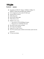
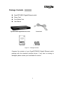
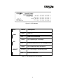
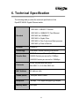
DynaGST/2402G
24 Port 10/100/1000Base-T Gigabit Ethernet
Switch with two SFP (mini) GBIC Slots
PN:
GEP-33224T-1
USER’S MANUAL
Content
1. Introduction .............................................................. 1
Features ..................................................................... 2
Package Contents...................................................... 3
2. Hardware Description ............................................. 5
Front Panel................................................................. 5
Rear Panel ................................................................. 6
LED Indicators............................................................ 6
3. Installation ................................................................ 9
4. Network Application .............................................. 10
5. Troubleshooting .................................................... 11
6. Technical Specification......................................... 13
7. Related Products ................................................... 14
1. Introduction
Gigabit Ethernet over copper technology is a proven cost-effective way for
network equipment to be upgraded from Fast Ethernet to Gigabit speeds.
Standard 4-pair Category 5e/6 copper cabling eliminates the need for
expensive fiber optic cabling for Gigabit speeds. This technology creates
high-speed backbone connections between switches, servers, databases,
and workstations.
The DynaGST/2402G Gigabit Ethernet switch is an ideal solution for solving
traffic congestion at the core of the network. It offers auto-negotiation
10/100/1000Base-T Gigabit Ethernet ports that can significantly improve
your network backbone performance. It will also fit into any enterprise level
network as an exit to the backbone switch. The DynaGST/2402G provides
two mini GBIC Gigabit slots for Gigabit speed network connection.
The DynaGST/2402G Gigabit Ethernet switch features Auto MDI/MDIX
function for each port and features a store-and-forward switching. It autolearns and stores source address on an 8K MAC address table.
1
Features
Compatible with IEEE 802.3 10Base-T, IEEE802.3u 100Base-TX,
IEEE802.3z Gigabit fiber and IEEE802.3ab 1000Base-T
24 Port Gigabit switch with two Mini SFP GBIC ports
Automatic MDIX for all ports
48Gbps Back plane
8K entry MAC address table
500byte Memory buffer
IEEE802.3x flow control:
Pause frame for 10/100/1000Mbps full duplex
Backpressure for 10/100 Mbps half duplex
Store-and-Forward architecture support
10K Jumbo Frame supported
Support 802.1p Class of Service
One DC fan provides proper ventilation and increases system heat sink
performance
19" Rack mount design
2
Package Contents
DynaGST/2402G Gigabit Ethernet switch
Power Cord
Four Rubber Feet
User Manual
DynaGST/2402G Gigabit Ethernet switch
Power Cord
User Guide
Rubber Feet
Figure 1-1. Package Contents
Compare the contents of your DynaGST/2402G Gigabit Ethernet switch
package with the standard checklist above. If any item is missing or
damaged, please contact your local dealer for service.
3
4
2. Hardware Description
This Section describes the hardware of the DynaGST/2402G Gigabit
Ethernet switch.
The physical dimensions of the DynaGST/2402G Gigabit Ethernet switch is:
440 x 161 x 44 mm (W x D x H)
Front Panel
The Front Panel of the DynaGST/2402G Gigabit Ethernet switch consists of
twenty four (24) auto-negotiation 10/100/1000Mbps Ethernet RJ-45
connectors (with Automatic MDI/MDIX support), two Mini GBIC slots, and
LED indicators (1000, Link/Activity, Full duplex/Collision) for each Gigabit
port and power for the unit.
Figure 2-1. The Front Panel of the DynaGST/2402G Gigabit Ethernet switch
RJ-45 Ports (Auto MDI/MDIX): Twenty-four (24) auto-negotiation
10/100/1000 Mbps Ethernet RJ-45 connectors
Mini GBIC ports: Ports 23 and 24 auto-detect between the Gigabit
copper ports and the Mini GBIC (Gigabit fiber) ports. They support 3.3V
Mini SFP GBIC modules. These modules are optional. There are two
LED indicators for the Mini GBIC ports – LNK and ACT. If a Mini GBIC
module is not installed, ports 23 and 24 operate in Gigabit copper mode
only.
[Note] When the Mini GBIC module is installed, the Mini GBIC (Gigabit
fiber) ports have higher priority than the Gigabit copper ports and supercede
5
them. It doesn’t matter if the Gigabit copper port is connected before or after
the Mini GBIC port is connected. The Mini GBIC port always has higher
priority for connection. When the Mini GBIC port is connected, the Gigabit
copper ports are disabled.
Rear Panel
The 3-pronged power plug, on/off switch, and Ventilation fan are located at
the rear Panel of the DynaGST/2402G Gigabit Ethernet switch as shown in
Figure 2-2. The Switch will work with AC in the range 100-240V AC, 5060Hz.
Figure 2-2. Rear panel of the DynaGST/2402G Gigabit Ethernet switch
LED Indicators
The LED Indicators give a real-time indication of system operating status.
There are three LED-indicators (1000, LNK/ACT) for each Gigabit port and
one Power LED for the entire unit. The following table provides descriptions
of LED status.
6
Figure 2-3. LED Indicators
LED
Status
Description
Green
Power On
Off
Power is not connected
Green
Port is operating at 1000Mbps.
Off
No device attached or in 10/100Mbps mode
Green
Port is connecting with the device.
Blinking
Port is receiving or transmitting data.
Off
No device attached.
Power
1000
LNK/ACT
Table 2-1. The Descriptions of LED Indicators
7
Mini GBIC LED
Each Mini GBIC port has an LED indicator – LNK /ACT. The following table
provides descriptions of LED status.
Figure 2-4. Mini GBIC Port LED Indicators
LED
LNK/ ACT
Status
Description
Green
The port is connecting with device
Blinking
The port is transmitting or receiving the data
Off
No data transmitting or receiving or No
device attached
Table 2-2. The Descriptions of Mini GBIC LED Indicators
8
3. Installation
Set the Switch on a sufficiently large flat space with a power outlet nearby.
The surface should be clean, smooth, level, and sturdy. Ensure there is
enough clearance around the Switch to allow air circulation and the
attachment of the power cord and cables.
Attaching Rubber Feet
Make sure mounting surface on the bottom of the Switch is grease and
dust free.
Remove adhesive backing from your Rubber Feet.
Apply the Rubber Feet to each corner on the bottom of the Switch.
These footpads protect the Switch from shock and vibration.
Power On
Connect the power adapter cable to the power socket on the rear panel of
the Switch. The other end of the power cord connects to the power outlet.
Check the power indicator on the front panel to make sure if power is
properly supplied.
9
4. Network Application
This section provides a sample of network topology in which the
DynaGST/2402G is used. In general, the DynaGST/2402G Gigabit Ethernet
switch is designed as a high-bandwidth backbone switch.
You can use the DynaGST/2402G to connect servers, switches,
workstations, and PCs to each other by connecting these devices directly to
the Switch. The Switch automatically learns node addresses, which are
subsequently used to filter and forward all traffic based on the destination
address. The Gigabit fiber port is designed to connect the Ethernet network
with a fiber network.
For enterprise networks where large data broadcasts are constantly
processed, this switch is an ideal link between departmental switches and
the core switch. All workstations can connect to departmental switches and
those switches are then connected to the DynaGST/2402G Gigabit Ethernet
switch. Now all the devices in this network can communicate with each
other. Connecting servers to the core switch is important because it allows
each workstation to access the server’s data.
This switch is a perfect for backbone connectivity.
10
5. Troubleshooting
The Switch can be easily monitored through panel indicators to assist in
identifying problems. This section describes common problems you may
encounter and where you can find possible solutions.
Diagnosing LED Indicator
If the Link indicator does not light up after connection, check whether the
network interface (e.g., a network adapter card on the attached device),
network cable, or switch port is defective. Verify that the switch and attached
device are powered on. Ensure the cable is plugged into both the switch and
corresponding device. Verify the proper cable type is used and its length
does not exceed specified limits.
Power
If the power indicator does turn on when the power cord is plugged in, you
may have a problem with power outlet or power cord. However, if the Switch
powers off after running for a while check for loose power connections, local
power losses, or surges at power outlet. If you still cannot resolve the
problem, contact your local dealer for assistance.
Transmission Mode
Each port will automatically set to the same transmission mode used by the
attached device (i.e., half or full duplex). The RJ-45 ports use autonegotiation to set the transmission mode. If the attached device does not
support auto-negotiation then this switch will default to the lowest common
speed.
11
Cabling
RJ-45 ports: Use unshielded twisted-pair (UTP) or shield twisted-pair (STP)
cable for RJ-45 connections: 100m. of Category 3,5e, or 6 cable for 10Mbps
connections, 100m. of Category 5e/6 cable for 100Mbps connections , or
100m. of 4-pair Category 5e/6 copper cabling for 1000Mbps connection.
Also be sure that the length of any twisted-pair connection does not exceed
100 meters (328 feet).
12
6. Technical Specification
The following table provides the technical specification of the
DynaGST/2402G Gigabit Ethernet switch.
IEEE 802.3 10BASE-T Ethernet
IEEE 802.3u 100BASE-TX Fast Ethernet
Standard
IEEE 802.3ab 1000Base-T
IEEE 802.3z Gigabit Fiber
IEEE 802.3x Flow Control and Back-pressure
IEEE 802.1p Class of Service
Protocol
CSMA/CD
Technology
Store-and-Forward switching architecture
14880 Packets per Second for 10Mbps
Transfer Rate
148800 Packets per second for 100Mbps
1488000 Packets per second for 1000Mbps
Connector
RJ-45: 24 ports with Auto-MDIX
Mini GBIC: 2 x 3.3V Mini GBIC slot
MAC Address
8K address table
Jumbo packet
10Kbytes Jumbo Packet
Backplane
48Gbps, 71.42 Mpps throughput @ 64bytes
Memory Buffer
500 bytes
13
10Base-T:
2 pairs UTP/STP CAT. 3/4/5 cable
EIA/TIA 568 100 Ohm (up to 100m)
Network Cable
100Base-TX: 2 pairs UTP/STP CAT. 5/5e cable
EIA/TIA 568 100Ohm (up to 100m)
Gigabit Copper: 4 pairs UTP/STP CAT. 5e/6 cable
EIA/TIA 568 100Ohm (up to 100m)
Per RJ-45 port: 1000 (green)
LED
Link/Activity (Green)
Per MINI GBIC: Link/Activity (Green)
Per unit:
Power Supply
Power
Consumption
Operation
Temperature
Operation
Humidity
Dimension
EMI & Safety
Power
Internal power supply, AC 100~240VAC, 50/60 Hz
26.5 Watts (Maximum)
0˚ to 45˚C (32˚ to 113˚ F)
10% to 90% (Non-condensing)
440mm x 161mm x 44mm (W x D x H)
17.3" x 6.34" x 1.73"
FCC Class A, CE, UL, cUL
7. Related Products
GEP-22000S-L
SFP (mini) GBIC Transceiver, 1000SX (LC/MM/500m)
GEP-22100L-L
SFP (mini) GBIC Transceiver, 1000LX (LC/SM/10Km)
14
908 Canada Court
City of Industry, CA 91748 U.S.A.
Phone: 626.964.7873 or 800.346.6668 Fax: 626.964.7880
www.unicomlink.com
UNIDOC021005
rev.071306
e-mail: [email protected]