1
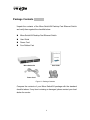
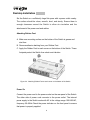
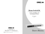
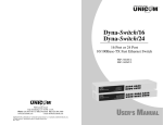
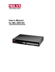
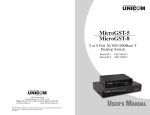
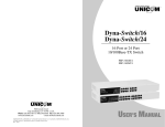
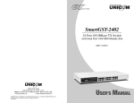
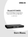
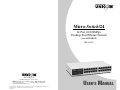
Micro-Switch/24
24 Port 10/100Mbps
Desktop Fast Ethernet Switch
(Auto MDI/MDIX)
FEP-32024T
908 Canada Court
City of Industry, CA 91748 U.S.A.
Phone: 626.964.7873 or 800.346.6668 Fax: 626.964.7880
www.unicomlink.com
www.unihomenetworkingbox.com
e-mail: [email protected]
©UNICOM 2005. UNICOM and “A Network Systems Solution” are trademarks of UNICOM Electric, Inc.
All rights reserved. Specifications subject to change without notice.
Rev: 01.05
USER’S MANUAL
Content
1. Introduction .............................................................. 1
Features ...................................................................... 1
Package Contents...................................................... 2
Ethernet Switching Technology............................... 3
2. Hardware Description.............................................. 4
Front Panel ................................................................. 4
LED Indicators............................................................ 4
Rear Panel................................................................... 5
Desktop Installation................................................... 6
3. Network Application ................................................ 7
4. Troubleshooting..................................................... 10
5. Technical Specification ......................................... 12
1. Introduction
The 24 Port Micro-Switch/24 Desktop Fast Ethernet Switch is a multi-port
Switch that can be used to build high-performance switched workgroup
networks. This switch is a store-and-forward device that offers low latency
for high-speed networking. It is targeted at workgroup, department, or
backbone computing environments in SME (small, medium enterprise)
businesses.
The Micro-Switch/24 features a “store-and-forward “switching scheme. This
allows the switch to auto-learn and store source addresses on a 4K-entry
MAC address table.
Features
Conforms to IEEE 802.3, 802.3u and 802.3x
Twenty-four (24) 10/100 Base-TX RJ-45 Ethernet ports
Auto-MDIX on all ports
IEEE 802.3x flow control support
Flow control on full-duplex
Back pressure on half-duplex
N-Way Auto-Negotiation supported
Store-and-Forward switching architecture and no-blocking full wire
speed
Back plane Bandwidth 4.8 Gbps)
Embedded 1.25Mbits memory buffer
4K MAC address table
Compact 10” size
1
Package Contents
Unpack the contents of the Micro-Switch/24 Desktop Fast Ethernet Switch
and verify them against the checklist below.
Micro-Switch/24 Desktop Fast Ethernet Switch
User Guide
Power Cord
Four Rubber Feet
Micro-Switch/24
User Guide
Power Cord
Rubber Feet
Figure 1-2. Package Contents
Compare the contents of your Micro-Switch/24 package with the standard
checklist above. If any item is missing or damaged, please contact your local
dealer for service.
2
Ethernet Switching Technology
Ethernet Switching Technology dramatically boosted the total bandwidth of a
network, eliminated congestion problems inherent with Carrier Sense
multiple access with Collision Detection (CSMA/CD) protocol, and greatly
reduced unnecessary transmissions.
This revolutionized networking in a number of ways. First, by allowing twoway, simultaneous transmissions over the same port (Full-duplex) which
essentially doubled the bandwidth. Second, by reducing the collision domain
to a single switch-port which eliminated the need for carrier sensing. Third,
by using the store-and-forward technology’s approach of inspecting each
packet to intercept corrupt or redundant data and switching eliminated,
unnecessary transmissions that slow the network. Also employing an
address learning function, Ethernet replaced inefficient receiving ports.
Auto-negotiation regulates the speed and duplex of each port, based on the
capability of both devices. Flow-control allows transmission from a 100Mbps
node to a 10Mbps node without loss of data. Auto-negotiation and flowcontrol may require disablement of some networking operations that involve
legacy equipment. Disabling the auto-negotiation is accomplished by
manually setting the speed or duplex of a port.
Ethernet Switching Technology supplied higher performance at costs lower
than other solutions. Wider bandwidth, no congestion, and the reduction in
traffic is why switching is replacing expensive routers and inefficient hubs as
the ultimate networking solution. Switching brought a whole new way of
thinking to networking.
3
2. Hardware Description
This Section describes the hardware of the Micro-Switch/24 Desktop Fast
Ethernet Switch/.
The physical dimensions of the Micro-Switch/24 are: 250mmx 133 mm x
37mm (L x W x H)
Front Panel
The Front Panel of the Micro-Switch/24 consists of twenty-four (24)
10/100Base-TX RJ-45 ports. The LED Indicators are also located on the
front panel of the Switch.
Figure 2-1. The Front panel
RJ-45 ports (Auto MDI/MDIX): Twenty-four (24) 10/100Mbps auto-sensing
ports for 10Base-T or 100Base-TX device connection.
[Auto MDI/MDIX means that you can connect to another switch or
workstation with either straight-through or crossover cabling.]
LED Indicators
The LED Indicators gives real-time information of systematic operation
status. The following table provides descriptions of LED status.
4
Figure 2-2. LED Indicators
LED
Power
LK/ACT
Status
Description
Green
Power is supplied
Off
Power is not connected
Green
The port is connecting with the device
Blinks
The port is receiving or transmitting data
Off
No device attached
Table 2-1.
Descriptions of LED Indicators
Rear Panel
The 3-pronged power plug is located at the rear panel of the Micro-Switch/24
as shown in Figure 2-3. The Switch will work with AC in the range 100-240V
AC, 50-60Hz.
Figure 2-3. The Rear Panel of the Micro-Switch/24
5
Desktop Installation
Set the Switch on a sufficiently large flat space with a power outlet nearby.
The surface should be clean, smooth, level, and sturdy. Ensure there is
enough clearance around the Switch to allow air circulation and the
attachment of the power cord and cables.
Attaching Rubber Feet
A. Make sure mounting surface on the bottom of the Switch is grease and
dust free.
B. Remove adhesive backing from your Rubber Feet.
C. Apply the Rubber Feet to each corner on the bottom of the Switch. These
footpads protect the Switch from shock and vibration.
Figure 2-4. Attaching Rubber Feet to each corner on the bottom of the Switch
Power On
Connect the power cord to the power socket on the rear panel of the Switch.
The other side of power cord connects to the power outlet. The internal
power supply in the Switch works with AC in the voltage range 100-240VAC,
frequency 50~60Hz.Check the power indicator on the front panel to ensure
that power is properly supplied.
6
3.Network Application
This section provides a few samples of network topology in which the Switch
is used. In general, the Micro-Switch/24 Desktop Fast Ethernet Switch is
designed as a segment switch. That is, with its large address table (4K MAC
address) and high performance, it is ideal for interconnecting networking
segments.
You can also use the Micro-Switch/24 to connect PCs, workstations, and
servers to each other by connecting these devices directly to the Switch. The
switch automatically learns node addresses, which are subsequently used to
filter and forward all traffic based on the destination address. The Switch can
connect with another switch or hub to interconnect each of your small,
switched workgroups to form a larger switched network.
Small Workgroup
The Micro-Switch/24 can be used as a standalone switch to which personal
computers, servers, and printer servers are directly connected to form a
small workgroup.
Figure 3-1. Small Workgroup Application
7
Segment Bridge
For enterprise networks where large data broadcasts are constantly
processed, this switch is an ideal solution for department users to connect to
the corporate backbone.
In the illustration below, two Ethernet switches with PCs, a print server, and
a local server are both connected to the Micro-Switch/24. All devices in this
network can then communicate with each other through the Micro-Switch/24.
Connecting servers to the Switch allow other users to access the server’s
data.
Figure 3-2 Department Bridge Application
8
4.Troubleshooting
This section is intended to help you solve the most common problems on
the Micro-Switch/24
Incorrect connections
Faulty or loose cables
Look for loose or obviously faulty connections. If they appear to be OK,
make sure the connections are snug. If this does not correct the
problem, try a different cable.
Non-standard cables
Non-standard and miswired cables may cause numerous network
collisions and other network problems that can seriously impair
network performance. A Category 5 cable tester is a recommended
tool for every 100Base-T network installation.
Improper Network Topologies
It is important to make sure that you have a valid network topology.
Common topology faults include excessive cable length and too many
repeaters (hubs) between end nodes. In addition, you should make
sure that your network topology contains no data path loops. Between
any two end nodes, there should be only one active cabling path at
any given time. Data path loops will cause broadcast storms that will
severely impact your network performance.
9
Diagnosing LED Indicators
The Switch can be easily monitored through panel indicators to assist
in identifying common problems you may encounter and where you
can find possible solutions.
If the power indicator does not turn on when the power cord is plugged
in, you may have a problem with power cord. Than check for loose
power connections, power losses, or surges at power outlet. If you still
cannot resolve the problem, contact your local dealer for assistance.
Cabling
RJ-45 ports: Use unshielded twisted-pair (UTP) or shielded twistedpair ( STP ) cable for RJ-45 connections: 100m. Category 3, 4, or 5
cable for 10Mbps connections or 100m. Category 5/5e cable for
100Mbps connections. Also be sure that the length of any twisted-pair
connection does not exceed 100 meters ( 328 feet ).
10
5.Technical Specification
Standard
IEEE 802.3 10Base-T Ethernet,
IEEE 802.3u 100Base-TX Fast Ethernet
IEEE802.3x Flow Control and Back-pressure
Protocol
CSMA/CD
Technology
Store and Forward switching architecture
Transfer Rate
14,880 pps Ethernet port
148,800 pps Fast Ethernet port
MAC address
4K Mac address table
Memory Buffer
1.25Mbits
10Base-T: 2-pair UTP/STP Cat. 3/4/5 cable
Network Cable
EIA/TIA-568 100-ohm (up to 100m)
100Base-TX: 2-pair UTP/STP Cat. 5/5e cable
EIA/TIA-568 100-ohm (up to 100m)
LED Indicators
Back-plane
Dimensions
Per port: Link/Activity
Per unit: Power
4.8Gbps
250mmx 133 mm x 37mm (L x W x H)
9.85" x 4.45" x1.46"
Operational Temp.
O˚ to 45˚ C (32˚ to 113˚ F)
Operational
Humidity
10% to 90% (Non-condensing)
Power Supply
100-240 VAC, 50~60Hz
11
Power
Consumption
EMI
19 Watts (maximum)
FCC Class A, CE
12