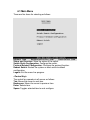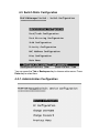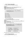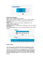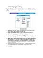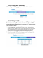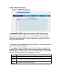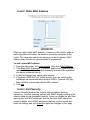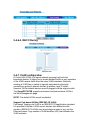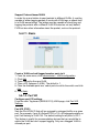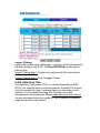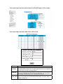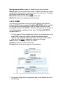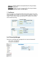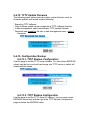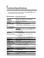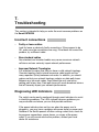
1
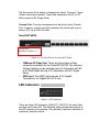
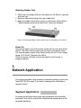
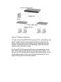
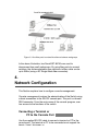
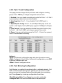
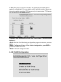
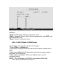
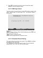
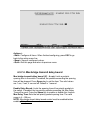
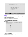
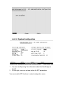
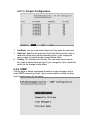
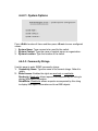
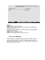
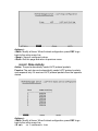
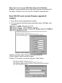
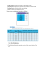
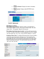
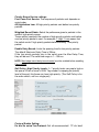
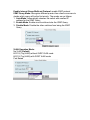
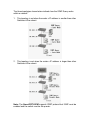
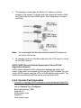
SmartGST-801M
8 Port 100Base-FX Managed Switch
with VLAN and GBIC slot
GEP-62108F-C
GEP-62108F-T
GEP-62108F-C-SM
908 Canada Court
City of Industry, CA 91748 U.S.A.
Phone: 626.964.7873 or 800.346.6668 Fax: 626.964.7880
www.unicomlink.com
e-mail: [email protected]
©UNICOM 2004. UNICOM and “A Network Systems Solution” are trademarks of UNICOM Electric, Inc.
All rights reserved. Specifications subject to change without notice.
Rev: 8.04
USER’S MANUAL
1.
Introduction
The 8 Port SmartGST-801M is a high-speed, professional-grade Fast
Ethernet switch that provides wire-speed, a Fast Ethernet switching
technology that allows high-performance, low-cost connections up to
Full-Duplex, 100Mbps Ethernet networks. The built-in GBIC slot
allows for optional GBIC adapter, creating the perfect, flexible
backbone switch. This switch also features integrated VLAN functions
to improve network speed and security. Functions include Per-Port
Grouping and Priority Modes.
Figure 1-1. The SmartGST-801M
Features
n
n
n
n
n
n
n
n
n
n
n
n
n
All nine ports can operate simultaneously
Eight dual SC fiber ports available in single-mode and multimode
The GBIC Slot accommodates Unicom GBIC adapters
One front side Console Port for switch configuration
VLAN supports up to 25 groups
Store-and-Forward switching architecture
2Mb Memory Buffer Sharing
Back-pressure for Half-duplex. Pause frame for Full-duplex
Plug-and-Play configuration auto address learning
Embedded 8K-entry MAC address table
LED indicators for Power, LNK/ACT, FDX/COL
Compliant with IEEE 802.3, 802.3u and 802.3x standards
19 Rack-mountable
Intelligent Management Features
n
n
n
n
n
n
n
n
n
n
Web-based management
SNMP network management
Console and Telnet management
Port Base VLAN and IEEE 802.1q Tag VLAN. up to 256
VLAN groups, VLAN IDs up to 4K
IEEE 802.3 ad port trunk with LACP (Link Aggregation
Control protocol) supported
IEEE 802.1d Spanning Tree
MIB II (RFC 1213) supported
IP Multi-cast, IGMP Snooping (up to 256 IGMP groups)
Support Quality of Service (system provides 8 levels) and
Class of service (per port Hi/Low Queue)
Port Mirror, Broadcast Filter, Static MAC Address filtering,
Port Security, and GVRP supported
Package Contents
Unpack the contents of the SmartGST-801M and verify them against
the checklist below.
n
n
n
n
n
SmartGST-801M Switch
Power Cord
Four Rubber Feet
RS-232 cable
User Guide (CD Manual)
SmartGST-801M
Rubber Feet
RS-232 cable
Figure 1-2. Package Contents
Power Cord
User Guide
Compare the contents of your SmartGST-801M package with the
checklist above. If any item is missing or damaged, please contact
your local dealer or reseller for service.
Ethernet Switching Technology
Ethernet Switching Technology dramatically boosted the total
bandwidth of a network, eliminated congestion problems, and greatly
reduced unnecessary transmissions.
This revolutionized networking by allowing two-way, simultaneous
transmissions over the same port (Full-duplex) that essentially
doubled the bandwidth. Secondly, it reduced the collision domain to a
single switch-port that eliminated the need for carrier sensing.
This technology also uses a store-and-forward technology approach
of inspecting each packet to intercept corrupt or redundant data,
eliminating unnecessary transmissions that slow the network.
Ethernet Switching Technology supplies higher performance at lower
costs than other solutions. Due to wider bandwidth, no congestion,
and the reduction in traffic, switching is replacing expensive routers
and inefficient hubs as the ultimate networking solution.
Management Methods
The SmartGST-801M supports the following management methods:
n
n
n
Console and Telnet Management
Web-based Management
SNMP Network Management
Console and Telnet Management
Console Management is done through the RS-232 Console Port.
Managing the SmartGST-801M with this method requires a direct
connection between a PC and the switch. Telnet management is
done over a network. Once the SmartGST-801M is on the network,
you can use Telnet to Log in and change the configuration.
Web-based Management
This switch provides an embedded HTML web site residing in flash
memory. It offers advanced management features and allows users
to manage the SmartGST-801M from anywhere on the network
through a standard browser such as Microsoft Internet Explorer.
SNMP Network Management
SNMP (Simple Network Management Protocol) provides
monitoring and control of network devices. It manages
configurations, statistic collection, performance, and security.
2.
Hardware Description
This section describes the switch hardware. The SmartGST-801M is
a 19" rack mountable switch with eight 100Mbps Fiber ports and one
GBIC port
The physical dimensions of the SmartGST-801M are:
440mm x 160mm x 44mm (L x W x H)
Front Panel
The Front Panel of the SmartGST-801M consists of eight 100Mbps
Fast Ethernet Fiber and one GBIC port. LED indicators are located on
the front panel of the switch.
Figure 2-1. The Front Panel of theSmartGST-801M
The front panel of the switch is displayed as below. There are 2 types
of fiber connectors available. These fiber connectors are SC or ST
Multi-mode and SC Single Mode.
Console Port: Console management can be done via the Console
Port. It requires a direct connection between the switch and an end
station (PC) via an RS-232 cable.
SmartGST-801M
Console Port
Baud Rate: 9600,N, 8,1
Figure 2-2. The Front Panel of the SmartGST-801M
n
n
100Base-FX Fiber Port: There are three types of fiber
connectors available for the SmartGST-801M. The distance
for fiber cabling can be extended up to 2 kilometers with SC
or ST Multi-Mode and up to 30 kilometers with SC Single
Mode.
GBIC port: This GBIC slot supports 3.3V Gigabit
Transceivers for Gigabit SX or LX only.
LED Indicators
Figure 2-3. LED Indicators
There are three LED Indicators (LNK/ACT, FDX/COL) for each Fiber
port and one Power LED. The following table provides descriptions of
the LED statuses and meaning. They provide a real-time indication of
systematic operation status.
LED Status Color
Power
LNK /
ACT
On
Green Power On
On
Green
Blinks
The port is successfully connecting with
the device on 100Mbps.
The port is receiving or transmitting
Green
data.
Off
No device attached.
On
FDX /
COL
Description
Orange
Blinks
The port is operating in Full-duplex
mode and device is attached.
Orange Collision of Packets occurs in the port.
Half-duplex mode or no device
attached.
Off
Table 2-1. The description of LED Indicators
Rear Panel
The Console port and 3-pronged power plug is located at the Rear
Panel of the SmartGST-801M as shown in Figure 2-7. The Switches
will work with AC in the range 100-240V AC, 50-60Hz.
Power on/off switch
AC Power Plug Socket
Figure 2-7 The Rear Panel of the SmartGST-801M
Desktop Installation
Set the switch on a sufficiently large flat space with a power outlet
nearby. The surface where you put your Switch should be clean,
smooth, level, and sturdy.
Make sure there is enough clearance around the Switch to allow
attachment of cables, power cord and air circulation.
Attaching Rubber Feet
1. Make sure mounting surface on the bottom of the Switch is grease
and dust free.
2. Remove adhesive backing from your rubber feet.
3. Apply the rubber feet to each corner on the bottom of the Switch.
These footpads prevent the switch from shock and vibration.
Figure 2-8. Attaching Rubber Feet to each corner on the bottom of the Switch
Power On
Connect the power cord to the power socket on the rear panel of the
Switch. The other side of power cord connects to the power outlet.
The internal power supply in the Switch works with AC in the voltage
range 100-240VAC, frequency 50~60Hz.
Check the power indicator on the front panel to see if power is
properly supplied.
3.
Network Application
This section provides a few samples of network topology in which the
SmartGST-801M is used. This switch is designed as a desktop or
segment switch.
Segment Application
In enterprise networks where large data broadcasts are constantly
processed, this switch is perfect for departmental connections to the
corporate backbone.
Figure 3-2 Segment Application
You can use the SmartGST-801M to connect PCs, workstations, and
servers to each other by connecting these devices directly to the
Switch. All the devices in this network can communicate with one
another. Connecting servers to the backbone switch allows other
users to access the server s data.
The SmartGST-801M automatically learns node addresses, which
filter, and forward all traffic based on the destination address. You
can use any of the Fiber ports to connect with another switch or hub
to interconnect each of your small switched workgroups to form a
larger and long distance switched network.
Figure 3-3 Use fiber ports to extend the distance between workgroups
In the above illustration, two SmartGST-801Ms are used to
interconnect two small workgroups. By using fiber ports to connect
switches, the distance between two switches via fiber cable can be
up to 30Km (using a SC Single Mode fiber connector).
4.
Network Configuration
This Section explains how to configure console management.
Console management involves the administration of the Switch using
a direct connection to the RS-232 console port. This port is a female
DB-9 connector. From the main menu of the console program, user
has access to the functions of the switch.
Connecting a Terminal or
PC to the Console Port
Use the supplied RS-232 cable to connect a terminal or PC to the
console port. The terminal or PC to be connected must support the
termin l emul tion progr m
After the connection between Switch and PC is finished, turn on the
PC and run a terminal emulation program or Hyper Terminal to
match the following default characteristics of the console port:
Baud Rate: 9600 bps
Data Bits: 8
Parity: none
Stop Bit: 1
Control flow: None
Figure 4-1.
The settings of communication parameters
After you have finished parameter settings, press Enter Key and
the Main Menu of console management appears.
Console — Menu
1. The switch provides a serial interface to manage and monitor the
switch. Users can link to the switch through the Console Port using
Windows HyperTerminal program.
2. Type user name and password to login. The default user name is
root . The default password is root .
4-1 Main Menu
There are five items for selecting as follows:
Status and Counters: Show the status of the switch.
Switch Static Configuration: Configure the switch.
Protocol Related Configuration: Configure the protocol function.
Reboot Switch: Restart the system or reset switch to default
configuration.
Logout: Exit the menu line program.
<Control Key>
The control key operates in all menus as follows:
Tab: Moves the cursor to next item.
Backspace: Moves the cursor to previous item.
Enter: Selects item.
Space: Toggles selected item to next configure.
4-2. Status and Counters
You can press the key of Tab or Backspace to choose item, and press
Enter key to select item.
4-2-1. Port Status
This page displays each port’s status
Type: Displays the port type.
Enabled: Displays whether port is enabled or disable depending on user
setting. Enabled will be displayed Yes , disabled will be displayed No .
Status: Displays whether the port is linked or not linked. Down is not
linked and Up is linked.
Mode: Displays the port speed and duplex function.
Flowtrl: Displays whether Flow Control is enabled or disabled.
Actions->
You can press the Tab or Backspace key to choose action menu. Press
Enter key to select item
<Quit>: Exits the port status page and returns to previous menu.
4-2-2. Port Counters
The following information provides a view of the current status of the unit.
Actions->
You can press the Tab or Backspace key to choose action menu. Press
Enter key to select item
<Quit>: Exits the port status
<Reset All>: Sets all counts to 0.
4-2-3. System Information
System Description: Displays the name of device.
MAC Address: The unique hardware address assigned by manufacturer.
Firmware Version: Displays the switch s firmware version.
Hardware Version: Displays the switch s Hardware version.
Kernel version: Displays "write to default EEPROM value" version.
4-3. Switch Static Configuration
You can press the Tab or Backspace key to choose action menu. Press
Enter key to select item
4-3-1. Administration Configuration
4-3-1-1. Device Information
This page provides device configuration information.
Actions->
<Edit>: Configures all items. When finished configuration, press
Backspace to go back to the action menu line.
<Save>: Saves all configured values.
<Quit>: Exits the Device Information Page and returns to previous menu.
4-3-1-2. IP Configuration
User can configure the IP setting and fill in the new value.
Actions->
<Edit>: Configure all items. When finished configuration, press ESC to go
back to action menu line.
<Save>: Saves all configured values.
<Quit>: Exit the IP configuration page and return to previous menu.
Note: Always restart the computer after finishing the setup.
4-3-1-3. Change Username
User can change Web Management user name.
4-3-1-4. Change Password
User can change Web Management user password. The default
password is root
4-3-2. Port / Trunk Configuration
This page provides changes to all port status and configures trunking
groups. Press TAB key to change configuration of each item.
1. Enabled: User can disable or enable port control for Ports 1 ~ 8. Port 9
is permanently enabled and cannot be disabled.
2. Auto Negotiate: Ports 1 ~ 9 are disabled: Port 9 (GBIC port) is
enabled.
3. Speed/Duplex Config: Ports 1 ~ 8 (100 Mbps Fiber port) can be set
as Full or Half duplex; Port 9 (GBIC port) supports 1000Mbps Full Duplex
only.
4. Flow Control: Users can enable or disable flow control function (only
for Ports 1 ~ 8); Port 9 (GBIC port) always supports flow control.
5. Group: User can set trunking groups for Port 1 ~ 8 (up to four groups).
Port 9 is not available for trunking.
Actions->
<Quit>: Exit the port configuration page and return to previous menu.
<Edit>: Configure all items. When finished with configuration, press ESC
to go back to action menu line.
<Save>: Save all configured values.
4-3-3. Port Mirroring Configuration
Port Mirroring is a method of monitoring traffic in switched networks. Port
traffic can be monitored through one specific port. For instance, traffic
going in and out of monitored ports will be duplicated into a monitoring
port. Press Space key to change configuration of each item.
1.Port Mirroring State: Press Space key to enable and disable.
2.Analysis Port: Port used to monitor traffic on a specific port.
3. Port: The ports you want to monitor. All monitored port traffic will be
copied to a single port. You can select up to 9 ports to monitor. Users can
choose to monitor receiving (RX) frames only or transmission (TX) frames
only or both from the Action column.
Actions->
<Quit>: Exit the Port Monitoring configuration page and return to previous
menu.
<Edit>: Configures all items. When finished configuration, press ESC to
go back to action menu line.
<Save>: Save all configured value.
4-3-4. VLAN Configuration
4-3-4-1. VLAN Configuration
1. PVID (Port VID): Sets the VLAN port ID that will be assigned to
untagged traffic on a given port. This feature is useful for accommodating
devices that you want to participate in the VLAN but don t support
tagging. Only one untagged VLAN is allowed per port.
2. Ingress Filter 1: It matches the web Ingress Filtering Rule 1. It
forwards only packets with VIDs matching this port s configured VID.
Press Space key to forward or drop the frames whose VIDs do not match
this port s VID.
3. Ingress Filter 2: It matches the web Ingress Filtering Rule 2. It drops
untagged frames.
Press Space key to drop or forward untagged frames.
4-3-4-2. Create a VLAN Group
Create a VLAN and add tagged /untagged member ports to it.
1. VLAN Name: Type a name for the new VLAN.
2. VLAN ID: Type a VID (between 1 ~ 4094). The default is 1.
3. Protocol VLAN: Press Space key to choose protocol type.
4. Mode: Press Space key to choose VLAN member. There are three
types: 802.1Q, 802.1Q with GVRP, and Port Base.
UnTagged: the member port is an untagged port.
Tagged: the member port is a tagged port.
NO: The port is not member of this VLAN group.
Actions->
<Quit>: Exit this page and return to previous menu.
<Edit>: Configure all items. When finished configuration, press ESC to go
back action menu line.
<Save>: Save all configured values.
4-3-4-3. Edit / Delete a VLAN Group
On this page, user can edit or delete a VLAN group.
1.Press <Edit> or <Delete> item.
2.Choose the VLAN group that you want to edit or delete and then press
enter.
3.Users can modify the VLAN item protocol and remove some member
ports from this VLAN group.
4.After editing or deleting a VLAN, press <Save> key to save all
configured values.
NOTE: 1.The VLAN Name and VLAN ID cannot be modified here.
2.The default VLAN cannot be deleted.
4-3-5. Priority Configuration
1.There are 7 priority levels (0 ~ 7) to map to high or low queue.
2.High/Low Queue Service Ration H/L: Users can select the ratio of
high priority packets to low priority packets.
Actions->
<Edit>: Configures all items. When finished with configuration. Press
ESC to go back to action menu line.
<Save>: Save all configure values.
<Quit>: Exit this page and return to previous menu.
High Low Queue service ratio: 1:1, 2:1, 3:1, 4:1, 5:1, 6:1, 7:1, FIFO,
HŁ L
First In First Out (FIFO): The sequence of packets sent depends on
arrival order.
Ł L): All high priority packets are sent before low priority
High to Low (HŁ
packets
Ratio (1:1, 2:1, 3:1, 4:1, 5:1, 6:1, 7:1): Select the preference given to
packets in the switch’s high-priority queue.
These options represent the number of high priority packets sent before
one low priority packet is sent. For example, 2 High: 1 Low means that
the switch sends 2 high priority packets before sending 1 low priority
packet.
4-3-6. MAC Address Configuration
4-3-6-1. Static MAC Address
When you add a static MAC address, it remains in the switch’s address
table regardless of whether the device is physically connected to the
switch. This saves the switch from having to re-learn a device’s MAC
address when it is reconnected or active on the network again.
In this page user can add, modify, or delete a static MAC address.
Add static MAC address
1. Press <Add> --> <Edit> key to add a static MAC or edit an address.
2. Enter the MAC address which the port should permanently forward
traffic to and from, regardless of the device s network activity.
3. In the Port num item, enter the port number.
4. If tag-based (802.1Q) VLAN is set up on the switch, static addresses
are associated with individual VLANs. Type the VID to associate with
the MAC address.
5. Press ESC to go back to the action menu line and then select
<Save> to save all configured values.
Edit static MAC address
1. Press <Edit> key to modify a static MAC address.
2. Choose the MAC address that you want to modify and then press
enter.
3. Press <Edit> key to modify all the items.
4. Press ESC to go back to the action menu line and then select
<Save> to save all configured values.
Delete static MAC address
1. Press <Delete> key to delete a static MAC address.
2. Choose the MAC address that you want to modify and then press
enter.
3. After deleting static MAC address, press <Save> to complete the
deleting operation.
4-3-6-2. Filtering MAC Address
Edit Filtering MAC address
1. Press <Edit> key to modify a static Filtering address.
2. Choose the MAC address that you want to modify and then press
enter.
3. Press <Edit> key to modify all the items.
4. Press ESC to go back to the action menu line and then select
<Save> to save all configured values.
Delete Filtering MAC address
1. Press <Delete> key to delete a Filtering MAC address.
2. Choose the MAC address that you want to delete and then press
enter.
3. After deleting the Filtering MAC address, press <Save> to complete
the operation.
4-3-7. Misc Configuration
4-3-7-1. Port Security
A port in security mode will be locked without address learning
permission. Only the incoming packets with SMAC already existing in the
address table can be forwarded normally. Users can disable the port from
learning any new MAC addresses, then use the static MAC addresses
screen to define a list of MAC addresses that can use the secure port.
1. Press <Edit> to enable or disable the port security.
2 Press Space key to choose Enable / Disable item
3.
Press ESC to go back to the action menu line and then select
<Save> to save all configured values.
4-3-7-2. MAC Age Interval
Type the number of seconds that an inactive MAC address remains in the
switch s address table. The valid range is 300 ~ 765 seconds. Default is
300 seconds.
Actions->
<Edit>: Configure all items. When finished configuring, press ESC to go
back to the action menu line.
<Save>: Save all configured values.
<Quit>: Exit this page and return to previous menu.
4-3-7-3. Broadcast Storm Filtering
This page configures broadcast storm control. Press <Edit> to configure
the broadcast storm filter mode.
Press Space key to choose the threshold value. The valid threshold
values are 5%, 10%, 15%, 20%, 25%, and NO (None).
Actions->
<Edit>: Configure all items. When finished configuring, press ESC to go
back to the action menu line.
<Save>: Save all configured values.
<Quit>: Exit this page and return to previous menu.
4-3-7-4. Max bridge transmit delay bound
Max bridge transmit delay bound (0,1 - 4 sec): Limits a packets
queuing time in the switch. If enabled, the packets exceeding the queuing
time will be dropped. Press Space key to set the time. The valid values
are 1 sec, 2 sec, 4 sec and off. Default is 1 second.
Enable Delay Bound: Limits the queuing time of low priority packets in
the switch. If enabled, the low priority packets exceeding the Max Delay
Time will be sent. Press the Space key to enable or disable this function.
Max Delay Time: Sets the low priority packet queuing time. The valid
range is 0 ~ 255 ms.
NOTE: Max bridge transit delay bound control must be enabled before
enabling Delay Bound.
Actions->
<Edit>: Configure all items. When finished configuring, press ESC to go
back to the action menu line.
<Save>: Save all configured values.
<Quit>: Exit this page and return to previous menu.
4-4. Protocol Related Configuration
4-4-1. STP
4-4-1-1. STP Enable
This page enables or disables the Spanning Tree function. Press Space
key to select enabled or disabled.
4-4-1-2. System Configuration
1.
You can view Spanning Tree information about the Root Bridge on
the left.
2. On the right, users can set new values for STP parameters.
You must enable STP functions to select configuration menu.
4-4-1-3. Perport Configuration
1.
2.
3.
PortState: You can view switch Spanning Tree status for each port.
PathCost: Specifies the path cost of the port that the switch uses to
determine which ports are the forwarding ports. If you change the
value, restart the switch for the change to take effect.
Priority: This indicates Port Priority. You can make a port more or
less likely to become the root port. If you change the value, restart the
switch for the change to take effect.
4-4-2. SNMP
Use this page to define management stations as trap managers and to
enter SNMP community strings. Users can also define a name, location,
and a contact person for the switch.
4-4-2-1. System Options
Press <Edit> to enter all items and then press <Save> to save configured
values.
1. System Name: Type a name to be used for the switch.
2. System Contact: Type the name of contact person or organization.
3. System Location: Type the location of the switch.
4-4-2-2. Community Strings
Use this page to enter SNMP community strings.
1. Community Name: Type the name of the current strings. Default is
public
2. Write Access: Enables the rights as read only or read/write.
Read only: Read only allows requests accompanied by this string to
display MIB-object information.
Read/Write: Read/write allows requests accompanied by this string
to display MIB-object information and to set MIB objects.
Actions->
<Add>: Create a community string.
<Edit>: Modify all items. When finished configuration, press ESC to go
back to the action menu line.
<Delete>: Delete a community string. After deleting item, press <Save>
to complete the operation.
<Save>: Save all configured values.
<Quit>: Exit this page and return to previous menu.
4-4-2-3. Trap Managers
A trap manager is a management station that receives traps. Traps are
system alerts generated by the switch. If no trap manager is defined, no
traps are issued. Create a trap manager by entering the IP address of the
station and a community string.
Actions->
<Add>: Create a trap manager.
<Edit>: Modify all items. When finished configuration, press ESC to go
back to the action menu line.
<Delete>: Delete a trap manager. After deleting an item, press <Save> to
complete the operation.
<Save>: Save all configured values.
<Quit>: Exit this page and return to previous menu.
4-4-3. GVRP
This page enables / disables the GVRP (GARP VLAN Registration
Protocol) support.
Press Space key to choose Enabled / Disabled.
Actions->
<Edit>: Modify all items. When finished configuration, press ESC to go
back to the action menu line.
<Save>: Save all configured values.
<Quit>: Exit this page and return to previous menu.
4-4-4. LACP
4-4-4-1.Aggregator Setting
1.Group: Displays the trunk group ID.
2.LACP: Press Space key to enable or disable LACP (Link Aggregation
Control Protocol) support. If enabled, the group is an LACP Static
Trunking group. If disabled, the group is a Local Static Trunking group.
3.LACP Work Port Num: The maximum number of ports that can be
aggregated at the same time. In an LACP Static Trunking group, all ports
exceeding the number of group ports are standby and able to aggregate if
the work ports fail. In a Local Static Trunking group, the number must be
the same as the group ports.
NOTE: Before setting LACP support, set the trunking group on the
Port / Trunk Configuration page.
Actions->
<Edit>: Modify all items. When finished configuration, press ESC to go
back to the action menu line.
<Save>: Save all configured values.
<Quit>: Exit this page and return to previous menu.
4-4-4-2. State Activity
Active: The port automatically sends LACP protocol packets.
Passive: The port does not automatically sends LACP protocol packets
and responds only if it receives LACP protocol packets from the opposite
device.
Actions->
<Edit>: Modify all items. When finished configuration, press ESC to go
back to the action menu line.
<S ve>:
ve ll configured v lues
<Quit>: Exit this page and return to previous menu.
4-4-4-3. LACP Status
When setting a trunking group, relation information is here.
Actions->
<Quit>: Exit this page and return to previous menu.
4-5. Reboot Switch
Default: Resets the switch to default configuration.
Restart: Reboots the switch using software reset.
Note: Wait for the message "$$$ Press X key to start Xmodem
receiver" to appear before performing Default command or powering off
the switch. Failure to do so may result in a System Parameter error.
Note: RS-232 Local console firmware upgrade (X
modem)
4. Press X key to start upgrading the Xmodem.
5. First, disconnect the terminal and modify baud rate to 57600bps, then
reconnect.
3.Select send file" under "transfer" menu from menu bar.
4.Press "browse" button to select the path.
5.Select "1K Xmodem" of protocol and press "Send" button.
6.After successfully upgrading the new firmware, please modify the baud
rate to 9600bps.
5.
Web-Based Management
This section introduces the configuration and functions of the Webbased management of SmartGST-801M.
The SmartGST-801M provides an embedded HTML website
residing in flash memory. It offers management feature and allows
users to manage the switch from anywhere on the network through a
standard Web Browser.
NOTE: For proper web management results with Windows 2000, use
Internet Explorer versions 5.0 or higher.
Web Management Function
1. The Web Management Function provides a Web browser to manage
and monitor the switch. The default values are as follows:
IP Address:
192.168.16.1
Subnet Mask:
255.255.255.0
Default Gateway: 192.168.6.254
User Name:
root
Password:
root
If you need change the IP address at initial use, use the console mode
to modify it.
2. Type the URL http://192.168.16.1 and insert user name and password as
b
5-1. Web Management Home Overview
1. Home Page.
5-2. Port Status
1. port status
State: Displays port status ON or OFF depending on user setting.
unlink will be treated as off .
Link Status: DOWN is No Link , UP is Link
Auto Negotiation: auto negotiation mode
Speed status: Displays link speed, Port 1- 8 is 100Mbps, Port 9 is
1000Mb
Duplex status: Displays full-duplex or half-duplex mode.
Flow control: Displays Flow Control status enable or disable mode
Config: Displays the state of the user settings.
Actual: Displays the negotiation result.
User can see a single port counter as follows
5-3. Port Statistics
1. The following information provides a view of the current status of the
unit.
5-4. Administrator
Management functions include: IP address, Switch settings, Console
port information, Port controls, Link aggregation, Filter database,
VLAN Configuration, Spanning Tree, Port Mirror, SNMP, Security
Manager, TFTP Update Firmware, Configuration Backup, Reset
system, and Reboot.
5-4-1. IP Address
1. Users can configure the IP Settings and fill in the new values.
2. Reset switch and use new IP address to browser this web
management.
Default IP: 192.168.16.1
Subnet_mask: 255.255.255.0
Gateway: 192.168.16.254
5-4-2. Switch Setting
5-4-2-1. Basic
1.
2.
3.
Description: Displays the device name.
MAC Address: The unique hardware address assigned
by manufacturer (default)
Firmware Version: Displays the switch s firmware
4.
5.
version.
Hardware Version: Displays the switch s Hardware
version.
Kernel version: Displays default EEPROM value
version.
5-4-2-2. Advanced
Miscellaneous Setting:
MAC Address Age-out Time: Type the number of seconds that an
inactive MAC address remains in the switch’s address table. The valid
range is 300 ~ 765 seconds. Default is 300 seconds.
Max bridge transit delay bound control: Limit the packet queuing time
in switch. If enabled, the packets exceeding queuing time will be dropped.
The valid values are 1 sec, 2 sec, 4 sec, and OFF. Default is 1 second.
Broadcast Storm Filter: To configure Broadcast Storm Control, enable it
and set the upper threshold for individual ports. The threshold is the
percentage of the port’s total bandwidth used by broadcast traffic. When
broadcast traffic for a port rises above the threshold you set, Broadcast
Storm Control becomes active. The valid threshold value are 5%, 10%,
15%, 20%, 25%, and OFF.
Priority Queue Service settings:
First Come First Service: The sequence of packets sent depends on
arrival order.
All High before Low: All high priority packets sent before low priority
packets.
Weighted Round Robin: Select the preference given to packets in the
switch’s high-priority queue.
These options represent the number of high priority packets sent before
one low priority packet is sent. For example, 2 High: 1 Low means that
the switch sends 2 high priority packets before sending 1 low priority
packet.
Enable Delay Bound: Limits the queuing time for low priority packets.
The default Maximum Delay Time is 255ms.
If the low priority packets stay in the switch over the Max Delay Time,
they will be sent. The valid time range is 1 ~ 255 ms.
NOTE: Max bridge transit delay bound control must be enabled before enabling
Delay Bound.
QoS Policy: High Priority Levels: 0 ~7 priority levels can map to high or
low queue. When a frame’s VLAN Tag number is mapping the priority
level of the port; this frame can have high priority. (This QoS Policy is for
the entire switch, not for a single port)
Protocol Enable Setting:
En ble Sp nning Tree Protocol: Def ult recommended ( TP dis bled)
Enable Internet Group Multicast Protocol: enable IGMP protocol
IGMP Query Mode: Recognize different queries from clients or servers to
decide which query will be the first priority. The modes are as follows:
1. Auto Mode: Automatically chooses the switch with smallest IP
address for the IGMP Query.
2. Enable Mode: Enable one of switches to be the IGMP Query.
3. Disable Mode: Disable the other switches from being the IGMP
Query.
VLAN Operation Mode:
No VLAN (Default)
802.1Q (Tag VLAN) without GVRP VLAN mode
802.1Q (Tag VLAN) with GVRP VLAN mode
Port Based
The three topologies shown below indicate how the IGMP Query works
within a network:
1.
This topology is set when the router s IP address is smaller than other
Switches in the subnet.
2.
This topology is set when the router s IP address is larger than other
Switches in the subnet.
Note: The SmartGST-801M supports IGMP protocol but IGMP must be
enabled and the switch must be the querier.
3.
This topology is used when the Switch s IP address is not the
smallest in the subnet. If in Auto mode, the network will cause a Multicast Storm from the client IGMP report. The configuration is used to
avoid that.
Note:
4.
We recommend that the switch with the smallest IP address be
set as the VOD server.
All switches must be in Disable mode when the VOD server is set up
as the IGMP Querier.
GVRP (GARP [Generic Attribute Registration Protocol] VLAN
Registration Protocol)
GVRP allows automatic VLAN configuration between the switch and
nodes. If the switch is connected to a device with GVRP enabled, you can
send a GVRP request using the VID of a VLAN defined on the switch. The
switch will automatically add that device to the existing VLAN.
5-4-3. Console Port Information
1. Console is a standard UART interface to communicate with Serial Port.
Users can use the Windows HyperTerminal program to link to the
switch. Connect To -> Configure
Baud rate (bits/sec): 9600
Data bits: 8
Parity check: none
Stop Bits: 1
Flow control: none
5-4-4. Port Controls
Use this page to modify each port’s status
State: User can disable or enable port 1-8. Port 9 is always enabled.
Auto Negotiation: Port 1-8 is fixed to disable mode and Port 9 is
enabled.
Speed setting: The speed mode is fixed. 100Mbps (Ports 1-8),
1000Mbps (Port 9, GBIC port)
Duplex setting: Port 1-8 support Full or Half Duplex. Port 9 only supports
Full Duplex.
Flow control setting: Port 1-8 can be enabled/disabled. Port 9 is always
enabled.
5-4-5. Trunk
Port Trunking allows multiple devices with Link Aggregation Control
instances to reach agreement on the identity of the Link Aggregation
Group to which the links belong. Link aggregation lets you group up to
eight consecutive ports into a single dedicated connection. This feature
can expand bandwidth to a device on the network. LACP operation
requires full-duplex mode. For more detail information, refer to IEEE
802.3ad.
5-4-5-1. Aggregator setting
System Priority: A value used to identify the active LACP. The switch
with the lowest value has the highest priority and is selected as the active
LACP.
1. Group ID: Users can create a link aggregation across two or more
ports. Choose the "group id" and click "Get".
2. LACP: If enabled, the group is a LACP static trunking group. If
disabled, the group is local static trunking group.
3. All ports support LACP dynamic trunking group. If connecting to a
device that also supports LACP, the LACP dynamic trunking group will
be created automatically.
4. Work Ports: The maximum number of ports that can be aggregated at
the same time is 4. If an LACP static trunking group is chosen, the
exceeding ports are standby and able to aggregate if the work ports
fail. If a local static trunking group, the number of ports must be the
same as group ports.
5. Select the ports to join the trunking group. If LACP is enabled, users
can configure the LACP Active/Passive status in each port.
6. Click Apply.
5-4-5-2. Aggregator Information
When setting an LACP aggregator, view relational information here.
5-4-5-3. State Activity
Active (selected): The port automatically sends LACP protocol packets.
Passive (not selected): The port does not automatically send LACP
protocol packets and responds only if it receives LACP protocol packets
from the opposite device.
1. A link having either two active LACP ports or one active port can
perform dynamic LACP trunking. A link with two passive LACP ports
will not perform dynamic LACP trunking because both ports are
waiting for an LACP protocol packet from the opposite device.
2. If you are an active LACP actor, when you select trunking port the
active status will be created automatically.
5-4-6. Filter Database
5-4-6-1. IGMP Snooping
The SmartGST-801M supports IP Multicast. IGMP protocol can be
enabled on the web management s Advanced page. On the IGMP
Snooping information page, you can view different multicast groups,
VIDs, and member ports. IP multicast addresses range from 224.0.0.0
through 239.255.255.255.
The Internet Group Management Protocol (IGMP) is an internal protocol
of the Internet Protocol (IP) suite.
IP manages multicast traffic by using switches, routers, and hosts that
support IGMP. Enabling IGMP allows the ports to detect IGMP queries,
report packets, and manage IP multicast traffic through the switch. IGMP
has three fundamental types of messages as follows:
Message
Query
Report
Leave
Group
Description
A message sent from the querier (IGMP router or switch) asking for a
response from each host belonging to the multicast group.
A message sent by a host to the querier to indicate that the host wants to be
or is a member of a given group indicated in the report message.
A message sent by a host to the querier to indicate that the host has quit to
be a member of a specific multicast group.
5-4-6-2. Static MAC Address
When you add a static MAC address, it remains in the switch’s address
table, regardless of whether the device is physically connected to the
switch. This saves the switch from having to re-learn a device’s MAC
address when the device is disconnected or powered-off.
To add a static MAC address
1. From the main menu, click administrator, then click Filter Database.
2. Click Static MAC Addresses. In the MAC address box, enter the MAC
address of the port that should permanently forward traffic regardless
of a device’s network activity.
3. In the Port Number box, select a port number.
4. If tag-based (IEEE 802.1Q) VLANs are set up on the switch, static
addresses are associated with individual VLANs. Type the VID (tagbased VLANs) to associate with the MAC address.
5. Click add
5-4-6-3. Port Security
A port in Security Mode will be locked without address learning
permission. Only the incoming packets with SMAC already existing in the
address table can be forwarded normally. Users can disable the port from
learning any new MAC addresses and use the static MAC addresses
screen to define a list of MAC addresses that can use the secure port.
Enter the settings and click Submit to apply the changes on this page.
5-4-6-4. MAC Filtering
5-4-7. VLAN configuration
A Virtual LAN (VLAN) is a logical network grouping that limits the
broadcast domain. It allows you to isolate network traffic so only members
of the VLAN receive traffic from the same VLAN members. Basically,
creating a VLAN from a switch is logically equivalent to physically
connecting a group of network devices to another Layer 2 switch.
However, all the network devices are still plugged into the original switch.
The SmartGST-801M supports port-based and protocol-base VLAN in
the Web Management page.
NOTE: The default VLAN cannot be deleted.
Support Port-based VLANs (IEEE 802.1Q VLAN)
Port-based Tagging rule VLAN is an IEEE 802.1Q specification standard.
It is possible to create a VLAN across devices from different switch
vendors. IEEE 802.1Q VLAN uses a technique to insert a tag into the
Ethernet frames. Tags contain a VLAN Identifier (VID) that indicates the
VLAN numbers.
Support Protocol-based VLAN
In order for an end station to send packets to different VLANs, it must be
capable of either tagging packets it sends with VLAN tags or attach itself
to a VLAN-aware bridge. The bridge must be capable of classifying and
tagging the packets with a different VLAN ID based on not only default
PVID but also other information about the packet, such as the protocol.
5-4-7-1. Basic
Create a VLAN and add tagged member ports to it.
1. From the main menu, click administrator -- VLAN configuration.
2. Click Add
3. Type a name for the new VLAN.
4. Type a VID (between 2-4094). The default is 1.
5. From the Available ports box, select ports to add to the switch and click
Add.
6. Click Apply
5-4-7-2. Port VID
Configure port VID settings
From the main Tag-based (IEEE 802.1Q) VLAN page, click Port VID
Settings.
Port VID (PVID)
Sets the Port VLAN ID that will be assigned to untagged traffic on a given
port. For example, if port 9’s Default PVID is 100, all untagged packets on
port 9 will belong to VLAN 100. The default setting for all ports is VID 1.
This feature is useful for accommodating devices that you would like to
add to the VLAN but don’t support tagging. Only one untagged VLAN is
allowed per port.
Ingress Filtering
Ingress filtering lets frames belonging to a specific VLAN be forwarded if
the port belongs to that VLAN. The SmartGST-801M has two ingress
filtering rules.
Ingress Filtering Rule 1: Forward only packets with VID matching this
port’s configured VID.
Ingress Filtering Rule 2: Drop Untagged Frames.
5-4-8. Spanning Tree
The Spanning-Tree Protocol (STP) is a standardized method (IEEE
802.1D) for avoiding loops in switched networks. Enabled STP ensures
that only one path at a time is active between any two nodes on the
network. You can enable Spanning-Tree Protocol on the Web
Management s advanced page. Select enable Spanning-Tree protocol.
Unicom recommends that you enable STP on all switches to ensure a
single active path on the network.
View spanning tree information about the Root Bridge on this screen.
View spanning tree status about the switch here.
Parameter
Description
You can change the priority value, a value used to identify the root bridge.
Priority The bridge with the lowest value has the highest priority and is selected as
the root. Enter a number 1 through 65535.
You can change the Max Age value, the number of seconds a bridge waits
Max Age
without receiving Spanning-Tree Protocol configuration messages before
attempting a reconfiguration. Enter a number 6 through 40.
You can change Hello time value, the number of seconds between the
Hello Time transmission of Spanning-Tree Protocol configuration messages. Enter a
number 1 through 10.
You can change forward delay time, the number of seconds a port waits
Forward
before changing from its Spanning-Tree Protocol learning and listening
Delay time
states to the forwarding state. Enter a number 4 through 30.
The following parameter can be configured on each port. Click Apply.
Parameter
Description
You can make a port more or less likely to become the Root Port. The
Port Priority
range is 0-255. The default setting is 128. The lowest number has the
highest priority. If you change the value, you must reboot the switch.
Specifies the path cost of the port that is used to determine which
Path Cost ports are the forwarding ports. The lowest number is the forwarding
port. The range is 1 - 65535. The default value base on IEEE802.1D:
10Mb/s = 50-600
100Mb/s = 10-60
If you change the value, you must reboot the switch.
5-4-9. Port Mirror
The Port Mirror is a method of monitoring traffic in switched networks.
Traffic through ports can be monitored by one specific port. That is, traffic
going in or out of monitored ports will be duplicated into the mirror port.
Roving Analysis State: Enable or disable the port mirror function.
Mirror Ports: The ports you want to mirror. All traffic selected here will be
copied to the mirror port. You can select up to 9 monitor ports. To disable
the function, select monitor port to none.
Monitor Rx: Monitor receiving frames from the port.
Monitor Tx: Monitor sending frames from the port.
5-4-10. SNMP
Any network management running the Simple Network Management
Protocol (SNMP) can managed by the SmartGST-801M switch, provided
the Management Information Base (MIB) is installed correctly on the
management station. The SNMP is a Protocol that governs the transfer of
information between management and agent. The SmartGST-801M
supports SNMP V1.
1. Use this page to define management stations as trap managers and to
enter SNMP community strings. User can also define a name,
location, and contact person for the switch. Fill in the system options
data, then click Apply to update the changes on this page
Name: Enter a name to be used for the switch.
Location: Enter the location of the switch.
Contact: Enter the name of a person or organization.
2. Community strings serve as passwords and can be entered as one of
the following:
Read only: Enables requests accompanied by this string to display
MIB-object information.
Read write: Enables requests accompanied by this string to display
MIB-object information and to set MIB objects.
3. Trap Manager
A trap manager is a management station that receives traps, the system
alerts generated by the switch. If no trap manager is defined, no traps are
issued. Create a trap manager by entering the IP address of the station
and a community string.
5-4-11.Security Manager
Here user can change web management user name and password.
User name: root (default)
Password: root (default)
5-4-12. TFTP Update Firmware
The following menu options provide system control functions such as
firmware updates and remote system rebooting.
* Executing TFTP software
* Copy firmware update version image.bin to TFTP software directory.
* In web management select administrator TFTP update firmware.
* Download new image.bin file then in web management press <update
firmware>.
5-4-13. Configuration Backup
5-4-13-1. TFTP Restore Configuration
Use this page to set the TFTP server address. You can restore EEPROM
values here but you must put back image into TFTP server or switch will
download flash image.
5-4-13-2. TFTP Backup Configuration
Use this page to set the TFTP server IP address. You can save current
EEPROM values here and then go to the TFTP Restore Configuration
page to restore the EEPROM value.
5-4-14. Reset System
Reset Switch to default configuration
5-4-15. Reboot
Reboot the switch in software reset.
6.
Technical Specifications
This section provides the specifications of SmartGST801M and the
following table lists these specifications.
Specifications
Standards
Compliance
IEEE 802.3u 100Base- FX Fast Ethernet
Protocol
CSMA/CD
Max Forwarding
and
14,8800 pps per Fast Ethernet port,
IEEE 802.3z Gigabit Fiber
148,8000 pps per Gigabit Ethernet port (GBIC)
Max Filtering Rate
LED Indicators
Fiber Ports: LINK/ACTIVE, Full Duplex/Collision
(100Mbps Fiber port); Link/Active (GBIC port)
Per Unit: Power
Fiber Link
SC/ST Multi-mode:
Maximum Distance
Half-duplex: 412m, Full-duplex: 2Km
SC Single Mode:
Half-duplex: 412m, Full-duplex: 30Km
Dimensions
440mm x 160mm x 44mm (L x W x H)
Weight
2200g ±40 g
Storage Temp.
-40…C to 70…C ( -40…F to 158…F)
Operational Temp. 0…C to 45…C ( 32…F13…F
to 1 )
Operational
Humidity
10% to 90% (Non-condensing)
External Power
100-240V AC, 50-60Hz
Power
Consumption
17 Watts ( Max )
EMI
FCC Class A, CE Mark
Safety
UL, cUL
7.
Troubleshooting
This section is intended to help you solve the most common problems on
the SmartGST801M.
Incorrect connections
n
Faulty or loose cables
Look for loose or obviously faulty connections. If they appear to be
OK, make sure the connections are snug. If that does not correct the
problem, try a different cable.
n
Non-standard cables
Non-standard and miswired cables may cause numerous network
collisions and can seriously impair network performance.
n
Improper Network Topologies
It is important to make sure that you have a valid network topology.
Common topology faults include excessive cable length and too
many repeaters (hubs) between end nodes. In addition, you should
make sure that your network topology contains no data path loops.
Between any two ends nodes, there should be only one active
cabling path at any time. Data path loops will cause broadcast storms
that will severely impact your network performance.
Diagnosing LED Indicators
The switch can be easily monitored through panel indicators to assist
in identifying problems. The LEDs indicate common problems you
may encounter and where you can find possible solutions.
If the power indicator does not turn on when the power cord is
plugged in, you may have a problem with power outlet or power cord.
However if the Switch powers off after running a short time, check for
loose power connections, power losses, or surges at the power
outlet. If you still cannot resolve the problem, contact your local
dealer for assistance.
n
Cabling
100Base-FX fiber port: For Multi-Mode fiber, connectors must use
50/125 or 62.5/125 m Multi-Mode fiber cable. You can connect two
devices up to 2 km apart. Single Mode fiber connectors must use
9/125 m Single Mode fiber cable. With Single Mode fiber cable,
devices can be up to 30km apart in full duplex operation.