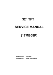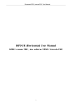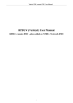
1
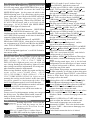
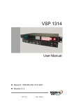
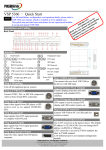
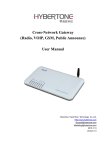
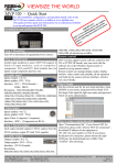
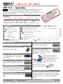
VIEW SIZE THE WORLD
–
For full installation,configuration,and operation details,refer to the
VSP1314 user manual,which is available at www.rgblink.com.
This guide provides quick start instructions for an experienced installer to set up
and operate the VSP1314.
r
fo
n
c al
k.
in anu on
l
b
ti
.rg er m ruc
e.
w
t
s
s
rc
ww te u n in the sou
to le
g
o
r
er mp llati ctin we
f
e
o
o
e
a
c
p
R e
st nn e
th d in co th
an fore ct to
be odu
pr
NOTE
Installation and cabling features
Rear Panel
Connections
1
USB Input Port
14 24
Power supply port of sending card
2 ~ 5 CVBS Input Port BNC
15 25 Send Card USB Control Port
6 7 VGA Input Port DB-15
16 26 DVI Input Port to Processor DVI Output。
Mini switches
8
17 ~ 19 DVI Input Port DVI-I
9
DVI Input Port DVI-I
RJ-45 Port
20
USB Control Port
10
21
DVI+VGA Output Port DVI-I
RS232
Control
Port
11
27 28 Power Port IEC-3
10/100M
Internet
Control
Port ,Connect to
12 13 22 23
LED Screen via cable
Step 1-Mounting
Turn off or disconnect all equipment power sources.
Step 2-CVBS Input Port BNC
Step7-Program(DVI1)Output Port
DVI Used to connect with DVI-based
display or LED control display.
Used to input composite signal ,including
Step8-Preview(DVI2+VGA) Output Port
(PAL,NTSC and SECAM)。
Used to connect with DVI-base
monitor so as to monitor the status of
input signal, or connect to VGA-base
monitor via a VGA cable.
DVI to DVI/VGA splitter
cable:One end is DVI-I or
DVI-D male, the other end is
DVI-I or DVI-D female
together with VGA male.
Step 3-VGA Input Port DB15
VGA Input used to connect signal from
VGA and DVD Player ,Compatible
with YPBPR.
Step 4-DVI1/2 Input Port DVI-I
DVI1/2 Input port support signal source
of HDMI from HD player or DVI from
PC.
Step5-DVI3 Input Port
DVI3 Input port support signal source of
PC;User can receive DVI signal via DVI
cable for background image or split image.
Step6-USB Input Port
USB Used to connect with USB or mobile
HDD.
DVI to VGA Adapter,it
has DVI-I male at one end
and VGA male at the other
end.
Step9-LAN(Ethernet)Port
Use twist CAT5 cable to connect to LAN port .Default
IP address: 192.168.0.100. Operator can also change
the IP address by RS 232 or USB.Twist CAT5 should
be one end in T568A, and another end in T568B
standard.
Address:Rm.S603-604,Weiye Building ,Torch Hi-Tech Industrial Development Zone,Xiamen,
Tel: 00865925771197
Fax:00865925771202
Email: [email protected]
http://www.rgblink.cn
VSP 1314 Quick Start
Version1.0
Page 1 of 3
Pins
Insert Twisted
Pair Wires RJ45 Connector
Crossover Cable
Pin
T568A Wire color
T568B Wire color
1
2
3
4
5
6
7
8
White-green
Green
White-orange
Blue
White-blue
White-orange
White-brown
Brown
White-orange
Orange
White-green
Blue
White-blue
Green
White-brown
Brown
T568A
CAT5 is
crosswire
standardized
with T568A
for one end
and T568B
for the other.
T568B
Step10-USB Port
USB cable Used to connect the VSP 1314 and
computer.
Step11-Serial Port
VSP 1314 support 9 kinds of output resolutions
as following:
1024×768×60Hz,1280×768×60Hz,1280×720×60Hz,
1280×1024×60Hz,1366×768×60Hz,1400×1050×60Hz,
1440×900×60Hz ,1680×1050×60Hz, 1920×1080×60Hz
Output resolution should be the same or bigger than
display system resolution.
NOTE Function button backlight instructions: the
green light means the upper function, the red light means
the lower function, no light means the function is at the
ready state. Such as press Menu/Effect ,
firstly the green light on and it is the Menu Functional
state, press again and go into Effect functional state with
red light on, press again, light out. And return to the
homepage.
NOTE
Use RS232-to-RJ11 cable to connect a control system
or computer to the back panel RJ11port and the other
end on RS232 port . Below is the definition for RS232- Step 2
Input switch
to-RJ11 cable.
VSP 1314 supports 4 composite inputs, 2个USB inputs, 2
Function
Function
RS-422
Pin RS-232
DVI inputs (compatible HDMI1.3), 2 VGA
Transmit(-)
2
TX
Transmit
TXinputs(compatible YPBPR), 1 background input (DVI
Receive(-)
3
RX
Receive
RXSignal
5
GND
Signal Ground
GND
1.0) , input signal via the corresponding interface. VSP
Ground
Receive(+)
7
--Not
Used
RX+
1314 supports 3 layer display. Layer 1 includes: The signal
Insert Twisted Pair
Transmit(+)
--Not Used
TX+
Wires RS232/RS422 8
source of CV1, CV2, USB1, DVI1, VGA1. Layer 2
Connector
includes: The signal source of CV3,CV4,USB2,DVI2,
RJ-11
Function
Pin
VGA2. Layer 3 is the background input, User can select
1
--Not Used
the background signal as DVI3 or the BLACK
2
RX
Receive
background.
3
TX
Transmit
Signal source key light instructions::
Insert Twisted
4
GND
Signal Ground
NOTE
Pair Wires
VSP 1314 Use the traffic light passing control
RJ11 connector
principle, The green light means in showing: Program
Step 12-Power Port
shows the image which green light refers; The yellow
VSP 1314 use signal power plug and pull for power
up, connect IEC port power line and VSP 1314 power light means to be broadcast; Preview shows the image
which the yellow light refers. The red light means
to start, and it support AC power from 85 to
ready for play, which means that the Preview signal can
265V ,which means world wide compatible.
be chose; No light means the user cannot work on the
Step 13-Power on
After power , LCD module on the front panel will show programming.
Default layer 1 is the Program output signal source of
RGBlink and its LOGO, as well as the following
DVI1 ,now the DVI backlight turns green, if signal
information: AVDSP series VSP 1314, cascadable 3
layers seamless switcher and mosaic scaler. Then come keys of the same layer are light off, they cannot be
selected; If users need to change the input signal of
into work menu homepage, and auto refresh LCD
Program, choose signal keys of any other layers. DVI2,
module menu display statue every two minutes and
the default signal of layer 2, lights on yellow , it means
display default input signals information and format,
Preview outputs DVI2. Other signal keys light on red ,
output format. User can operate with VSP1314 with
local front panel and remote control with the software user selects the signal key as needed, keys will light on
run on the PC,remote control by RS232,USB or TCP/IP. yellow as selected, tap TAKE button to change the
selected signal to Program output.
Local Control-Front Panel Operation
Step 1-Set Output Resolution
Press Menu/Effect , Rotate the knob to select Output
Format ,Press knob to select Output Resolution.
Setting, Select the Output resolution via rotating the
knob, rotate the knob again, Press Menu/Effect to the
homepage.
NOTE Press TAKE button to change signal between
Program and Preview. About the Menu( Menu/Effect
lights off) tap Menu/Effect, the key lights on green,
tap again to enter Effect page, then the key lights on
red, rotate the knob to select the needed effects of the
model, There are four kinds of effects for user to
select: Wipe Hard, Wipe Soft, FADE, CUT。
Address:Rm.S603-604,Weiye Building ,Torch Hi-Tech Industrial Development Zone,Xiamen,
Tel: 00865925771197
Fax: 00865925771202
Email: [email protected]
http: //www.rgblink.cn
VSP 1314 Quick Start
Version1.0
Page 2 of 3
Step 3
SCALE Setting
Press SCALE/CROP button, key lights on green to the
SCALE setup menu, when HSIZE/HPOS turns green,
user can adjust HSIZE via rotate the knob, Tap
HSIZE/HPOS again,the key turns red which is the
HPOS adjusting state. Tap a third time, the key turns
green again and it goes back to the HSIZE adjusting
state. And the same adjusting way goes for
VSIZE/VPOS adjusting. When setup finished, tap
SCALE/CROP button and it goes back to the
h o m e p a g e , S C A L E / C R O P a n d HSIZE / HPOS ,
VSIZE/VPOS light off, function off.
NOTE 1.At SCALE\CROP function ,HSIZE/HPOS
function and VSIZE/VPOS function can’t be
implemented at the same time .Adjust HSIZE/HPOS or
else VSIZE/VPOS separately at one time for their keys
cannot be lighted on together.
2.When SCALE/CROP functions off, tap HSIZE/
HPOS, then VSIZE/VPOS,when these two keys light
on, set parameters of SCALE and CROP to the default
value: FULLSCREEN functions on. Lights off when
parameters are set.
3. DVI3 background signal can’t set SCALE when in
non-mosaic mode .
Step 4-Save and Load
Press SAVE/LOAD: The key lights on green and enter
S A V E s t a t e , a l l o f CV1 / 1, CV2 / 2, USB1 / 3 ,
DVI1 / 4,VGA1 / 5 , CV3 / 6, CV4 / 7, USB2 / 8,
DVI2/9,VGA2/10 light on green, user can select and
save. Saving finished, the selected key lights off, while
other savings can still be implemented. At saving state,
other functions cannot be implemented.
When savings finished ,tap this key again and the key
turns red to enter LOAD state, all of
CV1 / 1,CV2 / 2,USB1 / 3 , DVI1 / 4,VGA1 / 5 , CV3 / 6,
CV4 / 7, USB2 / 8,DVI2 / 9,VGA 2 / 10 l i g h t o n r e d
meaning the savings can be loaded. At the time other
f u n c t i o n s c a n n o t b e i mp l e m e n t e d e i t h e r . T a p
SAVE/LOAD button again to exit LOAD function.
NOTE SAVE1 is the default user mode,it will work
on SAVE1 mode when power on
VSP1314 .After factory reset ,all the user modes are
initialized.
Factory reset: For fault parameter setting, user can go to
the factory reset. Tap Menu/Effect button, rotate the
knob, select the factory reset function, tap again to
confirm, factory reset is done.
Step 5-Color operation panel
1
Starting-up LOGO:Power on the
device and the image on left is
shown on LCD screen for the
initializing process.
PIP1 is 1/2 mode: Layer 1 is above Layer 2.
Press PIP1/PIP2, and the key lights on green.
PIP2 is 2/1 mode: Layer 2 is above Layer 1.
Press PIP2/PIP1, then the key turns red.
V1 The play type of USB1 is video, it is the default
mode . User can select Movie via MENU
USB Setting
USB1
USB1 Play Type, and
the sign will be showed on homepage.
V2 The play type of USB2 is video, it is the default
mode . User can select Movie via MENU
USB Setting
USB2
USB2 Play Type, and
the sign will be showed on homepage.
P1 The play type of USB1 is image, it is the default
mode . User can select Photo via MENU USB
Setting
USB1
USB1 Play Type, and the
sign will be showed on homepage.
P2 The play type of USB2 is image, it is the default
mode . User can select Photo via MENU
USB Setting
USB2 USB2 Play Type, and
the sign will be showed on homepage.
B Background overlying .Select DVI3 via
MENU
Output
Background,and the
sign will be showed on homepage.
Background
input setting.Select DVI3 via MENU
B
Input
Input Matrix
Channel3, and the
sign will be showed on homepage.
3 VSP 1314's maximum display and default
working mode is 3 display layers.
Test Parrern,Then select
TP Test Pattern. MENU
scroll mode, return to the homepage can see The
mark.
Brack background input, this is the default
configuration. Set the third layer of input matrix
or output background as Black, return to the
homepage can see the mark.
Draw curtain.This position was automatic/manual
W
ALPHA originally, It will show in here when open
the mode. Operation: Enter EFFECT, select Effects
Mode as Wipe Hard, Wipe Soft mode, return to
homepage can see the mark.
Splicing.Select ON via MENU Split
Split
Switch,Return to homepage can see the mark.
Screen Windows Mode,Select Screen via MENU
OUTPUT
Screen
Windows Mode,
return to homepage can see the mark.
F Full Screen ,this is default mode or can select
FULL via MENU OUTPUT
Scree
Windows Mode,return to homepage can see the
mark.
M Manual ALPHA.Press TAKE and rotate
knob to adjust the indicator to another end,
Then return to homepage can see the mark.
A Automatic ALPHA,this is the default mode.
Or press TAKE ,then return to homepage can
see the mark.
Coded lock.It means the device is locked.
2
Address:Rm.S603-604,Weiye Building ,Torch Hi-Tech Industrial Development Zone,Xiamen,
Tel: 00865925771197
Fax: 00865925771202
Email: [email protected]
http: //www.rgblink.cn
VSP 1314 Quick Start
Version1.0
Page 3 of 3