1
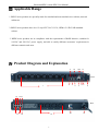
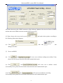
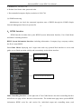
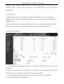
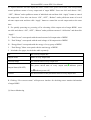
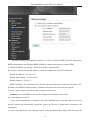
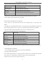
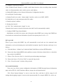
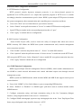
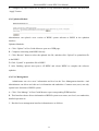
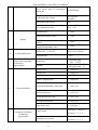
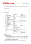
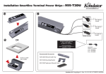
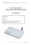
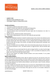
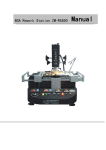
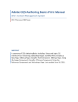
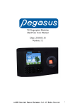
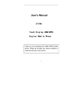
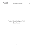
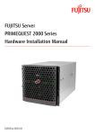
Horizontal PDU, remote PDU User Manual
RPDUH (Horizontal) User Manual
RPDU: remote PDU , also called as NPDU: Network PDU
1
Horizontal PDU, remote PDU User Manual
Contents
Ⅰ. RPDU Introduction ......................................................................................................................... 3
Ⅱ. Function Description ....................................................................................................................... 3
Ⅲ. Applicable Range ............................................................................................................................ 5
Ⅳ. Product Diagram and Explanation .................................................................................................. 5
Ⅴ. Installation Method ......................................................................................................................... 6
Ⅵ. RPDU Hardware Introduction ........................................................................................................ 7
1. Powering on & Self-detection ........................................................................................................ 7
2. Monitoring Current Load, Temperature & Humidity ........................................................................ 7
3. Monitoring Waterlogging & Smoke State ........................................................................................ 7
4. Monitoring Operation Fault of outlets ............................................................................................. 7
5. Monitoring and Alarming when Exceeds Preset Alarm Threshold Value………………………………..7
6. Monitoring Self-detected Information ............................................................................................. 8
7. Stopping Present Alarming State..................................................................................................... 8
8. Configuring Master / Subordinative RPDU ..................................................................................... 8
9. Daisy-chain Connection Method..................................................................................................... 8
10. Radialized Connection Method ..................................................................................................... 9
11. Software Updation ......................................................................................................................10
Ⅶ. RPDU Software Introduction .........................................................................................................12
1. Software Overview ……………………..………………………………………………………..…...…12
2. Software Function Description……………………………………………………………………...…...12
3. Accessing Method……………………………………………………… ………………………….…...13
4. HTML Interface…………………………………………………….……………………….…..……....14
5. Daisy-chain Method & Configuration………………………………………………………….………25
6. FAQ and Solutions………………………………..………………………………………… …….… ..26
Ⅷ. Operation Steps ……………………..……… …………………………………… …………………….27
Ⅸ. Performance &Technical Parameter Table…………………………………………..………..….........27
Ⅹ. Quality Guarantee Policy ………………………………………………………………….………...
2
29
Horizontal PDU, remote PDU User Manual
Ⅰ. RPDU Introduction
RPDU can monitor, control and manage the power supply of electrical and electronic
equipments in standard and non standard cabinets all over the world through LAN or WAN.
RPDU can be accessed by different connection methods to satisfy different requirements in
different environment: can be accessed through RJ45 interface in the LAN and WAN; can be
accessed through standard network management station.
Ⅱ. Function Description
1. Monitoring Function: monitor the operation of present RPDU, total current load, individual
current load(not available for A series), power on/off state of individual output unit(not available for
A series), temperature/humidity state, Smoke state, waterlogging state, door open/close state through
the display interface and knob on RPDU. And also can monitor, control and manage through LAN or
WAN.
2. Controlling Function (not available for A series): control the Power on/off of output units;
Schedule the interval-time of sequential power on/off. Setting Power On /Off of output units.
3. Original State Keeping Function (not available for A series): Keep the original state of
each output unit when RPDU is reset.
4. Alarm Threshold Value User-Defined Function: Preset the min. & max total current
load value, current load of individual output unit (not available for A series), and
temperature/humidity value.
5. System Default Alarm Function: Alarm when total current load is over preset value or
individual output unit current load is over preset value (not available for A series) or individual
3
Horizontal PDU, remote PDU User Manual
output unit fails to work normally (not available for A series), or Smoke appears, or waterlogging
happens, or when cabinet door opens.
6. Multi-alarm Functions: Operation Indicator flashes; Alarm Buzzer rings on RPDU control
panel. The current overload value is displayed and flashes on web browser Managing Interface
and PC buzzer alarms. Automatically send e-mail to related administrator. SNMP sends alarm
information. Automatic wireless access sends to administrator.
7. Energy Measurement: Automatically record total current consumption per unit time.
8. Daisy-chain Functions: By using the methods of series connection or radicalized
connection, up to 10 pieces of RPDU (including the Master RPDU) can be connected together to
be monitored and managed in front of one control interface.
9. Event Log Record: Recording and saving alarm information of present RPDU for Tracing
and Collecting. (Attention: Log record can be read only by sequence, and the information is:
load current value exceeded, Temperature/Humidity value exceeded, Smoke appears,
waterlogging happens, or when cabinet door opens, output units operate, individual output unit
fails to work normally, sensors outputted or inputted)
10. User Management: user’s authority can be configured.
11. Access method: can be accessed through web IE. Accessing and controlling through Standard
Network Management Protocal, that is, SNMP(V1/V2.Accessing and controlling through the
console of the commanding form, that is Telnet, SSH,
12. System Support: Supporting multi-user operation and software updation.
4
Horizontal PDU, remote PDU User Manual
Ⅲ. Applicable Range
1. RPDU series products are specially made for standard and non-standard server cabinet, network
cabinet etc.
2. RPDU series products have 8 or 12 ways IEC320 C13/C19, NEMA 5-15R/5-20R standard
sockets.
3. RPDU series products are in compliance with the requirements of RoHS directive, suitable for
110VAC and 220 VAC power supply, and able to satisfy different customers’ requirements in
different countries and areas.
Ⅳ. Product Diagram and Explanation
9
10
11 12 13
Front
2
1
3
4
5
6 7
8
14 15 16
Rear
17
19
18
5
20
21
Horizontal PDU, remote PDU User Manual
1/19: Output Unit Address: can carry up to 8 ways 0f output unit (IEC320 C13/C19 or NEMA
5-15R/5-20R)
2. Port1: Port of uploading file for RPDU software Updation.
3. LINK: used when daisy-chain needed, LINK port connect to SER port of next RPDU
4. SER: Port used when daisy-chain needed, SER port connect to LINK port of former RPDU
5. NET: Port used for connecting RPDU to RJ45 port of PC, HUB, router or switcher, and thus
remotely control is available.
6. NO.2 Button: switching over selected output parameters.
7. RESET Button: Used when configuring Master/Subordinative RPDU and reset.
8. Fixed install bracket
9/10. Display Board: display output address and corresponding current value
11. RUN: Operation Indicator.
12. M/S: Master/Subordinative RPDU Indicator (Master RPDU is indicated with lighted M/S
Indicator).
13. No.1: selecting output parameters.
14. Door1, Door2: Door Sensor Port
15. Water: Waterlogging Sensor Port
16. Smoke: Smoke Sensor Port
17. T/H1, T/H2, T/H3: Temperature/Humidity Sensor Port
18.Port2:Un-appointed RS485 port
20. Overload Protector.
21. Cable mounting hole
Ⅴ. Installation Method
Horizontal Fixed Installation
6
Horizontal PDU, remote PDU User Manual
Ⅵ. RPDU Hardware Introduction
1. Powering on & Self-detection
Once the circuit is powered on, RPDU will firstly self-detected: Alarm Buzzer will make a sound,
then LED Operation Indicator on RPDU function modular panel will light, Display Board will
sequentially displays 8.8.8. 8.8.8. ( indicating that LED in normal operation state), Software
Version(e.g.: U0.0
1.01) Baud Rate (e.g.: 9 600), Serial Number(e.g.: ABC DEF), Product Model
310 1-d, Total Socket Quantity(e.g.:OU7
08), finally displays Output Unit No. and its
corresponding current load value(e.g.: A1 0.0), and at this point LED Operation Indicator will flash.
And Master RPDU is indicated with M/S Indicator lighted on, and Subordinative RPDU with M/S
Indicator off.
2. Monitoring Current Load, Voltage, Temperature & Humidity
Monitoring corresponding current load value output unit by turning button (No.1: select, No.2:
reset).
3. Monitoring Waterlogging & Smoke State
(1) When waterlogging state is detected, RPDU Display Board displays F2, and Alarm Buzzer rings
at the same time.
(2) When Smoke state is detected, RPDU Display Board displays F1,and Alarm Buzzer rings at the
same time.
4. Monitoring Operation Fault of output units
When one output unit fails to work normally (for example: A1), RPDU Display Board will display
corresponding fault (for example: A1 Err), and Alarm Buzzer will ring at the same time.
7
Horizontal PDU, remote PDU User Manual
5. Monitoring and Alarming When Exceeds Preset Alarm Threshold Value
(1) Alarm when the actual value of individual output unit current load, total current load, and
temperature & humidity are lower than preset limited min. value. For example, when any of the
above situation happens at output unit A1, RPDU Display Board will alarm by displaying A.1 and
Alarm Buzzer will ring to alter related administrator.
(2) Alarm when the actual value of individual output unit current load, total current load,
temperature & humidity are higher than preset limited max value. For example, when any of the
above situation happens at output unit A1, RPDU Display Board will alarm by displaying A.1. . and
Alarm Buzzer will ring to alter related administrator.
6. Monitoring Self-detected Information
Turn No.1 Button to display --- --- , then press RESET Button, and RPDU Display Board will
sequentially displays RPDU Self-detected Information for one minute.
7. Stopping Present Alarming State
It needs to press RESET button to stop Alarm Function for one minute (When RPDU is alarming,
No.1 Button is not workable. Other information can be checked but it still alarms after one minute
unless operation fault is cleared.)
8. Configuring Master / Subordinative RPDU
Press RESET button for 10-13 seconds, M/S Indicator will light to indicate master RPDU. Press
RESET button for 5-8 seconds, M/S Indicator will off, and it indicate Subordinative RPDU. The
calculation of time can see the RUN indicator (T= 2 seconds)
9. Daisy-chain Connection Method
Please refer the following Diagram and Operation Steps.
8
Horizontal PDU, remote PDU User Manual
(1) Each RPDU has exclusive Serial No. different from others, which have been appointed before
leaving factory and can not be changed.
(2) Once Master RPDU is appointed, and the others will automatically become Subordinative RPDU.
Up to 10 pieces of RPDU can be connected together.
(3) Connect one end of attached network line to LINK port of Master RPDU and the other end
to SER Port of first Subordinative RPDU, and then connect one end of network line to LINK
port of first Subordinative RPDU and the other end to the SER Port of second Subordinative
RPDU, and goes on until all the RPDU (10 pieces at most) are connected together.
(4) Connect one end of attached network line to net port of PC, and the other end to NET Port of
Master RPDU,accessing through IE.(Details please refers to Software Introduction)
10. Radialized Connection Method
Please refer the following Diagram and Operation Steps.
(1) Appoint one Master RPDU and the others automatically become Subordinative RPDU.Up
to 10 pieces of RPDU can be connected together.
(2) Connect one end of attached network line to net port of PC, and the other end to NET Port of
9
Horizontal PDU, remote PDU User Manual
Master RPDU.
(3) Connect one end of attached network line to LINK port of Master RPDU, the other end to
one IN/OUT port of the HUB.
(4) Connect one end of second network line to another IN/OUT port of the HUB, the other end to
the SER port of first Subordinative RPDU, then connect one end of third network line to another
IN/OUT port of the HUB, the other end to the SER port of second Subordinative RPDU, and 10
pieces RPDU at most can be connected together.
(5) Access to software control interface through IE web browser (details please refers to Software
Introduction)
11. Software Updation Method:
(1) When Software Updation File
is available, and please save it in PC.
, and then double click file “setup.exe” to
(2) Open Software Updation File
install the software.
(3) Run the installed software, the following Interface will come out:
10
Horizontal PDU, remote PDU User Manual
(4) Please insert one end of RJ45 connector of the Software Updation Line into the Port1 of RPDU,
and the other end of DB9 connector into the RS232 port of PC.
(5) Please choose the correct series port in
, and make other options according to
the following illustration diagrams:
(6) Click
in
, and add
into
dialogue interface.
(7) Power on RPDU.
(8) Click
, and
will come out to indicate reading successfully. If not,
please check relevant connection line and communication port.
(9) Click
, and
will come out to indicate erased
successfully. If not, please check relevant connection line and communication port.
(10) Click
, and
will come out to indicate executing
successfully. If not, please check relevant connection line and communication port.
11
Horizontal PDU, remote PDU User Manual
(11) Power off RPDU.
(12) Then power on RPDU, Display Board will show new version number to indicate successful
software updation and then it can work normally.
Ⅶ. RPDU Software Introduction
1. Software Overview
The software of RPDU is embedded applications software. On the base of the monitoring and
controlling technology of SNMP, and integrating a variety of high-tech as sensor network node
technologies. It a remote intelligent controlling and managing system that is connected RPDU
(Network Power Distribution Unit) network devices in the cabinet to enable monitoring and
controlling through network. RPDU administor can monitor, control and manage many pieces of
electrical and electronic equipments in standard or non-standard cabinets all over the world through
LAN and WAN. And supporting hardware sensor monitoring: Temperature/Humidity Sensor, Door
Open/Close Sensor, Waterogging Sensor and Smoke Sensor. It provides very easy and friendly Web
operation interface, a system supporting mutiple-user, and it is compatible with various kinds of
network connection.
2. Software Function Description
(1) Basic Function Description
A. Support IE (Internet Explorer) browser access method, providing friendly operation interface,
supporting multi-user.
B. Support Network Configuration: the parameters of IP, subnet mask, gateway and DNS can
modified accordingly.
C. Support remote monitoring, controlling and managing through network
D. Support 10 pieces of RPDU daisy-chained or radialized connected together to be centrally
configured and managed in front of one operation interface.
12
Horizontal PDU, remote PDU User Manual
E. Support monitoring individual output unit current load and total current load.
F. Support controlling the power on/off state on individual output unit level and that on output unit
group level, and indicating the state with LED.
G. Support reset function on individual output unit level and that on output unit group level.
H. Support preseting the current load alarm threshold value of on individual output unit level, on
output unit group level and on the whole RPDU system level.
I. Support detecting total voltage, energy group and total energy.
J. Support controlling the power on/off state of individual output unit.
K. Support reading log records and deleting function.
L. Support keeping the original state of output units when reset.
M. Support preseting the temperature/humidity alarm threshold value.
N. Support monitoring the state of temperature/humidity, Smoke, water and door open sensors in the
RPDU installed cabinet
O. Support sound, e-mail and SNMP alarm function
(2) Advanced Function Description:
A. Support checking RPDU version No., hardware address and other system information.
B. Support HTTP/SSL configuration information.
C. Support Telnet/SSH configuration information.
D. Support SNMP network management function.
E. Support updation on software system level.
F. Support updation on hardware system level.
G. Support Adding/deleting users, configuring users’ authorities, modifying users’ information and
other functions.
H. Support resetting RPDU function.
I. Support system exiting function.
3. Accessing Methods
(1) IE (Internet Explorer) Browser Access Method.
A. Users connect computer with the network through LAN and WAN, then open IE, and input the IP
address of RPDU to access, then can monitor, control and manage the power supply of
equipments connected to the RPDU.
13
Horizontal PDU, remote PDU User Manual
a. Default IP is: 192.168.1.163.
b. Default User Name: adm; password: adm.
c. Recommended computer display resolution is 1024*768.
(2) SNMP monitoring
Administrator can check the unnormal operation state of RPDU through the SNMP (Simple
Network Management Protocol) system flat.
4.HTML Interface
HTML Interface includes three parts: RPDU System Information Interface, User Guide Menu
and Main Controlling Interface.
RPDU System Information Interface: including information of company logo, company website,
the IP of current RPDU.
User Guide Menu: displaying user’s login name and easy operated Web interface to access and
guide user to finish operation quickly and conveniently. As the below interface:
Current User Name
Basic Function Interface
Advanced Function Interface
Main Controlling Interface: on the right side of User Guide Menu is the main controlling interface
and all the web page will be showed on this interface. The default main page shows present RPDU
information: RPDU series No. and version No., individual output unit controlling menu, total
14
Horizontal PDU, remote PDU User Manual
controlling menu, individual output unit name, individual current load, total current load of
individual RPDU, sensors monitor information of individual RPDU and other parameter
configurations.
(1) Login Method
A. Run IE (Internet Explorer) and input the IP address of the RPDU, then input the login name
and password on Login Dialog Interface, and finally click “yes” button to enter the HTML Interface
of RPDU system.
B. Users have three chances to login, further wrong login name or password input, the system will
automatically login out the Login Dialog Interface; users have to repeat operation step A.
(2) OUTLETS Controlling
A. The above RPDU Controlling Interface can be accessed by clicking “Device Control” on User
Guide Menu.
B. Under the pull-down menu of “Select Device” lists the names of daisy-chained RPDU, users can
click and choose to open the power controlling interface of target RPDU.
C. Opened Interface will display the name, version No. and series No. of present RPDU.
For example: RPDUH B Series (RPDUH B).
15
Horizontal PDU, remote PDU User Manual
D. Opened Interface will also display the name, current value, power on/off state, and corresponding
control pull-down menu of every output unit of target RPDU. Users can click and choose “ON”,
“OFF”, “Reboot” under pull-down menu of individual unit and then click “Apply” button to control
the output unit. Users also can choose “ON”, “OFF”, “Reboot” under pull-down menu of several
relevant output units and then click “Apply” button to control the several output units at the same
time.
E. For quickly powering on, powering off or rebooting all the output unit of target RPDU, users
can click and choose “ON”, “OFF”, “Reboot” under pull-down menu of “All Outlets” and then click
“Apply”.
F. “Total Current” corresponds with the total current of all output units of RPDU.
G. “Total Voltage” corresponds with the total voltage of all output units of RPDU.
H. “Energy Meter” corresponds with the energy of every group of RPDU.
I. “Total Energy” Meter correspond with the total energy of RPDU.
J. It includes five pages, As the below table separately:
No.
No. of every output unit
Output Name
Name of every output unit
Current(Amps)
The current load of every output unit
●indicates
The power on/off state of every output unit(
Output Status(ON/OFF)
power
●indicates power off)
on,
Control
The on/off button of the pull-down menu of every output unit
K. Clicking “View sensors status” will open new interface for checking sensor monitor information
of target RPDU.
(3) Sensor Monitoring
16
Horizontal PDU, remote PDU User Manual
The above Sensor Monitoring Interface monitors the state of temperature/ humidity, Smoke,
waterlogging and door open/close of the cabinets in which installed RPDU. When the
temperature/humidity values exceed alarm threshold value, temperature/humidity value will become
red and flash to alarm.
A. Sensor information includes: Sensor name, temperature/humidity value, state and relative data of
Smoke, water, door open/close.
B. For sensor monitoring information of different RPDU, users can select the pull-down menu of
daisy-chained device, and then choose every daisy-chained RPDU through the interface.
C. When there is no sensor connected or not connected correctly, sensor state will be “Not found”
D. When the temperature/humidity values exceed alarm threshold value, temperature/humidity value
will become red and flash to alarm.
E. When Smoke state appears, Smoke sensor value will become red “YES” and flash to alarm.
F. When cabinet door is opened, related door sensor value will become red “OPEN” and flash to
alarm
G. When waterlogging happens, related waterlogging sensor value will become red “YES” and flash
to alarm.
H. Clicking “Refresh” button at any time to refresh the state and get updated information.
(4) RPDU Device Configuration
17
Horizontal PDU, remote PDU User Manual
The above RPDU Device Configuration Interface is mainly used to configure daisy-chained
RPDU's
device, add or modify the daisy-chained device's name, address, interval-time for
sequential power on, individual output unit's name and other information. Specific operations are as
follows:
A. The corresponding pull-down menu of "Select Device"will display the name of the present
selected RPDU.
B. Input the daisy-chained RPDU No. in the dialogue interfaces “RPDU Address No.” The No. is
factory settings and exclusive value. It can’t be the same as other RPDUs’ No. when daisy-chained,
otherwise, errors will be found.
C. “RPDU name” dialogue interface is used to name daisy-chained RPDUs. For convenient
management, exclusive name for individual RPDU is recommended.
D. “1-24” dialogue interfaces are used to name individual output unit.
E. “Sequence Interval” dialogue interface, input interval-time value 0~255, which is used to check
and modify the sequential power of the daisy-chained RPDU
F. Click “Apply” button to save configured information
(5) Network Information Configuration
18
Horizontal PDU, remote PDU User Manual
The above network configuration interface is used to configure RPDU network information.
RPDU administrator can configure RPDU IP address, subnet mask, gateway address, DNS.
A. Default IP address by clicking “Obtain an IP address automatically”.
B. Clicking “Use the following IP address” button to configure the network information:
Default IP Address:192.168.1.163
Default Subnet Mask:255.255.255.0
Default Gateway: 192.168.1.1
RPDU IP address, PC connected with LAW and other network devices can not be the same as PC
IP address, but RPDU IP address and PC IP address must be in the same network segment.
C. Click “Apply” button, then all the above settings will be saved.
Attention: Power off RPDU to restart, the configured information will be valid.
(6) Controlling Power on/off
Power on/off controlling is according to the needs, administrator sets the time that power on/off,
and the system will automatically control the power on/off state of output units according to the
setting time.
A. Users click and choose the “Timing Control” under the Main Guide Menu, and then open the
19
Horizontal PDU, remote PDU User Manual
corresponding HTML interface.
B. In the interface, users choose the daisy-chained RPDU under pull-down menu of the
daisy-chained device to enable to control power on/off sequentially of the RPDU.
C. “Local time” displays the users’ local time correspondly, “RPDU Clock” corresponds with the
RPDU’s date and time. When the date and time is not the same as users’ local time, users can click
the “setting” button to check the RPDU’s clock.
D. The page is divided into 4 lines:
No.
Corresponding with the No. of every output unit of RPDU
Output Name
Corresponding with the name of every output unit
Corresponding with dialogue interface of the power on
ON Timing(yy/mm/dd)
time-interval of every output unit
Corresponding with dialogue interface of the power off
OFF Timing(yy/mm/dd)
time-interval of every output unit
E. Users set the power on/off time-interval of every output unit of RPDU through the tips about
time form under the page. And then click the “Apply” button, information of “Set success” comes
out and users set it successfully.
F. Choose “Repeat”, setting successfully, and then the RPDU will power on/off according to the
settings on schedule.
(7) Alarming Function and Configuration
Exceeding value alarms includes total/individual current load value, Max. &Min value of
temperature/humidity. When the current value of individual output unit and temperature/humidity
value exceed preset alarm threshold value, alarm buzzer on RPDU panel will rings to alarm and at
the same time relevant current overload value and temperature/humidity sensors value will become
red and flash to alarm.
Alarm Manners: sound alarm and e-mail alarm, SNMP Traps
A. Current Load Alarming Function Configuration
a. Click “Alarm” on User Guide Menu and then click “Threshold Value” to open relative HTML
interface
b. Open the corresponding HTML interface. Choose the daisy-chained RPDU under pull-down menu
of the daisy-chained device to enable to set current load alarm threshold value of RPDU.
c. Input Max. &Min. current load value (it can’t exceed the rating value)
20
Horizontal PDU, remote PDU User Manual
d. Interface detailed information is included in the below table
NO.
Individual output unit number
Output unit Name
Individual output unit name
Current(Amps)
Individual output unit current load
Overload
Individual output unit max current load
Low limit
Individual output unit minimal current load value
High limit
Individual output unit maximal current load value
e. “Total Current” corresponds with the total current load alarm threshold value of RPDU
f. Click “Apply” button to submit and set successfully.
B. Environment Alarming Function Configuration
a. Click “ Alarm” on User Guide Menu and then click “Threshold Value” to open relative web
interface
b. Opening the corresponding HTML interface. Choosing the daisy-chained RPDU under pull-down
menu of the daisy-chained device to enable to set current load alarm threshold value of RPDU.
c. Input Max. &Min. temperature/humidity value (it can’t exceed the rating value)
d. This interface detailed information is as following table:
Name
sensor name
Current Temperature
current temperature sensor value
Low limit
minimal temperature sensor threshold
High limit
maximal temperature sensor threshold
Current Humidity
current humidity sensor value
Low limit
minimal humidity sensor threshold
High limit
maximal humidity sensor threshold
e. Click “Apply” button to submit and save the configured temperature/humidity sensor information
C. Alarming Method Configuration
Three alarming methods: sound alarm and e-mail alarm, SNMP Traps
a. Configure Sound Alarm Method
Click “Enabled Sound Prompt” to enable sound alarm function, when exceeding alarm threshold
value, alarm on PC of administrator of RPDU will ring to alarm related administrator.
(Attention: the web browser must support audio player)
21
Horizontal PDU, remote PDU User Manual
b. Configure E-Mail Alarm Method
Click “Enabled E-mail Prompt” to enable e-mail alarm function, when exceeding alarm threshold
value, it will automatically send e-mail to preset e-mail address
a). Setting DNS address on the Network Information Configuration interface
b). Activing the E-mail settings
c). Setting E-mail sever on the “Alarm setting” interface, such as sever POP3, SMTP.
d). Setting the user’s name and password of the sender
e). Setting recipient’s address
f). Setting time-interval
g). Click “Test”, and then press “Apply” to save.
(Attention: there must be network connection when the E-mail is automatically sended)
c. Configure SNMP Traps Alarm Method
Administator can check the newest state information when RPDU goes wrong. And SNMP can
record and save unnormal state information. Specific description please see No. (11)
(8) Log record
When it goes wrong with RPDU, log will automatically record and save the unnormal state
information, and record alarming time and detailed description. Specific functions and steps is are
follows:
A. Click and choose “Alarms Logs” under the Main Guide Menu, and open WEB interface.
B. Choose the daisy-chained RPDU under pull-down menu of the daisy-chained device to check the
log records of each RPDU.
C. Choose “First, Previous, Next” to view the log records turning around pages.
D. Choose the form as “Txt, Excel, Web” to export the log records.
E. Click “Clear all records” to delete all log records.
(9) System Information
Users can view all the system configuration information of RPDU through System Information
page, such as FW No., MAC hardware address, storage size and operation time.
Click “Reset System Settings” to reset to come into force, and then it will be empty for all
settings when logging in again, so users need to input manually. For example: RPDU No., and so on.
22
Horizontal PDU, remote PDU User Manual
(10) HTTP/SSL Configuration Information
A. HTTP Function Configuration
HTTP protocol, namely hypertext transport protocols, is an object-oriented protocol in
application level. HTTP protocol is so simple that operation program of HTTP server is smaller
accordingly, therefore communication speed is faster. RPDU system adopts HTTP protocol to make
the system management, data communication and controlling more convenient and faster.
a.
Users click “Web” on User Guide Menu to open relative interface.
b. Select “Enable” on the pull-down menu of “Server” to enable HTTP function configuration.
c.
Input HTTP port number in the corresponding input interface of “port”.
d. Click “Apply” to submit and save configuration.
B. SSL Function Configuration
Secure Socket Layers (SSL), used to ensure the safety of transport data when users access
RPDU remotely. SSL Makes the RPDU data system communication safer, network management
more convenient and safer.
a.
Click “Enable” under the drop-down menu of “Server” to enable SSL function
b. Click “Optional” under the pull-down menu of “Secure Access” to enable the unsafe HTTP and
SSL encryption HTTP access. Select “Required” only to enable SSL encryption connection interview
c.
Click “Apply” button to submit and save configuration
(11) SNMP Function Configuration
RPDU support Simple Network management Protocol (SNMP), which enables administrator to
use SNMP to search network information and control individual output units through network
management system.
RPDU system has SNMP function which includes MIB I and MIB II and support remote power
control function.
A. Users click “SNMP” in User Guide Menu to open corresponding WEB interface.
B. Select “Enabled” or “Disabled” in “SNMP Agent” pull-down menu to confirm whether enable
SNMP function
C. Configure community string; and input community string in the Get Community dialogue
interface, string length should be in the area of 1-24 characters.
D. Configure SNMP calculagraph, input one trap calculagraph value in the Error Trap Repeat Time
frame, trap calculagraph value should be between 1-65535
23
Horizontal PDU, remote PDU User Manual
E. Configure trap object, input one IP address on Trap Destination dialogue interface and then click
“Apply” button.
(12) Updation Method
Administrator can upload a new version of RPDU system software to RPDU in the updation
interface.
Updation Methods:
A. Click “Update” in User Guide Menu to open new WEB page.
B. Computer connecting with RPDU directly.
C. Click “Browse” button to select the updated .bin file, and then click “Upload” to upload this file
to the RPDU.
D. Click “Upload” to upload the file to RPDU.
F. After finishing upload, must power off RPDU and reboot RPDU to complete the software
updation.
(13) User Management
Administrator can view users’ information and level on the User Management interface. And
Administrator can delete and edit user’s information and authorities. Common user (user) can only
operate basic functions of RPDU system.
A. Click “User Manage” in User Guide Menu to open corresponding WEB Interface.
B. This Interface shows all user information of RPDU system: user name, user level, user authorities,
detailed operation etc.
C. Details of user management interface information are as follows:
24
Horizontal PDU, remote PDU User Manual
User Name
User name
Level
include two level of use: “Administrator” is senior user and the others
are common user “User”
Control Rights
User authority editing, click “Edit” to enter user authority editing interface.
Action
click “Edit” to enter user information editing interface to edit user
password, user lever
click “Remove” button to delete target users
D. Click “New User” to enter new user creating interface.
E. Click “Edit” under “Level” to edit user’s name and password.
F. Click “Edit” under “Control Rights” to set user authorities.
G. Click “Remove” to delete the corresponding user.
(14) Reset System
Click “Restart” under the Main Guide Menu, and click “Restart” on the WEB interface, reset RPDU
system.
(15) Logout System
Click “Logout” under the Main Guide Menu, and click “Yes” on the WEB interface, logout RPDU
system.
5.RPDU Daisy-chain Method & Configuration
(1) Daisy-chain Method
25
Horizontal PDU, remote PDU User Manual
A. Firstly connect and configure one master RPDU and then subordinative RPDUs, confirm the
connection is correct.
When present RPDU is in subordinative state (indicated with off M/S
Master RPDU indicator), press RESET button for 12 seconds (until M/S indicator flashes
Configuration
about six times), and when M/S indicator is lighted, present RPDU master
RPDU is successfully configured.
When present RPDU is in master state (indicated with on M/S indicator),
Subordinative
press RESET button for 6 seconds (until M/S indicator flashes about three
RPDU
times), and when M/S indicator is off, master RPDU is successfully
Configuration
configured.
B. Input IP address of master RPDU IP address to open RPDU WEB system, and then enter Device
Configuration interface.
C. Input Ethernet Address of daisy-chain in RPDU “Address No.” dialogue interface and configure
the names of daisy-chained RPDU in “RPDU Name” dialogue interface.
D. Click “Apply” button to submit and save configurated information
E. Click “Device Control” on User Guide Menu to open RPDU Control Interface, then click to
choose target RPDU from “select device” pull-down menu, and if data information of opened target
RPDU can be read successfully, and this indicate the RPDU daisy-chain connection is correct.
(2) Daisy-chain Configuration
A. Confirm all the ethernet address of daisy-chained RPDUs be exclusive(different from each other;
B. Give exclusive name to every single daisy-chain RPDU to avoid confusion;
6.FAQ and Solutions
(1) Input RPDU IP and then press “enter” but can not see Login Dialogue Interface.
Solution: Firstly configure and confirm RPDU IP and the PC IP connected with RPDU are in the
same network segment, Ping NPM IP address to confirm network connection is in normal state.
(2) Input user name and password in Login Dialogue Interface but can not enter RPDU Web interface
Solution: Please confirm whether user name and password are correct and submit again
(3) Entering into RPDU Web interface but can not read RPDU state;
Solution: open “Device Configuration” to check whether RPDU address on “Address No.”
dialogue interface is correct, refresh to read after confirming this address is the same as that of
related RPDU address, If not the same, please input correct RPDU address on “Address No.”
26
Horizontal PDU, remote PDU User Manual
dialogue interface, and then click “Apply” to save and read RPDU state again.
Ⅷ. Operation Steps
1.Horizontally fix RPDU.
2.Connect temperature/humidity, waterlogging, Smoke and door sensors correctly
3.Choose connection method according to specific requirements (details please refer to chapter Six)
4.Connect RPDU plug to AC power source, then connect and configure master and subordinative
RPDU, and finally run IE browser to configure relevant parameter correctly.
Ⅸ. Performance & Technical Parameter Table
Performance Parameter
No.
1
2
Technical Parameter
rated input voltage
125/250VAC
50/60HZ
input plug
IEC60309
industrial
standard plug/IP44
cable dimension
3×2.5mm²、3×6.0mm²
cable length
2M
max. input current
16A、32A
socket standard
IEC320 C13
output unit quantity
8 ways
(horizontal installation)
Input
Output
27
Horizontal PDU, remote PDU User Manual
3
Display
power on/off state of individual
output unit
8 LED display
rated output unit voltage
125/250VAC
50/60HZ
output unit rated current
10A
Max. total current load
16A、32A
operation state
1 LED
master/subordinative state
1 LED
Output units, temperature/humidity
address
current load value,
temperature/humidity value
product size(L×W×H)
4
Temperature/humidity
Technology
Specification
6
7
3 LED
482.6×216×44.4mm
Product Dimension
mounting hole
5
3 LED
465
network port
Working range
-40℃ ~+124℃
Accuracy:±5﹪RH,
Response time:4s
1 RJ45 port
232/485 port
1 RJ45 port
daisy-chain port
1 RJ45 port
software upgrade port
1 RJ45 port
Temperature/humidity sensor port
3 RJ11 port
Smoke sensor port
1 RJ11 port
waterlogging sensor port
1 RJ11 port
door open sensor port
2 RJ11 port
spare sensor port
1 RJ11port
temperature
humidity
Control Functions
Current Load Display
Technology
Specification
Full-scale:32A/16A
Accuracy:±1﹪+2
total current
individual current load
28
Full-scale:10A
Accuracy:±1﹪+1
Horizontal PDU, remote PDU User Manual
8
9
Housing Color
color
black
installation bracket
1 set
network connection line
2M, blue
daisy-chain connection line
2M, yellow
User Manual
1 set(CD)
Normal Accessorie
temperature/humidity
sensor
10
Optional Accessorie
sensors
Smoke sensor
door sensor
Waterlogging sensor
11
12
Working Environment
Temperature
0℃~55℃
relative humidity
10~90%
RoHS
compliance
yes
Ⅹ. Quality Guarantee Policy
Product Warranty Period is two years counted from the date of the purchase of the product.
During Warranty Period, the seller’s obligations for defective products limits to replacement repair
on the buyer’s place or returning back to factory for maintenance. Generally buyers get maintenance
free of charge within Warranty Period, but certain fee will be charged if Warranty Period expires or
for incorrect use.
The above Quality Guarantee Policy will not apply to below cases:
1. Failure operation caused by incorrect or improper maintenance by the buyer.
2. Failure operation caused by unauthorized change, modification or abuse by the buyer.
3. Failure operation due to use outside the stipulated physical environment scope by the buyer.
Guidelines for Factory Maintenance:
1. Please make sure to use protective packaging hard box, and note that transit damage is not
included in the scope of maintenance.
29
Horizontal PDU, remote PDU User Manual
2. Please simply state product problems and operation procedures.
3. Please prepay freight cost and all the relevant customs duties and taxes.
4. Please clearly state customer name, address and a telephone number that can be reached whenever
necessary.
30