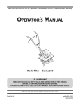
1
Safe Operation
Practices • Set-Up • Operation
• Maintenance
• Service • Troubleshooting
• Warranty
L
World Tiller m Series 210-240
MTD LLC, P.O. BOX 361131 CLEVELAND, OHiO 44136-0019
PrintedIn USA
FormNo.769-05541A
(February04, 2010)
1
ToTheOwner
ThankYou
Thank you for purchasing
an MTD Garden Tiller.
engineered to provide excellent
operated and maintained.
Please read this entire manual
It instructs
performance
It was carefully
prior to operating
your machine.
persons
who will operate
address and mailing
carefully
and
follow
concerning
address can be found
to ensure your complete
Please be sure that you, and any other
the machine,
or questions
Throughout
the
machine
satisfaction
this manual,
are observed
on this page. We want
at all times.
all references
to right and left side of the
from the operating
position
recommended
safety practices at all times. Failure to do so could
result in personal injury or property damage.
The engine
All information
is relative to the most recent
warranty
at the time of printing.
Owner's/Operator's
Manual, packed separately
machine, for more information.
product
in this manual
information
available
the machine,
phone your local authorized MTD service dealer or contact us
directly. MTD's Customer Support telephone
numbers, website
the equipment.
you how to safely and easily set up, operate
maintain
If you have any problems
when properly
manufacturer
is responsible
issues with regards to performance,
Review
this manual frequently to familiarize yourself with the machine,
its features and operation.
Please be aware that this Operator's
for all engine-related
power-rating,
and service. Please refer to the engine
specifications,
manufacturer's
with your
Manual may cover a range of product specifications
for various
models. Characteristics
and features discussed and/or illustrated
in this manual
may not be applicable
the right to change
equipment
without
to all models. We reserve
product specifications,
designs and
notice and without
incurring obligation.
Table of Contents
Safe Operation
Practices ........................................
3
Assembly
Controls
& Set-Up ..................................................
....................................................................
7
9
Operation
................................................................
10
RecordProductinformation
Before setting
up and operating
information
in the provided
area to the right. You can locate
will be necessary, should you seek technical
via our web site, Customer
authorized service dealer.
Support
Troubleshooting
.....................................................
Illustrated
Parts List ...............................................
15
16
71F1F1F1F1F1F1F1F1
please
and record the
the model plate by standing at the operator's position and
looking down at the rear of the tine shield near the handle. This
information
12
14
MODEL NUMBER
your new equipment,
locate the model plate on the equipment
Maintenance
&Adjustment.
.................................
Service .....................................................................
Department,
SERIAL NUMBER
support
EEEEEEEEEEE
or with a local
CustomerSupport
Please
do NOT return
If you have difficulty
this machine,
the machine
assembling
to the retailer
this product
you can seek help from
or dealer
without
or have any questions
the experts.
Choose
from
first contacting
regarding
the options
the controls,
below:
Visit us on the web at www.mtdproducts.com
Call a Customer
Write
Support
Representative
at (800) 800-7310
to MTD LLC • EO. Box 361131 • Cleveland,
or (330) 220-4683
OH • 44136-0019
our Customer
operation,
Support
Department.
or maintenance
of
2
importantSafeOperationPractices
WARNING!
This symbol
could endanger
all instructions
points
the personal
safety and/or
in this manual
with these instructions
out important
before
property
attempting
may result in personal
When you see this symbol.
safety instructions
of yourself
to operate
which,
if not followed,
and others.
this machine.
Read and follow
Failure to comply
injury.
HEED ITS WARNING!
CALIFORNIA
PROPOSITION
65
WARNING! Engine Exhaust, some of its constituents,
and certain vehicle components
contain or emit chemicals known to State of California to cause cancer and birth defects
or other reproductive
,A
WARNING!
Battery
compounds,
harm.
posts, terminals,
chemicals
known
and related
accessories
to the State of California
contain
lead and lead
to cause cancer and reproductive
harm. Wash hands after handling
DANGER! This machine
this manual.
operator
was built to be operated
As with any type of power
according
equipment,
carelessness
can result in serious injury. This machine
toes and feet. Failure to observe
the following
to the safe operation
is capable
practices
in
or error on the part of the
of amputating
safety instructions
fingers,
hands,
could result in serious
injury or death.
Training
1.
2.
Read, understand,
machine
all instructions
and in the manual(s) before
assemble
future
and follow
and operate.
and regular
attempting
Keep this manual
reference
on the
to
in a safe place for
and for ordering
replacement
3.
Be familiar with all controls and their proper operation.
Know how to stop the machine and disengage them
Never allow children under 14 years of age to operate this
machine. Children 14 and over should read and understand
the instructions
and safe operation
and on the machine
adult.
4_
5.
and be trained
small children
area.
in this manual
and supervised
by an
this machine
without
proper
clear of all persons, particularly
and pets. Stop machine
if anyone
enters the
Preparation
Thoroughly
Disengage
levers and shift (if provided)
clutch
starting
can be
this machine
in bare
into neutral
the engine.
Never leave this machine
unattended
with the engine
Never attempt
running,
to make any adjustments
except where specifically
operator's
while
engine is
recommended
in the
manual.
SafeHandling 0f 6as01ine:
in handling
injury
or property
gasoline. Gasoline
damage
is extremely
use extreme
flammable
care
and the
vapors are explosive. Serious personal injury can occur when
gasoline is spilled on yourself or your clothes which can ignite.
Wash your skin and change
clothes immediately.
a.
Use only an approved
b.
Never fill containers
gasoline container.
inside a vehicle
or on a truck
or trailer bed with a plastic liner. Always place
containers on the ground away from your vehicle
inspect the area where the equipment
is to
be used. Remove all stones, sticks, wire, and other foreign
objects
injury.
parts. Never operate
To avoid personal
Never allow adults to operate
instruction.
Keep the area of operation
practices
clothes or jewelry
caught in moving
feet or sandals.
running.
5.
quickly.
3.
4.
work shoes and close fitting
slacks and shirt. Loose fitting
('N") before
parts.
2.
Wear sturdy, rough-soled
which
could be tripped
over and cause personal
before filling.
When practical,
e_
equipment
11.
After striking
dispenser
nozzle.
12.
Keep the nozzle in contact
with the rim of the fuel
tank or container
at all times until fueling
opening
complete.
Do not use a nozzle lock-open
Extinguish
all cigarettes,
g.
Never remove
Disengage
is
handles).
device.
all clutch levers (if fitted)
Engine exhaust
indoors.
Never over fill fuel tank. Fill tank to no more than 1/2
of filler
15.
Use caution
when tilling
underground
utilities.
damage
i.
Replace gasoline
j.
If gasoline is spilled, wipe it off the engine and
equipment.
Move unit to another area. Wait 5
before starting
securely.
or fuel container
clothes
3.
4.
6.
while under
damage.
Keep bystanders
Repair any damage
the influence
caution
if anyone
when
Never operate
hard or slippery
the machine
Exercise caution
9.
Look down
Use only attachments
If situations
while
manual
2.
machine
towards
occur which
are not covered
Contact
proper
enters the area.
3.
by the
injury.
in this manual,
Customer
Support
use
for
dealer..
operating
at high transport
Do
speeds on
in safe
to cool at least five minutes
before
operation
with safety devices. Check their
regularly.
Check bolts and screws for proper tightness at frequent
intervals to keep the machine in safe working condition.
inspect
Before cleaning,
machine
repairing,
for any damage.
or inspecting,
stop the engine
and make certain the tines and all moving parts have
stopped. Disconnect the spark plug wire and ground it
on or crossing
hazards or traffic.
and accessories
Never tamper
Also, visually
4.
attachments
Allow a machine
against the engine to prevent
5.
Do not change
the engine.
the engine
The governor
unintended
governor
controls
starting.
settings
or over-speed
the maximum
safe
speed of engine.
or falling.
you.
6.
found
or replace
safety and instruction
labels, as
necessary.
7.
to the instructions
Maintain
in this
Follow this manual
transporting,
for safe loading,
unloading,
and storage of this machine.
and keep feet well away from the tines at all times.
Always refer to the operator's
if the machine
I
approved
order.
storing.
8.
4
and accessories
Failure to do so can result in personal
Keep machine,
working
it is in
and behind and use care when in reverse or
Start the engine according
while the engine is running.
assistance and the name of you nearest servicing
surfaces.
to avoid slipping
for
and operating.
20.
operating
8.
starting
Maintenance & Storage
of
of the handle bars and do not restrain the machine.
Exercise extreme
before
Never pick up or carry machine
parts. Contact with
away from the machine
Stop the machine
the spark plug wire
Inspect thoroughly
19.
Be careful when tilling in hard ground. The tines may catch
in the ground and propel the tiller forward. If this occurs,
pulling
the engine.
Keep all shields, guards, and safety devices in place and
operating properly.
not carry passengers.
10.
it against
disconnect
18.
1.
gravel surfaces. Stay alert for hidden
7.
start making
to till soil
hands and feet.
Never operate this machine without good visibility or light.
Always be sure of your footing and keep a firm hold on the
handles.
letgo
should
stop the engine,
care and good judgement.
operation.
5.
injury.
an unusual noise or
21.
Do not operate machine
alcohol or drugs.
and
If the machine
manufacturer.
Operation
2.
near fences, buildings
Rotating tines can cause property
17.
dryer or other gas appliances.
parts can amputate
hot and can cause a burn. Do
inside
is an open flame, spark or pilot light
as on a water heater, space heater, furnace,
the rotating
area.
an odorless
by attempting
vibration,
and remove any fuel soaked debris.
Do not put hands or feet near rotating
monoxide,
Do not overload machine capacity
too deep at too fast of a rate.
To reduce fire hazards, keep machine free of grass,
leaves, or other debris build-up. Clean up oil or fuel
where there
or
16.
the engine.
Never store the machine
stop
any adjustments,
or in a poorly ventilated
carbon
become
or personal
and ground
spillage
the
gas.
Muffler and engine
not touch.
fuel expansion.
minutes
indoors
contains
14.
neck to allow space for
cap and tighten
(behind
the engine
is hot or running. Allow engine to cool at least two
minutes before refueling.
inch below bottom
Repair
and stop engine
position
the tines, making
Never run an engine
and deadly
1.
disconnect
the engine.
Wait until the tines come to a complete
before unclogging
inspections.
cigars, pipes and other
gas cap or add fuel while
against
before you leave the operating
13.
Never fuel machine
I.
stop the engine,
Thoroughly
inspect the machine for any damage.
the damage before starting and operating.
fl
k.
object,
If this is not possible, then refuel such equipment
on
a trailer with a portable container, rather than from a
sources of ignition.
h.
a foreign
the spark plug wire and ground
gasoline
d_
remove gas-powered
from the truck or trailer and refuel it on the ground.
SECTION 2 --
IMPORTANT SAFE OPERATION
PRACTICES
manual
for important
is to be stored for an extended
period.
details
9.
If the fuel tank has to be drained,
10.
Observe
proper disposal
etc. to protect
11.
do this outdoors.
laws and regulations
the environment.
internal
According to the Consumer Products Safety Commission
(CPSC) and the U.S. Environmental
Protection Agency (EPA),
this product
SparkArrester
for gas, oil,
_
brushcovered
has an Average Useful Life of seven (7) years,
or 130 hours of operation.
Life have the machine
Atthe
inspected
combustion
engine and should
on ARNING!
or near anyThis
unimproved
machine
or grass-covered
land unless the
engine's
exhaust
system is equipped
end of the Average Useful
arrester
meeting
applicable
annually
any).
by an authorized
service dealer to ensure that all mechanical and safety
systems are working properly and not worn excessively.
Failure to do so can result in accidents,
injuries
or death.
Ira spark arrester is used, it should
working
order by the operator.
above is required
not be used
isforest-covered,
equipped with an
with a spark
local or state laws (if
be maintained
in effective
In the State of California
by law (Section
4442 of the California
the
Public
Notice Regarding Emissions
Resources Code). Other states may have similar laws. Federal laws
Engines which are certified to comply with California and federal
EPA emission regulations for SORE (Small Off Road Equipment)
A spark attester for the muffler is available through your
nearest engine authorized service dealer or contact the service
are certified
to operate
department,
may include
the following
Modification
(EM), Oxidizing
Injection
on regular
emission
unleaded
control
apply on federal
gasoline,
and
lands.
RO. Box 361131 Cleveland,
Ohio 44136-0019.
systems: Engine
Catalyst (OC), Secondary
Air
(SAI) and Three Way Catalyst (TWC) if so equipped.
SECTION 2 --
IMPORTANT SAFE OPERATION
PRACTICES
S
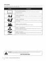
Safety Symbols
This page depicts and describes safety symbols that may appear
machine before attempting
to assemble and operate.
on this product.
Read, understand,
and follow
all instructions
on the
READ THE OPERATOR'S MANUAL(S)
Read, understand,
assemble
and follow
all instructions
WARNING--
WARNING--
WARNING--GASOLINE
parts. Contact with the rotating
parts can amputate
parts. Contact with the rotating
parts can amputate
IS FLAMMABLE
Allow the engine to cool at least two minutes
WARNING-monoxide,
area. Engine exhaust contains carbon
HOT SURFACE
and muffler
the muffler,
become extremely
the use of this power machine
I
SECTION 2 --
IMPORTANT SAFE OPERATION
operation.
Allow engine
to persons who read, understand
in this manual and on the machine.
SAVETHESEINSTRUCTIONS!
6
hot during
to cool before touching.
Your Responsibility--Restrict
and instructions
or in a poorly ventilated
an odorless and deadly gas.
Engine parts, especially
the warnings
before refueling.
CARBON MONOXIDE
Never run an engine indoors
WARNING--
follow
to
ROTATING TINES
Do not put hands or feet near rotating
hands and feet.
WARNING!
attempting
ROTATING TINES
Do not put hands or feet near rotating
hands and feet.
A
in the manual(s) before
and operate
PRACTICES
and
3
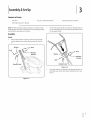
Assembly& Set-Up
Contents of Carton
OneTiller
One 20 oz. bottle
One Engine Operator's
NOTE:The
tiller is shipped
before
operating
One Tiller Operator's
Manual
Manual
without
Fill up gasoline and oil as instructed
manual
SAE 30W oil
gasoline
or oil in the engine.
in the accompanying
2.
engine
Position
the upper
handle onto the lower handle,
Step A in
Fig. 3-2. Align the holes on the lower handle with the holes
your machine.
on the upper handle.
Assembly
Handle
1.
Remove the handle crank, bolt, washer, retainer
bracket
and the flange lock nuts from
3-1.
See Fig.
the lower handle.
Washer
Bolt
Nuts
1
Nuts
Bracket
Retainer
Bracket
Bolt
Handle
Handle
Crank
Crank
Figure 3=2
3.
\\
Insert bolt, washer, and handle crank through the holes in
the handle and secure with retainer bracket and nuts. See
Fig.3-2.
Figure 3-1
4. Insert
theclutch
cablehandle
fittingintotheholeonthe
rightsideoftheupper
handle.
SeeFig.3-3.
Set-tip
(;as & 0il Fill-Up
Service the engine
separate engine
instructions
with gasoline and oil as instructed
manual
in the
packed with your tiller. Read the
carefully.
WARNING!
Use extreme
care when
handling
gasoline. Gasoline is extremely flammable
and the
vapors are explosive. Never fuel machine indoors or
while
the engine
is hot or running.
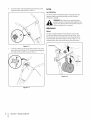
Adjustments
Wheels
The tiller is shipped
with the wheel adjusted
such that the
unit sits level. Before tilling, the wheel must be raised. To do
this, remove the clevis and cotter pins, raise the wheel to the
desired
position,
transporting
Figure
5.
pins to secure, Figure 3-5. For
3-3
Insert the Z-fitting
on the clutch cable into the hole on the
tine clutch control.
Hook the "Z" end into the opening
the inside to the outside
then reattach
the tiller, reverse the steps to lower the wheel.
from
as shown in Fig. 3-4.
Figure
Figure 3-4
8
I
SECTION3--
ASSEMBLY&
SET-UP
3-5
4
Controls
and Features
Tine Clutch
Recoil Starter
Clutch
Cable
Handlebar
Height
Adjustment
De!
Rea r Wheel
Figure 4-1
TineClutchControl
The clutch control
Squeezing
RearWheelwith DepthStake
lever is located
the lever against
on the upper
the handle engages
The rear wheel can be raised and lowered
handle.
storage.
the tine drive.
Refer to the Maintenance
instructions
Release the lever to stop the tines from turning.
on depth stake adjustment
Up Section for instructions
for transport
& Adjustments
and
Section for
and the Assembly
& Set-
on wheel adjustment.
Handlebar HeightAdjustment
The handlebar
height
is adjustable
general, adjust
the handlebars
to three different
In
Refer to the engine manual for additional
functions of the engine controls.
RecoilStarter
Throttle Control (If Equipped)
manually
is located
on the engine
level when the
EngineControls
tines are 3-4" in the ground.
The recoil starter
so they are at waist
settings.
The throttle
and is used to
engine's
start the engine.
stake acts as a brake for the tiller and controls
depth and speed at which
lever is located
on the engine.
and
It controls
the
speed and stops the engine.
ChokeControl
Depth Stake
The depth
control
information
the machine
will operate.
the
Thechoke controlis foundon the rearof the engineand is activatedby pullingthe knobout. Activatingthe chokecontrolcloses
thechoke plateon the carburetorand aids instartingthe engine.
Operation
WARNING! Read, understand, and follow all
instructions and warnings posted on the machine
and in this manual before operating.
WARNING! Be sure no one other than the operator
is standing near the tiller while starting the engine
or operating the unit. Never run the engine indoors
or in enclosed, poorly ventilated areas. Engine
exhaust contains carbon monoxide, an odorless and
deadly gas. Keep hands, feet, hair and loose clothing
away from any moving parts on the engine and the
tiller.
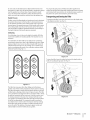
The working depth of the machine may be predetermined by
setting the depth stake so that the wheels are about four inches
from the ground when the tines and depth stake are resting on
the ground. This setting will permit a working depth of about
four inches. When presetting the working depth, the handles
should be adjusted so the hand grips are a little above the waist.
The tiller will be lower when the tines and depth stake penetrate
the ground.
For tilling, the depth stake must be lowered and the wheel must
be raised. See Fig. 5-1.
f
//
StartingEngine
the
tiller whileBethe
engine
is running
or being
WARNING!
sure
no one
is standing
in front of
started.
i_ll
Refer to the engine manual for instructions.
1.
Attach the spark plug wire to the spark plug. Make sure the
metal cap on the end of the spark plug is fastened securely
over the metal tip on the spark plug.
2.
Make sure that the tine clutch control is disengaged.
3.
Place the throttle control (if equipped) in the FASTposition.
4.
For first time start-up, firmly press engine primer five (5)
times. For all future starts, press three (3) times. Wait about
two seconds between each press.
5.
Place your left hand on the gas tank. Grasp the recoil starter
and pull the rope out slowly until the engine reaches the
beginning of its compression cycle (rope will pull slightly
harder at this point).
6.
Pull the rope with a rapid, continuous, full arm stroke. Keep
a firm grip on the handle. Let the rope rewind slowly. Do
not let the recoil starter snap back against the engine.
Repeat until the engine starts.
Figure 5-1
When tilling, leave approximately
eight inches of untilled soil
between the first and second tilling paths, then make the third
path between
the first and second.
See Fig. 5-2.
f
Stopping Engine
1.
Move the throttle control lever (if equipped) to STOPor
OFF position. Refer to the engine manual for instructions
on stopping the engine.
2.
Disconnect the spark plug wire from the spark plug and
ground against the engine.
UsingYourTUler
Your tiller is designed
furrowing,
for seed bed preparation,
cultivating,
and mulching.
Controlling Tilling and Depth Speed
By increasing the depth of the depth stake, the forward speed
of the machine is reduced and the working depth is increased.
When the depth stake is raised, the working depth of the
machine is reduced and the forward speed is increased.
Figure 5-2
In some soils, the desired depth is obtained the first time over
the garden. In other soils, the desired depth is obtained by going
over the garden two or three times. Passesshould be made
across the length and width of the garden alternately. Rocks
which are turned up should be removed from the garden area.
control
by variation
of tilling
depth and travel speed can be obtained
of pressure on the handles. A downward
on the handles will reduce the working
forward
decaying
action,
fertilizer
in with the mulch materials.
should
be applied
Breaking
and
up leaves and straw
and mixing it with several inches of soil allows proper aeration
the plant root system and retards the growth
of
of weeds.
speed. An upward
pressure
pressure
To transport
to the highest
the tiller, lower the wheel and move the depth
position.
stake
See Fig. 5-4.
depth and increase the
on the handles will increase
the working depth and reduce the forward
soil and working conditions will determine
the depth
worked
Transportingand Storingthe TUler
Handle Pressure
Further
For proper
speed. The type of
the actual setting of
stake and the handle pressure required.
Cultivating
For cultivating,
a two to three inch depth
outer tines installed,
24 inches.
For cultivation,
removing
the working
the tine width
width
is desirable.
With the
of the machine
can be reduced
is 22 or
to 13 inches by
the outer tines, refer to the Adjustment
Section. When
laying out plant rows, be sure to allow enough width to permit
cultivation
between the rows. In growing corn or similar crops,
check-row
eliminate
planting
will permit
hand hoeing,
cross cultivation
and practically
Fig. 5-3.
J
Figure 5-4
To store the tiller, lower the wheel and orient the depth stake so
both are touching
k_
the ground.
See Fig. 5-5.
_.)
Figure 5-3
The tiller has many uses other
garden.
than tilling
One of these is the preparation
and cultivating
a
of lawn area for seeding.
The tiller will prepare a deep seed bed which will be free of hard
untilled
spots, allowing
a better
stand of grass to grow. The tiller
is very useful for loosening hard soil for excavation with a shovel;
No tedious handwork will be necessary. Your tiller may be used
for mixing
compost
in the pile or for mixing
your garden. This should
to the full working
it with the soil in
J
Figure 5-5
be done after the soil has been broken
depth. The compost
should
be worked
in
to a depth of six to seven inches. This may be done by working
the length of the garden and then by making separate passes
across its width. The addition
substantially
of decayed
increase the fertility
organic
matter
will
of your garden.
SECTION
S --
OPERATION
11
6
Maintenance& Adjustments
WARNING!
Before inspecting,
cleaning
or servicing
the tiller, shut off the engine and wait for all moving
parts to come to a complete
stop. Disconnect
spark plug. Failure to follow
these instructions
properly
can result in serious personal
property
damage.
injury
the
or
Wheel Shaft
Remove wheel assembly
once a season.
the axle shaft at least
Adjustments
TineWidth (Model Series240)
Maintenance
The tilling
Engine
Refer to the Engine Operator's
machine
and lubricate
for all engine
Manual
packaged
with your
maintenance.
width
of the unit is 22 inches. Tilling width
with the pins. For cultivation,
by removing
reduce the tine width
the outer tines completely.
See Fig. 6-I.
Changingthe Engine Oil
I.
2.
Run the engine fora few minutes to allow the oil in the
crankcase to warm up. Warm oil will flow more freely and
carry away more of the engine sediment which may have
settled at the bottom of the crankcase. Use care to avoid
burns from hot oil.
Pin
Clevis
Pin
Set the tiller on its side with the air filter on the top side
and the oil fill tube facing the ground.
3.
Place an appropriate
oil collection container with at least a
20 fluid ounce capacity to collect the used oil beneath the
oil fill tube.
4.
Remove the oil fill cap/dipstick
5.
After the oil has finished
6.
Refill the engine with new oil. Refer to the Briggs & Stratton
Owner's Manual for information
regarding the volume and
weight
from the oil fill tube.
draining,
_.------
light coat of oil or silicone to prevent
instead of
and apply a
rusting or water damage.
NOTE: Never use a pressure washer to clean the tiller. Water can
tight areas of the tiller and cause serious damage.
Air Filter
Service the air filter every 10 hours under normal operating
conditions.
Clean every hour under extremely dusty conditions.
Poor engine performance
and flooding usually indicates that the
air filter should be serviced. To service the air filter refer to the
Engine Operator's
Manual.
Lubrication
Transmission
The transmission
is pre-lubricated
and sealed at the factory. It
requires no maintenance.
See an authorized
service dealer for
any service issues.
Tine Shafts
Remove tine assemblies
once a season.
13-i nch.-------_
of the tine shield after each use. The dirt
washes off the tines easier if rinsed off immediately
after it dries. Always towel dry the tiller afterwards
penetrate
2=i nc h-------_
of engine oil.
Clean the underside
separate
_.,e--_2
stand the tiller back up.
Tines
and lubricate
the tine shafts at least
can
increase to 24 inches by removing the clevis and cotter pins,
sliding each outer tine out one inch, and securing in this position
Figure 6-1
-
to 13 inches
DepthStake
The depth stake acts as a brake for the tiller and controls the
depth and speed at which the machine will operate, Figure 6-2.
Remove the clevis and cotter
then reattach
pins, raise or lower the depth
stake,
pins to secure.
Figure 6-2
Off-SeasonStorage
If the tiller will not be used fora period
following
steps should
Clean the exterior
thoroughly.
Lubrication
longer than 30 days, the
be taken to prepare the tiller for storage.
of the engine and the entire tiller
Lubricate the tiller as described
instructions.
We do not recommend
in the
the use of pressure washers to
clean your tiller. They may cause damage
to spindles,
pulleys, bearings, or the engine. The use of pressure
washers will result in shortened life and reduce
serviceability.
Refer to the engine manual
instructions.
for correct
Wipe tines with oiled rag to prevent
engine storage
rust.
Store tiller in a clean, dry area. Do not store next to
corrosive materials, such as fertilizer.
When storing
unventilated
to rustproof
any type of power equipment
in an
or metal storage shed, care should be taken
the equipment.
Using a light oil or silicone,
coat the equipment
and cables.
and especially
any springs,
bearings,
SECTION 6 --
MAINTENANCE
& ADJUSTMENTS
13
7
Service
2.
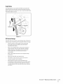
Belt Replacement
Your tiller has been engineered
with a belt made of special
material for longer life and better performance.
Replace with
a factory-approved
purchased
your tiller, an authorized
1-800-800-7310
1.
OEM belt. See the retailer
for information
Loosen the lock nut shown in Fig. 7-2.
Lock Nut
from which you
MTD Service Dealer, or call
regarding
price and availability.
Remove the belt cover and engine by removing the six
screws and lock nuts holding the engine and cover to the
shield. See Fig. 7-1.
Figure 7=2
3_
Unloop
4.
Reassemble
the belt from the pulleys.
5.
Reattach
removed
See Fig. 7-2.
the new belt and tighten
belt cover and engine
earlier.
the lock nut.
using the hardware
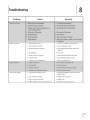
Troubleshooting
Problem
Engine runs erratic
Cause
l
Remedy
1. Spark plug wire loose
1. Connect and tighten
2. Unit running
2. Move choke lever to OFF
on CHOKE
3. Blocked fuel line or stale fuel
spark plug wire
3. Clean fuel line; fill tank with clean, fresh
gasoline
Tines do not engage
4. Vent plugged
4. Clear vent
5. Water or dirt in fuel system
5. Drain fuel tank. Refill with fresh fuel
6. Dirty air cleaner
6. Clean following
engine manual
7. Carburetor
7. Refertoengine
manual
out of adjustment
1. Foreign object
lodged in tines
1. Stop tiller completely,
foreign
checkand
2. Tine clevis pin(s) missing
2. Replace tine clevis pin(s)
3. Belt worn and/or
3. Replace belt
stretched
4. Pulley and idler not in correct adjustment
discard
object
4. Take unitto
authorized
service
15
9
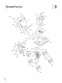
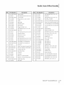
illustratedPartsList
43_
13
I
38
2
51
37
18
29
30
26A
Handle,Frame& WheelAssembly
Ref,
I
Part
Number
1
649-04030-0638
2
710-0136
3
649-04029-0638
Description
Ref, [
Part
Upper Handle
29
710-1007
Self Tapping
Hex Head Cap Screw, 1/4-20x 1.75
30
911-0415
Clevis Pin
Lower Handle
31
710-0809
Self Tapping
737-04272
Pipe Plug, 1/4-18NPT
Description
Number
Screw, 3/8-16 x 1.50
Screw, 1/4-20x 1.25
4
710-04398
Flange Screw, sA6-18x 7.5, GR5
32
5
954-04123
V-Belt
33
642-0002-0637
Inner Tine Assbly RH (model 240)
6
756-04163
Idler Pulley
34
642-0004-0637
Outer Tine Assbly RH (model 240)
35
918-04276B
Case Assembly
61 cm (model
918-04271B
Case Assembly
40 cm (model 210)
7
748-04125
Shoulder
8
686-04080
Idler Bracket
9
712-04065
Flange Lock Nut, 3/8-16
36
721-04157
Gasket
10
710-0654A
Self Tapping
37
786-04296-0637
Wheel Bracket
11
786-04303-0638
Belt Cover
38
712-04063
Flange Lock Nut, sA6-18
12
710-0514
Hex Head Cap Screw, 3/8-16x 1.00
39
710-0189
Hex Head Cap Screw, sA6-18 x 3.00
13
732-0418
Extension
4o
936-0300
Flat Washer, .406 x .875 x .059
41
712-0324
Hex Lock Nut, 1/4-20
42
720-0269
Handle Grip
43
720-0274
Grip, 1.0 ID x 5.0 LG
44
647-04047-0638
Clutch Bail
Spacer
Screw, 3/8-16x 1.00
Spring
14
738-04139
Stud, 33 x 1.5, 3/8-16
15
756-04217
Flywheel
16
710-0591
Hex Head Cap Screw, 3/8-24x 1.00
Pulley
17
710-0520
Hex Head Cap Screw, %-16 x 1.55
18
786-04256-0638
Tine Shield 61 cm (model
240)
45
731-05095B
Bail Holder LH
786-04259-0638
Tine Shield 40 cm (model 210)
46
731-05096B
Bail Holder RH
Clevis Pin
47
731-05272
Handle Fitting
48
736-0242
Bell Washer, .340 x .872 x .060
49
936-0463
Flat Washer, .25 x .630 x .0515
19
911-0415
2O
642-0005-0637
Outer Tine Assbly LH (model 240)
21
642-0003-0637
Inner Tine Assbly LH (model 240)
22
714-04043
Cotter Pin, Bow Tie
5o
946-04663
Clutch Cable
786-0340A
Handle Crank
240)
23
749-04266-0637
Rear Wheel Tube
51
24
714-3020
Cotter Pin
52
786-0341
Retainer
25
726-0299
Push Cap
53
642-04032-0637
Tine Assembly
RH (model
210)
54
642-04031-0637
Tine Assembly
LH (model
210)
55
936-0504
Wave Washer, .510 x .750 x .017
56
736-3069
Flat Washer, .531 x .875 x .15
26A
734-0973
Wheel 5 x 1.38 (model
240)
26B
734-031322
Wheel 6 x 1.50, Steel (model 210)
27
749-04265-0638
Depth Stake Tube
28
711-04520
Axle Shaft
SECTION
9
--
Bracket
ILLUSTRATED
PARTS
LIST
17
1
SECTION10-
NOTES
19
MANUFACTURER'S
LiMiTED WARRANTY
The limited warranty set forth below is given by MTD LLC with
respect to new merchandise purchased and used in the United States
and/or its territories and possessions, and by MTD Products Limited
with respect to new merchandise purchased and used in Canadaand/
or its territories and possessions (either entity respectively, "MTD").
"MTD" warrants this product (excluding its Normal Wear Parts and
Attachments as described below) against defects in material and
workmanship for a period of two (2) years commencing on the date
of original purchase and will, at its option, repair or replace, free of
charge, any part found to be defective in materials or workmanship.
This limited warranty shall only apply if this product has been
operated and maintained in accordance with the Operator's Manual
furnished with the product, and has not been subject to misuse,
abuse, commercial use, neglect, accident, improper maintenance,
alteration, vandalism, theft, fire, water, or damage because of other
peril or natural disaster. Damage resulting from the installation or use
of any part, accessory or attachment not approved by MTD for use
with the product(s) covered by this manual will void your warranty as
to any resulting damage.
Normal Wear Parts are warranted to be free from defects in material
and workmanship for a period of thirty (30) days from the date of
purchase. Normal wear parts include, but are not limited to items
such as: batteries, belts, blades, blade adapters, tines, grass bags,
wheels, rider deck wheels, seats, snow thrower skid shoes, friction
wheels, shave plates, auger spiral rubber and tires.
Attachments-- MTD warrants attachments for this product against
defects in material and workmanship for a period of one (1) year,
commencing on the date of the attachment's original purchase or
lease. Attachments include, but are not limited to items such as:
grass collectors and mulch kits.
HOWTO OBTAINSERVICE:Warranty service is available, WITH
PROOFOF PURCHASE,through your local authorized service dealer.
To locate the dealer in your area:
In the U.S.A.
Check your Yellow Pages, or contact MTD LLC at RO. Box 361131,
Cleveland, Ohio 44136-0019, or call 1-800-800-7310, 1-330-2204683 or log on to our Web site at www.mtdproducts.com.
In Canada
Contact MTD Products Limited, Kitchener, ON N2G4J1, or call 1-800668-1238 or log on to our Web site at www.mtdcanada.com.
This limited warranty does not provide coverage in the following
cases:
a. The engine or component parts thereof. These items may carry a
separate manufacturer's warranty. Referto applicable manufacturer's warranty for terms and conditions.
b. Log splitter pumps, valves, and cylinders havea separate oneyear warranty.
FOR
c. Routine maintenance items such as lubricants, filters, blade
sharpening, tune-ups, brake adjustments, clutch adjustments,
deck adjustments, and normal deterioration of the exterior finish
due to use or exposure.
d. Service completed by someone other than an authorized service
dealer.
e. MTD does not extend any warranty for products sold or exported
outside of the United States and/or Canada, and their respective
possessions and territories, except those sold through MTD's
authorized channels of export distribution.
f. Replacement parts that are not genuine MTD parts.
g. Transportation charges and service calls.
h. MTD does not warrant this product for commercial use.
No implied warranty, including any implied warranty of
merchantability of fitness for a particular purpose, applies after
the applicable period of express written warranty above as to the
parts as identified. No other express warranty, whether written or
oral, except as mentioned above, given by any person or entity,
including a dealer or retailer, with respect to any product, shall
bind MTD. Duringthe period of the warranty, the exclusive remedy
is repair or replacement of the product as set forth above.
The provisions as set forth in this warranty provide the sole and
exclusive remedy arising from the sale. MTD shall not be liable
for incidental or consequential loss or damage including, without
limitation, expenses incurred for substitute or replacement lawn
care services or for rental expenses to temporarily replace a
warranted product.
Some states do not allow the exclusion or limitation of incidental
or consequential damages, or limitations on how long an implied
warranty lasts, so the above exclusions or limitations may not apply
to you.
In no event shall recovery of any kind be greater than the amount of
the purchase price of the product sold. Alteration of safety features of
the product shall void this warranty. You assume the risk and liability
for loss, damage, or injury to you and your property and/or to others
and their property arising out of the misuse or inability to use the
product.
This limited warranty shall not extend to anyone other than the
original purchaser or to the person for whom it was purchased as a
gift.
HOWSTATELAW RELATESTO THIS WARRANTY: This limited
warranty gives you specific legal rights, and you may also have other
rights which vary from state to state.
IMPORTANT: Owner must present Original Proof of Purchase to
obtain warranty coverage.
MTD LLC, P.O. BOX 361131 CLEVELAND, OHiO 44136=0019; Phone: 1=800=800=7310, 1=330=220=4683
MTD Canada Limited = KITCHENER, ON N2G 4J1; Phone 1=800=668=1238
GDOC-lO0015 REV. B