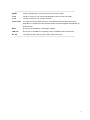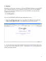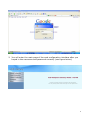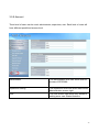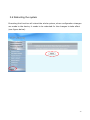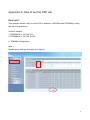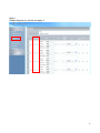
1
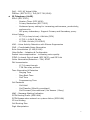
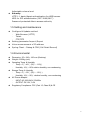
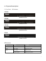
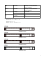
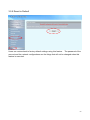
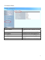
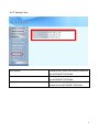
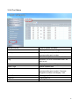
User’s Manual IP Telephony Gateway Model No.: SP5108A, SP5058A, SP5008A, SP5208 1. Introduction ................................................................................................. 3 1.1 VoIP Gateway .........................................................................................................3 1.2 Key Features ..........................................................................................................3 1.3 Physical Interface ...................................................................................................4 1.4 Specification ...........................................................................................................4 1.5 Setting and maintenance ........................................................................................6 1.6 Environmental.........................................................................................................6 2. Physical Description.................................................................................... 7 3. Startup....................................................................................................... 10 3.1 Configuration ........................................................................................................10 3.2 Network Configuration ..........................................................................................13 3.2.1 WAN Setting .............................................................................................................13 3.2.1.1 WAN Setting --Static IP .........................................................................................18 3.2.1.2 WAN Setting --DHCP ............................................................................................19 3.2.1.3 WAN Setting --PPPoE ...........................................................................................20 3.2.2. LAN Setting .............................................................................................................21 3.3 General configuration ...........................................................................................23 3.3.1 PABX Mode (Micronet SP5018A) ...........................................................................23 3.3.2 SIP Setting.................................................................................................................25 3.3.3 SIP Advanced Setting................................................................................................28 3.3.4 Payload Type Setting.................................................................................................31 3.3.5 Line Setting ...............................................................................................................32 3.3.6 Qos Setting................................................................................................................35 3.3.7 Speed Dial Setting.....................................................................................................37 3.3.8 Caller ID Setting .......................................................................................................38 3.3.9 CDR Setting ..............................................................................................................40 3.3.10 Syslog Setting .........................................................................................................42 3.4 Advanced Configuration........................................................................................44 3.4.1 System setting ...........................................................................................................44 3.4.2 SNTP Setting.............................................................................................................49 3.4.3 Codec Setting ............................................................................................................50 3.4.4 Voice Setting .............................................................................................................52 3.4.5 Tone Setting ..............................................................................................................54 3.4.6 Phone Setting ............................................................................................................56 3.4.7 Digit Manipulation....................................................................................................58 1 3.4.8 Dial Plan....................................................................................................................60 3.4.9 Call routing Editor ....................................................................................................62 3.5 Management.........................................................................................................63 3.5.1 Provision Server........................................................................................................63 3.5.2 Save-Reload setting...................................................................................................66 3.5.3 Voice File ..................................................................................................................67 3.5.4 Upgrade Firmware ....................................................................................................68 3.5.5 Reset to Default.........................................................................................................69 3.5.6 Network Status..........................................................................................................70 3.5.7 Version Info...............................................................................................................71 3.5.8 Port Status .................................................................................................................72 3.5.9 Account .....................................................................................................................73 3.6 Rebooting the system ...........................................................................................74 Appendix A: How to set the P2P call............................................................. 75 2 1. Introduction 1.1 VoIP Gateway Micronet SP5008A / SP5018A / SP5058A are high-capacity SIP Gateway Series that provides 8 FXS / 4 FXS + 4 FXO / 8 FXO ports, and suit to build an IP-based communication platform with other VoIP devices. They meet enterprise’s requirement for functionality (VoIP) upgrade and larger scale implementation by interoperating with legacy PABX and IP PBX/Soft-switch. To connect with legacy PABX, SP5018A supports PABX Mode for PSTN backup. When network or power fails, PSTN lines (FXO) bypass to FXS ports and users still can make/receive calls via PSTN lines. SP5008A includes some wonderful PABX features for small business. They help operate users on various VoIP applications, such as extension calling among 8 FXS ports, inbound/outbound calls via SIP trunk, DID (direct line), DOD, prefix routing, operator attendant, etc. Users can easily benefit from the ease-to-use device. SP5208 supports 2 FXO ports to connect with PSTN lines which are subscribed for company’s representative telephone number. By just connecting FXO ports, users can make/receive calls via PSTN lines with default configuration. Company with IP-based platform still can receive daily phone calls from PSTN or GSM, if the direct calling with PSTN number to VoIP network is not supported by ITSP/ISP. SP5208 also provides PSTN backup by FXO connections, even if power or network fails. With the smart designs, SP5208 is a perfect VoIP solution to small business customers. 1.2 Key Features z z z z z z z z z IETF SIP standards compliant Support 1 RJ-45 WAN port and 4 RJ-45 LAN ports Support POTS interfaces: 8 FXS / 4 FXS + 4 FXO / 8 FXO ports Support single-account registration on FXS ports for representative number Support extension calling among FXS ports Support rich call features: call hold, call transfer, call forward, hotline, warm line, speed dial, anonymous call, P2P call, etc Support PSTN prefix routing (SP5018A only) Support PABX mode for legacy PABX function upgrade (SP5018A only) Support PSTN lifeline – PSTN bypass in case of power or registration failure (SP5018A only) 3 z z Support detection of disconnect tone, polarity reversal, and loop current drop (zero voltage) on FXO ports Well interoperability with industry-leading IP-PBX/Soft-Switch, such as Alcatel, Lucent, Siemens, etc. 1.3 Physical Interface z z z z z Ethernet port (RJ-45, 10/100 base-T) WAN port, for connect to router, ADSL modem (ATU-R), or switch hub directly. 4-LAN port, for PC or other network devices connecting. Telephony port (RJ-11) --- depending on different models 8-FXS ports, to connect with analog phone 8-FXO ports, to connect with PSTN 4-FXO/4FXS ports, to connect with PSTN and analog phone 4 FXO ports, to connect with PSTN 4 FXS ports, to connect with phone Reset button (Factory Default) AC power Jack Status indicated LED Indicates Ethernet, FXS, and SIP system status 1.4 Specification z IP Network connection IPv4 (RFC 791) MAC Address (IEEE 802.3) PPPoE Client (RFC 2516) DNS Client DHCP Client (RFC 2131) DHCP Server (RFC 2131) NAT (RFC 1631) TCP/UDP (RFC 793/768) ICMP (RFC 792) RTP/RTCP (RFC 1889/1890) SNTP (RFC 2030) TFTP Client Telnet Server HTTP Server 4 z QoS – 802.1Q Virtual LANs DiffServ (RFC 2475) / ToS (RFC 791/1349) IP Telephony (VoIP) SIPv2 (RFC 3261) Session Timer (RFC 4028) Privacy Mechanism (RFC 3323) Outbound proxy setting for increasing performance, productivity, and security. SIP proxy redundancy- Support Primary and Secondary proxy. Voice Codecs G.711 (a-Law/u-Law): 64k bits (PCM) G.723.1: 6.3k/5.3k bits G.729A: 8k bits (CS-SCELP) VAD – Voice Activity Detection with Silence Suppression CNG – Comfortable Noise Generation Echo Cancellation (G.165/G.168) Jitter Buffer – Adaptive & Configurable Packet Loss compensation - increasing voice quality DTMF: In-band, Out-of-band (RFC 2833), and SIP-Info Caller Generation/Detection – FSK, DTMF FAX transmission G.711 pass-through T.38 Fax relay protocol Tone Generation & Detection Ringing Tone Ring Back Tone Dial Tone Programming Tone Call Features Call Hold Call Transfer (Blind & consultant) Call Forward (Unconditional / No Answer / Busy) MWI – Message Waiting Indication PSTN Routing Prefix (SP5018A) PSTN Bypass when network or system failure (SP5018A) IP line hunting Call Routing Plan Digit Manipulation 5 z Adjustable volume level Security HTTP 1.1 basic/digest authentication for WEB access MD5 for SIP authentication (RFC 2069/2617) Password protected Admin access authority 1.5 Setting and maintenance z z z z Configure & Update method Web Browser (HTTP) Telnet FTP/TFTP Setting parameter Import /Export Voice announcement of IP address Syslog Client – Debug & CDR (Call Detail Record) 1.6 Environmental z z z Dimension: 35 × 242 × 160 mm (Desktop) Weight: 0.935kg (unit) Operating Temp. & Humidity Temp.: 0℃~45℃ (32℉~113℉) Humidity: 10%~85% relative humidity, non-condensing z Storage Temp. & Humidity Temp.: 0℃~55℃ (32℉~131℉) Humidity: 10%~95% relative humidity, non-condensing z AC Power Adaptor: z INPUT: AC100V-240V, 50/60Hz OUTPUT: DC 12V, 3.0A Regulatory Compliance: FCC (Part 15, Class B) & CE 6 2. Physical Description 2.1 Front Panel: LED Indicators SP5008A: SP5008A Front Panel SP5058A SP5058A Front Panel SP5018A SP5018A Front Panel SP5208 SP5208 Front Panel LED Indicators LED Status Description POWER On / Green The Power is on READY Blink / Green Booting up for self test PROXY Blink / Green Gateway reg. fails Constant / Green Gateway reg. successes 7 WAN Blink / Green Transmitting or receiving data /Network connection established LAN(1-4) Blink / Green Transmitting or receiving data /Network connection established T(1*) L(1*) 1*. On / Orange Busy / Off-hook Off Available / On-hook On / Orange Busy Off Available SP5008A: FXS = T1 - T8 SP5018A: FXS = T1 - T4, FXO = L1 - L4 SP5058A: FXO = L1 - L8 SP5208: FXS = T1 – T6, FXO = L1 – L2 SP5008A SP5008A Rear Panel SP5058A SP5058A Rear Panel SP5018A SP5018A Rear Panel SP5208 SP5208 Rear Panel 8 --------------------------------------------------------------------------------------------------RESET Factory default button. Press and hold for 5 seconds to reset T1-T8 The RJ-11 FXS port 1-8, connects analog phone sets, trunk line in PABX. L1-L8 The RJ-11 FXO port 1-8, connect to PSTN T1/P1-T4/P4 It is a pair of FXO and FXS connector. The different is that the when power off or application is crashed, the FXO and FXS will be connected together automatically for local surviving. WAN RJ-45 port of 10/100M for connecting to modem LAN(1-4) RJ-45 port of 10/100M for connecting to PC or hub/switch that connects PCs DC 12V The power socket, input AC 100V~120V; output DC12V.3A --------------------------------------------------------------------------------------------------- 9 3. Startup First of all, connect your computer to Micronet SP50X8A’s LAN port by using DHCP. The IP address assign to your computer should be 192.168.123.x by default. Once you can get the IP address from Micronet SP50X8A, you can start the configuration as below. 3.1 Configuration Login to the MICRONET SP50X8A web configuration menu 1. Open your WEB browser and key in the default IP address of the gateway (http://192.168.123.123) in the Address box (see figure below). 3. You will see a pop-up window requesting username and password before you can login to the web configuration menu. Username is “root” while password is empty (see figure below). 10 2. You will enter the main page of the web configuration interface after you keyed in the username and password correctly (see figure below). 11 12 3.2 Network Configuration The following instructions will explain the configurations for setting up the WAN port of the SP50X8A. There are in total three methods of connections: Static IP, DHCP and PPPoE. Note: You can retrieve the IP address of the WAN port by keying #126 on the phone set that is connected to the FXS port of the gateway. You will hear an IVR announcing the current IP address of the WAN port. 3.2.1 WAN Setting The table shown below describes the configuration items for 3 connection types of network (Static IP, DHCP and PPPoE). 13 14 WAN Setting Item Description Static IP DHCP PPPoE Connected mode Select the connection method for the WAN port of the SP50X8A, you can choose the following: z Static IP z DHCP z PPPoE V V V Current IP Address Show current IP address V V V DNS server mode Select the DNS behavior, you can choose the following: z Auto z Manual “DNS auto” will retrieve the DNS information sent from the DHCP server. “Manual” will look at the specified Primary and Secondary DNS address. V V V Primary DNS address Specify the address of the Primary DNS. V V V Secondary DNS address Specify the address of the Secondary DNS. V V V WAN Link Speed Select the connection speed for the WAN port of the SP50X8A, you can choose the following: z Auto z 100M z 10M V V V HTTP port for WEB management Specify the port number for WEB management, the allowable range is 80, 1024~65535. V V V Remote Access Web access for WAN port: Disable: no any web access is allowed V V V 15 http: http access only https: https access only both: http and https access are allowed HTTPS port for WEB management The http SSL port (the default is 443), 1024~65535. V IP address Specify the IP address. V Subnet mask Specify the subnet mask. V V V 16 WAN Setting Item Description Default gateway Specify the IP address of the default gateway. V Remote access restriction Restricts/Blocks users connecting to the WAN port’s IP remotely, you can Enable/Disable this option. V PPPoE userID Specify the username of the PPPoE account V PPPoE password Specify the password associated to the PPPoE account above. V When the remote host (PPPoE) fails, the gateway will retry 3 times to reconnect, if there is no reply from the remote host within 3 tries, then the gateway will reboot. You can Enable/Disable this option. V Reboot after remote host disconnection Static IP DHCP PPPoE V V 17 3.2.1.1 WAN Setting --Static IP 1. Press the “Apply” button (at the bottom) after you finish to save changes. 2. Press the “Reboot” button to apply the changes. 18 3.2.1.2 WAN Setting --DHCP 1. 2. Press the “Apply” button (at the bottom) after you finish to save changes. Press the “Reboot” button to apply the changes. P.S. When you are using DHCP in WAN and WAN’s Ethernet cable are not connected, you will not able to access Micronet by using WAN port if you don’t know the DHCP IP address. In this case, please connect to LAN port and access it. 19 3.2.1.3 WAN Setting --PPPoE 1. Input PPPoE user ID and password 2. 3. 4. Press the “Apply” button (at the bottom) after you finish to save changes. Press the “CANCEL” button (next to the Apply button) to clear the values in the page. Press the “Reboot” button to apply the changes. 20 3.2.2. LAN Setting LAN Setting ITEM Description LAN Mode It supports Bridge or NAT mode LAN IP address Specify the IP address of the SP50X8A LAN port. LAN mask address Specify the mask address for SP50X8A LAN port. DHCP server Enable/Disable DHCP function on the LAN port. Once enabled, the LAN ports will function as a DHCP server, network devices connected to them will be issued with IP addresses. IP address from When DHCP is enabled, you can specify the IP address to start from when assigning to attach network devices. IP address to When DHCP is enabled, you can specify the ending IP address assigned to the attached network devices. 21 LAN Setting ITEM Description Domain Name You can specify the domain name that will be assigned by the DHCP server to the attached network devices. The DHCP server will send information on the “server host name” to the DHCP client. Lease time(sec) You can specify the maximum lease time of the IP address allocated to the DHCP client. DNS server mode Select the DNS behavior, you can choose the following: z Auto z Manual “DNS auto” will retrieve the DNS information sent from the DHCP server. “Manual” will look at the specified Primary and Secondary DNS address. Primary DNS address Specify the address of the Primary DNS. Secondary DNS address Specify the address of the Secondary DNS. 1. 2. Press the “Apply” button (at the bottom) after you finish to save changes. Press the “Reboot” button to apply the changes. 22 3.3 General configuration To make VoIP calls, you will need a SIP account provided by the SIP Proxy you are registered with. To configure the relevant SIP settings, please refer to the instructions explained below. 3.3.1 PABX Mode (Micronet SP5018A) This quick setting is dedicated to be used for Micronet SP5018A to become a inter-connection in between PSTN and traditional PABX. The call scenario will be working as below: 1. For FXO incoming call, it will route to corresponding FXS directly (1 by 1) 2. For FXS outgoing call, it will route to VOIP except those prefix set in FXO dialing Prefix. 3. For VOIP incoming call, it will route to FXS based on the called number 4. When VOIP call is failed to be called out such as register fail or network issue, the call will be route to FXO as backup. 5. When Micronet SP50X8A is malfunction or power failure, the all call will be directly bypassed to FXO. 23 PABX Connection To enable PABX behavior or not. SIP Setting Please refer to 3.3.2.1 SIP Trunk Configuration It is used when you only have a SIP account to be shared for FXS lines. Please refer to 3.3.2.1 Primary FXS SIP settings When you have multiple SIP accounts for each FXS line, please set SIP Trunk Number Only to No. Then refer to 3.3.2.1 for the detail FXS SIP Setting FXS line SIP account settings Port Hunting Select the group of SIP Trunk number, and specify the priority. Only the checked line will become the member of the SIP Trunk number. The default setting L1~L2 is grouped. 24 3.3.2 SIP Setting Proxy Redundant Mode Disable: only register to primary proxy. Act-Act: register to primary proxy and secondary proxy simultaneously. The call routing will use primary proxy as the default outbound proxy and only use secondary proxy when the primary one is not registered. The incoming call for both proxy are accepted. Act-Backup: At first, Micronet will register to primary proxy. If it is failed to register to the primary proxy, it will stop the trying and use secondary proxy to register. It will try alternative proxy when the last one is failed. There is only 1 proxy registered at the same time. And once it is registered, it will stop 25 truing. Primary proxy Specify the data of primary proxy: Enable/Disable, IP address, Port#, Domain Name, Expire time and MWI TTL. Secondary proxy Specify the data of secondary proxy: Enable/Disable, IP address, Port#, Domain Name, Expire time and MWI TTL. When you enable secondary proxy, it will start to register no matter whether primary proxy is registered or not. However, it will be used only when primary proxy is not registered or the incoming call is coming from it. Outbound proxy Specify the data of Outbound proxy: Enable/Disable, IP address and Port#. Secondary Outbound proxy Specify the data of Outbound proxy for secondary proxy: Enable/Disable, IP address and Port#. SIP Trunk Number The SIP trunk is working for the selected FXS line (for all FXS or FXO/FXS combination model) or FXO line (for all FXO model). When an incoming call is send to the SIP trunk number, the selected FXS or FXO port will be hunted. Enable Enable the Line, the default setting is “Enable” and it will Register or Unregister to SIP Proxy Account Input the SIP Proxy registration account ID. Number Input the phone number. Password Input the password of IP Proxy registration account ID. Display name Specify the Display name of the phone number Forward Specify the Representative forwarding type to be used, only choose busy Forward Number Specify the number to be forwarded when the specified forward condition is met. 26 Ring Type Select the Ring Type of representative number. You can choose the following: z Serial ring (Follow the ring priority defined below) z Simultaneous(ring all) Ring Time (s) for Serial ring Specify the Ring Time for Serial ring Status Displays the registration status, whether it is registered or not. Port Hunting Select the group of sip trunk number, and specify the priority. Only the checked line will become the member of the sip trunk number. The default setting L1~L2 is grouped. 1. Enter the IP address and port number of the SIP proxy into the Primary proxy address 2. and Port fields. Press the “Apply” button to save changes. Press the “Reboot” button to apply the changes. 27 3.3.3 SIP Advanced Setting Local SIP port(1~65535) Specify the local starting SIP port. Each account’s interval is 2. For example, the local SIP port is set to 5060. The following is the port number to be used for SP50X8A: Port 1: 5060 Port 2: 5062 Port 3: 5064 Port 4: 5066 Port 5: 5068 Port 6: 5070 Port 7: 5072 Port 8: 5074 SIP Trunk Number: 5076 Local RTP port(1~65535) Specify the local starting RTP port number. Session Expire(Sec) Specify the session expire time that will be used to negotiate with the remote host or 28 proxy. Min Session Expire(Sec) Specify the minimum session expire time that other host or proxy will need to follow when calling the MICRONET SP50X8A. Session Refresh Request Select the session refresh method that will be used on the MICRONET SP50X8A, you can choose among the two methods: z UPDATE z Re-Invite Session Refresher Select who will perform the refreshes, you can choose among the two methods: z UAC (Client) z UAS (Server) This will add the parameter refresher=uac or uas in the Session Refresh Request message. Unregister All Send SIP unregister signaling message after the SP50X8A has been restarted RFC 3325 support Enable RFC 3325 for anonymous calling or not. When it is enabled, Micronet will follow RFC 3325 to send the required header. Or the display name and user ID will be changed to “anonymous” when RFC3325 is disabled. Support Message Waiting Indication (MWI) You can Enable or Disable the MWI function.( This feature is for FXS only) SIP Message Resend Timer Base T1 (sec) Specify the resend time in seconds for each SIP request message that has not received a response. Max. Response Time for Invite (1~30sec) Specify the timeout period for SIP Invite messages. For example, if the timeout period is 10 seconds, when the SP50X8A sends an Invite message and does not receive a response within 10 seconds, it will cancel the call. SIP/RTP Encrypt Enable Micronet proprietary encryption for SIP signaling and RTP or not. It is required a Micronet SIP proxy server to work with 29 this feature. When enable it, you can hide your VOIP traffic from ISP’s monitor. SIP session keep mode Select the following NAT SIP session keeping method. z Disable z Empty packet (0x0D and 0x0A will be send) z SIP Options (send SIP option) z SIP Register (send SIP register message) z SIP Ping (send Nortel SIPping) SIP session keep interval (sec) The interval to send the SIP session keep message out. The method was defined in “SIP session keep mode”. NAT traversal setting Support through NAT methods z Disable z IP Sharing: Use DMZ to map the private Micronet IP address to a public one. You need to do the DMZ on IP sharing box. z STUN: Use STUN to do NAT transversal. This method can only work for NAT type 1 and 2. NAT device IP address The DMZ IP address used for IP sharing NAT transversal mode. STUN server The STUN server IP address STUN port The STUN port (default is 3478) Generate tone for 100 trying Whether to generate tone when receive the SIP message 100 trying or not. You can specify to generate the defined ring back tone or a custom tone to be played. Custom Tone Please refer to Tone Settings for the detail of custom tone for 100 trying. 1. 2. Press the “Apply” button (at the bottom) after you finish to save changes. Press the “Reboot” button to apply the changes. 30 3.3.4 Payload Type Setting RFC2833 payload type Specify the RFC2833 payload type (range is 96~128, however 100, 102~105 is reserved by other payload types). FAX bypass payload type Specify the FAX payload type (range is 96~128, however 100, 102~105 is reserved by other payload types) Modem by pass payload type Specify the Modem by pass payload type (range is 96~128, default value is 103. 100, 102, 104, 105 is reserved by other payload types). 1. 2. Press the “Apply” button (at the bottom) after you finish to save changes. Press the “Reboot” button to apply the changes. 31 3.3.5 Line Setting 32 No Answer Forward Time (FXS only) If you enable the No Answer Forward function (sip trunk number or L1~L8 number), please specify the time of no answer. The default setting is 180 sec. FAX Enable/Disable FAX T.38 function. Line1~Line8 relevant data Type Displays the port type of that particular line. Enable Enable the line or not Reg Register or Unregister to SIP Proxy Number Displays the line numbers that specified in SIP Setting. Account: Input the SIP Proxy registration account ID. Number: Input the phone number. Password: Input the password of IP Proxy registration account ID. Display name: Specify the Display name of the phone number. The first is the number registers to Primary 33 proxy. The default setting is 1000~1007. Enable Hotline Click the check box to enable hotline feature. If enabled, The check box will display as . Hotline Number Specify the number to forward the call to when the Hotline feature is enabled. Wait to Hotline(sec) Specify the time (sec) for wait to hotline, the default value is 0. Forward Type (FXS only) Specify the forwarding type to use, you can choose the following: z Disable z Unconditional z Busy z No Answer z Busy and No Answer The “Disable” option will allow you to disable this particular function. Forward Number Specify the number to forward the call to when the call forwarding feature is enabled. Call Waiting (FXS only) Enable/Disable per-line Call Waiting function. DND (FXS only) Enable/Disable per-line DND (Do Not Disturb) function. Greeting (FXO only) Enable/Disable Greeting for FXO Anonymous (FXS only) When this feature is Enabled, the calling number (ANI) will be hided. The hiding method depends on the setting of “rfc3325 support”. (Please make sure your proxy server or soft switch supports the feature, if the proxy does not support it and you enable this feature, all IP outgoing calls will be dropped.) 1. 2. Press the “Apply” button (at the bottom) after you finish to save changes. Press the “Reboot” button to apply the changes. 34 3.3.6 Qos Setting Type Select Qos Type: DSCP or ToS Differentiated Services Code Point Setting (DSCP) DSCP RTP Select the DSCP value for RTP (voice packets), the value in the drop down list is expressed in binary format, you can choose to meet your network environment. DSCP Signal Select the DSCP value for SIP message, the value in the drop down list is expressed in binary format, you can choose to meet your network environment. ToS Setting ToS RTP ToS Signal Select the ToS value for RTP (voice packets), the value in the drop down list is expressed in binary format, you can choose to meet your network environment. Select the ToS value for SIP messages, the value in the drop down list is expressed in binary format, you can choose to meet your 35 network environment. 1. 2. Press the “Apply” button (at the bottom) after you finish to save changes. Press the “Reboot” button to apply the changes. 36 3.3.7 Speed Dial Setting Speed Dial Editor Specify the speed Dial Number/Telephone Number/Name, and then press the Add or Del button to add or delete record (it can set 50 records). 37 3.3.8 Caller ID Setting Caller ID Setting (Line 1~Line 8) Select the (Line 1~Line 8)Caller ID generation type to use, you can choose the following: z Disable z DTMF z FSK(Bellcore) z ETSI(Before Ring) z ETSI(Between ring) FXO only choose Enable/Disable the caller ID detection AUTO: You can choose different caller ID type by line. If Line1~Line8 uses the same type, you only need to set line 1 and click the “Auto” button, then the other lines will set the same type automatically. 38 The “Disable” option will allow you to disable this particular function. DTMF Caller ID Start Symbol Specify the DTMF Caller ID Start Symbol The default symbol is D. DTMF Caller ID End Symbol Specify the DTMF Caller ID End Symbol The default symbol is C. 1. 2. Press the “Apply” button (at the bottom) after you finish to save changes. Press the “Reboot” button to apply the changes. 39 3.3.9 CDR Setting CDR mode Select the CDR mode for Enable or Disable. If you Enable this feature, please specify the CDR Server address and port number at the CDR server address and port’s text box, then you can get Call Detail Data form CDR Server. CDR Server address If you Enable the CDR mode, please specify the IP address of CDR Sever for data storage. CDR Server port Specify the CDR Server port number, The default port number is 514. 1. 2. Press the “Apply” button (at the bottom) after you finish to save changes. Press the “Reboot” button to apply the changes. 40 P.S. To receive the SYSLOG CDR, you need to have a syslogd server to collect the CDR from Micronet SP50X8A. The following is a tool you can be used for testing purpose which can be downloaded from http://tftpd32.jounin.net/. You need to enable syslog server from settings before you can use it. 41 3.3.10 Syslog Setting This syslog is used to send the debug log from Micronet SP50X8A to syslog server. Syslog mode Select the Syslog mode for Enable or Disable. If you Enable this feature, please specify the Syslog Server address and port number at the Syslog server address and port’s text box, then you can get detail system log from Syslog server. Syslog Server address If you Enable the Syslog mode, please specify the IP address of Syslog Sever for data storage. Syslog Server port Specify the Syslog Server port number, The default port number is 514. 1. 2. Press the “Apply” button (at the bottom) after you finish to save changes. Press the “Reboot” button to apply the changes. 42 P.S: To receive the SYSLOG debug information, you need to have a syslogd server to collect the debug information from Micronet SP50X8A . The following is a tool you can be used for testing purpose which can be downloaded from http://tftpd32.jounin.net/. You need to enable syslog server from settings before you can use it. 43 3.4 Advanced Configuration 3.4.1 System setting prack PRACK is defined in RFC 3262: Reliability of Provisional Responses in SIP. You can accommodate your softswitch (Proxy Server) to Enable or Disable this feature. ROH Tone(FXS only) Receiver-Off-Hook (ROH) Tone A ROH tone is sent to the subscriber to inform him that his receiver is off-hook. You can Enable/Disable this option. Enable: using default setting or custom setting. Send billing signal (FXS only) Enable Polarity Reversal for FXS as billing signal or not. When a FXS calls to VOIP and answered by the VOIP, SP50X8A will generate reverse signal to FXS as billing start. When VOIP side disconnect first, SP50X8A will reverse back as billing stop signal. 44 T.38 NoAttribute No attribute (Fax version, Bit Rate, Buffer, Datagram…) indicated in T.38 Re-Invite with Session Description Protocol (SDP). You can Enable/Disable this option. FAX redundancy depth Specify the resend times (0~3)for FAX error packet, T.38 FAX Type Select the FAX Type to use, you can choose the following: z T.38 z ByPass z Auto T.30 FAXByPass Codec Select the FAX ByPass Codec to use, you can choose the following: z G.711 a-law z G.711 u-law Flash key function (FXS only) Select the function of Flash key, you can choose the following: z Disable z Transfer z SIP Message Keypad DTMF type Select the type of Keypad DTMF, you can choose the following: z In-Band z RFC2833 z SIP Info End of dial key Select the End of dial key, you can choose the following: z z z Disable * # DTMF Detection Sensitivity Specify the grade of DTMF Detection Sensitivity, the value range is (1~5) Dial Wait Timeout (1~60sec) Specify the duration of dial waiting when the receiver is off hook. The range is 1~60 sec. Inter Digits Timeout (1~5sec) Specify the interval of input digits, if the interval is over the setting, the system will end the dial and send out the DTMF. The 45 limitation range is 1~5sec. FAXByPass Keyword Some SIP Proxy need specify special keyword for FAXByPass function. Input the data as SIP Proxy required. FAXByPass Keyword Some SIP Proxy need specify special keyword for FAXByPass function. Input the data as SIP Proxy required. IP Address announcement You can Enable/Disable this function, If you select Enable, you can connect T1 port with a phone set and press #120#, you will hear the announcement of IP address of LAN port, or press #126# to get WAN port IP address. FXO please following under step: 1. You can get a PSTN line and connect to the L1 FXO port. 2. Use another PSTN phone to dial the PSTN number (in step 1you connected on FXO-08), you will hear a second dial tone or greeting (please dial extension number). 3. Press #126# on the phone set, and you will hear an IVR announcing the current IP address of the WAN port. 4. Press #120# on the phone set, and you will hear an IVR announcing the current IP address of the LAN port. Built-in Call Hold Music System built-in music of call hold, you can Enable/Disable this feature. DTMF Duration Specify the DTMF tone duration. DTMF Interdigit Time Specify the interval of DTMF digit Ring Time Limit ( 10~600sec ) Specify the limitation of Ring time for incoming call, when the ring is over the limit, system will drop the call. The default range is 10~600sec. (FXS only) Disconnect Singal Detcetion z Disable 46 z Polarity Reversal When enable the Polarity Reversal Detection, SP50X8A (FXO) will use the polarity reversal as the answer signal and polarity normal as the hang-up signal for FXO outgoing call. z Loop Current Drop Use line current drop as the disconnect signal or not. z Both Enable polarity reversal and current drop simultaneously. Disconnect Singal Generation z Disable z Polarity Reversal Enabling polarity reversal, SP50X8A will reverse the line polarity when VOIP side is disconnected. z Loop Current Drop This feature is used when the SP50X8A (FXS) are connected with answering machines. When the remote site disconnects, the system will drop FXS port’s voltage to 0, and make the answering machines disconnect. Network connect detection z Disable z Enable When it is enabling, Micronet will try to figure out the network connection status by sending ping test regularly. When ping is failed, the SIP register status will be set to “not registered”. Traget address The IP address to be used for ping. Ping Interval The interval to ping the target IP address FXO Answer after Ring Count When have an incoming call from PSTN, SP50X8A will answer the call by detect ring times, default is 2. Network Unavailabie Tone (SP5018A) When network connection and register failed, system will to play notice tone or 47 voice. 1. 2. Press the “Apply” button (at the bottom) after you finish to save changes. Press the “Reboot” button to apply the changes. 48 3.4.2 SNTP Setting SNTP mode Select the SNTP mode : On or Off SNTP server address Specify the SNTP server address for time synchronization. Time Zone -GMT Select the Time Zone of your location Current Time Display the time with year/month/date /hour/minute /second when you select the SNTP mode with “ON”. 1. 2. Press the “Apply” button (at the bottom) after you finish to save changes. Press the “Reboot” button to apply the changes. 49 3.4.3 Codec Setting Codec Priority Selection order to match the remote SDP for codec selection. Local SDP Order: Use local SDP order to match codec. Remote SDP Order: Use Remote SDP order to match codec. Local Codec Priority You can specify the priority of the codec from First to Fifth (first being the highest priority and Fifth being the lowest). You can choose the following codec’s: z G711U z G711A z G723 z G729A z G726 Codec Packet Size You can specify the packet size in the drop down list for each particular codec, you can choose the following: G711U 20,40,60 50 G711A 20,40,60 G723 30,60,90 G729A 20,40,60 G726 Bandwidth Required 1. 2. 20,40,60 When you select the codec packet size shown above, system will set default requirement of bandwidth. Press the “Apply” button (at the bottom) after you finish to save changes. Press the “Reboot” button to apply the changes. 51 3.4.4 Voice Setting Jitter Buffer Minimal Delay Specify the minimal delay of the jitter buffer. The range is 0~150 ms and the default setting is 0 ms. Maximal Delay Specify the maximal delay of the jitter buffer. The range is 0~200 ms and the default setting is 200 ms. OPTFactor Specify the dynamic jitter buffer frame error/delay optimization factor, the range is 0~13. VAD Enable/Disable the VAD (Voice Activity Detection) feature. This is supported on all codices that the FXS-FXO equips. Echo cancellation Enable/Disable the echo cancellation feature. The default setting is “Enable”. Local voice volume Specify the volume gain of the voice in the local side (+5~-20 db, default is -3 db). 52 Remote receive volume Specify the volume gain of the voice in the remote side (+5~-20 db, default is -3 db, default is -3 db). DTMF volume Specify the volume gain of the DTMF (+3~-32 db, default is -10 db). 1. 2. Press the “Apply” button (at the bottom) after you finish to save changes. Press the “Reboot” button to apply the changes. 53 3.4.5 Tone Setting Dial tone Specify the pattern of the Dial tone, you can adjust the high frequency, low frequency, high level, low level, the On and Off time for tone 1 and 2. Ringback tone (FXS only) Specify the pattern of the Ringback tone, you can adjust the high frequency, low frequency, high level, low level, the On and Off time for tone 1 and 2. Busy tone Specify the pattern of the Busy tone, you can adjust the high frequency, low frequency, high level, low level, the On and Off time for tone 1 and 2. Call-waiting (FXS only) Specify the pattern of the call-waiting tone, you can adjust the high frequency, low frequency, high level, low level, the On and Off time for tone 1 and 2. Disconnect tone 1 Specify the pattern of the disconnect tone for disconnect tone 1 (first set), you can adjust the high frequency, low frequency, high level, low level, the On and Off time for tone 1 and 2. 54 P.S. If the disconnect tone only has single frequency, please set it to low frequency. If the disconnect tone only has single cadence, please set it to Tone 1. Disconnect tone 2 Specify the pattern of the disconnect tone for disconnect tone 2 (second set), you can adjust the high frequency, low frequency, high level, low level, the On and Off time for tone 1 and 2. P.S. If the disconnect tone only has single frequency, please set it to low frequency. If the disconnect tone only has single cadence, please set it to Tone 1. 1. 2. Press the “Apply” button (at the bottom) after you finish to save changes. Press the “Reboot” button to apply the changes. 55 3.4.6 Phone Setting Primary Ringing Ringing Frequency Specify the Ringing frequency value. ringing frequency : 15~100 (Unit : Hz) Ringing ON Specify the Ringing ON value. ringing ring ON : 0~8000 (Unit : ms) Ringing OFF Specify the Ringing OFF value. ringing ring OFF : 0~8000 (Unit : ms) Ringing level Specify the ringing level. ringing level : 0 ~ 94 (Unit : V) Flash low Specify the value of the flash (low). : 60~2000 (Unit : ms). If the phone-set’s flash time is smaller than the Flash Low setting, the flash will be ignored. Flash high Specify the value of the flash (high). : 60~2000 (Unit : ms) 56 If the phone-set’s flash time is larger than the Flash high setting, the flash will be handled as hang-up. Secondary Ringing (FXS only) Note: The feature will be enabled automatically when the Min. Digit Count has been enabled and specified. It is used to have different ring cadence when the incoming caller number is shorter than the setting of “Min. Digit Count” Ringing Frequency Specify the Ringing frequency value. ringing frequency : 15~100 (Unit : Hz) Ringing ON Specify the Ringing ON value. ringing ring ON : 0~8000 (Unit : ms) Ringing OFF Specify the Ringing OFF value. ringing ring OFF : 0~8000 (Unit : ms) Ringing level Specify the ringing level. ringing level : 0 ~ 94 (Unit : V) Min. Digit Count Specify the minimum digit count (1~10, 0: Disable), this feature is used to change the ringing frequency by detecting the digit length of incoming calls’ number. When the digit length of an incoming caller number is greater than the specified setting, the system will use primary ringing. If the digit is less than the specified setting, the system will use the secondary ringing. Country Specify the ringing standard to use. 1. 2. Press the “Apply” button (at the bottom) after you finish to save changes. Press the “Reboot” button to apply the changes. 57 3.4.7 Digit Manipulation Digit Manipulation Editor z z z z z z z z z FXO: This DM group is used for FXO incoming call. FXS: This DM group is used for FXS dialing out. VOIP: This DM group is used for VOIP incoming call. 1-4: These DM groups can be used for routing table. Matched Prefix: The prefix to be matched length for DM. The longest prefix will be matched first. Matched min Length: Set to 0 for ignoring the length. The other 1-32 are the length to be matched longest as a condition. Start Pos: The start position to be replaced. Stop Pos: The stop position to be replaced. Replace Value: The value to replace. Example prefix Min Start Stop Replace Test DNIS Result DNIS Len pos pos Value 886 0 0 0 002 8862123456 0028862123456 886 12 0 0 002 8862123456 8862123456 886 0 2 5 002 8862123456 8800223456 886 0 30 30 002 8862123456 8862123456002 886 0 1 6 8862123456 83456 Note: The DM Group 1~4 can have the feature to delay the dialing by added a “p” into the 58 replace value. It might be useful, if you want to wait for a while and dial the second part of DTMF for calling out. Each “p” represents 2 seconds delay. For example: 822265699ppp1234; it will first dial 82265699 and wait to 6 sec to dial 1234. 1. 2. Press the “Apply” button (at the bottom) after you finish to save changes. Press the “Reboot” button to apply the changes. 59 3.4.8 Dial Plan Dial Plan Editor Using this feature, users can specify the number that will be immediately dialed out without having to press the “#” (at the end of the dialed number) on the keypad or until the dial time timeout period. The number can be specified depending on the length of the dialed number, or the prefix of the dialed number. For example, if the user sets: First Example z Function: Enable z Leading digit: 02 z Total Digit count: 10 If the user dials a 10 digit number with a prefix of 02 (e.g. 0282265699), the MICRONET SP50X8A will immediately detect it and dial this number straight away. Second Example z Function: Enable z Leading digit: 60 z Total digit count: 8 If the user dials an 8 digit number (e.g. 82265699), the MICRONET SP50X8A will immediately detect it and dial this number straight away. Third Example z Function: Disable z Leading digit: 02 z Total digit count: 10 If the user set the Function parameter as “Disable”, the call number with a length of 10 digits and a prefix of 02 will proceed as normal. The user will need to wait until dial timeout period for the call to be made, or press the “#” on the keypad at the end of the dialing number to make the call. You can configure up to 50 entries in the Dial Plan. 1. 2. Press the “Apply” button (at the bottom) after you finish to save changes. Press the “Reboot” button to apply the changes. 61 3.4.9 Call routing Editor Call Routing z z Status: enable or disable this routing Prefix: matched DNIS (called number) prefix. z Min Length: matched DNIS minimum length. This DM can only be executing when the received DNIS is longer than it. z Route to: The outgoing call type could be (FXO / FXS / VOIP /P2P ) Backup route to: If primary route is unable to reach the destination, whether to use the backup routing or not. The backup outgoing call type could be (FXO / FXS / VOIP /P2P) which require being different as the same type of primary route. z DM Group: The DM group here can be used as the DM after routing rule was selected. It is useful especially when you have different dialing plan for backup route. 62 3.5 Management 3.5.1 Provision Server The Micronet can support the EMS9510 or http provisioning. For http provisioning, it requires a http web server or hfs (http://www.rejetto.com/hfs/) as the file server and put each mac address’s configuration file inside the http file server. Provision server Mode EMS9510 Provision server IP address Specify the Provision Server’s IP address. Provision server port Specify the Provision server port Polling Interval (min) Specify the checking interval for the configuration changes.(unit: min) 1. 2. Press the “Apply” button (at the bottom) after you finish to save changes. Press the “Reboot” button to apply the changes. 63 Provision server Mode HTTP: Enable auto provisioning service by HTTP Service Provision server IP address Specify the Provision Server’s IP address. Provision server port Specify the Provision server port Polling Interval (min) The checking interval for new configuration Path The http path to store the configuration files. User ID The user ID to retrieve the MAC configuration file Password The password to retrieve the MAC configuration file 1. Press the “Apply” button (at the bottom) after you finish to save changes. 2. Press the “Reboot” button to apply the changes. 64 Provision server Mode FTP Provision server IP address Specify the Provision Server’s IP address. Provision server port Specify the Provision server port Polling Interval (min) The checking interval for new configuration Path The http path to store the configuration files. User ID The user ID to retrieve the MAC configuration file Password The password to retrieve the MAC configuration file 1. Press the “Apply” button (at the bottom) after you finish to save changes. 2. Press the “Reboot” button to apply the changes. 65 3.5.2 Save-Reload setting Export File Click the “Export” button to export “user.cfg” data Import File Specify the file path and file name to Import the configure data. 1. Press the “Reboot” button to apply the changes. 66 3.5.3 Voice File Voice File Type Voice files type to be uploaded. It could be greeting or hold Music or Net fail voice. Upload File Specify the file path and file name to upload. Please make sure that the file format needs to be G.711U, 8K, 8 bits raw file. 67 3.5.4 Upgrade Firmware Http Upload 1. 2. 3. 4. 5. 6. 7. Specify the location of the firmware for uploading through Http. Under Device Management => Software Upgrade web menu, specify the location of the firmware by clicking the Browse button next to the Http Upload text box. You will be prompted with a window requesting the location of the firmware. Locate the firmware that is stored in your hard drive. Once located, click the Open button. Back in the web configuration menu, press the Start button (next to the Http Upload’s browse button) to execute the upgrade process. Please wait while the device updates itself with the firmware. After the update process is finish, you will be taken to a web page indicating that it was successful (see figure below). Note: For consistency, it is recommended to reload default setting every time you update the firmware on the MICRONET SP50X8A. However, you will lose all the settings configured on the MICRONET SP50X8A except Network configuration. For more details on reload default setting, please refer to the next page below. 68 3.5.5 Reset to Default Users can restore back to factory default settings using this feature. The password of the account and the network configurations are the things that will not be changed when this feature is executed. 69 3.5.6 Network Status Connection mode Displays the current connection mode. Current IP address Displays the current IP address of the WAN port. Subnet mask Displays the current subnet mask’s IP. Default gateway Displays the current default gateway’s IP. Primary DNS address Displays the current primary DNS address. Second DNS address Displays the current secondary DNS address. WAN MAC Displays the MAC address of the WAN port. 70 3.5.7 Version Info. Boot version Displays the current boot version loaded on the MICRONET SP50X8A. Post version Displays the current post version loaded on the MICRONET SP50X8A. Application version Displays the current application version loaded on the MICRONET SP50X8A. 71 3.5.8 Port Status Refresh Interval Time to update the status Item Displays the corresponding port number. Port Type Displays the port type (FXS, FXO) of the corresponding port number. Enable Whether the port is enabled or disable. Plug Whether PSTN is connected to the FXO port or not Status Displays the status of the port. Status Time Status updated time Register Proxy Displays the registration status of the corresponding port number. if the port Register success it will display “Yes”. Caller ID Calling party ID. Called ID Called party ID. Codec Voice Codec to be used 72 3.5.9 Account Three level of users can be used, administrator, supervisor, user. Each level of users will have different predefined access level. Administrator The administrator level user which has full access of SP50X8A. Supervisor Setting The supervisor level user which has limited administrative access right. User The user access right which only allows to setting some user related features. 73 3.6 Rebooting the system Executing this function will reboot the whole system, when configuration changes are made to the device, it needs to be rebooted for the changes to take effect (see figure below). 74 Appendix A: How to set the P2P call Example1: This example shows a way to do the P2P in between a SP5008A and SP5058A by using the call routing features. Used IP address: 1. SP5008A IP is 192.168.18.2 2. SP5058A IP is 192.168.18.235 A. SP5008A Configuration Step 1: Disable proxy settings and apply it as follows 75 Step 2: Disable Register for all line and apply it. 76 Step 3: Create a prefix as follow to route the call to SP5058A as follows. Reboot and try it. For this example, we are route 26801 to SP5058A’s first line, 26802 to SP5058A’s second line...etc. Since the first port of SP5058A is the 5060 and second port is 5062, the setting as show as follows: 77 B. SP5058A configuration Step 1: Disable proxy settings as below and apply it. 78 Step 2: Disable register for all lines as follows and apply it. 79 Step 3: Create prefix to route to SP5008A’s FXS port. Reboot and try it. For this example, we are route 260801 to SP5008A’s first FXS line, 260892 to SP5008A’s second FXS line...etc. Since the first port of SP5008A is the 5060 and second port is 5062, the setting as show as follows: 80 Example 2: This configuration shows an example to use the hot line for p2p calling. It is useful when you want your FXS pickup a phone and calling to a predefined destination. A. SP5008A configuration Step 1: Disable proxy settings and apply it. 81 Step 2: For the line need to do the P2P hot line, put hotline number as the format of “number@uri:port”. Apply and reboot it. In this example, when FXS line 1 pickup the phone, it will be hot line to [email protected]:5060. Line 3 will be route to [email protected]:5064. 82 B. SP5058A configuration Step 1: Disable proxy settings and apply it. 83 Step 2: For the line need to do the P2P hot line, put hotline number as the format of “number@uri:port”. Apply and reboot it. In this example, when FXO line 1 receives an incoming call, it will be hot line to [email protected]:5060. Line 3 will be route to [email protected]:5064. 84 Example 3 This configuration shows an example for P2P calling to a representative number. When a PSTN call is coming to SP5058A FXO port, it will start the call routing and make the p2p call to the sip trunk number of SP5008A which provides serial line hunting. The same as SP5008A to route to SP5058A’s sip trunk number. A. Configuration SP5008A Step 1: Check the primary proxy and sip trunk number enable option, and then setup the required parameters of the sip trunk number. Apply it. Since the P2P call will be used for this sip trunk number, uncheck the primary proxy and apply it. 85 Step 2: Disable SIP registers for all lines and apply it. 86 Step 3: Create a call routing entry for routing to SP5058A’s representative number as below. Reboot it to take effective. In this example, the call will be route to [email protected]:5076 (5076 is the port number or representative listened). 87 B. SP5058A Configuration Step 1: Check the primary proxy and representative number enable option, then setup the required parameters of the representative number. Apply it. Since the P2P call will be used for this representative number, uncheck the primary proxy and apply it. 88 Step 2: Disable sip register for all lines and apply it. 89 Step 3: Create a call routing entry for routing to SP5008A’s representative number as below. Reboot it to take effective. In this example, the call will be route to [email protected]:5076 (5076 is the port number or representative listened). 90